EP2660892B1 - Filmbeschichtete batterie und entsprechendes screening-verfahren - Google Patents
Filmbeschichtete batterie und entsprechendes screening-verfahren Download PDFInfo
- Publication number
- EP2660892B1 EP2660892B1 EP11852423.0A EP11852423A EP2660892B1 EP 2660892 B1 EP2660892 B1 EP 2660892B1 EP 11852423 A EP11852423 A EP 11852423A EP 2660892 B1 EP2660892 B1 EP 2660892B1
- Authority
- EP
- European Patent Office
- Prior art keywords
- film
- regions
- electrode plate
- battery
- region
- Prior art date
- Legal status (The legal status is an assumption and is not a legal conclusion. Google has not performed a legal analysis and makes no representation as to the accuracy of the status listed.)
- Active
Links
Images


Classifications
-
- B—PERFORMING OPERATIONS; TRANSPORTING
- B60—VEHICLES IN GENERAL
- B60K—ARRANGEMENT OR MOUNTING OF PROPULSION UNITS OR OF TRANSMISSIONS IN VEHICLES; ARRANGEMENT OR MOUNTING OF PLURAL DIVERSE PRIME-MOVERS IN VEHICLES; AUXILIARY DRIVES FOR VEHICLES; INSTRUMENTATION OR DASHBOARDS FOR VEHICLES; ARRANGEMENTS IN CONNECTION WITH COOLING, AIR INTAKE, GAS EXHAUST OR FUEL SUPPLY OF PROPULSION UNITS IN VEHICLES
- B60K1/00—Arrangement or mounting of electrical propulsion units
- B60K1/04—Arrangement or mounting of electrical propulsion units of the electric storage means for propulsion
-
- B—PERFORMING OPERATIONS; TRANSPORTING
- B60—VEHICLES IN GENERAL
- B60L—PROPULSION OF ELECTRICALLY-PROPELLED VEHICLES; SUPPLYING ELECTRIC POWER FOR AUXILIARY EQUIPMENT OF ELECTRICALLY-PROPELLED VEHICLES; ELECTRODYNAMIC BRAKE SYSTEMS FOR VEHICLES IN GENERAL; MAGNETIC SUSPENSION OR LEVITATION FOR VEHICLES; MONITORING OPERATING VARIABLES OF ELECTRICALLY-PROPELLED VEHICLES; ELECTRIC SAFETY DEVICES FOR ELECTRICALLY-PROPELLED VEHICLES
- B60L50/00—Electric propulsion with power supplied within the vehicle
- B60L50/50—Electric propulsion with power supplied within the vehicle using propulsion power supplied by batteries or fuel cells
- B60L50/60—Electric propulsion with power supplied within the vehicle using propulsion power supplied by batteries or fuel cells using power supplied by batteries
- B60L50/66—Arrangements of batteries
-
- H—ELECTRICITY
- H01—ELECTRIC ELEMENTS
- H01M—PROCESSES OR MEANS, e.g. BATTERIES, FOR THE DIRECT CONVERSION OF CHEMICAL ENERGY INTO ELECTRICAL ENERGY
- H01M10/00—Secondary cells; Manufacture thereof
- H01M10/04—Construction or manufacture in general
- H01M10/0413—Large-sized flat cells or batteries for motive or stationary systems with plate-like electrodes
-
- H—ELECTRICITY
- H01—ELECTRIC ELEMENTS
- H01M—PROCESSES OR MEANS, e.g. BATTERIES, FOR THE DIRECT CONVERSION OF CHEMICAL ENERGY INTO ELECTRICAL ENERGY
- H01M50/00—Constructional details or processes of manufacture of the non-active parts of electrochemical cells other than fuel cells, e.g. hybrid cells
- H01M50/10—Primary casings; Jackets or wrappings
- H01M50/102—Primary casings; Jackets or wrappings characterised by their shape or physical structure
- H01M50/105—Pouches or flexible bags
-
- H—ELECTRICITY
- H01—ELECTRIC ELEMENTS
- H01M—PROCESSES OR MEANS, e.g. BATTERIES, FOR THE DIRECT CONVERSION OF CHEMICAL ENERGY INTO ELECTRICAL ENERGY
- H01M50/00—Constructional details or processes of manufacture of the non-active parts of electrochemical cells other than fuel cells, e.g. hybrid cells
- H01M50/10—Primary casings; Jackets or wrappings
- H01M50/116—Primary casings; Jackets or wrappings characterised by the material
- H01M50/124—Primary casings; Jackets or wrappings characterised by the material having a layered structure
-
- H—ELECTRICITY
- H01—ELECTRIC ELEMENTS
- H01M—PROCESSES OR MEANS, e.g. BATTERIES, FOR THE DIRECT CONVERSION OF CHEMICAL ENERGY INTO ELECTRICAL ENERGY
- H01M50/00—Constructional details or processes of manufacture of the non-active parts of electrochemical cells other than fuel cells, e.g. hybrid cells
- H01M50/20—Mountings; Secondary casings or frames; Racks, modules or packs; Suspension devices; Shock absorbers; Transport or carrying devices; Holders
- H01M50/204—Racks, modules or packs for multiple batteries or multiple cells
- H01M50/207—Racks, modules or packs for multiple batteries or multiple cells characterised by their shape
- H01M50/211—Racks, modules or packs for multiple batteries or multiple cells characterised by their shape adapted for pouch cells
-
- H—ELECTRICITY
- H01—ELECTRIC ELEMENTS
- H01M—PROCESSES OR MEANS, e.g. BATTERIES, FOR THE DIRECT CONVERSION OF CHEMICAL ENERGY INTO ELECTRICAL ENERGY
- H01M50/00—Constructional details or processes of manufacture of the non-active parts of electrochemical cells other than fuel cells, e.g. hybrid cells
- H01M50/50—Current conducting connections for cells or batteries
- H01M50/531—Electrode connections inside a battery casing
- H01M50/54—Connection of several leads or tabs of plate-like electrode stacks, e.g. electrode pole straps or bridges
-
- B—PERFORMING OPERATIONS; TRANSPORTING
- B60—VEHICLES IN GENERAL
- B60Y—INDEXING SCHEME RELATING TO ASPECTS CROSS-CUTTING VEHICLE TECHNOLOGY
- B60Y2200/00—Type of vehicle
- B60Y2200/90—Vehicles comprising electric prime movers
- B60Y2200/91—Electric vehicles
-
- H—ELECTRICITY
- H01—ELECTRIC ELEMENTS
- H01M—PROCESSES OR MEANS, e.g. BATTERIES, FOR THE DIRECT CONVERSION OF CHEMICAL ENERGY INTO ELECTRICAL ENERGY
- H01M2220/00—Batteries for particular applications
- H01M2220/20—Batteries in motive systems, e.g. vehicle, ship, plane
-
- H—ELECTRICITY
- H01—ELECTRIC ELEMENTS
- H01M—PROCESSES OR MEANS, e.g. BATTERIES, FOR THE DIRECT CONVERSION OF CHEMICAL ENERGY INTO ELECTRICAL ENERGY
- H01M50/00—Constructional details or processes of manufacture of the non-active parts of electrochemical cells other than fuel cells, e.g. hybrid cells
- H01M50/10—Primary casings; Jackets or wrappings
- H01M50/172—Arrangements of electric connectors penetrating the casing
- H01M50/174—Arrangements of electric connectors penetrating the casing adapted for the shape of the cells
- H01M50/178—Arrangements of electric connectors penetrating the casing adapted for the shape of the cells for pouch or flexible bag cells
-
- H—ELECTRICITY
- H01—ELECTRIC ELEMENTS
- H01M—PROCESSES OR MEANS, e.g. BATTERIES, FOR THE DIRECT CONVERSION OF CHEMICAL ENERGY INTO ELECTRICAL ENERGY
- H01M50/00—Constructional details or processes of manufacture of the non-active parts of electrochemical cells other than fuel cells, e.g. hybrid cells
- H01M50/50—Current conducting connections for cells or batteries
- H01M50/543—Terminals
- H01M50/547—Terminals characterised by the disposition of the terminals on the cells
- H01M50/548—Terminals characterised by the disposition of the terminals on the cells on opposite sides of the cell
-
- H—ELECTRICITY
- H01—ELECTRIC ELEMENTS
- H01M—PROCESSES OR MEANS, e.g. BATTERIES, FOR THE DIRECT CONVERSION OF CHEMICAL ENERGY INTO ELECTRICAL ENERGY
- H01M50/00—Constructional details or processes of manufacture of the non-active parts of electrochemical cells other than fuel cells, e.g. hybrid cells
- H01M50/50—Current conducting connections for cells or batteries
- H01M50/543—Terminals
- H01M50/552—Terminals characterised by their shape
- H01M50/553—Terminals adapted for prismatic, pouch or rectangular cells
-
- Y—GENERAL TAGGING OF NEW TECHNOLOGICAL DEVELOPMENTS; GENERAL TAGGING OF CROSS-SECTIONAL TECHNOLOGIES SPANNING OVER SEVERAL SECTIONS OF THE IPC; TECHNICAL SUBJECTS COVERED BY FORMER USPC CROSS-REFERENCE ART COLLECTIONS [XRACs] AND DIGESTS
- Y02—TECHNOLOGIES OR APPLICATIONS FOR MITIGATION OR ADAPTATION AGAINST CLIMATE CHANGE
- Y02E—REDUCTION OF GREENHOUSE GAS [GHG] EMISSIONS, RELATED TO ENERGY GENERATION, TRANSMISSION OR DISTRIBUTION
- Y02E60/00—Enabling technologies; Technologies with a potential or indirect contribution to GHG emissions mitigation
- Y02E60/10—Energy storage using batteries
-
- Y—GENERAL TAGGING OF NEW TECHNOLOGICAL DEVELOPMENTS; GENERAL TAGGING OF CROSS-SECTIONAL TECHNOLOGIES SPANNING OVER SEVERAL SECTIONS OF THE IPC; TECHNICAL SUBJECTS COVERED BY FORMER USPC CROSS-REFERENCE ART COLLECTIONS [XRACs] AND DIGESTS
- Y02—TECHNOLOGIES OR APPLICATIONS FOR MITIGATION OR ADAPTATION AGAINST CLIMATE CHANGE
- Y02P—CLIMATE CHANGE MITIGATION TECHNOLOGIES IN THE PRODUCTION OR PROCESSING OF GOODS
- Y02P70/00—Climate change mitigation technologies in the production process for final industrial or consumer products
- Y02P70/50—Manufacturing or production processes characterised by the final manufactured product
-
- Y—GENERAL TAGGING OF NEW TECHNOLOGICAL DEVELOPMENTS; GENERAL TAGGING OF CROSS-SECTIONAL TECHNOLOGIES SPANNING OVER SEVERAL SECTIONS OF THE IPC; TECHNICAL SUBJECTS COVERED BY FORMER USPC CROSS-REFERENCE ART COLLECTIONS [XRACs] AND DIGESTS
- Y02—TECHNOLOGIES OR APPLICATIONS FOR MITIGATION OR ADAPTATION AGAINST CLIMATE CHANGE
- Y02T—CLIMATE CHANGE MITIGATION TECHNOLOGIES RELATED TO TRANSPORTATION
- Y02T10/00—Road transport of goods or passengers
- Y02T10/60—Other road transportation technologies with climate change mitigation effect
- Y02T10/70—Energy storage systems for electromobility, e.g. batteries
-
- Y—GENERAL TAGGING OF NEW TECHNOLOGICAL DEVELOPMENTS; GENERAL TAGGING OF CROSS-SECTIONAL TECHNOLOGIES SPANNING OVER SEVERAL SECTIONS OF THE IPC; TECHNICAL SUBJECTS COVERED BY FORMER USPC CROSS-REFERENCE ART COLLECTIONS [XRACs] AND DIGESTS
- Y10—TECHNICAL SUBJECTS COVERED BY FORMER USPC
- Y10T—TECHNICAL SUBJECTS COVERED BY FORMER US CLASSIFICATION
- Y10T29/00—Metal working
- Y10T29/49—Method of mechanical manufacture
- Y10T29/49002—Electrical device making
- Y10T29/49108—Electric battery cell making
- Y10T29/4911—Electric battery cell making including sealing
Definitions
- the present invention relates to a film covered battery.
- a generally-known film covered battery has a battery element and an exterior film for hermetically sealing the battery element.
- the exterior film has at least a heat-fusion bonding layer, a metal layer, and a protective layer.
- a very small hollow may occur on the surface of the film covered battery due to an external force. For instance, when the film covered battery is picked up by means of a robot hand, a very small hollow may occur on the surface of the protective layer of the exterior film.
- Patent document 1 teaches a method of manufacturing a laminated battery using a laminated film with a protective film attached to a protective layer.
- the protective film whose adhesive strength decreases by ultraviolet irradiation, is attached to the surface of the laminated film in advance, and a film covered battery is manufactured, using a battery element as well as the laminated film, and thereafter only the protective film is removed by ultraviolet irradiation.
- the previously-discussed method requires a process for exfoliating the protective film. Assuming that a hollow has already occurred on the protective layer before attaching the protective film, such a hollow is exposed by exfoliating the protective film. In contrast, assuming that, for the purpose of covering the hollow, the protective film is left on the surface of the laminated film, in the Patent document 1 the thickness of the film covered battery increases because of the protective film attached over the entire surface of the protective layer of the laminated film.
- Patent document 2 describes a manufacturing method of a film sheathed electric device capable of detecting occurrence of shedding and wrinkle generation of a separator in a laminated layer structure after sealing the laminated structure by a film under reduced pressure.
- the method preparing a positive electrode plate, a negative electrode plate, and the separator which are locally deformed by being applied of a local stress, a process of preparing a laminate film which is locally deformed according to the local deformation of the positive electrode plate, the negative electrode plate, and the separator, a process of obtaining a battery element by sequentially laminating the positive electrode plate, the separator, and the negative electrode plate, a process of sealing the battery element by the laminate film under the reduced pressure, and a process that a calculation processing part judges occurrence of abnormality in the battery element when the local deformation of the surface of the laminate film is detected by light-receiving detectors.
- a film covered battery is used in a state where a large number of film covered batteries are stacked up in their thickness directions.
- the total thickness of the stacked or assembled film covered batteries greatly increases.
- a film covered battery of the invention has a battery element equipped with a plurality of electrode plates laminated via separators, an exterior film for hermetically sealing the battery element, and a cover film attached to a hollow disposed in an outside surface of the exterior film and partially attached to a part of the outside surface of the exterior film to cover the hollow, the cover film being present in predetermined regions set on the outside surface of the exterior film, wherein the predetermined regions are regions obtained by removing overlap regions from projected regions obtained by projecting the electrode plates to the outside surface of the exterior film, the overlap regions being (a) regions where the projected regions overlap with a binding member interposed between an uppermost electrode plate and the exterior film and a lowermost electrode plate and the exterior film, wherein a first end of the binding member is fixed to the uppermost electrode plate; and a second end of the binding member is fixed to the lowermost electrode plate, for binding the plurality of electrode plates laminated via the separators, (b) regions where the projected regions overlap with a plurality of insulating films interposed between associated electrode plates and
- the aforementioned members include a binding member, whose ends are fixed to respective surfaces of the electrode plates at the outermost layers.
- the predetermined regions include a first region set on one surface of the exterior film and a second region set on the other surface of the exterior film.
- the first region is a region obtained by removing a first overlap region from a projected region obtained by projecting the electrode plate at the uppermost layer to the one surface of the exterior film, the first overlap region overlapping with one end of each of binding members fixed to the one surface of the electrode plate at the uppermost layer.
- the second region is a region obtained by removing a second overlap region from a projected region obtained by projecting the electrode plate at the lowermost layer to the other surface of the exterior film, the second overlap region overlapping with the other end of each of the binding members fixed to the other surface of the electrode plate at the lowermost layer.
- the cover film is attached to at least one of the first region and the second region.
- the previously-discussed members include insulating films placed between the electrode plates and the separators.
- each of the previously-discussed members include a binding member, whose ends are fixed to respective surfaces of the electrode plates at the outermost layers, and insulating films placed between the electrode plates and the separators.
- electrode plates each of which have a relatively large area
- electrode plates each of which have a relatively small area
- the electrode plates, constructing the above-mentioned projected regions are the electrode plates, each having the relatively small area.
- a battery module of the invention has a plurality of film covered batteries of the invention and a case in which the plurality of film covered batteries are housed in a stacked state.
- the plurality of film covered batteries is stacked along a direction of laminating of the electrode plates constructing the battery element.
- a plurality of battery modules of the invention are laid out in a stacked state, and the plurality of battery modules are connected to each other.
- the above-mentioned module assembly of the invention is placed under a vehicle seat.
- the invention includes a method for screening a film covered battery, whose battery element is equipped with a plurality of electrode plates laminated via separators and hermetically sealed by an exterior film, before attaching a cover film to a hollow on a surface.
- the method has a step (a process) for discriminating the presence or absence of the hollow on the surface of the film covered battery, and a step (a process) for determining whether a position of the hollow is within predetermined regions.
- the above-mentioned predetermined regions are regions obtained by removing overlap regions from projected regions obtained by projecting the electrode plates to a surface of the exterior film, the overlap regions being regions where the projected regions overlap with members interposed between the electrode plates at the outermost layers and the exterior film or between the electrode plates and the separators.
- the method further includes a step for determining whether the cover film, having a predetermined size for covering the hollow, protrudes from the predetermined regions.
- Fig. 1 is the perspective view illustrating the appearance of a film covered battery 1 of the embodiment
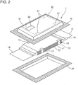
- Fig. 2 is the exploded perspective view
- Fig. 3 is the enlarged cross-sectional view taken along the line III-III in Fig. 1 .
- the film covered battery 1 is formed into a flat rectangular shape.
- the film covered battery has a battery element 10, and two films 41 and 42 for hermetically sealing the battery element 10.
- battery element 10 has a plurality of rectangular electrode plates, comprised of positive electrode plates 11 and negative electrode plates 12, laminated alternately via separators 18 (see Fig. 3 ).
- the size (i.e., the area) of the positive electrode plate 11 is dimensioned to be less than that of the negative electrode plate 12.
- Binding members (tapes 13) are attached to two opposed long-side walls of the battery element 10 for binding the positive electrode plates 11 and the negative electrode plates 12 together. More concretely, tapes 13 are attached to two points of each of the long-side walls respectively. Each tape 13 is attached to extend over the electrode plate at the uppermost layer (i.e., the negative electrode plate 12a shown in Fig.
- each tape 13 is attached to the surface of the negative electrode plate 12a at the uppermost layer, whereas the other end of each tape 13 is attached to the surface of the negative electrode plate 12b at the lowermost layer.
- the thickness of tape 13 is approximately 50 ⁇ m.
- a positive-electrode extension 14 is drawn out from each of the positive electrode plates 11, whereas a negative-electrode extension 15 is drawn out from each of the negative electrode plates 12. Furthermore, each of the positive-electrode extensions 14 is collectively joined to one end of a positive electrode lead 16, whereas each of the negative-electrode extensions 15 is collectively joined to one end of a negative electrode lead 17.
- a positive-electrode active material is applied to both faces of the positive electrode plate 11, whereas a negative-electrode active material is applied to both faces of the negative electrode plate 12.
- An insulating layer 19 is placed between the positive electrode plate 11 and the separator 18. Concretely, to provide the insulating layer 19, an insulating film is laid out between the positive electrode plate 11 and each of the separators 18 located on both sides of the same positive electrode plate, in a manner so as to straddle the border between the positive-electrode active material coated area and the positive-electrode extension 14.
- one end of the insulating layer 19 is laid out to cover an end of the positive-electrode active material applied to the positive electrode plate 11, whereas the other end is laid out to cover the root of the positive-electrode extension 14 extending outside of the separator 18.
- the thickness of the insulating layer 19 is approximately 30 ⁇ m.
- Each of films 41 and 42 is a laminate film having the laminated structure shown in Fig. 4 . That is to say, each of films 41 and 42 has at least a heat-fusion bonding layer (or a heat-sealing layer) 43, a metal layer 44, and a protective layer 45.
- Heat-fusion bonding layer 43 is formed of polypropylene (PP)
- metal layer 44 is formed of aluminum (Al)
- protective layer 45 is formed of polyethylene terephthalate (PET).
- the thickness of each of films 41-42 is approximately 120 ⁇ m, whereas the thickness of protective layer 45 is approximately 20 ⁇ m. By the way, the thickness of each of films 41-42 and/or the thickness of each of the layers may be appropriately changed. Additionally, the material of each of the layers is not limited to the particular embodiments shown and described herein.
- films 41-42 are laid out, such that their heat-fusion bonding layers 43 (see Fig. 4 ) are arranged to be inwardly opposed to each other and that the battery element 10 is sandwiched between them in the vertical direction. Additionally, the two opposed heat-fusion bonding layers 43 of films 41-42 are heat-bonded each other. In Fig. 2 , the heat-bonded area of the heat-fusion bonding layer 43 of each of films 41-42 is indicated as the diagonal shading area.
- These two films 41-42, integrally connected to each other by heat-fusion bonding, are hereinafter referred to as "exterior film 40".
- the one end of the positive electrode lead 16 is drawn out from one side (a short side) of the exterior film 40 to extend outside of the exterior film 40.
- the one end of the negative electrode lead 17 is drawn out from the other side (the other short side) of the exterior film 40 to extend outside thereof.
- a cover film which is a feature of the invention, is hereinafter explained.
- the cover film 50 having a thickness of approximately 50 ⁇ m is partially attached to the surface of the exterior film 40.
- Fig. 5 shows the cross section taken along the line V-V of Fig. 1 .
- cover film 50 is attached to a very small hollow 51 occurred on the surface of the protective layer 45 (see Fig. 4 ) of the exterior film 40.
- the reason for the occurrence of the very small hollow 51 on the surface of the exterior film 40 is as having mentioned previously.
- cover film 50 is attached only within predetermined regions set on the surface of the film covered battery.
- a first region 60 is set on the surface of film 41, whereas a second region 62 is set on the surface of film 42.
- the first region 60 and the second region 62 are substantially the same.
- the first region 60 set on the surface of film 41 is explained in detail.
- the second region 62 set on the surface of film 42 only the difference of the second region from the first region 60 will be explained.
- the first region 60 is indicated by the broken line.
- the first region 60 set on the surface of film 41 is substantially the same as a projected region obtained by projecting the electrode plate (i.e., the positive electrode plate 11 in Fig. 3 ) to the surface of film 41 (i.e., the surface of the protective layer 45).
- the negative electrode plate 12a at the uppermost layer may be used as a projected object, but it is preferable to use, as a projected object for the projected region, the positive electrode plate 11 having a size (an area) less than the negative electrode plate 12a located at the uppermost layer.
- the ends 13a of tapes 13 exist within the previously-discussed projected region. Additionally, as shown in Fig. 3 , a part of each of the insulating layers 19 exists within the projected region. Therefore, as shown in Figs. 3 and 5 , the level difference, corresponding to the thickness of tape 13 or the thickness of the insulating layer 19, exists within the projected region. In other words, a region (an overlap region 61) of the projected region, overlapping with the ends 13a of tapes 13 or a part of each of the insulating layers 19, is higher than the other region. Therefore, when the cover film 50 is attached onto the overlap region 61, the thickness of the film covered battery 1 tends to increase by the thickness of the cover tape 50. In contrast, when the cover tape 50 is attached onto the other region except the overlap region 61, the thickness of the cover film 50 can be absorbed by the level difference between the overlap region 61 and the other region.
- the thickness of the cover film 50 is approximately 50 ⁇ m, whereas the thickness of the insulating layer 19 is approximately 30 ⁇ m.
- the insulating layers 19 are attached to both sides (the upside and the underside, that is, two layers) of each of the positive electrode plate 11.
- the thickness of 90 ⁇ m can be assured toward the upside of the battery, while the thickness of 90 ⁇ m can be assured toward the underside of the battery, and hence the thickness of the cover film 50 of 50 ⁇ m can be absorbed. Therefore, the level difference, greater than the thickness of the cover film 50, exists between the overlap region of the projected region overlapping with the insulating layers 19 and the other region.
- the thickness of tape 13 and the thickness of cover film 50 are 50 ⁇ m, and hence the level difference for absorbing the thickness of cover film 50 exists between the overlap region of the projected region overlapping with the tapes 13a and the other region.
- the first region 60 set on the surface of film 41 is a region obtained by removing the first overlap region 61 from the projected region obtained by projecting the positive electrode plate 11 to the surface of film 41.
- the second region 62 set on the surface of film 42 is a region obtained by removing the second overlap region 61 from the projected region obtained by projecting the positive electrode plate 11 to the surface of film 42.
- the predetermined regions are the remaining regions obtained by removing the overlap regions, overlapping with members (tapes 13a) interposed between the electrode plates at the outermost layers and the exterior film and members (insulating layers 19) interposed between the electrode plates and the separators, from the projected region obtained by projecting the electrode plates to the surface of the exterior film.
- some kind of members, except the ends of tapes 13 may be interposed between the electrode plates at the outermost layers and the film 41. In such a case, an overlap region of the projected region, overlapping with this kind of members, is also included in the overlap region 61.
- At least one of the electrode plate at the uppermost layer and the electrode plate at the lowermost layer in the battery element 10 may be a positive electrode plate. Even when the positive electrode plate is placed at the uppermost layer, it is preferable to use the positive electrode plate having a smaller area as a projected electrode plate, constructing the projected region.
- first region 60 and the second region 62 may be enlarged by eliminating either one of tapes 13 and insulating layers 19.
- cover film 50 shown herein is rectangular, but the shape of cover film 50 is not limited to such a rectangular shape. Additionally, it is preferable that the shortest distance between the border of the very small hollow 51 and the border of the cover film 50 is 5 mm or more.
- the cover film 50 of the shown embodiment has a two-layer structure comprised of an adhesive layer and a resin layer. A released paper is attached to the adhesive layer. When attaching the cover film 50 to the surface of the exterior film 40, the released paper is peeled off, and thus the adhesive layer is exposed.
- the structure of cover film 50 is not limited to the above-mentioned structure.
- two or more cover films 50 may be attached to the surface of the exterior film 40 without overlapping each other.
- a plurality of cover films, differing from each other in size and/or thickness, may be used in combination.
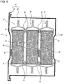
- a battery module 2 using the film covered battery of the invention there is shown one example of a battery module 2 using the film covered battery of the invention.
- three film covered batteries 1A, 1B, and 1C are housed in a module case 3, and unified together.
- Module case 3 is constructed by a box-type casing main body 3a and a cover 3b. These three film covered batteries 1A-1C are housed in the casing main body 3a, while being stacked up in their thickness directions.
- the cover films 50 are attached to the first region 60 of the film covered battery 1A of the upper section and the first region 60 of the film covered battery 1C of the lower section, respectively. Additionally, the cover film 50 is attached to the second region 62 of the film covered battery 1B of the middle section.
- the thickness of the cover film 50 can be absorbed by the level difference between the first region 60 and the overlap region 61.
- the thickness of the cover film 50 can be absorbed by the level difference between the second region 62 and the overlap region 61. That is, in any one of the film covered batteries, there is no increase in thickness due to the attached cover film 50.
- the thickness (the height) of the battery module 2 is identical to that of a battery module using film covered batteries to which cover films are not attached. In this manner, even in a battery module that film covered batteries are housed and stacked up in their thickness directions, any increase in thickness does not occur.
- a module assembly 4 using the battery module shown in Fig. 6 there is shown one example of a module assembly 4 using the battery module shown in Fig. 6 .
- a plurality of battery modules 2 are installed in a housing 5 by a two-step stack.
- each battery module 2 of the upper section is mounted on each battery module 2 of the lower section.
- a retainer plate 6, which extends over the battery modules adjacent to each other, is mounted on the cover 3b (see Fig. 6 ) of battery module 2 of the upper section.
- Bolts 7, each of which passes through the retainer plate 6, are installed to also pass through both of the battery module 2 of the upper section and the battery module 2 of the lower section.
- the battery module 2 of the upper section and the battery module 2 of the lower section are fastened and unified together with bolts 7, passing through them, while the battery modules, adjacent to each other, are unified together by means of the retainer plate 6.
- the plurality of battery modules 2 are integrally connected to each other.
- housing 5 is not mandatory, but it may be eliminated.
- the module assembly 4 shown in Fig. 7 is utilized for various purposes.
- the module assembly is often utilized for an electric vehicle battery.
- the module assembly 4 is laid out under a seat 9 of an electric vehicle 8.
- the plurality of module assemblies 4 may be laid out in a stacked state in a space defined under the seat 9. That is, housing 5 may be eliminated.
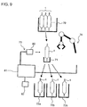
- Fig. 9 is the schematic view illustrating a part of the manufacturing line of the film covered battery 1.
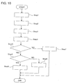
- Fig. 10 is the flowchart illustrating the flow of the screening process.
- the determination means 73 is comprised of a camera 80, a computer 81 for image-processing picture images photographed by the camera 80 and for determining the presence or absence of a very small hollow, and a memory 82 for storing programs executed by the computer 81 and various data.
- the locomotion means 74 is comprised of a robot arm configured to operate based on a command from the computer 81.
- the flow of the screening process is hereinafter explained in reference to Fig. 10 .
- the common tray 70 in which a plurality of film covered batteries 1 are stored, is conveyed to a predetermined position by means of a conveyance means (not shown).
- the robot arm 74 picks up any one of the film covered batteries 1 from the common tray 70 (see Step 1), and then moves the picked-up film covered battery 1 to the inspection stage 71 (see Step 2).
- a picture image of the film covered battery 1 on the inspection stage 71 is taken by the camera 80 (see Step 3).
- the photography image, taken by the camera 80, is inputted into the computer 81, and then the inputted photography image is image-processed by the computer 81 (see Step 4).
- the computer 81 discriminates or determines, based on the result of the image-processing, the presence or absence of a very small hollow (see Step 5).
- the computer 81 detects, based on brightness information within the photography image, the border (the edge) of the film covered battery 1 and a very small hollow. More concretely, within the photography image, the brightness tends to rapidly change in front and in rear of picture elements, corresponding to the border of the film covered battery 1.
- the border of the film covered battery 1 can be detected by obtaining the picture element, whose brightness rapidly changes as compared to the picture elements adjacent to each other, and its coordinates. Furthermore, when a very small hollow is present on the surface of the film covered battery 1, the brightness tends to rapidly change in front and in rear of the picture element, corresponding to the very small hollow. Thus, the presence or absence of a very small hollow can be detected by determining whether the picture element, whose brightness rapidly changes as compared to the picture elements adjacent to each other, is present or absent inside of the detected border of the film covered battery 1.
- the computer 81 determines whether or not the very small hollow is present in either one of the previously-discussed first region 60 and the previously-discussed second region 62 (see Step 6). Concretely, the computer 81 is configured to obtain the coordinates of the picture element, corresponding to the very small hollow, (i.e., the picture element whose brightness rapidly changes as compared to the picture elements adjacent to each other). On the other hand, region information, indicating the coordinates of the boundary of the first region 60 or the coordinates of the boundary of the second region 62, is pre-stored in the memory 82. The computer 81 compares the region information read from the memory 82 with the coordinates of the picture element corresponding to the very small hollow, and then determines whether the very small hollow is present inside of the first region 60 or the second region 62.
- region information indicating the coordinates of the boundary of the first region 60 or the coordinates of the boundary of the second region 62
- Step 5 determines that a very small hollow is absent
- the film covered battery 1 is moved to the first distribution tray 72a by the robot arm 74 (see Step 7).
- Step 6 determines that a very small hollow is present outside of the predetermined regions
- the film covered battery 1 is moved to the second distribution tray 72b by the robot arm 74 (see Step 8).
- Step 6 determines that a very small hollow is present in the predetermined regions
- the film covered battery 1 is moved to the third distribution tray 72c by the robot arm 74 (see Step 9).
- Step 6 determines that a very small hollow is present in the predetermined regions and thus the previously-discussed cover film 50 is attached to the very small hollow
- a process for determining whether the cover film 50 protrudes from the predetermined regions may be carried out as an additional process.
- size information indicating the size of cover film 50
- the computer 81 performs the above-mentioned determination based on the size information and the region information, both read from the memory 82, and the coordinates indicating the center of the very small hollow. At this time, the above-mentioned determination is made on the assumption that the cover film 50 is attached such that the center of the cover film 50 and the center of the very small hollow coincide with each other.
- a symbol or a character, indicating the result of determination through Step 5 and the result of determination through Step 6, may be printed on the surface of the film covered battery 1.
- an ink jet printer may be utilized.
- a symbol, indicating the result of determination has been printed, it is unnecessary to distribute, based on the result of determination, the film covered battery 1 into an appropriate one of the different distribution trays 72a-72c.
- cover film may be attached to the very small hollow by means of a manipulator or the like, while using the detected coordinate data.
Landscapes
- Chemical & Material Sciences (AREA)
- General Chemical & Material Sciences (AREA)
- Chemical Kinetics & Catalysis (AREA)
- Electrochemistry (AREA)
- Engineering & Computer Science (AREA)
- Transportation (AREA)
- Mechanical Engineering (AREA)
- Manufacturing & Machinery (AREA)
- Combustion & Propulsion (AREA)
- Life Sciences & Earth Sciences (AREA)
- Sustainable Development (AREA)
- Sustainable Energy (AREA)
- Power Engineering (AREA)
- Sealing Battery Cases Or Jackets (AREA)
- Secondary Cells (AREA)
- Battery Mounting, Suspending (AREA)
Claims (10)
- Beschichtete Batterie (1), umfassend:ein Batterieelement (10), das mit einer Vielzahl von Elektrodenplatten (11, 12) versehen ist, die mittels Separatoren (18) laminiert sind; undeine Außenschicht (40) zum hermetischen Abdichten des Batterieelements (10), dadurch gekennzeichnet, dasseine Deckschicht (50) an einem Hohlraum (51) angebracht ist, der in einer Außenfläche der Außenschicht (40) angeordnet ist und teilweise an einem Teil der Außenfläche der Außenschicht (40) zum Abdecken des Hohlraums (51) angebracht ist, wobei die Deckschicht (50) in vorgegebenen Bereichen (60, 62) vorhanden ist, die auf der Außenfläche der Außenschicht (40) angeordnet sind, und dassdie vorgegebenen Bereiche (60, 62) Bereiche sind, die durch Entfernen von Überlappungsbereichen (61) von projizierten Bereichen erhalten wurden, die durch Projizieren der Elektrodenplatten auf die Außenfläche der Außenschicht (40) erhalten wurden, wobei die Überlappungsbereiche (61)(a) Bereiche sind, an denen vorragende Bereiche ein Bindeglied (13), das zwischen einer obersten Elektrodenplatte (12a) und der Außenschicht (40) und einer untersten Elektrodenplatte (12b) und der Außenschicht (40) angeordnet ist, wobei ein erstes Ende des Bindeglieds (13) an der obersten Elektrodenplatte (12a) befestigt ist, und ein zweites Ende des Bindeglieds (13) an der untersten Elektrodenplatte (12b) befestigt ist, zum Verbinden der Vielzahl von Elektrodenplatten (11, 12) überlappen, die mittels den Separatoren (18) laminiert sind,(b) Bereiche sind, an denen die vorragenden Bereiche eine Vielzahl von Isolierschichten (19) überlappen, die zwischen zugeordneten Elektrodenplatten (11, 12) und einem an die zugeordneten Elektrodenplatten (11, 12) angrenzenden Separator (18) angeordnet sind, oder(c) Bereiche sind, die sowohl durch das Bindeglied (13), dessen Enden jeweils an der obersten Elektrodenplatte (12a) und der untersten Elektrodenplatte (12b) befestigt sind, wobei ein erstes Ende des Bindeglieds (13) an der obersten Elektrodenplatte (12a) befestigt ist, und ein zweites Ende des Bindeglieds (13) an der untersten Elektrodenplatte (12b) befestigt ist, und die Vielzahl von Isolierschichten (19) bestimmt sind, die zwischen den zugeordneten Elektrodenplatten (11, 12) und dem an die zugeordneten Elektrodenplatten (11, 12) angrenzenden Separator (18) platziert sind, und dass(i) ein Höhenunterschied zwischen den Überlappungsbereichen (61) und den vorgegebenen Bereichen (60, 62) vorhanden ist;(ii) der Höhenunterschied größer als die Dicke der Deckschicht (50) ist; und(iii) die Deckschicht (50) nicht in den Überlappungsbereichen (61) vorhanden ist.
- Beschichtete Batterie (1) nach Anspruch 1, dadurch gekennzeichnet, dass
die vorgegebenen Bereiche einen ersten Bereich (60), der auf der Außenseite der Außenschicht (40) an einer ersten Seite der beschichteten Batterie festgelegt ist, und einen zweiten Bereich (62) umfasst, der auf der Außenseite der Außenschicht (40) an einer zweiten Seite der beschichteten Batterie festgelegt ist, wobei die zweite Seite der ersten Seite gegenüberliegt;
der erste Bereich (60) ein Bereich ist, der durch Entfernen eines ersten Überlappungsbereichs (61) von einem vorragenden Bereich erhalten wurde, der durch Projizieren der obersten Elektrodenplatte (12a) auf die Außenfläche der Außenschicht (40) auf der ersten Seite der beschichteten Batterie erhalten wurde, wobei der erste Überlappungsbereich (61) das erste Ende (13a) des Bindeglieds (13) überlappt, das an der obersten Elektrodenplatte (12a) befestigt ist;
der zweite Bereich (62) ein Bereich ist, der durch Entfernen eines zweiten Überlappungsbereichs (61) von einem projizierten Bereich erhalten wird, der durch Projizieren der untersten Elektrodenplatte (12b) auf die Außenfläche der Außenschicht (40) auf der zweiten Seite der beschichteten Batterie erhalten wird, wobei der zweite Überlappungsbereich (61) das zweite Ende (13a) des Bindeglieds (13) überlappt, das an der untersten Elektrodenplatte (12b) befestigt ist; und
die Abdeckschicht (50) am ersten Bereich (60) und/oder zweiten Bereich (62) angebracht ist. - Beschichtete Batterie (1) nach Anspruch 1, dadurch gekennzeichnet, dass
ein Bindeglied (13) nicht vorgesehen ist; und
die Überlappungsbereiche (61) Bereiche sind, an denen die vorragenden Bereiche die Isolierschicht (19) überlappen. - Beschichtete Batterie (1) nach einem der vorhergehenden Ansprüche 1 bis 3, dadurch gekennzeichnet, dass
die Elektrodenplatten große Elektrodenplatten (12) mit einer ersten Fläche und kleine Elektrodenplatten (11) mit einer zweiten Fläche aufweisen, wobei die zweite Fläche kleiner als die erste Fläche ist;
die Elektrodenplatten, welche die vorragenden Bereiche bilden, die kleinen Elektrodenplatten (11) sind; und
die Isolierschicht (19) zwischen einer zugeordneten kleinen Elektrodenplatte (11) und einem an die zugeordneten kleine Elektrodenplatte (11) angrenzenden Separator (18) angeordnet ist. - Batteriemodul (2), umfassend:eine Vielzahl von beschichteten Batterien (1A, 1B, 1C), die in gestapeltem Zustand untergebracht sind, wobei jede der beschichteten Batterien die beschichtete Batterie nach einem der vorhergehenden Ansprüche 1 bis 4 aufweist, dadurch gekennzeichnet, dassdie Vielzahl der beschichteten Batterien (1A, 1B, 1C) entlang einer Laminierungsrichtung der Elektrodenplatten (11, 12) gestapelt sind, die das Batterieelement (10) bilden.
- Modul-Baugruppe (4), umfassend:eine Vielzahl von Batteriemodulen (2), wobei jedes der Batteriemodule das Batteriemodul nach Anspruch 5 aufweist, dadurch gekennzeichnet, dassdie Vielzahl der Batteriemodule (2) in gestapeltem Zustand angeordnet sind und miteinander verbunden sind.
- Elektrofahrzeug, umfassend:
die Modul-Baugruppe (4) nach Anspruch 6, dadurch gekennzeichnet, dass die Modul-Baugruppe (4) unter einem Fahrzeugsitz platziert ist. - Verfahren zum Herstellen einer beschichteten Batterie (1) nach Anspruch 1, wobei das Verfahren umfasst:Fertigstellen einer beschichteten Batterie (1) durch hermetisches Abdichten eines Batterieelements (10), das mit einer Vielzahl von Elektrodenplatten (11, 12) versehen ist, die mittels Separatoren (18) laminiert sind, durch eine Außenschicht (40); undÜberprüfen, ob die beschichtete Batterie (1) eine beschichtete Batterie mit einem Hohlraum (51), der in einer Außenfläche der Außenschicht (40) in vorgegebenen Bereichen (60, 62) angeordnet ist, die auf der Außenfläche der Außenschicht (40) festgelegt sind, oder eine beschichtete Batterie ohne den in der Außenfläche der Außenschicht (40) in den vorgegebenen Bereichen (60, 62) angeordneten Hohlraum (51) ist, gekennzeichnet durchAnbringen einer Deckschicht (50) im Hohlraum (51) und einem Teil der Außenfläche der Außenschicht (40) zum Abdecken des Hohlraums (51), und durchden Schritt des Überprüfens, umfassend:das Unterscheiden des vorhandenen oder nicht vorhandenen Hohlraums (51) auf der Oberfläche der beschichteten Batterie (1); unddas Ermitteln, ob eine Position des Hohlraums (51) innerhalb der vorgegebenen Bereiche (60, 62) liegt, und durchdie vorgegebenen Bereiche (61, 62), die Bereiche sind, die durch Entfernen von Überlappungsbereichen (61) von den vorragenden Bereichen erhalten werden, die durch Projizieren der Elektrodenplatten auf die Außenfläche der Außenschicht (40) erhalten werden, wobei die Überlappungsbereiche (61)(a) Bereiche sind, an denen vorragende Bereiche ein Bindeglied (13), das zwischen einer obersten Elektrodenplatte (12a) und der Außenschicht (40) und einer untersten Elektrodenplatte (12b) und der Außenschicht (40) angeordnet ist, wobei ein erstes Ende des Bindeglieds (13) an der obersten Elektrodenplatte (12a) befestigt ist; und ein zweites Ende des Bindeglieds (13) an der untersten Elektrodenplatte (12b) befestigt ist, zum Verbinden der Vielzahl von Elektrodenplatten (11, 12) überlappen, die mittels den Separatoren (18) laminiert sind,(b) Bereiche sind, an denen die vorragenden Bereiche eine Vielzahl von Isolierschichten (19) überlappen, die zwischen zugeordneten Elektrodenplatten (11, 12) und einem an die zugeordneten Elektrodenplatten (11, 12) angrenzenden Separator (18) angeordnet sind, oder(c) Bereiche sind, die sowohl durch das Bindeglied (13), dessen Enden jeweils an der obersten Elektrodenplatte (12a) und der untersten Elektrodenplatte (12b) befestigt sind, wobei ein erstes Ende des Bindeglieds (13) an der obersten Elektrodenplatte (12a) befestigt ist; und ein zweites Ende des Bindeglieds (13) an der untersten Elektrodenplatte (12b) befestigt ist, und der Vielzahl von Isolierschichten (19) bestimmt sind, die zwischen den zugeordneten Elektrodenplatten (11, 12) und dem an die zugeordneten Elektrodenplatten (11, 12) angrenzenden Separator (18) platziert sind.
- Verfahren zum Herstellen einer beschichteten Batterie (1) nach Anspruch 8, dadurch gekennzeichnet, dass
das Bindeglied (13) nicht vorgesehen ist; und
die Überlappungsbereiche (61 Bereiche sind, an denen die vorragenden Bereiche die Isolierschicht (19) überlappen. - Verfahren zum Herstellen einer beschichteten Batterie (1) nach Anspruch 8, das ferner umfasst:
das Ermitteln, ob die Deckschicht (50), die eine vorgegebene Größe zum Abdecken des Hohlraums (51) aufweist, aus den vorgegebenen Bereichen (60, 62) vorragt.
Applications Claiming Priority (2)
| Application Number | Priority Date | Filing Date | Title |
|---|---|---|---|
| JP2010293001A JP5757730B2 (ja) | 2010-12-28 | 2010-12-28 | フィルム外装電池、電池モジュール、モジュール集合体、フィルム外装電池の製造方法、および電気自動車 |
| PCT/JP2011/078099 WO2012090652A1 (ja) | 2010-12-28 | 2011-12-05 | フィルム外装電池およびその選別方法 |
Publications (3)
| Publication Number | Publication Date |
|---|---|
| EP2660892A1 EP2660892A1 (de) | 2013-11-06 |
| EP2660892A4 EP2660892A4 (de) | 2016-09-07 |
| EP2660892B1 true EP2660892B1 (de) | 2018-08-22 |
Family
ID=46382771
Family Applications (1)
| Application Number | Title | Priority Date | Filing Date |
|---|---|---|---|
| EP11852423.0A Active EP2660892B1 (de) | 2010-12-28 | 2011-12-05 | Filmbeschichtete batterie und entsprechendes screening-verfahren |
Country Status (8)
| Country | Link |
|---|---|
| US (1) | US9837643B2 (de) |
| EP (1) | EP2660892B1 (de) |
| JP (1) | JP5757730B2 (de) |
| KR (1) | KR101719030B1 (de) |
| CN (1) | CN103314465B (de) |
| BR (1) | BR112013013889A2 (de) |
| MX (1) | MX2013005979A (de) |
| WO (1) | WO2012090652A1 (de) |
Families Citing this family (23)
| Publication number | Priority date | Publication date | Assignee | Title |
|---|---|---|---|---|
| JP5757730B2 (ja) | 2010-12-28 | 2015-07-29 | オートモーティブエナジーサプライ株式会社 | フィルム外装電池、電池モジュール、モジュール集合体、フィルム外装電池の製造方法、および電気自動車 |
| WO2014141753A1 (ja) * | 2013-03-12 | 2014-09-18 | Necエナジーデバイス株式会社 | 電池モジュール |
| JP2014238958A (ja) | 2013-06-07 | 2014-12-18 | オートモーティブエナジーサプライ株式会社 | 非水系電池 |
| JPWO2015002094A1 (ja) * | 2013-07-05 | 2017-02-23 | Necエナジーデバイス株式会社 | 電池セル |
| JP5804117B2 (ja) | 2014-03-26 | 2015-11-04 | 株式会社豊田自動織機 | 蓄電装置 |
| WO2015173686A1 (en) | 2014-05-16 | 2015-11-19 | Semiconductor Energy Laboratory Co., Ltd. | Electronic device with secondary battery |
| KR102465163B1 (ko) | 2016-06-22 | 2022-11-08 | 가부시키가이샤 한도오따이 에네루기 켄큐쇼 | 전지, 및 전지의 제작 방법 |
| JP6932128B2 (ja) * | 2016-07-22 | 2021-09-08 | 株式会社エンビジョンAescジャパン | 電気化学デバイス |
| WO2018033880A2 (en) | 2016-08-17 | 2018-02-22 | Shape Corp. | Battery support and protection structure for a vehicle |
| EP3566253B1 (de) | 2017-01-04 | 2022-12-28 | Shape Corp. | Batterieträgerstruktur für ein fahrzeug |
| JP2018127250A (ja) * | 2017-02-09 | 2018-08-16 | 日産自動車株式会社 | シート貼付装置 |
| US10483510B2 (en) | 2017-05-16 | 2019-11-19 | Shape Corp. | Polarized battery tray for a vehicle |
| US11211656B2 (en) | 2017-05-16 | 2021-12-28 | Shape Corp. | Vehicle battery tray with integrated battery retention and support feature |
| WO2018213306A1 (en) | 2017-05-16 | 2018-11-22 | Shape Corp. | Vehicle battery tray having tub-based component |
| CN109216776B (zh) * | 2017-06-30 | 2022-10-25 | 远景Aesc日本有限公司 | 电化学器件 |
| WO2019055658A2 (en) | 2017-09-13 | 2019-03-21 | Shape Corp. | VEHICLE BATTERY TRAY WITH TUBULAR PERIPHERAL WALL |
| US12347879B2 (en) | 2017-09-13 | 2025-07-01 | Shape Corp. | Vehicle battery tray with tubular peripheral wall |
| CN111201155A (zh) | 2017-10-04 | 2020-05-26 | 形状集团 | 用于电动车辆的电池托盘底板组件 |
| WO2019169080A1 (en) | 2018-03-01 | 2019-09-06 | Shape Corp. | Cooling system integrated with vehicle battery tray |
| US11688910B2 (en) | 2018-03-15 | 2023-06-27 | Shape Corp. | Vehicle battery tray having tub-based component |
| CN110690408B (zh) * | 2018-07-05 | 2021-08-06 | 宁德新能源科技有限公司 | 电芯及其电池 |
| JP7246889B2 (ja) * | 2018-10-19 | 2023-03-28 | 株式会社エンビジョンAescジャパン | 組電池およびその製造方法 |
| KR102316340B1 (ko) | 2019-01-22 | 2021-10-22 | 주식회사 엘지에너지솔루션 | 전극조립체, 그를 포함하는 이차전지, 이차전지 제조방법 및 전지팩 |
Family Cites Families (16)
| Publication number | Priority date | Publication date | Assignee | Title |
|---|---|---|---|---|
| US6673488B2 (en) * | 2001-07-23 | 2004-01-06 | Ngk Spark Plug Co., Ltd. | Packaging for polymer electrolytic cell and method of forming same |
| JP2003092132A (ja) * | 2001-09-14 | 2003-03-28 | Mitsubishi Electric Corp | 電 池 |
| US20030232236A1 (en) * | 2002-06-14 | 2003-12-18 | Mitchell Porter H. | Battery package vent |
| KR100472504B1 (ko) * | 2002-06-17 | 2005-03-10 | 삼성에스디아이 주식회사 | 보강구조가 개선된 파우치형 이차전지 |
| JP4424053B2 (ja) | 2004-04-28 | 2010-03-03 | トヨタ自動車株式会社 | ラミネート型二次電池、およびその組電池 |
| BRPI0514352A (pt) | 2004-10-18 | 2008-06-10 | Lg Chemical Ltd | bateria secundária empregando invólucro de bateria de alta resistência |
| KR20060105208A (ko) | 2005-04-01 | 2006-10-11 | 주식회사 엘지화학 | 매우 얇은 두께의 전지팩 |
| JP2006294351A (ja) * | 2005-04-07 | 2006-10-26 | Nec Lamilion Energy Ltd | フィルム外装電気デバイスの製造方法 |
| KR100947982B1 (ko) * | 2006-03-28 | 2010-03-18 | 삼성에스디아이 주식회사 | 전극 조립체 및 이를 가지는 파우치형 리튬 이차 전지 |
| JP5481766B2 (ja) * | 2006-03-29 | 2014-04-23 | 日本電気株式会社 | フィルム外装電池の製造方法 |
| KR101151110B1 (ko) * | 2007-02-21 | 2012-06-01 | 닛본 덴끼 가부시끼가이샤 | 전지 실장체, 적층 전지 어셈블리 및 필름 외장 전지 |
| JP5023391B2 (ja) * | 2007-08-06 | 2012-09-12 | Necエナジーデバイス株式会社 | ラミネート電池の製造方法 |
| JP5031606B2 (ja) * | 2008-01-30 | 2012-09-19 | ソニー株式会社 | 電池パック及びその製造方法 |
| WO2009113470A1 (ja) * | 2008-03-14 | 2009-09-17 | 日本電気株式会社 | 被覆材及びフィルム外装電気デバイス |
| CN201681980U (zh) | 2010-05-14 | 2010-12-22 | 能元科技股份有限公司 | 可撕式电池套膜以及具有该可撕式电池套膜的电池 |
| JP5757730B2 (ja) | 2010-12-28 | 2015-07-29 | オートモーティブエナジーサプライ株式会社 | フィルム外装電池、電池モジュール、モジュール集合体、フィルム外装電池の製造方法、および電気自動車 |
-
2010
- 2010-12-28 JP JP2010293001A patent/JP5757730B2/ja active Active
-
2011
- 2011-12-05 US US13/976,587 patent/US9837643B2/en active Active
- 2011-12-05 WO PCT/JP2011/078099 patent/WO2012090652A1/ja not_active Ceased
- 2011-12-05 BR BR112013013889A patent/BR112013013889A2/pt not_active Application Discontinuation
- 2011-12-05 MX MX2013005979A patent/MX2013005979A/es active IP Right Grant
- 2011-12-05 CN CN201180063116.4A patent/CN103314465B/zh active Active
- 2011-12-05 KR KR1020137013448A patent/KR101719030B1/ko active Active
- 2011-12-05 EP EP11852423.0A patent/EP2660892B1/de active Active
Non-Patent Citations (1)
| Title |
|---|
| None * |
Also Published As
| Publication number | Publication date |
|---|---|
| BR112013013889A2 (pt) | 2016-10-04 |
| CN103314465B (zh) | 2015-11-25 |
| JP5757730B2 (ja) | 2015-07-29 |
| CN103314465A (zh) | 2013-09-18 |
| JP2012142144A (ja) | 2012-07-26 |
| KR101719030B1 (ko) | 2017-03-22 |
| EP2660892A1 (de) | 2013-11-06 |
| EP2660892A4 (de) | 2016-09-07 |
| WO2012090652A1 (ja) | 2012-07-05 |
| KR20140003428A (ko) | 2014-01-09 |
| US9837643B2 (en) | 2017-12-05 |
| US20130284531A1 (en) | 2013-10-31 |
| RU2013135414A (ru) | 2015-02-10 |
| MX2013005979A (es) | 2013-07-15 |
Similar Documents
| Publication | Publication Date | Title |
|---|---|---|
| EP2660892B1 (de) | Filmbeschichtete batterie und entsprechendes screening-verfahren | |
| US20120219847A1 (en) | Pouch type battery and its manufacturing method | |
| JP6589663B2 (ja) | 検査方法、積層型電池の製造方法、検査装置、および積層型電池の製造装置 | |
| KR101624386B1 (ko) | 테이프를 이용한 전극조립체의 고정방법 | |
| EP2020695A2 (de) | Beutelartiges Batteriepack | |
| JP2012142144A5 (ja) | フィルム外装電池、電池モジュール、モジュール集合体、フィルム外装電池の製造方法、および電気自動車 | |
| JP7031300B2 (ja) | 蓄電素子及び蓄電装置 | |
| KR20160019314A (ko) | 커브드 이차 전지 및 이의 제조 방법 | |
| KR102222111B1 (ko) | 이차 전지 | |
| KR101219252B1 (ko) | 이차 전지용 파우치 케이스 및 이를 이용한 이차 전지 | |
| US20240347756A1 (en) | Electrode assembly and secondary battery including the same | |
| JP6930673B2 (ja) | 蓄電デバイス、電動自動車及び蓄電デバイスの製造方法 | |
| US20160268557A1 (en) | Rechargeable battery | |
| US20170349297A1 (en) | Structural composite component and method for configuring a structural composite component | |
| JP5484297B2 (ja) | 二次電池 | |
| JP5332256B2 (ja) | 薄型電池 | |
| KR101923303B1 (ko) | 축전 셀, 외장 필름 및 축전 모듈 | |
| CN111837284B (zh) | 电极组件、包含其的二次电池、用于制造二次电池的方法及电池组 | |
| KR102591518B1 (ko) | 배터리 팩 및 라벨 시트 | |
| RU2575482C2 (ru) | Заключенный в пленочную оболочку аккумулятор и способ его проверки | |
| JP6911668B2 (ja) | 蓄電モジュールの製造方法及び製造装置 | |
| US20150026969A1 (en) | Battery reinforcement method | |
| KR102656480B1 (ko) | 배터리 팩 | |
| JP2007122968A (ja) | 電気デバイス集合体 | |
| JP7574827B2 (ja) | 電極体の製造方法、電極体の製造装置、および、電極体 |
Legal Events
| Date | Code | Title | Description |
|---|---|---|---|
| PUAI | Public reference made under article 153(3) epc to a published international application that has entered the european phase |
Free format text: ORIGINAL CODE: 0009012 |
|
| 17P | Request for examination filed |
Effective date: 20130605 |
|
| AK | Designated contracting states |
Kind code of ref document: A1 Designated state(s): AL AT BE BG CH CY CZ DE DK EE ES FI FR GB GR HR HU IE IS IT LI LT LU LV MC MK MT NL NO PL PT RO RS SE SI SK SM TR |
|
| DAX | Request for extension of the european patent (deleted) | ||
| RA4 | Supplementary search report drawn up and despatched (corrected) |
Effective date: 20160809 |
|
| RIC1 | Information provided on ipc code assigned before grant |
Ipc: H01M 2/04 20060101ALI20160803BHEP Ipc: H01M 2/30 20060101AFI20160803BHEP Ipc: H01M 2/26 20060101ALI20160803BHEP Ipc: H01M 2/02 20060101ALI20160803BHEP Ipc: H01M 2/06 20060101ALI20160803BHEP Ipc: H01M 2/08 20060101ALN20160803BHEP Ipc: H01M 10/04 20060101ALI20160803BHEP Ipc: H01M 2/10 20060101ALI20160803BHEP |
|
| 17Q | First examination report despatched |
Effective date: 20170329 |
|
| REG | Reference to a national code |
Ref country code: DE Ref legal event code: R079 Ref document number: 602011051415 Country of ref document: DE Free format text: PREVIOUS MAIN CLASS: H01M0002020000 Ipc: H01M0002300000 |
|
| GRAP | Despatch of communication of intention to grant a patent |
Free format text: ORIGINAL CODE: EPIDOSNIGR1 |
|
| INTG | Intention to grant announced |
Effective date: 20180321 |
|
| RIC1 | Information provided on ipc code assigned before grant |
Ipc: H01M 2/26 20060101ALI20180309BHEP Ipc: H01M 2/10 20060101ALI20180309BHEP Ipc: H01M 2/04 20060101ALI20180309BHEP Ipc: H01M 2/30 20060101AFI20180309BHEP Ipc: H01M 2/02 20060101ALI20180309BHEP Ipc: H01M 2/06 20060101ALI20180309BHEP Ipc: H01M 10/04 20060101ALI20180309BHEP Ipc: H01M 2/08 20060101ALN20180309BHEP |
|
| GRAS | Grant fee paid |
Free format text: ORIGINAL CODE: EPIDOSNIGR3 |
|
| GRAA | (expected) grant |
Free format text: ORIGINAL CODE: 0009210 |
|
| RAP1 | Party data changed (applicant data changed or rights of an application transferred) |
Owner name: AUTOMOTIVE ENERGY SUPPLY CORPORATION Owner name: NISSAN MOTOR CO., LTD. |
|
| AK | Designated contracting states |
Kind code of ref document: B1 Designated state(s): AL AT BE BG CH CY CZ DE DK EE ES FI FR GB GR HR HU IE IS IT LI LT LU LV MC MK MT NL NO PL PT RO RS SE SI SK SM TR |
|
| REG | Reference to a national code |
Ref country code: GB Ref legal event code: FG4D |
|
| REG | Reference to a national code |
Ref country code: CH Ref legal event code: EP |
|
| REG | Reference to a national code |
Ref country code: AT Ref legal event code: REF Ref document number: 1033492 Country of ref document: AT Kind code of ref document: T Effective date: 20180915 |
|
| REG | Reference to a national code |
Ref country code: IE Ref legal event code: FG4D |
|
| REG | Reference to a national code |
Ref country code: DE Ref legal event code: R096 Ref document number: 602011051415 Country of ref document: DE |
|
| REG | Reference to a national code |
Ref country code: NL Ref legal event code: MP Effective date: 20180822 |
|
| REG | Reference to a national code |
Ref country code: LT Ref legal event code: MG4D |
|
| PG25 | Lapsed in a contracting state [announced via postgrant information from national office to epo] |
Ref country code: IS Free format text: LAPSE BECAUSE OF FAILURE TO SUBMIT A TRANSLATION OF THE DESCRIPTION OR TO PAY THE FEE WITHIN THE PRESCRIBED TIME-LIMIT Effective date: 20181222 Ref country code: NL Free format text: LAPSE BECAUSE OF FAILURE TO SUBMIT A TRANSLATION OF THE DESCRIPTION OR TO PAY THE FEE WITHIN THE PRESCRIBED TIME-LIMIT Effective date: 20180822 Ref country code: RS Free format text: LAPSE BECAUSE OF FAILURE TO SUBMIT A TRANSLATION OF THE DESCRIPTION OR TO PAY THE FEE WITHIN THE PRESCRIBED TIME-LIMIT Effective date: 20180822 Ref country code: LT Free format text: LAPSE BECAUSE OF FAILURE TO SUBMIT A TRANSLATION OF THE DESCRIPTION OR TO PAY THE FEE WITHIN THE PRESCRIBED TIME-LIMIT Effective date: 20180822 Ref country code: FI Free format text: LAPSE BECAUSE OF FAILURE TO SUBMIT A TRANSLATION OF THE DESCRIPTION OR TO PAY THE FEE WITHIN THE PRESCRIBED TIME-LIMIT Effective date: 20180822 Ref country code: SE Free format text: LAPSE BECAUSE OF FAILURE TO SUBMIT A TRANSLATION OF THE DESCRIPTION OR TO PAY THE FEE WITHIN THE PRESCRIBED TIME-LIMIT Effective date: 20180822 Ref country code: GR Free format text: LAPSE BECAUSE OF FAILURE TO SUBMIT A TRANSLATION OF THE DESCRIPTION OR TO PAY THE FEE WITHIN THE PRESCRIBED TIME-LIMIT Effective date: 20181123 Ref country code: BG Free format text: LAPSE BECAUSE OF FAILURE TO SUBMIT A TRANSLATION OF THE DESCRIPTION OR TO PAY THE FEE WITHIN THE PRESCRIBED TIME-LIMIT Effective date: 20181122 Ref country code: NO Free format text: LAPSE BECAUSE OF FAILURE TO SUBMIT A TRANSLATION OF THE DESCRIPTION OR TO PAY THE FEE WITHIN THE PRESCRIBED TIME-LIMIT Effective date: 20181122 |
|
| REG | Reference to a national code |
Ref country code: AT Ref legal event code: MK05 Ref document number: 1033492 Country of ref document: AT Kind code of ref document: T Effective date: 20180822 |
|
| PG25 | Lapsed in a contracting state [announced via postgrant information from national office to epo] |
Ref country code: HR Free format text: LAPSE BECAUSE OF FAILURE TO SUBMIT A TRANSLATION OF THE DESCRIPTION OR TO PAY THE FEE WITHIN THE PRESCRIBED TIME-LIMIT Effective date: 20180822 Ref country code: LV Free format text: LAPSE BECAUSE OF FAILURE TO SUBMIT A TRANSLATION OF THE DESCRIPTION OR TO PAY THE FEE WITHIN THE PRESCRIBED TIME-LIMIT Effective date: 20180822 Ref country code: AL Free format text: LAPSE BECAUSE OF FAILURE TO SUBMIT A TRANSLATION OF THE DESCRIPTION OR TO PAY THE FEE WITHIN THE PRESCRIBED TIME-LIMIT Effective date: 20180822 |
|
| PG25 | Lapsed in a contracting state [announced via postgrant information from national office to epo] |
Ref country code: RO Free format text: LAPSE BECAUSE OF FAILURE TO SUBMIT A TRANSLATION OF THE DESCRIPTION OR TO PAY THE FEE WITHIN THE PRESCRIBED TIME-LIMIT Effective date: 20180822 Ref country code: IT Free format text: LAPSE BECAUSE OF FAILURE TO SUBMIT A TRANSLATION OF THE DESCRIPTION OR TO PAY THE FEE WITHIN THE PRESCRIBED TIME-LIMIT Effective date: 20180822 Ref country code: CZ Free format text: LAPSE BECAUSE OF FAILURE TO SUBMIT A TRANSLATION OF THE DESCRIPTION OR TO PAY THE FEE WITHIN THE PRESCRIBED TIME-LIMIT Effective date: 20180822 Ref country code: EE Free format text: LAPSE BECAUSE OF FAILURE TO SUBMIT A TRANSLATION OF THE DESCRIPTION OR TO PAY THE FEE WITHIN THE PRESCRIBED TIME-LIMIT Effective date: 20180822 Ref country code: AT Free format text: LAPSE BECAUSE OF FAILURE TO SUBMIT A TRANSLATION OF THE DESCRIPTION OR TO PAY THE FEE WITHIN THE PRESCRIBED TIME-LIMIT Effective date: 20180822 Ref country code: ES Free format text: LAPSE BECAUSE OF FAILURE TO SUBMIT A TRANSLATION OF THE DESCRIPTION OR TO PAY THE FEE WITHIN THE PRESCRIBED TIME-LIMIT Effective date: 20180822 Ref country code: PL Free format text: LAPSE BECAUSE OF FAILURE TO SUBMIT A TRANSLATION OF THE DESCRIPTION OR TO PAY THE FEE WITHIN THE PRESCRIBED TIME-LIMIT Effective date: 20180822 |
|
| REG | Reference to a national code |
Ref country code: DE Ref legal event code: R097 Ref document number: 602011051415 Country of ref document: DE |
|
| PG25 | Lapsed in a contracting state [announced via postgrant information from national office to epo] |
Ref country code: SK Free format text: LAPSE BECAUSE OF FAILURE TO SUBMIT A TRANSLATION OF THE DESCRIPTION OR TO PAY THE FEE WITHIN THE PRESCRIBED TIME-LIMIT Effective date: 20180822 Ref country code: SM Free format text: LAPSE BECAUSE OF FAILURE TO SUBMIT A TRANSLATION OF THE DESCRIPTION OR TO PAY THE FEE WITHIN THE PRESCRIBED TIME-LIMIT Effective date: 20180822 Ref country code: DK Free format text: LAPSE BECAUSE OF FAILURE TO SUBMIT A TRANSLATION OF THE DESCRIPTION OR TO PAY THE FEE WITHIN THE PRESCRIBED TIME-LIMIT Effective date: 20180822 |
|
| PLBE | No opposition filed within time limit |
Free format text: ORIGINAL CODE: 0009261 |
|
| STAA | Information on the status of an ep patent application or granted ep patent |
Free format text: STATUS: NO OPPOSITION FILED WITHIN TIME LIMIT |
|
| 26N | No opposition filed |
Effective date: 20190523 |
|
| REG | Reference to a national code |
Ref country code: CH Ref legal event code: PL |
|
| PG25 | Lapsed in a contracting state [announced via postgrant information from national office to epo] |
Ref country code: LU Free format text: LAPSE BECAUSE OF NON-PAYMENT OF DUE FEES Effective date: 20181205 Ref country code: SI Free format text: LAPSE BECAUSE OF FAILURE TO SUBMIT A TRANSLATION OF THE DESCRIPTION OR TO PAY THE FEE WITHIN THE PRESCRIBED TIME-LIMIT Effective date: 20180822 Ref country code: MC Free format text: LAPSE BECAUSE OF FAILURE TO SUBMIT A TRANSLATION OF THE DESCRIPTION OR TO PAY THE FEE WITHIN THE PRESCRIBED TIME-LIMIT Effective date: 20180822 |
|
| REG | Reference to a national code |
Ref country code: IE Ref legal event code: MM4A |
|
| REG | Reference to a national code |
Ref country code: BE Ref legal event code: MM Effective date: 20181231 Ref country code: DE Ref legal event code: R082 Ref document number: 602011051415 Country of ref document: DE Representative=s name: HOEFER & PARTNER PATENTANWAELTE MBB, DE Ref country code: DE Ref legal event code: R081 Ref document number: 602011051415 Country of ref document: DE Owner name: ENVISION AESC JAPAN LTD., ZAMA-SHI, JP Free format text: FORMER OWNERS: AUTOMOTIVE ENERGY SUPPLY CORP., ZAMA-SHI, KANAGAWA, JP; NISSAN MOTOR CO., LTD., YOKOHAMA-SHI, JP |
|
| REG | Reference to a national code |
Ref country code: GB Ref legal event code: 732E Free format text: REGISTERED BETWEEN 20190926 AND 20191002 |
|
| PG25 | Lapsed in a contracting state [announced via postgrant information from national office to epo] |
Ref country code: IE Free format text: LAPSE BECAUSE OF NON-PAYMENT OF DUE FEES Effective date: 20181205 |
|
| PG25 | Lapsed in a contracting state [announced via postgrant information from national office to epo] |
Ref country code: BE Free format text: LAPSE BECAUSE OF NON-PAYMENT OF DUE FEES Effective date: 20181231 |
|
| PG25 | Lapsed in a contracting state [announced via postgrant information from national office to epo] |
Ref country code: LI Free format text: LAPSE BECAUSE OF NON-PAYMENT OF DUE FEES Effective date: 20181231 Ref country code: CH Free format text: LAPSE BECAUSE OF NON-PAYMENT OF DUE FEES Effective date: 20181231 |
|
| PG25 | Lapsed in a contracting state [announced via postgrant information from national office to epo] |
Ref country code: MT Free format text: LAPSE BECAUSE OF NON-PAYMENT OF DUE FEES Effective date: 20181205 |
|
| PG25 | Lapsed in a contracting state [announced via postgrant information from national office to epo] |
Ref country code: TR Free format text: LAPSE BECAUSE OF FAILURE TO SUBMIT A TRANSLATION OF THE DESCRIPTION OR TO PAY THE FEE WITHIN THE PRESCRIBED TIME-LIMIT Effective date: 20180822 |
|
| PG25 | Lapsed in a contracting state [announced via postgrant information from national office to epo] |
Ref country code: PT Free format text: LAPSE BECAUSE OF FAILURE TO SUBMIT A TRANSLATION OF THE DESCRIPTION OR TO PAY THE FEE WITHIN THE PRESCRIBED TIME-LIMIT Effective date: 20180822 |
|
| PG25 | Lapsed in a contracting state [announced via postgrant information from national office to epo] |
Ref country code: MK Free format text: LAPSE BECAUSE OF NON-PAYMENT OF DUE FEES Effective date: 20180822 Ref country code: CY Free format text: LAPSE BECAUSE OF FAILURE TO SUBMIT A TRANSLATION OF THE DESCRIPTION OR TO PAY THE FEE WITHIN THE PRESCRIBED TIME-LIMIT Effective date: 20180822 Ref country code: HU Free format text: LAPSE BECAUSE OF FAILURE TO SUBMIT A TRANSLATION OF THE DESCRIPTION OR TO PAY THE FEE WITHIN THE PRESCRIBED TIME-LIMIT; INVALID AB INITIO Effective date: 20111205 |
|
| REG | Reference to a national code |
Ref country code: DE Ref legal event code: R079 Ref document number: 602011051415 Country of ref document: DE Free format text: PREVIOUS MAIN CLASS: H01M0002300000 Ipc: H01M0050543000 |
|
| P01 | Opt-out of the competence of the unified patent court (upc) registered |
Effective date: 20230330 |
|
| PGFP | Annual fee paid to national office [announced via postgrant information from national office to epo] |
Ref country code: DE Payment date: 20251022 Year of fee payment: 15 |
|
| PGFP | Annual fee paid to national office [announced via postgrant information from national office to epo] |
Ref country code: GB Payment date: 20251023 Year of fee payment: 15 |
|
| PGFP | Annual fee paid to national office [announced via postgrant information from national office to epo] |
Ref country code: FR Payment date: 20251023 Year of fee payment: 15 |