US9837643B2 - Film covered battery and method for screening same - Google Patents
Film covered battery and method for screening same Download PDFInfo
- Publication number
- US9837643B2 US9837643B2 US13/976,587 US201113976587A US9837643B2 US 9837643 B2 US9837643 B2 US 9837643B2 US 201113976587 A US201113976587 A US 201113976587A US 9837643 B2 US9837643 B2 US 9837643B2
- Authority
- US
- United States
- Prior art keywords
- film
- battery
- regions
- region
- electrode plate
- Prior art date
- Legal status (The legal status is an assumption and is not a legal conclusion. Google has not performed a legal analysis and makes no representation as to the accuracy of the status listed.)
- Active, expires
Links
Images


Classifications
-
- B—PERFORMING OPERATIONS; TRANSPORTING
- B60—VEHICLES IN GENERAL
- B60K—ARRANGEMENT OR MOUNTING OF PROPULSION UNITS OR OF TRANSMISSIONS IN VEHICLES; ARRANGEMENT OR MOUNTING OF PLURAL DIVERSE PRIME-MOVERS IN VEHICLES; AUXILIARY DRIVES FOR VEHICLES; INSTRUMENTATION OR DASHBOARDS FOR VEHICLES; ARRANGEMENTS IN CONNECTION WITH COOLING, AIR INTAKE, GAS EXHAUST OR FUEL SUPPLY OF PROPULSION UNITS IN VEHICLES
- B60K1/00—Arrangement or mounting of electrical propulsion units
- B60K1/04—Arrangement or mounting of electrical propulsion units of the electric storage means for propulsion
-
- H01M2/0237—
-
- B—PERFORMING OPERATIONS; TRANSPORTING
- B60—VEHICLES IN GENERAL
- B60L—PROPULSION OF ELECTRICALLY-PROPELLED VEHICLES; SUPPLYING ELECTRIC POWER FOR AUXILIARY EQUIPMENT OF ELECTRICALLY-PROPELLED VEHICLES; ELECTRODYNAMIC BRAKE SYSTEMS FOR VEHICLES IN GENERAL; MAGNETIC SUSPENSION OR LEVITATION FOR VEHICLES; MONITORING OPERATING VARIABLES OF ELECTRICALLY-PROPELLED VEHICLES; ELECTRIC SAFETY DEVICES FOR ELECTRICALLY-PROPELLED VEHICLES
- B60L50/00—Electric propulsion with power supplied within the vehicle
- B60L50/50—Electric propulsion with power supplied within the vehicle using propulsion power supplied by batteries or fuel cells
- B60L50/60—Electric propulsion with power supplied within the vehicle using propulsion power supplied by batteries or fuel cells using power supplied by batteries
- B60L50/66—Arrangements of batteries
-
- H—ELECTRICITY
- H01—ELECTRIC ELEMENTS
- H01M—PROCESSES OR MEANS, e.g. BATTERIES, FOR THE DIRECT CONVERSION OF CHEMICAL ENERGY INTO ELECTRICAL ENERGY
- H01M10/00—Secondary cells; Manufacture thereof
- H01M10/04—Construction or manufacture in general
- H01M10/0413—Large-sized flat cells or batteries for motive or stationary systems with plate-like electrodes
-
- H01M2/0262—
-
- H01M2/0267—
-
- H01M2/0469—
-
- H01M2/06—
-
- H01M2/1072—
-
- H01M2/1077—
-
- H01M2/1083—
-
- H01M2/266—
-
- H01M2/305—
-
- H—ELECTRICITY
- H01—ELECTRIC ELEMENTS
- H01M—PROCESSES OR MEANS, e.g. BATTERIES, FOR THE DIRECT CONVERSION OF CHEMICAL ENERGY INTO ELECTRICAL ENERGY
- H01M50/00—Constructional details or processes of manufacture of the non-active parts of electrochemical cells other than fuel cells, e.g. hybrid cells
- H01M50/10—Primary casings; Jackets or wrappings
- H01M50/102—Primary casings; Jackets or wrappings characterised by their shape or physical structure
- H01M50/105—Pouches or flexible bags
-
- H—ELECTRICITY
- H01—ELECTRIC ELEMENTS
- H01M—PROCESSES OR MEANS, e.g. BATTERIES, FOR THE DIRECT CONVERSION OF CHEMICAL ENERGY INTO ELECTRICAL ENERGY
- H01M50/00—Constructional details or processes of manufacture of the non-active parts of electrochemical cells other than fuel cells, e.g. hybrid cells
- H01M50/10—Primary casings; Jackets or wrappings
- H01M50/116—Primary casings; Jackets or wrappings characterised by the material
- H01M50/124—Primary casings; Jackets or wrappings characterised by the material having a layered structure
-
- H—ELECTRICITY
- H01—ELECTRIC ELEMENTS
- H01M—PROCESSES OR MEANS, e.g. BATTERIES, FOR THE DIRECT CONVERSION OF CHEMICAL ENERGY INTO ELECTRICAL ENERGY
- H01M50/00—Constructional details or processes of manufacture of the non-active parts of electrochemical cells other than fuel cells, e.g. hybrid cells
- H01M50/20—Mountings; Secondary casings or frames; Racks, modules or packs; Suspension devices; Shock absorbers; Transport or carrying devices; Holders
- H01M50/204—Racks, modules or packs for multiple batteries or multiple cells
- H01M50/207—Racks, modules or packs for multiple batteries or multiple cells characterised by their shape
- H01M50/211—Racks, modules or packs for multiple batteries or multiple cells characterised by their shape adapted for pouch cells
-
- H—ELECTRICITY
- H01—ELECTRIC ELEMENTS
- H01M—PROCESSES OR MEANS, e.g. BATTERIES, FOR THE DIRECT CONVERSION OF CHEMICAL ENERGY INTO ELECTRICAL ENERGY
- H01M50/00—Constructional details or processes of manufacture of the non-active parts of electrochemical cells other than fuel cells, e.g. hybrid cells
- H01M50/50—Current conducting connections for cells or batteries
- H01M50/531—Electrode connections inside a battery casing
- H01M50/54—Connection of several leads or tabs of plate-like electrode stacks, e.g. electrode pole straps or bridges
-
- B—PERFORMING OPERATIONS; TRANSPORTING
- B60—VEHICLES IN GENERAL
- B60Y—INDEXING SCHEME RELATING TO ASPECTS CROSS-CUTTING VEHICLE TECHNOLOGY
- B60Y2200/00—Type of vehicle
- B60Y2200/90—Vehicles comprising electric prime movers
- B60Y2200/91—Electric vehicles
-
- H01M2/08—
-
- H—ELECTRICITY
- H01—ELECTRIC ELEMENTS
- H01M—PROCESSES OR MEANS, e.g. BATTERIES, FOR THE DIRECT CONVERSION OF CHEMICAL ENERGY INTO ELECTRICAL ENERGY
- H01M2220/00—Batteries for particular applications
- H01M2220/20—Batteries in motive systems, e.g. vehicle, ship, plane
-
- H—ELECTRICITY
- H01—ELECTRIC ELEMENTS
- H01M—PROCESSES OR MEANS, e.g. BATTERIES, FOR THE DIRECT CONVERSION OF CHEMICAL ENERGY INTO ELECTRICAL ENERGY
- H01M50/00—Constructional details or processes of manufacture of the non-active parts of electrochemical cells other than fuel cells, e.g. hybrid cells
- H01M50/10—Primary casings; Jackets or wrappings
- H01M50/172—Arrangements of electric connectors penetrating the casing
- H01M50/174—Arrangements of electric connectors penetrating the casing adapted for the shape of the cells
- H01M50/178—Arrangements of electric connectors penetrating the casing adapted for the shape of the cells for pouch or flexible bag cells
-
- H—ELECTRICITY
- H01—ELECTRIC ELEMENTS
- H01M—PROCESSES OR MEANS, e.g. BATTERIES, FOR THE DIRECT CONVERSION OF CHEMICAL ENERGY INTO ELECTRICAL ENERGY
- H01M50/00—Constructional details or processes of manufacture of the non-active parts of electrochemical cells other than fuel cells, e.g. hybrid cells
- H01M50/50—Current conducting connections for cells or batteries
- H01M50/543—Terminals
- H01M50/547—Terminals characterised by the disposition of the terminals on the cells
- H01M50/548—Terminals characterised by the disposition of the terminals on the cells on opposite sides of the cell
-
- H—ELECTRICITY
- H01—ELECTRIC ELEMENTS
- H01M—PROCESSES OR MEANS, e.g. BATTERIES, FOR THE DIRECT CONVERSION OF CHEMICAL ENERGY INTO ELECTRICAL ENERGY
- H01M50/00—Constructional details or processes of manufacture of the non-active parts of electrochemical cells other than fuel cells, e.g. hybrid cells
- H01M50/50—Current conducting connections for cells or batteries
- H01M50/543—Terminals
- H01M50/552—Terminals characterised by their shape
- H01M50/553—Terminals adapted for prismatic, pouch or rectangular cells
-
- Y—GENERAL TAGGING OF NEW TECHNOLOGICAL DEVELOPMENTS; GENERAL TAGGING OF CROSS-SECTIONAL TECHNOLOGIES SPANNING OVER SEVERAL SECTIONS OF THE IPC; TECHNICAL SUBJECTS COVERED BY FORMER USPC CROSS-REFERENCE ART COLLECTIONS [XRACs] AND DIGESTS
- Y02—TECHNOLOGIES OR APPLICATIONS FOR MITIGATION OR ADAPTATION AGAINST CLIMATE CHANGE
- Y02E—REDUCTION OF GREENHOUSE GAS [GHG] EMISSIONS, RELATED TO ENERGY GENERATION, TRANSMISSION OR DISTRIBUTION
- Y02E60/00—Enabling technologies; Technologies with a potential or indirect contribution to GHG emissions mitigation
- Y02E60/10—Energy storage using batteries
-
- Y—GENERAL TAGGING OF NEW TECHNOLOGICAL DEVELOPMENTS; GENERAL TAGGING OF CROSS-SECTIONAL TECHNOLOGIES SPANNING OVER SEVERAL SECTIONS OF THE IPC; TECHNICAL SUBJECTS COVERED BY FORMER USPC CROSS-REFERENCE ART COLLECTIONS [XRACs] AND DIGESTS
- Y02—TECHNOLOGIES OR APPLICATIONS FOR MITIGATION OR ADAPTATION AGAINST CLIMATE CHANGE
- Y02P—CLIMATE CHANGE MITIGATION TECHNOLOGIES IN THE PRODUCTION OR PROCESSING OF GOODS
- Y02P70/00—Climate change mitigation technologies in the production process for final industrial or consumer products
- Y02P70/50—Manufacturing or production processes characterised by the final manufactured product
-
- Y—GENERAL TAGGING OF NEW TECHNOLOGICAL DEVELOPMENTS; GENERAL TAGGING OF CROSS-SECTIONAL TECHNOLOGIES SPANNING OVER SEVERAL SECTIONS OF THE IPC; TECHNICAL SUBJECTS COVERED BY FORMER USPC CROSS-REFERENCE ART COLLECTIONS [XRACs] AND DIGESTS
- Y02—TECHNOLOGIES OR APPLICATIONS FOR MITIGATION OR ADAPTATION AGAINST CLIMATE CHANGE
- Y02T—CLIMATE CHANGE MITIGATION TECHNOLOGIES RELATED TO TRANSPORTATION
- Y02T10/00—Road transport of goods or passengers
- Y02T10/60—Other road transportation technologies with climate change mitigation effect
- Y02T10/70—Energy storage systems for electromobility, e.g. batteries
-
- Y—GENERAL TAGGING OF NEW TECHNOLOGICAL DEVELOPMENTS; GENERAL TAGGING OF CROSS-SECTIONAL TECHNOLOGIES SPANNING OVER SEVERAL SECTIONS OF THE IPC; TECHNICAL SUBJECTS COVERED BY FORMER USPC CROSS-REFERENCE ART COLLECTIONS [XRACs] AND DIGESTS
- Y10—TECHNICAL SUBJECTS COVERED BY FORMER USPC
- Y10T—TECHNICAL SUBJECTS COVERED BY FORMER US CLASSIFICATION
- Y10T29/00—Metal working
- Y10T29/49—Method of mechanical manufacture
- Y10T29/49002—Electrical device making
- Y10T29/49108—Electric battery cell making
- Y10T29/4911—Electric battery cell making including sealing
Definitions
- the present invention relates to a film covered battery.
- a generally-known film covered battery has a battery element and an exterior film for hermetically sealing the battery element.
- the exterior film has at least a heat-fusion bonding layer, a metal layer, and a protective layer.
- a very small hollow may occur on the surface of the film covered battery due to an external force. For instance, when the film covered battery is picked up by means of a robot hand, a very small hollow may occur on the surface of the protective layer of the exterior film.
- Patent document 1 teaches a method of manufacturing a laminated battery using a laminated film with a protective film attached to a protective layer.
- the protective film whose adhesive strength decreases by ultraviolet irradiation, is attached to the surface of the laminated film in advance, and a film covered battery is manufactured, using a battery element as well as the laminated film, and thereafter only the protective film is removed by ultraviolet irradiation.
- the previously-discussed method requires a process for exfoliating the protective film. Assuming that a hollow has already occurred on the protective layer before attaching the protective film, such a hollow is exposed by exfoliating the protective film. In contrast, assuming that, for the purpose of covering the hollow, the protective film is left on the surface of the laminated film, in the Patent document 1 the thickness of the film covered battery increases because of the protective film attached over the entire surface of the protective layer of the laminated film.
- a film covered battery is used in a state where a large number of film covered batteries are stacked up in their thickness directions.
- the total thickness of the stacked or assembled film covered batteries greatly increases.
- Patent document 1 Japanese patent provisional publication No. 2009-043442 (A)
- a film covered battery of the invention has a battery element equipped with a plurality of electrode plates laminated via separators, an exterior film for hermetically sealing the battery element, and a cover film attached to a hollow present in predetermined regions set on a surface of the exterior film.
- the predetermined regions are regions obtained by removing overlap regions from projected regions obtained by projecting the electrode plates to the surface of the exterior film, the overlap regions being regions where the projected regions overlap with members interposed between the electrode plates at the outermost layers and the exterior film or between the electrode plates and the separators.
- the aforementioned members include a binding member, whose ends are fixed to respective surfaces of the electrode plates at the outermost layers.
- the predetermined regions include a first region set on one surface of the exterior film and a second region set on the other surface of the exterior film.
- the first region is a region obtained by removing a first overlap region from a projected region obtained by projecting the electrode plate at the uppermost layer to the one surface of the exterior film, the first overlap region overlapping with one end of each of binding members fixed to the one surface of the electrode plate at the uppermost layer.
- the second region is a region obtained by removing a second overlap region from a projected region obtained by projecting the electrode plate at the lowermost layer to the other surface of the exterior film, the second overlap region overlapping with the other end of each of the binding members fixed to the other surface of the electrode plate at the lowermost layer.
- the cover film is attached to at least one of the first region and the second region.
- the previously-discussed members include insulating films placed between the electrode plates and the separators.
- each of the previously-discussed members include a binding member, whose ends are fixed to respective surfaces of the electrode plates at the outermost layers, and insulating films placed between the electrode plates and the separators.
- electrode plates each of which has a relatively large area
- electrode plates each of which has a relatively small area
- the electrode plates, constructing the above-mentioned projected regions are the electrode plates, each having the relatively small area.
- a battery module of the invention has a plurality of film covered batteries of the invention and a case in which the plurality of film covered batteries are housed in a stacked state.
- the plurality of film covered batteries are stacked along a direction of laminating of the electrode plates constructing the battery element.
- a plurality of battery modules of the invention are laid out in a stacked state, and the plurality of battery modules are connected to each other.
- the above-mentioned module assembly of the invention is placed under a vehicle seat.
- the invention includes a method for screening a film covered battery, whose battery element is equipped with a plurality of electrode plates laminated via separators and hermetically sealed by an exterior film, before attaching a cover film to a hollow on a surface.
- the method has a step (a process) for discriminating the presence or absence of the hollow on the surface of the film covered battery, and a step (a process) for determining whether a position of the hollow is within predetermined regions.
- the above-mentioned predetermined regions are regions obtained by removing overlap regions from projected regions obtained by projecting the electrode plates to a surface of the exterior film, the overlap regions being regions where the projected regions overlap with members interposed between the electrode plates at the outermost layers and the exterior film or between the electrode plates and the separators.
- the method further includes a step for determining whether the cover film, having a predetermined size for covering the hollow, protrudes from the predetermined regions.
- FIG. 1 is a perspective view illustrating the appearance of an embodiment of a film covered battery.
- FIG. 2 is an exploded perspective view illustrating the film covered battery shown in FIG. 1 .
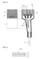
- FIG. 3 is an enlarged cross-sectional view taken along the line in FIG. 1 .
- FIG. 4 is a schematic cross-sectional view illustrating the laminated structure of the film.
- FIG. 5 is a cross-sectional view taken along the line V-V in FIG. 1 .
- FIG. 6 is a cross-sectional view illustrating an embodiment of a battery module.
- FIG. 7 is a partial cross-sectional view illustrating an embodiment of a module assembly.
- FIG. 8 is a schematic view illustrating an example of the use of the module assembly.
- FIG. 9 is a schematic view illustrating a part of a manufacturing line of the film covered battery.
- FIG. 10 is a chart illustrating a screening process of the film covered battery.
- FIG. 1 is the perspective view illustrating the appearance of a film covered battery 1 of the embodiment
- FIG. 2 is the exploded perspective view
- FIG. 3 is the enlarged cross-sectional view taken along the line III-III in FIG. 1 .
- the film covered battery 1 is formed into a flat rectangular shape.
- the film covered battery has a battery element 10 , and two films 41 and 42 for hermetically sealing the battery element 10 .
- battery element 10 has a plurality of rectangular electrode plates, comprised of positive electrode plates 11 and negative electrode plates 12 , laminated alternately via separators 18 (see FIG. 3 ).
- the size (i.e., the area) of the positive electrode plate 11 is dimensioned to be less than that of the negative electrode plate 12 .
- Binding members (tapes 13 ) are attached to two opposed long-side walls of the battery element 10 for binding the positive electrode plates 11 and the negative electrode plates 12 together. More concretely, tapes 13 are attached to two points of each of the long-side walls respectively. Each tape 13 is attached to extend over the electrode plate at the uppermost layer (i.e., the negative electrode plate 12 a shown in FIG.
- each tape 13 is attached to the surface of the negative electrode plate 12 a at the uppermost layer, whereas the other end of each tape 13 is attached to the surface of the negative electrode plate 12 b at the lowermost layer.
- the thickness of tape 13 is approximately 50 ⁇ m.
- a positive-electrode extension 14 is drawn out from each of the positive electrode plates 11 , whereas a negative-electrode extension 15 is drawn out from each of the negative electrode plates 12 . Furthermore, each of the positive-electrode extensions 14 is collectively joined to one end of a positive electrode lead 16 , whereas each of the negative-electrode extensions 15 is collectively joined to one end of a negative electrode lead 17 .
- a positive-electrode active material is applied to both faces of the positive electrode plate 11
- a negative-electrode active material is applied to both faces of the negative electrode plate 12
- An insulating layer 19 is placed between the positive electrode plate 11 and the separator 18 .
- an insulating film is laid out between the positive electrode plate 11 and each of the separators 18 located on both sides of the same positive electrode plate, in a manner so as to straddle the border between the positive-electrode active material coated area and the positive-electrode extension 14 .
- one end of the insulating layer 19 is laid out to cover an end of the positive-electrode active material applied to the positive electrode plate 11 , whereas the other end is laid out to cover the root of the positive-electrode extension 14 extending outside of the separator 18 .
- the thickness of the insulating layer 19 is approximately 30 ⁇ m.
- Each of films 41 and 42 is a laminate film having the laminated structure shown in FIG. 4 . That is to say, each of films 41 and 42 has at least a heat-fusion bonding layer (or a heat-sealing layer) 43 , a metal layer 44 , and a protective layer 45 .
- Heat-fusion bonding layer 43 is formed of polypropylene (PP)
- metal layer 44 is formed of aluminum (Al)
- protective layer 45 is formed of polyethylene terephthalate (PET).
- the thickness of each of films 41 - 42 is approximately 120 ⁇ m, whereas the thickness of protective layer 45 is approximately 20 ⁇ m. By the way, the thickness of each of films 41 - 42 and/or the thickness of each of the layers may be appropriately changed. Additionally, the material of each of the layers is not limited to the particular embodiments shown and described herein.
- films 41 - 42 are laid out, such that their heat-fusion bonding layers 43 (see FIG. 4 ) are arranged to be inwardly opposed to each other and that the battery element 10 is sandwiched between them in the vertical direction. Additionally, the two opposed heat-fusion bonding layers 43 of films 41 - 42 are heat-bonded each other. In FIG. 2 , the heat-bonded area of the heat-fusion bonding layer 43 of each of films 41 - 42 is indicated as the diagonal shading area.
- These two films 41 - 42 integrally connected to each other by heat-fusion bonding, are hereinafter referred to as “exterior film 40 ”.
- the one end of the positive electrode lead 16 is drawn out from one side (a short side) of the exterior film 40 to extend outside of the exterior film 40 .
- the one end of the negative electrode lead 17 is drawn out from the other side (the other short side) of the exterior film 40 to extend outside thereof.
- FIGS. 1-2 A cover film, which is a feature of the invention, is hereinafter explained.
- the cover film 50 having a thickness of approximately 50 ⁇ m is partially attached to the surface of the exterior film 40 .
- FIG. 5 shows the cross section taken along the line V-V of FIG. 1 .
- cover film 50 is attached to a very small hollow 51 occurred on the surface of the protective layer 45 (see FIG. 4 ) of the exterior film 40 .
- the reason for the occurrence of the very small hollow 51 on the surface of the exterior film 40 is as having mentioned previously.
- cover film 50 is attached only within predetermined regions set on the surface of the film covered battery.
- a first region 60 is set on the surface of film 41
- a second region 62 is set on the surface of film 42 .
- the first region 60 and the second region 62 are substantially the same.
- the first region 60 set on the surface of film 41 is explained in detail.
- the second region 62 set on the surface of film 42 only the difference of the second region from the first region 60 will be explained.
- the first region 60 is indicated by the broken line.
- the first region 60 set on the surface of film 41 is substantially the same as a projected region obtained by projecting the electrode plate (i.e., the positive electrode plate 11 in FIG. 3 ) to the surface of film 41 (i.e., the surface of the protective layer 45 ).
- the negative electrode plate 12 a at the uppermost layer may be used as a projected object, but it is preferable to use, as a projected object for the projected region, the positive electrode plate 11 having a size (an area) less than the negative electrode plate 12 a located at the uppermost layer.
- the ends 13 a of tapes 13 exist within the previously-discussed projected region. Additionally, as shown in FIG. 3 , a part of each of the insulating layers 19 exists within the projected region. Therefore, as shown in FIGS. 3 and 5 , the level difference, corresponding to the thickness of tape 13 or the thickness of the insulating layer 19 , exists within the projected region. In other words, a region (an overlap region 61 ) of the projected region, overlapping with the ends 13 a of tapes 13 or a part of each of the insulating layers 19 , is higher than the other region. Therefore, when the cover film 50 is attached onto the overlap region 61 , the thickness of the film covered battery 1 tends to increase by the thickness of the cover film 50 . In contrast, when the cover film 50 is attached onto the other region except the overlap region 61 , the thickness of the cover film 50 can be absorbed by the level difference between the overlap region 61 and the other region.
- the thickness of the cover film 50 is approximately 50 ⁇ m, whereas the thickness of the insulating layer 19 is approximately 30 ⁇ m.
- the insulating layers 19 are attached to both sides (the upside and the underside, that is, two layers) of each of the positive electrode plate 11 .
- the thickness of 90 ⁇ m can be assured toward the upside of the battery, while the thickness of 90 ⁇ m can be assured toward the underside of the battery, and hence the thickness of the cover film 50 of 50 ⁇ m can be absorbed. Therefore, the level difference, greater than the thickness of the cover film 50 , exists between the overlap region of the projected region overlapping with the insulating layers 19 and the other region.
- the thickness of tape 13 and the thickness of cover film 50 are 50 ⁇ m, and hence the level difference for absorbing the thickness of cover film 50 exists between the overlap region of the projected region overlapping with the tapes 13 a and the other region.
- the first region 60 set on the surface of film 41 is a region obtained by removing the first overlap region 61 from the projected region obtained by projecting the positive electrode plate 11 to the surface of film 41 .
- the second region 62 set on the surface of film 42 is a region obtained by removing the second overlap region 61 from the projected region obtained by projecting the positive electrode plate 11 to the surface of film 42 .
- the predetermined regions are the remaining regions obtained by removing the overlap regions, overlapping with members (tapes 13 a ) interposed between the electrode plates at the outermost layers and the exterior film and members (insulating layers 19 ) interposed between the electrode plates and the separators, from the projected region obtained by projecting the electrode plates to the surface of the exterior film.
- some kind of members except the ends of tapes 13 , may be interposed between the electrode plates at the outermost layers and the film 41 .
- an overlap region of the projected region, overlapping with this kind of members is also included in the overlap region 61 .
- At least one of the electrode plate at the uppermost layer and the electrode plate at the lowermost layer in the battery element 10 may be a positive electrode plate. Even when the positive electrode plate is placed at the uppermost layer, it is preferable to use the positive electrode plate having a smaller area as a projected electrode plate, constructing the projected region.
- either one of tapes 13 and insulating layers 19 shown herein may be eliminated. It will be clear from the previously-discussed explanation that the first region 60 and the second region 62 may be enlarged by eliminating either one of tapes 13 and insulating layers 19 .
- cover film 50 shown herein is rectangular, but the shape of cover film 50 is not limited to such a rectangular shape. Additionally, it is preferable that the shortest distance between the border of the very small hollow 51 and the border of the cover film 50 is 5 mm or more.
- the cover film 50 of the shown embodiment has a two-layer structure comprised of an adhesive layer and a resin layer. A released paper is attached to the adhesive layer. When attaching the cover film 50 to the surface of the exterior film 40 , the released paper is peeled off, and thus the adhesive layer is exposed.
- the structure of cover film 50 is not limited to the above-mentioned structure.
- two or more cover films 50 may be attached to the surface of the exterior film 40 without overlapping each other.
- a plurality of cover films, differing from each other in size and/or thickness, may be used in combination.
- FIG. 6 there is shown one example of a battery module 2 using the film covered battery of the invention.
- three film covered batteries 1 A, 1 B, and 1 C are housed in a module case 3 , and unified together.
- Module case 3 is constructed by a box-type casing main body 3 a and a cover 3 b .
- These three film covered batteries 1 A- 1 C are housed in the casing main body 3 a , while being stacked up in their thickness directions.
- the cover films 50 are attached to the first region 60 of the film covered battery 1 A of the upper section and the first region 60 of the film covered battery 1 C of the lower section, respectively.
- the cover film 50 is attached to the second region 62 of the film covered battery 1 B of the middle section.
- the thickness of the cover film 50 can be absorbed by the level difference between the first region 60 and the overlap region 61 .
- the thickness of the cover film 50 can be absorbed by the level difference between the second region 62 and the overlap region 61 . That is, in any one of the film covered batteries, there is no increase in thickness due to the attached cover film 50 .
- the thickness (the height) of the battery module 2 is identical to that of a battery module using film covered batteries to which cover films are not attached. In this manner, even in a battery module that film covered batteries are housed and stacked up in their thickness directions, any increase in thickness does not occur.
- FIG. 7 there is shown one example of a module assembly 4 using the battery module shown in FIG. 6 .
- a plurality of battery modules 2 are installed in a housing 5 by a two-step stack.
- each battery module 2 of the upper section is mounted on each battery module 2 of the lower section.
- a retainer plate 6 which extends over the battery modules adjacent to each other, is mounted on the cover 3 b (see FIG. 6 ) of battery module 2 of the upper section.
- Bolts 7 each of which passes through the retainer plate 6 , are installed to also pass through both of the battery module 2 of the upper section and the battery module 2 of the lower section.
- the battery module 2 of the upper section and the battery module 2 of the lower section are fastened and unified together with bolts 7 , passing through them, while the battery modules, adjacent to each other, are unified together by means of the retainer plate 6 .
- the plurality of battery modules 2 are integrally connected to each other.
- housing 5 is not mandatory, but it may be eliminated.
- the module assembly 4 shown in FIG. 7 is utilized for various purposes.
- the module assembly is often utilized for an electric vehicle battery.
- the module assembly 4 is laid out under a seat 9 of an electric vehicle 8 .
- the plurality of module assemblies 4 may be laid out in a stacked state in a space defined under the seat 9 . That is, housing 5 may be eliminated.
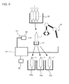
- FIG. 9 is the schematic view illustrating a part of the manufacturing line of the film covered battery 1 .
- FIG. 10 is the flowchart illustrating the flow of the screening process.
- the determination means 73 is comprised of a camera 80 , a computer 81 for image-processing picture images photographed by the camera 80 and for determining the presence or absence of a very small hollow, and a memory 82 for storing programs executed by the computer 81 and various data.
- the locomotion means 74 is comprised of a robot arm configured to operate based on a command from the computer 81 .
- Step 1 Pick up the film covered battery 1 from the common tray 70 .
- Step 2 Move the film covered battery 1 to the inspection stage 71 .
- Step 3 Take a picture of the film covered battery 1 on the inspection stage 71 by the camera 80 .
- Step 4 Image-process the photography image by the computer 81 .
- Step 5 Determine whether a very small hollow is present.
- Step 6 Determine whether the very small hollow is within predetermined regions.
- Step 7 Move to the distribution tray 72 a.
- Step 8 Move to the distribution tray 72 b.
- Step 9 Move to the distribution tray 72 c.
- the flow of the screening process is hereinafter explained in reference to FIG. 10 .
- the common tray 70 in which a plurality of film covered batteries 1 are stored, is conveyed to a predetermined position by means of a conveyance means (not shown).
- the robot arm 74 picks up any one of the film covered batteries 1 from the common tray 70 (see Step 1 ), and then moves the picked-up film covered battery 1 to the inspection stage 71 (see Step 2 ).
- a picture image of the film covered battery 1 on the inspection stage 71 is taken by the camera 80 (see Step 3 ).
- the photography image, taken by the camera 80 , is inputted into the computer 81 , and then the inputted photography image is image-processed by the computer 81 (see Step 4 ).
- the computer 81 discriminates or determines, based on the result of the image-processing, the presence or absence of a very small hollow (see Step 5 ).
- the computer 81 detects, based on brightness information within the photography image, the border (the edge) of the film covered battery 1 and a very small hollow. More concretely, within the photography image, the brightness tends to rapidly change in front and in rear of picture elements, corresponding to the border of the film covered battery 1 .
- the border of the film covered battery 1 can be detected by obtaining the picture element, whose brightness rapidly changes as compared to the picture elements adjacent to each other, and its coordinates. Furthermore, when a very small hollow is present on the surface of the film covered battery 1 , the brightness tends to rapidly change in front and in rear of the picture element, corresponding to the very small hollow. Thus, the presence or absence of a very small hollow can be detected by determining whether the picture element, whose brightness rapidly changes as compared to the picture elements adjacent to each other, is present or absent inside of the detected border of the film covered battery 1 .
- the computer 81 determines whether or not the very small hollow is present in either one of the previously-discussed first region 60 and the previously-discussed second region 62 (see Step 6 ).
- the computer 81 is configured to obtain the coordinates of the picture element, corresponding to the very small hollow, (i.e., the picture element whose brightness rapidly changes as compared to the picture elements adjacent to each other).
- region information indicating the coordinates of the boundary of the first region 60 or the coordinates of the boundary of the second region 62 , is pre-stored in the memory 82 .
- the computer 81 compares the region information read from the memory 82 with the coordinates of the picture element corresponding to the very small hollow, and then determines whether the very small hollow is present inside of the first region 60 or the second region 62 .
- Step 5 determines that a very small hollow is absent
- the film covered battery 1 is moved to the first distribution tray 72 a by the robot arm 74 (see Step 7 ).
- Step 6 determines that a very small hollow is present outside of the predetermined regions
- the film covered battery 1 is moved to the second distribution tray 72 b by the robot arm 74 (see Step 8 ).
- Step 6 determines that a very small hollow is present in the predetermined regions
- the film covered battery 1 is moved to the third distribution tray 72 c by the robot arm 74 (see Step 9 ).
- Step 6 determines that a very small hollow is present in the predetermined regions and thus the previously-discussed cover film 50 is attached to the very small hollow
- a process for determining whether the cover film 50 protrudes from the predetermined regions may be carried out as an additional process.
- size information indicating the size of cover film 50
- the computer 81 performs the above-mentioned determination based on the size information and the region information, both read from the memory 82 , and the coordinates indicating the center of the very small hollow. At this time, the above-mentioned determination is made on the assumption that the cover film 50 is attached such that the center of the cover film 50 and the center of the very small hollow coincide with each other.
- a symbol or a character, indicating the result of determination through Step 5 and the result of determination through Step 6 may be printed on the surface of the film covered battery 1 .
- an ink jet printer may be utilized.
- a symbol, indicating the result of determination has been printed, it is unnecessary to distribute, based on the result of determination, the film covered battery 1 into an appropriate one of the different distribution trays 72 a - 72 c.
- cover film may be attached to the very small hollow by means of a manipulator or the like, while using the detected coordinate data.
Landscapes
- Chemical & Material Sciences (AREA)
- General Chemical & Material Sciences (AREA)
- Chemical Kinetics & Catalysis (AREA)
- Electrochemistry (AREA)
- Engineering & Computer Science (AREA)
- Transportation (AREA)
- Mechanical Engineering (AREA)
- Manufacturing & Machinery (AREA)
- Combustion & Propulsion (AREA)
- Life Sciences & Earth Sciences (AREA)
- Sustainable Development (AREA)
- Sustainable Energy (AREA)
- Power Engineering (AREA)
- Sealing Battery Cases Or Jackets (AREA)
- Secondary Cells (AREA)
- Battery Mounting, Suspending (AREA)
Applications Claiming Priority (3)
| Application Number | Priority Date | Filing Date | Title |
|---|---|---|---|
| JP2010-239001 | 2010-12-28 | ||
| JP2010293001A JP5757730B2 (ja) | 2010-12-28 | 2010-12-28 | フィルム外装電池、電池モジュール、モジュール集合体、フィルム外装電池の製造方法、および電気自動車 |
| PCT/JP2011/078099 WO2012090652A1 (ja) | 2010-12-28 | 2011-12-05 | フィルム外装電池およびその選別方法 |
Publications (2)
| Publication Number | Publication Date |
|---|---|
| US20130284531A1 US20130284531A1 (en) | 2013-10-31 |
| US9837643B2 true US9837643B2 (en) | 2017-12-05 |
Family
ID=46382771
Family Applications (1)
| Application Number | Title | Priority Date | Filing Date |
|---|---|---|---|
| US13/976,587 Active 2032-11-22 US9837643B2 (en) | 2010-12-28 | 2011-12-05 | Film covered battery and method for screening same |
Country Status (8)
| Country | Link |
|---|---|
| US (1) | US9837643B2 (de) |
| EP (1) | EP2660892B1 (de) |
| JP (1) | JP5757730B2 (de) |
| KR (1) | KR101719030B1 (de) |
| CN (1) | CN103314465B (de) |
| BR (1) | BR112013013889A2 (de) |
| MX (1) | MX2013005979A (de) |
| WO (1) | WO2012090652A1 (de) |
Families Citing this family (23)
| Publication number | Priority date | Publication date | Assignee | Title |
|---|---|---|---|---|
| JP5757730B2 (ja) | 2010-12-28 | 2015-07-29 | オートモーティブエナジーサプライ株式会社 | フィルム外装電池、電池モジュール、モジュール集合体、フィルム外装電池の製造方法、および電気自動車 |
| WO2014141753A1 (ja) * | 2013-03-12 | 2014-09-18 | Necエナジーデバイス株式会社 | 電池モジュール |
| JP2014238958A (ja) | 2013-06-07 | 2014-12-18 | オートモーティブエナジーサプライ株式会社 | 非水系電池 |
| JPWO2015002094A1 (ja) * | 2013-07-05 | 2017-02-23 | Necエナジーデバイス株式会社 | 電池セル |
| JP5804117B2 (ja) | 2014-03-26 | 2015-11-04 | 株式会社豊田自動織機 | 蓄電装置 |
| WO2015173686A1 (en) | 2014-05-16 | 2015-11-19 | Semiconductor Energy Laboratory Co., Ltd. | Electronic device with secondary battery |
| KR102465163B1 (ko) | 2016-06-22 | 2022-11-08 | 가부시키가이샤 한도오따이 에네루기 켄큐쇼 | 전지, 및 전지의 제작 방법 |
| JP6932128B2 (ja) * | 2016-07-22 | 2021-09-08 | 株式会社エンビジョンAescジャパン | 電気化学デバイス |
| WO2018033880A2 (en) | 2016-08-17 | 2018-02-22 | Shape Corp. | Battery support and protection structure for a vehicle |
| EP3566253B1 (de) | 2017-01-04 | 2022-12-28 | Shape Corp. | Batterieträgerstruktur für ein fahrzeug |
| JP2018127250A (ja) * | 2017-02-09 | 2018-08-16 | 日産自動車株式会社 | シート貼付装置 |
| US10483510B2 (en) | 2017-05-16 | 2019-11-19 | Shape Corp. | Polarized battery tray for a vehicle |
| US11211656B2 (en) | 2017-05-16 | 2021-12-28 | Shape Corp. | Vehicle battery tray with integrated battery retention and support feature |
| WO2018213306A1 (en) | 2017-05-16 | 2018-11-22 | Shape Corp. | Vehicle battery tray having tub-based component |
| CN109216776B (zh) * | 2017-06-30 | 2022-10-25 | 远景Aesc日本有限公司 | 电化学器件 |
| WO2019055658A2 (en) | 2017-09-13 | 2019-03-21 | Shape Corp. | VEHICLE BATTERY TRAY WITH TUBULAR PERIPHERAL WALL |
| US12347879B2 (en) | 2017-09-13 | 2025-07-01 | Shape Corp. | Vehicle battery tray with tubular peripheral wall |
| CN111201155A (zh) | 2017-10-04 | 2020-05-26 | 形状集团 | 用于电动车辆的电池托盘底板组件 |
| WO2019169080A1 (en) | 2018-03-01 | 2019-09-06 | Shape Corp. | Cooling system integrated with vehicle battery tray |
| US11688910B2 (en) | 2018-03-15 | 2023-06-27 | Shape Corp. | Vehicle battery tray having tub-based component |
| CN110690408B (zh) * | 2018-07-05 | 2021-08-06 | 宁德新能源科技有限公司 | 电芯及其电池 |
| JP7246889B2 (ja) * | 2018-10-19 | 2023-03-28 | 株式会社エンビジョンAescジャパン | 組電池およびその製造方法 |
| KR102316340B1 (ko) | 2019-01-22 | 2021-10-22 | 주식회사 엘지에너지솔루션 | 전극조립체, 그를 포함하는 이차전지, 이차전지 제조방법 및 전지팩 |
Citations (13)
| Publication number | Priority date | Publication date | Assignee | Title |
|---|---|---|---|---|
| US20030017388A1 (en) * | 2001-07-23 | 2003-01-23 | Ntk Powerdex, Inc. | Packaging for polymer electrolytic cell and method of forming same |
| JP2003092132A (ja) | 2001-09-14 | 2003-03-28 | Mitsubishi Electric Corp | 電 池 |
| US20030232236A1 (en) * | 2002-06-14 | 2003-12-18 | Mitchell Porter H. | Battery package vent |
| US20040038125A1 (en) * | 2002-06-17 | 2004-02-26 | Samsung Sdi Co., Ltd. | Reinforced pouch type secondary battery |
| WO2006043760A1 (en) | 2004-10-18 | 2006-04-27 | Lg Chem, Ltd. | Secondary battery employing battery case of high strength |
| WO2006104331A1 (en) | 2005-04-01 | 2006-10-05 | Lg Chem, Ltd. | Battery pack having very thin thickness |
| JP2006294351A (ja) | 2005-04-07 | 2006-10-26 | Nec Lamilion Energy Ltd | フィルム外装電気デバイスの製造方法 |
| US20070231701A1 (en) * | 2006-03-28 | 2007-10-04 | Sang-Ho Lee | Electrode assembly and pouch type lithium rechargeable battery having the same |
| JP2007265863A (ja) | 2006-03-29 | 2007-10-11 | Nec Lamilion Energy Ltd | フィルム外装電池の製造方法 |
| JP2009043442A (ja) | 2007-08-06 | 2009-02-26 | Nec Tokin Corp | ラミネート電池の製造方法 |
| CN201681980U (zh) | 2010-05-14 | 2010-12-22 | 能元科技股份有限公司 | 可撕式电池套膜以及具有该可撕式电池套膜的电池 |
| US20110003198A1 (en) * | 2008-03-14 | 2011-01-06 | Nec Corporation | Overlaying member and film-covered electrical device |
| JP2012142144A (ja) | 2010-12-28 | 2012-07-26 | Automotive Energy Supply Corp | フィルム外装電池、電池モジュール、モジュール集合体、フィルム外装電池の選別方法および電気自動車 |
Family Cites Families (3)
| Publication number | Priority date | Publication date | Assignee | Title |
|---|---|---|---|---|
| JP4424053B2 (ja) | 2004-04-28 | 2010-03-03 | トヨタ自動車株式会社 | ラミネート型二次電池、およびその組電池 |
| KR101151110B1 (ko) * | 2007-02-21 | 2012-06-01 | 닛본 덴끼 가부시끼가이샤 | 전지 실장체, 적층 전지 어셈블리 및 필름 외장 전지 |
| JP5031606B2 (ja) * | 2008-01-30 | 2012-09-19 | ソニー株式会社 | 電池パック及びその製造方法 |
-
2010
- 2010-12-28 JP JP2010293001A patent/JP5757730B2/ja active Active
-
2011
- 2011-12-05 US US13/976,587 patent/US9837643B2/en active Active
- 2011-12-05 WO PCT/JP2011/078099 patent/WO2012090652A1/ja not_active Ceased
- 2011-12-05 BR BR112013013889A patent/BR112013013889A2/pt not_active Application Discontinuation
- 2011-12-05 MX MX2013005979A patent/MX2013005979A/es active IP Right Grant
- 2011-12-05 CN CN201180063116.4A patent/CN103314465B/zh active Active
- 2011-12-05 KR KR1020137013448A patent/KR101719030B1/ko active Active
- 2011-12-05 EP EP11852423.0A patent/EP2660892B1/de active Active
Patent Citations (16)
| Publication number | Priority date | Publication date | Assignee | Title |
|---|---|---|---|---|
| US20030017388A1 (en) * | 2001-07-23 | 2003-01-23 | Ntk Powerdex, Inc. | Packaging for polymer electrolytic cell and method of forming same |
| JP2003092132A (ja) | 2001-09-14 | 2003-03-28 | Mitsubishi Electric Corp | 電 池 |
| US20030232236A1 (en) * | 2002-06-14 | 2003-12-18 | Mitchell Porter H. | Battery package vent |
| US20040038125A1 (en) * | 2002-06-17 | 2004-02-26 | Samsung Sdi Co., Ltd. | Reinforced pouch type secondary battery |
| WO2006043760A1 (en) | 2004-10-18 | 2006-04-27 | Lg Chem, Ltd. | Secondary battery employing battery case of high strength |
| RU2331142C1 (ru) | 2004-10-18 | 2008-08-10 | Эл Джи Кем, Лтд. | Вторичная батарея с использованием высокопрочного корпуса батареи |
| RU2355070C1 (ru) | 2005-04-01 | 2009-05-10 | Эл Джи Кем, Лтд. | Аккумуляторный источник питания очень малой толщины |
| WO2006104331A1 (en) | 2005-04-01 | 2006-10-05 | Lg Chem, Ltd. | Battery pack having very thin thickness |
| JP2006294351A (ja) | 2005-04-07 | 2006-10-26 | Nec Lamilion Energy Ltd | フィルム外装電気デバイスの製造方法 |
| US20070231701A1 (en) * | 2006-03-28 | 2007-10-04 | Sang-Ho Lee | Electrode assembly and pouch type lithium rechargeable battery having the same |
| JP2007265863A (ja) | 2006-03-29 | 2007-10-11 | Nec Lamilion Energy Ltd | フィルム外装電池の製造方法 |
| JP2009043442A (ja) | 2007-08-06 | 2009-02-26 | Nec Tokin Corp | ラミネート電池の製造方法 |
| US20110003198A1 (en) * | 2008-03-14 | 2011-01-06 | Nec Corporation | Overlaying member and film-covered electrical device |
| CN201681980U (zh) | 2010-05-14 | 2010-12-22 | 能元科技股份有限公司 | 可撕式电池套膜以及具有该可撕式电池套膜的电池 |
| JP2012142144A (ja) | 2010-12-28 | 2012-07-26 | Automotive Energy Supply Corp | フィルム外装電池、電池モジュール、モジュール集合体、フィルム外装電池の選別方法および電気自動車 |
| US20130284531A1 (en) | 2010-12-28 | 2013-10-31 | Nissan Motor Co., Ltd. | Film covered battery and method for screening same |
Also Published As
| Publication number | Publication date |
|---|---|
| BR112013013889A2 (pt) | 2016-10-04 |
| CN103314465B (zh) | 2015-11-25 |
| JP5757730B2 (ja) | 2015-07-29 |
| CN103314465A (zh) | 2013-09-18 |
| JP2012142144A (ja) | 2012-07-26 |
| KR101719030B1 (ko) | 2017-03-22 |
| EP2660892A1 (de) | 2013-11-06 |
| EP2660892A4 (de) | 2016-09-07 |
| WO2012090652A1 (ja) | 2012-07-05 |
| KR20140003428A (ko) | 2014-01-09 |
| US20130284531A1 (en) | 2013-10-31 |
| EP2660892B1 (de) | 2018-08-22 |
| RU2013135414A (ru) | 2015-02-10 |
| MX2013005979A (es) | 2013-07-15 |
Similar Documents
| Publication | Publication Date | Title |
|---|---|---|
| US9837643B2 (en) | Film covered battery and method for screening same | |
| US20120219847A1 (en) | Pouch type battery and its manufacturing method | |
| EP2020695A2 (de) | Beutelartiges Batteriepack | |
| KR101624386B1 (ko) | 테이프를 이용한 전극조립체의 고정방법 | |
| JP2012142144A5 (ja) | フィルム外装電池、電池モジュール、モジュール集合体、フィルム外装電池の製造方法、および電気自動車 | |
| JP2006012835A (ja) | 二次電池 | |
| US10658631B2 (en) | Secondary battery | |
| KR102041590B1 (ko) | 플렉시블 전극 어셈블리, 및 이를 포함하는 이차 전지 | |
| KR101219252B1 (ko) | 이차 전지용 파우치 케이스 및 이를 이용한 이차 전지 | |
| KR20140103402A (ko) | 전지용 파우치, 및 이를 포함하는 파우치형 전지 | |
| US10128470B2 (en) | Rechargeable battery | |
| JP6930673B2 (ja) | 蓄電デバイス、電動自動車及び蓄電デバイスの製造方法 | |
| JP5484297B2 (ja) | 二次電池 | |
| KR102591518B1 (ko) | 배터리 팩 및 라벨 시트 | |
| CN111837284B (zh) | 电极组件、包含其的二次电池、用于制造二次电池的方法及电池组 | |
| RU2575482C2 (ru) | Заключенный в пленочную оболочку аккумулятор и способ его проверки | |
| JP4977356B2 (ja) | 電気デバイス集合体 | |
| JP2019057475A (ja) | 蓄電モジュールの製造方法及び製造装置 | |
| JP6964190B2 (ja) | 電池 | |
| TWI643386B (zh) | 電池結構 | |
| WO2025100353A1 (ja) | 電池セル | |
| SE2250971A1 (en) | Pouch battery cell system | |
| KR20250064573A (ko) | 전지 |
Legal Events
| Date | Code | Title | Description |
|---|---|---|---|
| AS | Assignment |
Owner name: AUTOMOTIVE ENERGY SUPPLY CORPORATION, JAPAN Free format text: ASSIGNMENT OF ASSIGNORS INTEREST;ASSIGNORS:OONUMA, TSUGUHIRO;MIZUTA, MASATOMO;HAYASHI, YUKO;AND OTHERS;SIGNING DATES FROM 20130415 TO 20130512;REEL/FRAME:030721/0310 Owner name: NISSAN MOTOR CO., LTD., JAPAN Free format text: ASSIGNMENT OF ASSIGNORS INTEREST;ASSIGNORS:OONUMA, TSUGUHIRO;MIZUTA, MASATOMO;HAYASHI, YUKO;AND OTHERS;SIGNING DATES FROM 20130415 TO 20130512;REEL/FRAME:030721/0310 |
|
| STCF | Information on status: patent grant |
Free format text: PATENTED CASE |
|
| AS | Assignment |
Owner name: ENVISION AESC JAPAN LTD., JAPAN Free format text: ASSIGNMENT OF ASSIGNORS INTEREST;ASSIGNOR:NISSAN MOTOR CO., LTD.;REEL/FRAME:049888/0933 Effective date: 20190725 |
|
| MAFP | Maintenance fee payment |
Free format text: PAYMENT OF MAINTENANCE FEE, 4TH YEAR, LARGE ENTITY (ORIGINAL EVENT CODE: M1551); ENTITY STATUS OF PATENT OWNER: LARGE ENTITY Year of fee payment: 4 |
|
| MAFP | Maintenance fee payment |
Free format text: PAYMENT OF MAINTENANCE FEE, 8TH YEAR, LARGE ENTITY (ORIGINAL EVENT CODE: M1552); ENTITY STATUS OF PATENT OWNER: LARGE ENTITY Year of fee payment: 8 |