EP2654477B1 - Schuh, insbesondere sportschuh - Google Patents
Schuh, insbesondere sportschuh Download PDFInfo
- Publication number
- EP2654477B1 EP2654477B1 EP11796634.1A EP11796634A EP2654477B1 EP 2654477 B1 EP2654477 B1 EP 2654477B1 EP 11796634 A EP11796634 A EP 11796634A EP 2654477 B1 EP2654477 B1 EP 2654477B1
- Authority
- EP
- European Patent Office
- Prior art keywords
- shoe
- sole element
- insole
- upper sole
- strip
- Prior art date
- Legal status (The legal status is an assumption and is not a legal conclusion. Google has not performed a legal analysis and makes no representation as to the accuracy of the status listed.)
- Not-in-force
Links
- 239000013013 elastic material Substances 0.000 claims description 11
- 238000001035 drying Methods 0.000 description 6
- 240000006829 Ficus sundaica Species 0.000 description 5
- 230000000694 effects Effects 0.000 description 4
- 244000052616 bacterial pathogen Species 0.000 description 2
- 238000009423 ventilation Methods 0.000 description 1
- XLYOFNOQVPJJNP-UHFFFAOYSA-N water Substances O XLYOFNOQVPJJNP-UHFFFAOYSA-N 0.000 description 1
Images


Classifications
-
- A—HUMAN NECESSITIES
- A43—FOOTWEAR
- A43B—CHARACTERISTIC FEATURES OF FOOTWEAR; PARTS OF FOOTWEAR
- A43B5/00—Footwear for sporting purposes
- A43B5/02—Football boots or shoes, i.e. for soccer, football or rugby
-
- A—HUMAN NECESSITIES
- A43—FOOTWEAR
- A43B—CHARACTERISTIC FEATURES OF FOOTWEAR; PARTS OF FOOTWEAR
- A43B11/00—Footwear with arrangements to facilitate putting-on or removing, e.g. with straps
-
- A—HUMAN NECESSITIES
- A43—FOOTWEAR
- A43B—CHARACTERISTIC FEATURES OF FOOTWEAR; PARTS OF FOOTWEAR
- A43B13/00—Soles; Sole-and-heel integral units
- A43B13/14—Soles; Sole-and-heel integral units characterised by the constructive form
- A43B13/18—Resilient soles
- A43B13/181—Resiliency achieved by the structure of the sole
-
- A—HUMAN NECESSITIES
- A43—FOOTWEAR
- A43B—CHARACTERISTIC FEATURES OF FOOTWEAR; PARTS OF FOOTWEAR
- A43B13/00—Soles; Sole-and-heel integral units
- A43B13/14—Soles; Sole-and-heel integral units characterised by the constructive form
- A43B13/18—Resilient soles
- A43B13/181—Resiliency achieved by the structure of the sole
- A43B13/183—Leaf springs
-
- A—HUMAN NECESSITIES
- A43—FOOTWEAR
- A43B—CHARACTERISTIC FEATURES OF FOOTWEAR; PARTS OF FOOTWEAR
- A43B17/00—Insoles for insertion, e.g. footbeds or inlays, for attachment to the shoe after the upper has been joined
- A43B17/06—Insoles for insertion, e.g. footbeds or inlays, for attachment to the shoe after the upper has been joined with metal springs
-
- A—HUMAN NECESSITIES
- A43—FOOTWEAR
- A43B—CHARACTERISTIC FEATURES OF FOOTWEAR; PARTS OF FOOTWEAR
- A43B17/00—Insoles for insertion, e.g. footbeds or inlays, for attachment to the shoe after the upper has been joined
- A43B17/10—Insoles for insertion, e.g. footbeds or inlays, for attachment to the shoe after the upper has been joined specially adapted for sweaty feet; waterproof
-
- A—HUMAN NECESSITIES
- A43—FOOTWEAR
- A43B—CHARACTERISTIC FEATURES OF FOOTWEAR; PARTS OF FOOTWEAR
- A43B17/00—Insoles for insertion, e.g. footbeds or inlays, for attachment to the shoe after the upper has been joined
- A43B17/10—Insoles for insertion, e.g. footbeds or inlays, for attachment to the shoe after the upper has been joined specially adapted for sweaty feet; waterproof
- A43B17/102—Moisture absorbing socks; Moisture dissipating socks
-
- A—HUMAN NECESSITIES
- A43—FOOTWEAR
- A43B—CHARACTERISTIC FEATURES OF FOOTWEAR; PARTS OF FOOTWEAR
- A43B7/00—Footwear with health or hygienic arrangements
- A43B7/06—Footwear with health or hygienic arrangements ventilated
Definitions
- the invention relates to a shoe, in particular a sports shoe, which has a shoe upper and a sole connected to the shoe upper, wherein the sole comprises an upper sole element and a lower sole element, wherein the upper sole element has a surface on which the intended use of the shoe Sole of the wearer of the shoe rests, wherein between the upper sole member and the lower sole member at least one spring element is effectively arranged, which is formed and arranged so that the upper sole member rests on the lower sole member by the weight of the wearer of the shoe and that at least one Part of the upper sole element lifts when not using the shoe of the lower sole member by the force of the spring element.
- Generic shoes are well known and are used for example as football boots.
- football boots which are usually wet or damp regularly, there is a risk that between the shaft bottom (ie the Insole) and the insole germs or mold, since there is no adequate ventilation.
- a shoe of the type mentioned is from the DE 620 963 C known. Comparable concepts are in the US Pat. No. 1,623,092 A , in the GB 2 041 721 A In which CN 2 057 319 U and in the US 6 131 309 A disclosed.
- the invention has for its object to develop a generic shoe so that the drying of the shoe can be done with simple means in an improved manner. This is to ensure that germs or mold can no longer form so easily. So it should be achievable an improved drying effect, which can be achieved with little economic use.
- the spring element is formed as a strip of elastic material, wherein the strip of elastic material is fastened with its one end to the shoe upper and attached at its other end to the upper sole element or wherein the strip made of elastic material is attached with its ends on the shoe upper and engages around the upper sole element.
- the proposed spring element thus has the effect that, after the shoe has been removed, an opening for the fresh air supply forms between the lower sole element and the upper sole element, which favors the drying process substantially.
- the upper sole element is preferably an insole.
- the lower sole element is preferably a midsole, on the underside of which an outsole is arranged; it can also be an insole.
- the spring element may be formed as a rubber band.
- the strip of elastic material may be fastened with its one end to the shoe upper, preferably at a height position in the upper half of the vertical extent of the shoe at the location where the strip is arranged.
- the strip of elastic material may be attached at its other end to the upper sole element. But it is also possible that the strip of elastic material is attached with its ends on the shoe upper and engages around the upper sole element.
- the strip of elastic material is preferably arranged in the heel region of the upper sole element.
- the upper sole element can be arranged pivotably in the shoe about a horizontal pivot axis lying in its toe area.
- the upper sole element lifts off at least 90% of the contact area between the upper sole element and the lower sole element when the shoe is used as intended.
- the strip-shaped portion may have a substantially rectangular shape in the plan view of the shoe. He can have a width which is between 40% and 80% of the width of the shoe in the heel area. Furthermore, it can be provided that the strip-shaped portion has a length which is between 50% and 90% of the length of the shoe.
- the proposed shoe is particularly preferably a soccer shoe.
- the idea according to the invention therefore provides that in particular the insole is pretensioned with a spring element such that the insole automatically lifts off after the shoe has been removed, thus at least partially exposing the area between the insole and the insole. Existing moisture in this area can evaporate better. Ie. through the spring element, the insole can bulge.
- this effect may be limited to only a portion of the insole (i.e., only a portion of the insole, eg, a tongue-shaped portion that rises or bulges when the shoe is removed).
- a drying of both the underside of the insole and the shaft bottom takes place in a much simpler manner.
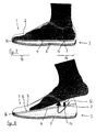
- Fig. 1 is to see a shoe 1, which is currently supported by a wearer; the foot of the wearer is designated 18.
- the sole 1 consists of an upper sole element 4 in the form of an insole and a lower sole element 5, which is generally the sole part without an insole, ie in particular a midsole the underside of an outsole is arranged.
- the insole, d. H. the upper sole element 4 has a surface 6 on which the foot 18 of the wearer rests when the shoe 1 is used.
- the insole 4 is pressed firmly against the lower sole member 5 due to the weight of the wearer, so that the in Fig. 1 outlined situation.
- a spring element 7 in the form of a spring wire clasp is effectively arranged between the upper sole element 4 and the lower sole element 5.
- the spring element 7 is designed and positioned so that the upper sole element 4 by the weight of the wearer of the shoe 1 - so while wearing the shoe - rests on the lower sole member 5 (s. Fig. 1 ); However, the shoe is not used - s. Fig. 2 the upper sole element 4 lifts over most of the contact surface existing between the upper and lower sole parts during use of the shoe.
- the upper sole element 4 is namely as in Fig. 2 apparently bulged by the spring element 7, so that air can enter into the region between the upper and lower sole part, so that moisture can evaporate improved in this area.
- the now improved air access is indicated by the arrow in Fig. 2 indicated.
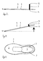
- the spring element 7 has two bends (s. Fig. 5 ); it can only be a bow; but there are also more than two bows possible.
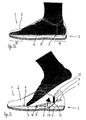
- FIGS. 7 to 11 is a variant of the proposed shoe to see.
- the insole 4 is biased by two spring elements 7 in the form of rubber bands. More precisely, on both sides of the shoe (see this Fig. 11 )
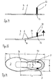
- the insole 4 is placed in the shoe so that the insole 4 about a horizontal pivot axis 16 in the toe area 15 of the shoe can pivot (shown is a direction perpendicular to the plane of the arrow direction, which marks the pivot axis). The pivoting movement is from the synopsis of FIGS. 9 and 10 seen.
- the strip-shaped portion 17 extends over a width B S , which corresponds to a part of the width B of the shoe 1 in the heel region 14, z. B. between 40% and 80% of the width B. Furthermore, the section 17 has a length L S , which corresponds to a part of the length L of the shoe 1, z. B. between 50% and 90% of the length L.
Landscapes
- Health & Medical Sciences (AREA)
- General Health & Medical Sciences (AREA)
- Physical Education & Sports Medicine (AREA)
- Epidemiology (AREA)
- Public Health (AREA)
- Footwear And Its Accessory, Manufacturing Method And Apparatuses (AREA)
Description
- Die Erfindung betrifft einen Schuh, insbesondere einen Sportschuh, der ein Schuhoberteil und eine mit dem Schuhoberteil verbundene Sohle aufweist, wobei die Sohle ein oberes Sohlenelement sowie ein unteres Sohlenelement umfasst, wobei das obere Sohlenelement eine Oberfläche aufweist, auf der bei bestimmungsgemäßer Benutzung des Schuhs die Fußsohle des Trägers des Schuhs aufliegt, wobei zwischen dem oberen Sohlenelement und dem unteren Sohlenelement mindestens ein Federelement wirksam angeordnet ist, das so ausgebildet und angeordnet ist, dass das obere Sohlenelement durch die Gewichtskraft des Trägers des Schuhs auf dem unteren Sohlenelement aufliegt und dass zumindest ein Teil des oberen Sohlenelements bei Nichtbenutzung des Schuhs von dem unteren Sohlenelement durch die Kraft des Federelements abhebt.
- Gattungsgemäße Schuhe sind allgemein bekannt und werden beispielsweise als Fußballschuhe eingesetzt. Insbesondere - aber nicht ausschließlich - beim Fußballspielen tritt häufig der Fall auf, dass Feuchtigkeit in den Schuh eindringt, wobei Wasser insbesondere in den Bereich zwischen die Einlegesohle und die Brandsohle bzw. die Zwischensohle gelangen kann. Speziell bei Fußballschuhen, die meist regelmäßig feucht bzw. nass werden, besteht somit die Gefahr, dass sich zwischen dem Schaftboden (d. h. der Brandsohle) und der Einlegesohle Keime bzw. Schimmel bilden, da keine ausreichende Belüftung vorhanden ist.
- Ein Schuh der eingangs genannten Art ist aus der
DE 620 963 C bekannt. Vergleichbare Konzepte werden in derUS 1 623 092 A , in derGB 2 041 721 A CN 2 057 319 U und in derUS 6 131 309 A offenbart. - Der Erfindung liegt die Aufgabe zugrunde, einen gattungsgemäßen Schuh so fortzubilden, dass die Trocknung des Schuhs mit einfachen Mitteln in verbesserter Weise erfolgen kann. Hiermit soll erreicht werden, dass sich Keime bzw. Schimmel nicht mehr so leicht bilden können. Es soll also ein verbesserter Trocknungseffekt erreichbar sein, der mit geringem wirtschaftlichem Einsatz zu erzielen ist.
- Die Lösung dieser Aufgabe durch die Erfindung ist dadurch gekennzeichnet, dass das Federelement als Streifen aus elastischem Material ausgebildet ist, wobei der Streifen aus elastischem Material mit seinem einen Ende am Schuhoberteil befestigt ist und mit seinem anderen Ende am oberen Sohlenelement befestigt ist oder wobei der Streifen aus elastischem Material mit seinen Enden am Schuhoberteil befestigt ist und das obere Sohlenelement umgreift.
- Das vorgeschlagene Federelement bewirkt somit, dass sich nach dem Ausziehen des Schuhs zwischen dem unteren Sohlenelement und dem oberen Sohlenelement eine Öffnung für die Frischluftzufuhr bildet, die den Trocknungsvorgang wesentlich begünstigt.
- Das obere Sohlenelement ist bevorzugt eine Einlegesohle. Das untere Sohlenelement ist bevorzugt eine Zwischensohle, an deren Unterseite eine Außensohle angeordnet ist; es kann sich auch um eine Brandsohle handeln.
- Das Federelement kann als Gummiband ausgebildet sein. Der Streifen aus elastischem Material kann dabei mit seinem einen Ende am Schuhoberteil befestigt sein, bevorzugt an einer Höhenposition in der oberen Hälfte der vertikalen Erstreckung des Schuhs an dem Ort, wo der Streifen angeordnet ist. Der Streifen aus elastischem Material kann mit seinem anderen Ende am oberen Sohlenelement befestigt sein. Möglich ist es aber auch, dass der Streifen aus elastischem Material mit seinen Enden am Schuhoberteil befestigt ist und das obere Sohlenelement umgreift. Der Streifen aus elastischem Material ist bevorzugt im Fersenbereich des oberen Sohlenelements angeordnet.
- Das obere Sohlenelement kann um eine in seinem Zehenbereich liegende horizontale Schwenkachse schwenkbar im Schuh angeordnet sein.
- Vorzugsweise hebt das obere Sohlenelement bei Nichtbenutzung des Schuhs von mindestens 90 % der bei der bestimmungsgemäßen Benutzung des Schuhs gegebenen Kontaktfläche zwischen oberem Sohlenelement und unterem Sohlenelement ab.
- Es kann aber auch vorgesehen werden, dass nur ein Teil des oberen Sohlenelements bei Nichtbenutzung des Schuhs vom unteren Sohlenelement abhebt. Hierbei kann lediglich ein streifenförmiger Abschnitt des oberen Sohlenelements bei Nichtbenutzung des Schuhs vom unteren Sohlenelement abheben. Der streifenförmige Abschnitt kann dabei in der Draufsicht auf den Schuh eine im wesentlichen rechteckige Form aufweisen. Er kann eine Breite aufweisen, die zwischen 40% und 80% der Breite des Schuhs in dessen Fersenbereich beträgt. Ferner kann vorgesehen werden, dass der streifenförmige Abschnitt eine Länge aufweist, die zwischen 50% und 90% der Länge des Schuhs beträgt.
- Der vorgeschlagene Schuh ist besonders bevorzugt ein Fußballschuh.
- Um einen verbesserten Trocknungseffekt zu erzielen, sieht die erfindungsgemäße Idee also vor, dass insbesondere die Einlegesohle mit einem Federelement derart vorgespannt wird, dass sich die Einlegesohle nach dem Ausziehen des Schuhs automatisch abhebt und so der Bereich zwischen Einlegesohle und Brandsohle zumindest teilweise freigelegt wird. Vorhandene Feuchtigkeit in diesem Bereich kann besser verdunsten. D. h. durch das Federelement kann sich die Einlegesohle aufwölben. Gegebenenfalls kann dieser Effekt auch nur auf einen Teil der Einlegesohle beschränkt werden (d. h. nur auf einen Ausschnitt der Einlegesohle, z. B. auf einen zungenförmigen Abschnitt, der sich beim Ausziehen des Schuhs erhebt bzw. sich aufwölbt). In vorteilhafter Weise erfolgt in wesentlich einfacherer Weise eine Trocknung sowohl der Unterseite der Einlegesohle als auch des Schaftbodens.
- In der Zeichnung sind Ausführungsbeispiele der Erfindung dargestellt. Es zeigen:
- Fig. 1
- die geschnitten dargestellte Seitenansicht eines nicht erfindungsgemäßen Sportschuhs, der von einem Träger benutzt wird,
- Fig. 2
- die geschnitten dargestellte Seitenansicht des Sportschuhs nach
Fig. 1 , wobei der Träger des Schuhs denselben gerade auszieht, - Fig. 3
- die Seitenansicht der Einlegesohle des Schuhs nach
Fig. 1 und 2 , wobei die Einlegesohle in der Position dargestellt ist, in der sie mit dem Gewicht des Trägers des Schuhs belastet wird, - Fig. 4
- die Draufsicht auf die Einlegesohle nach
Fig. 3 , - Fig. 5
- die Seitenansicht der Einlegesohle des Schuhs nach
Fig. 1 und 2 , wobei die Einlegesohle jetzt in der Position dargestellt ist, in der sie vom Gewicht des Trägers entlastet ist, - Fig. 6
- die Draufsicht auf die Einlegesohle nach
Fig. 5 , - Fig. 7
- die geschnitten dargestellte Seitenansicht eines Sportschuhs, der von einem Träger benutzt wird, nach einer Ausführungsform der Erfindung,
- Fig. 8
- die geschnitten dargestellte Seitenansicht des Sportschuhs nach
Fig. 7 , wobei der Träger des Schuhs denselben gerade auszieht, - Fig. 9
- die Seitenansicht der Einlegesohle des Schuhs nach
Fig. 7 und 8 , wobei die Einlegesohle in der Position dargestellt ist, in der sie mit dem Gewicht des Trägers des Schuhs belastet wird, - Fig. 10
- die Seitenansicht der Einlegesohle des Schuhs nach
Fig. 7 und 8 , wobei die Einlegesohle jetzt in der Position dargestellt ist, in der sie vom Gewicht des Trägers entlastet ist, - Fig. 11
- die Draufsicht auf den Schuh nach
Fig. 7 und 8 , - Fig. 12
- die geschnitten dargestellte Seitenansicht eines Sportschuhs, der von einem Träger benutzt wird, nach einer weiteren Ausführungsform der Erfindung,
- Fig. 13
- die geschnitten dargestellte Seitenansicht des Sportschuhs nach
Fig. 12 , wobei der Träger des Schuhs denselben gerade auszieht, - Fig. 14
- die Seitenansicht der Einlegesohle des Schuhs nach
Fig. 12 und 13 , wobei die Einlegesohle in der Position dargestellt ist, in der sie mit dem Gewicht des Trägers des Schuhs belastet wird, - Fig. 15
- die Seitenansicht der Einlegesohle des Schuhs nach
Fig. 12 und 13 , wobei die Einlegesohle jetzt in der Position dargestellt ist, in der sie vom Gewicht des Trägers entlastet ist, und - Fig. 16
- die Draufsicht auf den Schuh nach
Fig. 12 und 13 . - In
Fig. 1 ist ein Schuh 1 zu sehen, der gerade von einem Träger getragen wird; der Fuß des Trägers ist mit 18 bezeichnet. Der Schuh 1 hat ein Schuhoberteil 2 und eine unten am Schuhoberteil 2 festgelegte Sohle 3. Die Sohle besteht aus einem oberen Sohlenelement 4 in Form einer Einlegesohle und aus einem unteren Sohlenelement 5, das generell der Sohlenteil ohne Einlegesohle ist, d. h. insbesondere eine Zwischensohle, an deren Unterseite eine Außensohle angeordnet ist. - Die Einlegesohle, d. h. das obere Sohlenelement 4, hat eine Oberfläche 6, auf der der Fuß 18 des Trägers bei der Benutzung des Schuhs 1 aufliegt.
- Wird der Schuh 1 getragen, wird die Einlegesohle 4 infolge der Gewichtskraft des Trägers fest gegen das untere Sohlenelement 5 gedrückt, so dass sich die in
Fig. 1 skizzierte Situation ergibt. - Zwischen dem oberen Sohlenelement 4 und dem unteren Sohlenelement 5 ist ein Federelement 7 in Form einer Federdraht-Spange wirksam angeordnet. Das Federelement 7 ist dabei so ausgebildet und positioniert, dass das obere Sohlenelement 4 durch die Gewichtskraft des Trägers des Schuhs 1 - also während des Tragens des Schuhs - auf dem unteren Sohlenelement 5 aufliegt (s.
Fig. 1 ); wird der Schuh indes nicht benutzt - s.Fig. 2 - hebt das obere Sohlenelements 4 über den größten Teil der Kontaktfläche, die zwischen oberem und unterem Sohlenteil während der Benutzung des Schuhs vorliegt, ab. Das obere Sohlenelement 4 wird nämlich wie inFig. 2 ersichtlich durch das Federelement 7 aufgewölbt, so dass Luft in den Bereich zwischen oberem und unterem Sohlenteil eintreten kann, so dass Feuchtigkeit in diesem Bereich verbessert verdunsten kann. Der jetzt verbesserte Luftzutritt ist durch den Pfeil inFig. 2 angedeutet. - Hierzu ist das Federelement 7 an drei Verbindungsstellen 8, 9 und 10, wie es aus den
Figuren 3 bis 6 hervorgeht, mit der Einlegesohle 4 verbunden, wobei in den drei Verbindungsstellen 8, 9 und 10 Halteelemente 11 das drahtförmige Federelement 7 an der Unterseite der Einlegesohle 4 halten. Während die Einlegesohle 4 also bei Benutzung, wie inFig. 3 gesehen werden kann, flach gehalten wird, so dass sie vollständig auf dem unteren Sohlenelement 5 aufliegt, wölbt sie sich, wie ausFig. 6 hervorgeht, auf, wenn der Schuh nicht benutzt wird. - Das Federelement 7 weist zwei Bögen auf (s.
Fig. 5 ); es kann auch nur ein Bogen sein; es sind aber auch mehr als zwei Bögen möglich. - In den
Figuren 7 bis 11 ist eine Variante des vorgeschlagenen Schuhs zu sehen. Im Fersenbereich 14 des Schuhs (s.Fig. 7 ) ist die Einlegesohle 4 über zwei Federelemente 7 in Form von Gummibändern vorgespannt angeordnet. Genauer gesagt, ist an beiden Seiten des Schuhs (s. hierzuFig. 11 ) je ein Gummiband 7 befestigt, und zwar mit einem Ende 12 am Schuhoberteil 2 und mit dem anderen Ende 13 an der Einlegesohle 4. Im Zehenbereich 15 des Schuhs ist die Einlegesohle 4 so im Schuh platziert, dass die Einlegesohle 4 um eine horizontale Schwenkachse 16 schwenken kann (dargestellt ist eine sich senkrecht zur Zeichenebene erstrecke Pfeilrichtung, die die Schwenkachse markiert). Die Schwenkbewegung ist aus der Zusammenschau derFiguren 9 und 10 ersichtlich. - Wird der Schuh 1 also ausgezogen (s.
Fig. 8 ), schwenkt die Einlegesohle 4 um die Schwenkachse 16 infolge der Federkraft der beiden Federelemente 7 von der Stellung gemäßFig. 7 bzw.Fig. 9 in die Stellung gemäßFig. 8 bzw.Fig. 10 . Demgemäß wird es der Luft wieder ermöglicht (s. Pfeil inFig. 8 ), in den Bereich zwischen den Sohlenelementen 4 und 5 einzutreten und das Trocknen zu begünstigen. - Es kann auch nur ein einziges Federelement 7 in Form eines Gummibandes vorgesehen werden, dessen Enden am Schuhoberteil 2 befestigt werden und das die Einlegesohle 4 untergreift, um sie bei Nichtbelastung durch den Fuß des Trägers in die in
Fig. 8 skizzierte Stellung hochzuziehen. - Eine weitere Variante des vorgeschlagenen Schuhs ist in den
Figuren 12 bis 16 zu sehen. - Der Unterschied zu der Lösung gemäß den
Figuren 7 bis 11 besteht hier darin, dass nicht die gesamte Einlegesohle 4 mittels des Federelements 7 anhebbar ausgebildet ist, sondern dass dies nur für einen Teil der Einlegesohle 4 gilt, nämlich für einen streifenförmigen Abschnitt 17. - Der streifenförmige Abschnitt 17 erstreckt sich über eine Breite BS, die einem Teil der Breite B des Schuhs 1 in dessen Fersenbereich 14 entspricht, z. B. zwischen 40% und 80% der Breite B. Weiterhin weist der Abschnitt 17 eine Länge LS auf, die einem Teil der Länge L des Schuhs 1 entspricht, z. B. zwischen 50% und 90% der Länge L.
- Für die Anordnung des einen Federelements 7 oder der beiden Federelemente 7 (je eines an jeder Seite des Streifens 17) gilt dasselbe, wie im Zusammenhang mit dem Ausführungsbeispiel gemäß
Fig. 7 bis 11 ausgeführt. -
- 1
- Schuh
- 2
- Schuhoberteil
- 3
- Sohle
- 4
- oberes Sohlenelement (Einlegesohle)
- 5
- unteres Sohlenelement (Zwischensohle und Außensohle)
- 6
- Oberfläche
- 7
- Federelement
- 8
- Verbindungsstelle
- 9
- Verbindungsstelle
- 10
- Verbindungsstelle
- 11
- Halteelement
- 12
- Ende des Federelements
- 13
- Ende des Federelements
- 14
- Fersenbereich
- 15
- Zehenbereich
- 16
- Schwenkachse
- 17
- streifenförmiger Abschnitt
- 18
- Fuß
- BS
- Breite des streifenförmigen Abschnitts
- B
- Breite des Schuhs im Fersenbereich
- LS
- Länge des streifenförmigen Abschnitts
- L
- Länge des Schuhs
Claims (13)
- Schuh (1), insbesondere Sportschuh, der ein Schuhoberteil (2) und eine mit dem Schuhoberteil (2) verbundene Sohle (3) aufweist, wobei die Sohle (3) ein oberes Sohlenelement (4) sowie ein unteres Sohlenelement (5) umfasst, wobei das obere Sohlenelement (4) eine Oberfläche (6) aufweist, auf der bei bestimmungsgemäßer Benutzung des Schuhs (1) die Fußsohle des Trägers des Schuhs (1) aufliegt, wobei zwischen dem oberen Sohlenelement (4) und dem unteren Sohlenelement (5) mindestens ein Federelement (7) wirksam angeordnet ist, das so ausgebildet und angeordnet ist, dass das obere Sohlenelement (4) durch die Gewichtskraft des Trägers des Schuhs (1) auf dem unteren Sohlenelement (5) aufliegt und dass zumindest ein Teil des oberen Sohlenelements (4) bei Nichtbenutzung des Schuhs (1) von dem unteren Sohlenelement (5) durch die Kraft des Federelements (7) abhebt,
dadurch gekennzeichnet, dass
das Federelement (7) als Streifen aus elastischem Material ausgebildet ist,
wobei der Streifen aus elastischem Material (7) mit seinem einen Ende (12) am Schuhoberteil (2) befestigt ist und mit seinem anderen Ende (13) am oberen Sohlenelement (4) befestigt ist oder
wobei der Streifen aus elastischem Material (7) mit seinen Enden am Schuhoberteil (2) befestigt ist und das obere Sohlenelement (4) umgreift. - Schuh nach Anspruch 1, dadurch gekennzeichnet, dass das obere Sohlenelement (4) eine Einlegesohle ist.
- Schuh nach Anspruch 1 oder 2, dadurch gekennzeichnet, dass das untere Sohlenelement (5) eine Zwischensohle ist, an deren Unterseite eine Außensohle angeordnet ist.
- Schuh nach einem der Ansprüche 1 bis 3, dadurch gekennzeichnet, dass das Federelement (7) als Gummiband ausgebildet ist.
- Schuh nach einem der Ansprüche 1 bis 4, dadurch gekennzeichnet, dass der Streifen aus elastischem Material (7) im Fersenbereich (14) des oberen Sohlenelements (4) angeordnet ist.
- Schuh nach Anspruch 5, dadurch gekennzeichnet, dass das obere Sohlenelement (4) um eine in seinem Zehenbereich (15) liegende horizontale Schwenkachse (16) schwenkbar angeordnet ist.
- Schuh nach einem der Ansprüche 1 bis 6, dadurch gekennzeichnet; dass das obere Sohlenelement (4) bei Nichtbenutzung des Schuhs (1) von mindestens 90 % der bei der bestimmungsgemäßen Benutzung des Schuhs (1) gegebenen Kontaktfläche zwischen oberem Sohlenelement (4) und unterem Sohlenelement (5) abhebt.
- Schuh nach einem der Ansprüche 1 bis 6, dadurch gekennzeichnet, dass nur ein Teil des oberen Sohlenelements (4) bei Nichtbenutzung des Schuhs (1) vom unteren Sohlenelement (5) abhebt.
- Schuh nach Anspruch 8, dadurch gekennzeichnet, dass ein streifenförmiger Abschnitt (17) des oberen Sohlenelements (4) bei Nichtbenutzung des Schuhs (1) vom unteren Sohlenelement (5) abhebt.
- Schuh nach Anspruch 9, dadurch gekennzeichnet, dass der streifenförmige Abschnitt (17) in der Draufsicht auf den Schuh eine im wesentlichen rechteckige Form aufweist.
- Schuh nach Anspruch 10, dadurch gekennzeichnet, dass der streifenförmige Abschnitt (17) eine Breite (BS) aufweist, die zwischen 40% und 80% der Breite (B) des Schuhs (1) in dessen Fersenbereich (14) beträgt.
- Schuh nach Anspruch 10 oder 11, dadurch gekennzeichnet, dass der streifenförmige Abschnitt (16) eine Länge (LS) aufweist, die zwischen 50% und 90% der Länge (L) des Schuhs (1) beträgt.
- Schuh nach einem der Ansprüche 1 bis 12, dadurch gekennzeichnet, dass er ein Fußballschuh ist.
Applications Claiming Priority (2)
| Application Number | Priority Date | Filing Date | Title |
|---|---|---|---|
| DE202010016915U DE202010016915U1 (de) | 2010-12-23 | 2010-12-23 | Schuh, insbesondere Sportschuh |
| PCT/EP2011/006322 WO2012084147A1 (de) | 2010-12-23 | 2011-12-15 | Schuh, insbesondere sportschuh |
Publications (2)
| Publication Number | Publication Date |
|---|---|
| EP2654477A1 EP2654477A1 (de) | 2013-10-30 |
| EP2654477B1 true EP2654477B1 (de) | 2015-02-25 |
Family
ID=45349156
Family Applications (1)
| Application Number | Title | Priority Date | Filing Date |
|---|---|---|---|
| EP11796634.1A Not-in-force EP2654477B1 (de) | 2010-12-23 | 2011-12-15 | Schuh, insbesondere sportschuh |
Country Status (9)
| Country | Link |
|---|---|
| US (1) | US9314067B2 (de) |
| EP (1) | EP2654477B1 (de) |
| JP (1) | JP5944408B2 (de) |
| KR (1) | KR20140015304A (de) |
| CN (1) | CN103347411B (de) |
| AU (1) | AU2011348467B2 (de) |
| DE (1) | DE202010016915U1 (de) |
| ES (1) | ES2536316T3 (de) |
| WO (1) | WO2012084147A1 (de) |
Families Citing this family (38)
| Publication number | Priority date | Publication date | Assignee | Title |
|---|---|---|---|---|
| US8739432B2 (en) * | 2011-03-03 | 2014-06-03 | Stephen N. Rydinsky | Apparatus and method for drying sports pads and apparel |
| US9510635B2 (en) * | 2013-03-15 | 2016-12-06 | Nike, Inc. | Sole structures and articles of footwear having a lightweight midsole member with protective elements |
| US9301566B2 (en) | 2013-03-15 | 2016-04-05 | Nike, Inc. | Sole structures and articles of footwear having a lightweight midsole member with protective elements |
| US9504289B2 (en) | 2013-03-15 | 2016-11-29 | Nike, Inc. | Sole structures and articles of footwear having a lightweight midsole member with protective elements |
| US9750303B2 (en) | 2013-03-15 | 2017-09-05 | New Balance Athletics, Inc. | Cambered sole |
| KR101408912B1 (ko) * | 2014-03-21 | 2014-06-18 | 노태석 | 판 스프링이 구비된 줄넘기화 |
| JP1553391S (de) * | 2015-10-05 | 2016-07-04 | ||
| JP6715336B2 (ja) * | 2016-02-19 | 2020-07-01 | プーマ エス イーPuma Se | 靴、特に運動靴のインソール |
| CN115316746B (zh) | 2016-04-22 | 2024-05-28 | 飞思特知识产权有限责任公司 | 具有回弹配合系统的快速进入式鞋类 |
| CN113876075B (zh) | 2016-10-26 | 2024-07-26 | 耐克创新有限合伙公司 | 用于鞋类物品的鞋面部件 |
| WO2018081088A1 (en) | 2016-10-26 | 2018-05-03 | Nike Innovate C.V. | Hinged footwear sole structure for foot entry and method of manufacturing |
| US11304479B2 (en) | 2017-02-28 | 2022-04-19 | Nike, Inc. | Footwear with laceless fastening system |
| CN110290718B (zh) * | 2017-03-17 | 2021-11-19 | 全星有限合伙公司 | 在足部插入或取出构型与足部支撑构型之间过渡的鞋类用品 |
| US10758010B2 (en) | 2017-04-17 | 2020-09-01 | Nike, Inc. | Increased access footwear |
| CN110691532B (zh) | 2017-05-23 | 2022-04-01 | 耐克创新有限合伙公司 | 具有可移动鞋跟部分的后方进入式鞋类物品 |
| US10512298B2 (en) | 2017-05-23 | 2019-12-24 | Nike, Inc. | Footwear upper with lace-engaged zipper system |
| US10159310B2 (en) | 2017-05-25 | 2018-12-25 | Nike, Inc. | Rear closing upper for an article of footwear with front zipper to rear cord connection |
| WO2019199511A1 (en) | 2018-04-13 | 2019-10-17 | Nike Innovate C.V. | Footwear fastening system |
| US10653209B2 (en) | 2018-06-28 | 2020-05-19 | Fast Ip, Llc | Rapid-entry footwear having an actuator arm |
| CN109330083A (zh) * | 2018-12-15 | 2019-02-15 | 盐城市吉成鞋业有限公司 | 一种方便更换鞋垫的室内鞋 |
| CN109330096A (zh) * | 2018-12-15 | 2019-02-15 | 盐城市吉成鞋业有限公司 | 一种方便安装鞋垫的雪地靴 |
| CN113226099B (zh) | 2018-12-28 | 2022-11-18 | 耐克创新有限合伙公司 | 具有活动相接鞋底结构的易于进入的鞋 |
| AU2019420589B2 (en) | 2019-01-07 | 2021-05-13 | Fast Ip, Llc | Rapid-entry footwear having a compressible lattice structure |
| EP3930527B1 (de) | 2019-02-26 | 2025-09-24 | Fast IP, LLC | Schuhwerk für schnelles anziehen mit einem fersenarm und einem elastischen element |
| US11140941B2 (en) | 2019-05-03 | 2021-10-12 | Nike, Inc. | Footwear upper with unitary support frame |
| EP4640101A3 (de) | 2019-07-29 | 2025-12-24 | Fast IP, LLC | Schuh zum schnellen anziehen mit einem stabilisator und einem elastischen element |
| WO2021045902A1 (en) | 2019-09-03 | 2021-03-11 | Fast Ip, Llc | Rapid-entry footwear having a pocket for a compressed medium |
| EP4027825B1 (de) | 2019-09-09 | 2025-11-26 | Fast IP, LLC | Schuh zum schnellen anziehen, der arme zum erweitern einer öffnung aufweist |
| EP4044863B1 (de) | 2019-10-17 | 2025-10-08 | Fast IP, LLC | Schnelleinstiegsschuhe aus einem einheitlichen material |
| EP4044862B1 (de) | 2019-10-18 | 2025-06-18 | NIKE Innovate C.V. | Einfach anziehbarer schuh mit schuhbandverriegelung |
| EP4064923A1 (de) | 2019-11-25 | 2022-10-05 | NIKE Innovate C.V. | Spannhaltesystem für einen am körper tragbaren artikel |
| WO2021155058A1 (en) | 2020-01-28 | 2021-08-05 | Fast Ip, Llc | Rapid-entry footwear having rotatable straps |
| AU2021360489B2 (en) | 2020-10-13 | 2023-12-07 | Fast Ip, Llc | Rapid-entry footwear having a rotating rear portion and a fulcrum |
| EP4247207A4 (de) | 2020-11-20 | 2024-09-11 | Fast IP, LLC | Schnelleintrittsschuhwerk mit geteiltem rücken |
| AU2022221720A1 (en) | 2021-02-17 | 2023-07-27 | Fast Ip, Llc | Rapid-entry footwear having a transforming footbed |
| WO2022204444A1 (en) | 2021-03-24 | 2022-09-29 | Fast Ip, Llc | Rapid-entry footwear having a rotating tongue |
| WO2024118458A1 (en) | 2022-11-28 | 2024-06-06 | Nike Innovate C.V. | Footwear with jointed sole structure for ease of access |
| US20250374993A1 (en) * | 2024-06-06 | 2025-12-11 | Robert Wallerstein | Shoe having spring system |
Family Cites Families (42)
| Publication number | Priority date | Publication date | Assignee | Title |
|---|---|---|---|---|
| DE327846C (de) * | 1920-10-18 | Albert Daut | Unterlage mit Federspangen fuer Einlegesohlen | |
| US1194152A (en) * | 1916-08-08 | -philip faiecleugh douglas | ||
| DE620963C (de) * | 1935-10-30 | Josef Weigand | Einlegesohle | |
| US324065A (en) * | 1885-08-11 | Spring-shank for boots or shoes | ||
| US569589A (en) * | 1896-10-13 | Heel-cushion for boots or shoes | ||
| CH17016A (de) * | 1898-06-17 | 1899-03-31 | Hermann Hampel Wilhelm August | Einlegesohle |
| US673869A (en) * | 1898-07-27 | 1901-05-14 | Wilhelm August Hermann Hampel | Insole. |
| US733167A (en) * | 1902-09-08 | 1903-07-07 | John H Denton | Heel-cushion and ventilator for shoes. |
| US900920A (en) * | 1908-04-25 | 1908-10-13 | James A Foster | Heel for boots and shoes. |
| US1077871A (en) * | 1913-01-21 | 1913-11-04 | William F Connell | Instep-support. |
| FR484891A (fr) * | 1916-04-13 | 1917-11-20 | Huon Arthur Matear | Perfectionnements aux amortisseurs de chocs, pour chaussures |
| US1623092A (en) * | 1924-11-21 | 1927-04-05 | Carr Paul | Shoe |
| GB421322A (en) * | 1934-05-02 | 1934-12-18 | James Mcluskie | Improvements relating to heel pads and the like for use inside footwear |
| US2413545A (en) * | 1945-06-06 | 1946-12-31 | Cordi Leander Lee | Novelty squawk-type shoe |
| US2552711A (en) * | 1949-09-22 | 1951-05-15 | Dunker Martha | Sole to permit circulation of air in rubber footwear |
| FR1227420A (fr) * | 1959-03-06 | 1960-08-19 | Dispositif amortisseur pour chaussures | |
| US3469576A (en) * | 1966-10-05 | 1969-09-30 | Henry M Smith | Footwear |
| US3665621A (en) * | 1970-02-23 | 1972-05-30 | Ernest Colombo | Footwear |
| JPS51129235U (de) * | 1975-04-02 | 1976-10-19 | ||
| GB2041721A (en) * | 1979-02-12 | 1980-09-17 | Kerekess T T Boutaleb A | Footwear including shoehorn |
| US5311678A (en) * | 1984-01-30 | 1994-05-17 | Spademan Richard George | Shoe shock absorption system |
| US4924605A (en) * | 1985-05-22 | 1990-05-15 | Spademan Richard George | Shoe dynamic fitting and shock absorbtion system |
| US4638575A (en) * | 1986-01-13 | 1987-01-27 | Illustrato Vito J | Spring heel for shoe and the like |
| US4756095A (en) * | 1986-06-23 | 1988-07-12 | Nikola Lakic | Footwarmer for shoe |
| US4760651A (en) * | 1987-01-29 | 1988-08-02 | Pon Tzu Chi | Air-ventilating shoe pad having shoe-lift effect |
| US5010661A (en) * | 1987-12-07 | 1991-04-30 | Chu Chi Kong | Unidirectional airflow ventilating shoe and a unidirectional airflow ventilating insole for shoes |
| CN2057319U (zh) * | 1989-12-07 | 1990-05-23 | 陈汉波 | 空调鞋 |
| CN2113640U (zh) * | 1992-03-12 | 1992-08-26 | 于先则 | 一种保健鞋 |
| US5517769A (en) * | 1995-06-07 | 1996-05-21 | Zhao; Yi | Spring-loaded snap-type shoe |
| JPH10234418A (ja) * | 1997-02-28 | 1998-09-08 | Senshin:Kk | 靴内空気循環中敷 |
| US6131309A (en) * | 1998-06-04 | 2000-10-17 | Walsh; John | Shock-absorbing running shoe |
| US6029376A (en) * | 1998-12-23 | 2000-02-29 | Nike, Inc. | Article of footwear |
| DE20201427U1 (de) * | 2002-01-30 | 2003-06-12 | Puma Ag Rudolf Dassler Sport, 91074 Herzogenaurach | Schuh |
| ES1053061Y (es) * | 2002-10-28 | 2003-06-16 | Francis Raluy | Calzado con cierre automatico. |
| JP2004236860A (ja) * | 2003-02-06 | 2004-08-26 | Suminosuke Kawase | 靴べらなしで履ける履物 |
| JP2004248784A (ja) * | 2003-02-19 | 2004-09-09 | High Life Giken:Kk | 反発遅延ばね及び靴底ばね装置 |
| US7788823B2 (en) * | 2004-06-07 | 2010-09-07 | Killion David L | Full suspension footwear |
| US20060174515A1 (en) * | 2005-02-09 | 2006-08-10 | Wilkinson William T | Shoe |
| US7900376B2 (en) * | 2006-03-17 | 2011-03-08 | Mitchell Gary Rabushka | Shoe spring and shock absorbing system |
| CN2930368Y (zh) * | 2006-03-30 | 2007-08-08 | 李宁体育(上海)有限公司 | 一种鞋的可调节的减震装置 |
| CN102652588B (zh) * | 2006-04-14 | 2014-07-30 | 李家硕 | 鞋制品 |
| US20080189986A1 (en) * | 2007-02-13 | 2008-08-14 | Alexander Elnekaveh | Ventilated and resilient shoe apparatus and system |
-
2010
- 2010-12-23 DE DE202010016915U patent/DE202010016915U1/de not_active Expired - Lifetime
-
2011
- 2011-12-15 CN CN201180065827.5A patent/CN103347411B/zh not_active Expired - Fee Related
- 2011-12-15 AU AU2011348467A patent/AU2011348467B2/en not_active Ceased
- 2011-12-15 US US13/996,875 patent/US9314067B2/en not_active Expired - Fee Related
- 2011-12-15 EP EP11796634.1A patent/EP2654477B1/de not_active Not-in-force
- 2011-12-15 KR KR1020137019425A patent/KR20140015304A/ko not_active Withdrawn
- 2011-12-15 JP JP2013545084A patent/JP5944408B2/ja not_active Expired - Fee Related
- 2011-12-15 WO PCT/EP2011/006322 patent/WO2012084147A1/de not_active Ceased
- 2011-12-15 ES ES11796634.1T patent/ES2536316T3/es active Active
Also Published As
| Publication number | Publication date |
|---|---|
| KR20140015304A (ko) | 2014-02-06 |
| EP2654477A1 (de) | 2013-10-30 |
| JP5944408B2 (ja) | 2016-07-05 |
| AU2011348467B2 (en) | 2015-08-27 |
| CN103347411A (zh) | 2013-10-09 |
| CN103347411B (zh) | 2015-09-16 |
| US20130326910A1 (en) | 2013-12-12 |
| WO2012084147A1 (de) | 2012-06-28 |
| US9314067B2 (en) | 2016-04-19 |
| ES2536316T3 (es) | 2015-05-22 |
| JP2014500110A (ja) | 2014-01-09 |
| AU2011348467A1 (en) | 2013-07-11 |
| DE202010016915U1 (de) | 2012-04-02 |
Similar Documents
| Publication | Publication Date | Title |
|---|---|---|
| DE202010016915U1 (de) | Schuh, insbesondere Sportschuh | |
| DE102015202169B4 (de) | Sohle für einen Schuh | |
| DE102010040964B4 (de) | Stollen für Stollenschuh | |
| DE60019351T2 (de) | Spike für Sportschuh | |
| DE9211711U1 (de) | Schuh mit einem Zentralverschluß | |
| DE112014006390T5 (de) | Gamaschen und Steigeisen | |
| CH670939A5 (de) | ||
| DE102018122832A1 (de) | Sohlenstruktur für Schuhe und Schuhe mit dieser Sohlenstruktur | |
| WO2009153316A2 (de) | Schuh, beispielsweise hochschäftiger schuh | |
| EP3416515B1 (de) | Einlegesohle für einen schuh, insbesondere für einen sportschuh | |
| DE202015101966U1 (de) | Abdeckung für Gitterroste | |
| DD148724A5 (de) | Anordnung zum befestigen eines stiefels auf einem ski | |
| CH707064B1 (de) | Absatz für Schuh. | |
| DE1685331A1 (de) | Schuh,insbesondere Skischuh | |
| DE3907694C2 (de) | ||
| AT399287B (de) | Sohlenauflageplatte | |
| EP3375312B1 (de) | Kinderskischuh mit verbesserter gehfunktion | |
| EP0085669A1 (de) | Skischuh | |
| DE3629340A1 (de) | Sportschuh fuer laufdisziplinen | |
| DE602004000445T2 (de) | Keil, insbesondere für Sportschuhe | |
| DE102011079085A1 (de) | Schuh mit gekreuzten Klettverschlusselementen | |
| DE8530180U1 (de) | Schuh, insbesondere Schutzschuh | |
| DE202009012834U1 (de) | Laufsohle als Gehhilfe für Stiefel mit starren Sohlen sowie Bausatz zur Herstellung der Laufsohle | |
| DE202014101431U1 (de) | Gleitgerät | |
| DE449497C (de) | Schuhwerk mit Gelenkstuetze |
Legal Events
| Date | Code | Title | Description |
|---|---|---|---|
| PUAI | Public reference made under article 153(3) epc to a published international application that has entered the european phase |
Free format text: ORIGINAL CODE: 0009012 |
|
| 17P | Request for examination filed |
Effective date: 20130723 |
|
| AK | Designated contracting states |
Kind code of ref document: A1 Designated state(s): AL AT BE BG CH CY CZ DE DK EE ES FI FR GB GR HR HU IE IS IT LI LT LU LV MC MK MT NL NO PL PT RO RS SE SI SK SM TR |
|
| DAX | Request for extension of the european patent (deleted) | ||
| RIC1 | Information provided on ipc code assigned before grant |
Ipc: A43B 7/06 20060101ALI20140813BHEP Ipc: A43B 17/06 20060101ALI20140813BHEP Ipc: A43B 5/00 20060101ALI20140813BHEP Ipc: A43B 13/18 20060101ALI20140813BHEP Ipc: A43B 11/00 20060101ALI20140813BHEP Ipc: A43B 5/02 20060101AFI20140813BHEP Ipc: A43B 17/10 20060101ALI20140813BHEP |
|
| GRAP | Despatch of communication of intention to grant a patent |
Free format text: ORIGINAL CODE: EPIDOSNIGR1 |
|
| INTG | Intention to grant announced |
Effective date: 20141112 |
|
| GRAS | Grant fee paid |
Free format text: ORIGINAL CODE: EPIDOSNIGR3 |
|
| GRAA | (expected) grant |
Free format text: ORIGINAL CODE: 0009210 |
|
| AK | Designated contracting states |
Kind code of ref document: B1 Designated state(s): AL AT BE BG CH CY CZ DE DK EE ES FI FR GB GR HR HU IE IS IT LI LT LU LV MC MK MT NL NO PL PT RO RS SE SI SK SM TR |
|
| REG | Reference to a national code |
Ref country code: GB Ref legal event code: FG4D Free format text: NOT ENGLISH |
|
| REG | Reference to a national code |
Ref country code: CH Ref legal event code: EP |
|
| REG | Reference to a national code |
Ref country code: IE Ref legal event code: FG4D Free format text: LANGUAGE OF EP DOCUMENT: GERMAN |
|
| REG | Reference to a national code |
Ref country code: DE Ref legal event code: R096 Ref document number: 502011006046 Country of ref document: DE Effective date: 20150409 |
|
| REG | Reference to a national code |
Ref country code: AT Ref legal event code: REF Ref document number: 711154 Country of ref document: AT Kind code of ref document: T Effective date: 20150415 |
|
| REG | Reference to a national code |
Ref country code: ES Ref legal event code: FG2A Ref document number: 2536316 Country of ref document: ES Kind code of ref document: T3 Effective date: 20150522 |
|
| REG | Reference to a national code |
Ref country code: SE Ref legal event code: TRGR |
|
| REG | Reference to a national code |
Ref country code: NL Ref legal event code: T3 |
|
| REG | Reference to a national code |
Ref country code: LT Ref legal event code: MG4D |
|
| PG25 | Lapsed in a contracting state [announced via postgrant information from national office to epo] |
Ref country code: NO Free format text: LAPSE BECAUSE OF FAILURE TO SUBMIT A TRANSLATION OF THE DESCRIPTION OR TO PAY THE FEE WITHIN THE PRESCRIBED TIME-LIMIT Effective date: 20150525 Ref country code: LT Free format text: LAPSE BECAUSE OF FAILURE TO SUBMIT A TRANSLATION OF THE DESCRIPTION OR TO PAY THE FEE WITHIN THE PRESCRIBED TIME-LIMIT Effective date: 20150225 Ref country code: HR Free format text: LAPSE BECAUSE OF FAILURE TO SUBMIT A TRANSLATION OF THE DESCRIPTION OR TO PAY THE FEE WITHIN THE PRESCRIBED TIME-LIMIT Effective date: 20150225 Ref country code: FI Free format text: LAPSE BECAUSE OF FAILURE TO SUBMIT A TRANSLATION OF THE DESCRIPTION OR TO PAY THE FEE WITHIN THE PRESCRIBED TIME-LIMIT Effective date: 20150225 |
|
| PG25 | Lapsed in a contracting state [announced via postgrant information from national office to epo] |
Ref country code: IS Free format text: LAPSE BECAUSE OF FAILURE TO SUBMIT A TRANSLATION OF THE DESCRIPTION OR TO PAY THE FEE WITHIN THE PRESCRIBED TIME-LIMIT Effective date: 20150625 Ref country code: GR Free format text: LAPSE BECAUSE OF FAILURE TO SUBMIT A TRANSLATION OF THE DESCRIPTION OR TO PAY THE FEE WITHIN THE PRESCRIBED TIME-LIMIT Effective date: 20150526 Ref country code: RS Free format text: LAPSE BECAUSE OF FAILURE TO SUBMIT A TRANSLATION OF THE DESCRIPTION OR TO PAY THE FEE WITHIN THE PRESCRIBED TIME-LIMIT Effective date: 20150225 Ref country code: LV Free format text: LAPSE BECAUSE OF FAILURE TO SUBMIT A TRANSLATION OF THE DESCRIPTION OR TO PAY THE FEE WITHIN THE PRESCRIBED TIME-LIMIT Effective date: 20150225 |
|
| PG25 | Lapsed in a contracting state [announced via postgrant information from national office to epo] |
Ref country code: SK Free format text: LAPSE BECAUSE OF FAILURE TO SUBMIT A TRANSLATION OF THE DESCRIPTION OR TO PAY THE FEE WITHIN THE PRESCRIBED TIME-LIMIT Effective date: 20150225 Ref country code: CZ Free format text: LAPSE BECAUSE OF FAILURE TO SUBMIT A TRANSLATION OF THE DESCRIPTION OR TO PAY THE FEE WITHIN THE PRESCRIBED TIME-LIMIT Effective date: 20150225 Ref country code: EE Free format text: LAPSE BECAUSE OF FAILURE TO SUBMIT A TRANSLATION OF THE DESCRIPTION OR TO PAY THE FEE WITHIN THE PRESCRIBED TIME-LIMIT Effective date: 20150225 Ref country code: RO Free format text: LAPSE BECAUSE OF FAILURE TO SUBMIT A TRANSLATION OF THE DESCRIPTION OR TO PAY THE FEE WITHIN THE PRESCRIBED TIME-LIMIT Effective date: 20150225 Ref country code: DK Free format text: LAPSE BECAUSE OF FAILURE TO SUBMIT A TRANSLATION OF THE DESCRIPTION OR TO PAY THE FEE WITHIN THE PRESCRIBED TIME-LIMIT Effective date: 20150225 |
|
| REG | Reference to a national code |
Ref country code: DE Ref legal event code: R097 Ref document number: 502011006046 Country of ref document: DE |
|
| PG25 | Lapsed in a contracting state [announced via postgrant information from national office to epo] |
Ref country code: PL Free format text: LAPSE BECAUSE OF FAILURE TO SUBMIT A TRANSLATION OF THE DESCRIPTION OR TO PAY THE FEE WITHIN THE PRESCRIBED TIME-LIMIT Effective date: 20150225 |
|
| REG | Reference to a national code |
Ref country code: FR Ref legal event code: PLFP Year of fee payment: 5 |
|
| PLBE | No opposition filed within time limit |
Free format text: ORIGINAL CODE: 0009261 |
|
| STAA | Information on the status of an ep patent application or granted ep patent |
Free format text: STATUS: NO OPPOSITION FILED WITHIN TIME LIMIT |
|
| 26N | No opposition filed |
Effective date: 20151126 |
|
| PG25 | Lapsed in a contracting state [announced via postgrant information from national office to epo] |
Ref country code: SI Free format text: LAPSE BECAUSE OF FAILURE TO SUBMIT A TRANSLATION OF THE DESCRIPTION OR TO PAY THE FEE WITHIN THE PRESCRIBED TIME-LIMIT Effective date: 20150225 |
|
| PGFP | Annual fee paid to national office [announced via postgrant information from national office to epo] |
Ref country code: SE Payment date: 20151222 Year of fee payment: 5 Ref country code: ES Payment date: 20151218 Year of fee payment: 5 Ref country code: NL Payment date: 20151221 Year of fee payment: 5 |
|
| PG25 | Lapsed in a contracting state [announced via postgrant information from national office to epo] |
Ref country code: BE Free format text: LAPSE BECAUSE OF NON-PAYMENT OF DUE FEES Effective date: 20151231 |
|
| PG25 | Lapsed in a contracting state [announced via postgrant information from national office to epo] |
Ref country code: LU Free format text: LAPSE BECAUSE OF FAILURE TO SUBMIT A TRANSLATION OF THE DESCRIPTION OR TO PAY THE FEE WITHIN THE PRESCRIBED TIME-LIMIT Effective date: 20151215 Ref country code: MC Free format text: LAPSE BECAUSE OF FAILURE TO SUBMIT A TRANSLATION OF THE DESCRIPTION OR TO PAY THE FEE WITHIN THE PRESCRIBED TIME-LIMIT Effective date: 20150225 |
|
| REG | Reference to a national code |
Ref country code: CH Ref legal event code: PL |
|
| REG | Reference to a national code |
Ref country code: IE Ref legal event code: MM4A |
|
| PG25 | Lapsed in a contracting state [announced via postgrant information from national office to epo] |
Ref country code: IE Free format text: LAPSE BECAUSE OF NON-PAYMENT OF DUE FEES Effective date: 20151215 Ref country code: CH Free format text: LAPSE BECAUSE OF NON-PAYMENT OF DUE FEES Effective date: 20151231 Ref country code: LI Free format text: LAPSE BECAUSE OF NON-PAYMENT OF DUE FEES Effective date: 20151231 |
|
| REG | Reference to a national code |
Ref country code: FR Ref legal event code: PLFP Year of fee payment: 6 |
|
| PGFP | Annual fee paid to national office [announced via postgrant information from national office to epo] |
Ref country code: GB Payment date: 20161222 Year of fee payment: 6 |
|
| PGFP | Annual fee paid to national office [announced via postgrant information from national office to epo] |
Ref country code: FR Payment date: 20161221 Year of fee payment: 6 Ref country code: IT Payment date: 20161220 Year of fee payment: 6 |
|
| PG25 | Lapsed in a contracting state [announced via postgrant information from national office to epo] |
Ref country code: BG Free format text: LAPSE BECAUSE OF FAILURE TO SUBMIT A TRANSLATION OF THE DESCRIPTION OR TO PAY THE FEE WITHIN THE PRESCRIBED TIME-LIMIT Effective date: 20150225 Ref country code: SM Free format text: LAPSE BECAUSE OF FAILURE TO SUBMIT A TRANSLATION OF THE DESCRIPTION OR TO PAY THE FEE WITHIN THE PRESCRIBED TIME-LIMIT Effective date: 20150225 Ref country code: HU Free format text: LAPSE BECAUSE OF FAILURE TO SUBMIT A TRANSLATION OF THE DESCRIPTION OR TO PAY THE FEE WITHIN THE PRESCRIBED TIME-LIMIT; INVALID AB INITIO Effective date: 20111215 |
|
| PG25 | Lapsed in a contracting state [announced via postgrant information from national office to epo] |
Ref country code: CY Free format text: LAPSE BECAUSE OF FAILURE TO SUBMIT A TRANSLATION OF THE DESCRIPTION OR TO PAY THE FEE WITHIN THE PRESCRIBED TIME-LIMIT Effective date: 20150225 |
|
| REG | Reference to a national code |
Ref country code: SE Ref legal event code: EUG |
|
| REG | Reference to a national code |
Ref country code: NL Ref legal event code: MM Effective date: 20170101 |
|
| PG25 | Lapsed in a contracting state [announced via postgrant information from national office to epo] |
Ref country code: SE Free format text: LAPSE BECAUSE OF NON-PAYMENT OF DUE FEES Effective date: 20161216 Ref country code: MT Free format text: LAPSE BECAUSE OF FAILURE TO SUBMIT A TRANSLATION OF THE DESCRIPTION OR TO PAY THE FEE WITHIN THE PRESCRIBED TIME-LIMIT Effective date: 20150225 |
|
| PG25 | Lapsed in a contracting state [announced via postgrant information from national office to epo] |
Ref country code: NL Free format text: LAPSE BECAUSE OF NON-PAYMENT OF DUE FEES Effective date: 20170101 |
|
| REG | Reference to a national code |
Ref country code: AT Ref legal event code: MM01 Ref document number: 711154 Country of ref document: AT Kind code of ref document: T Effective date: 20161215 |
|
| PG25 | Lapsed in a contracting state [announced via postgrant information from national office to epo] |
Ref country code: ES Free format text: LAPSE BECAUSE OF NON-PAYMENT OF DUE FEES Effective date: 20161216 Ref country code: AT Free format text: LAPSE BECAUSE OF NON-PAYMENT OF DUE FEES Effective date: 20161215 |
|
| PG25 | Lapsed in a contracting state [announced via postgrant information from national office to epo] |
Ref country code: PT Free format text: LAPSE BECAUSE OF FAILURE TO SUBMIT A TRANSLATION OF THE DESCRIPTION OR TO PAY THE FEE WITHIN THE PRESCRIBED TIME-LIMIT Effective date: 20150225 Ref country code: TR Free format text: LAPSE BECAUSE OF FAILURE TO SUBMIT A TRANSLATION OF THE DESCRIPTION OR TO PAY THE FEE WITHIN THE PRESCRIBED TIME-LIMIT Effective date: 20150225 Ref country code: MK Free format text: LAPSE BECAUSE OF FAILURE TO SUBMIT A TRANSLATION OF THE DESCRIPTION OR TO PAY THE FEE WITHIN THE PRESCRIBED TIME-LIMIT Effective date: 20150225 |
|
| GBPC | Gb: european patent ceased through non-payment of renewal fee |
Effective date: 20171215 |
|
| REG | Reference to a national code |
Ref country code: FR Ref legal event code: ST Effective date: 20180831 |
|
| REG | Reference to a national code |
Ref country code: ES Ref legal event code: FD2A Effective date: 20181029 |
|
| PG25 | Lapsed in a contracting state [announced via postgrant information from national office to epo] |
Ref country code: IT Free format text: LAPSE BECAUSE OF NON-PAYMENT OF DUE FEES Effective date: 20171215 Ref country code: AL Free format text: LAPSE BECAUSE OF FAILURE TO SUBMIT A TRANSLATION OF THE DESCRIPTION OR TO PAY THE FEE WITHIN THE PRESCRIBED TIME-LIMIT Effective date: 20150225 Ref country code: FR Free format text: LAPSE BECAUSE OF NON-PAYMENT OF DUE FEES Effective date: 20180102 |
|
| PG25 | Lapsed in a contracting state [announced via postgrant information from national office to epo] |
Ref country code: GB Free format text: LAPSE BECAUSE OF NON-PAYMENT OF DUE FEES Effective date: 20171215 |
|
| PGFP | Annual fee paid to national office [announced via postgrant information from national office to epo] |
Ref country code: DE Payment date: 20181220 Year of fee payment: 8 |
|
| REG | Reference to a national code |
Ref country code: DE Ref legal event code: R119 Ref document number: 502011006046 Country of ref document: DE |
|
| PG25 | Lapsed in a contracting state [announced via postgrant information from national office to epo] |
Ref country code: DE Free format text: LAPSE BECAUSE OF NON-PAYMENT OF DUE FEES Effective date: 20200701 |