EP2654063B1 - Electromagnetic relay - Google Patents
Electromagnetic relay Download PDFInfo
- Publication number
- EP2654063B1 EP2654063B1 EP13164072.4A EP13164072A EP2654063B1 EP 2654063 B1 EP2654063 B1 EP 2654063B1 EP 13164072 A EP13164072 A EP 13164072A EP 2654063 B1 EP2654063 B1 EP 2654063B1
- Authority
- EP
- European Patent Office
- Prior art keywords
- contact
- elastic body
- electromagnetic relay
- cover
- pressing portion
- Prior art date
- Legal status (The legal status is an assumption and is not a legal conclusion. Google has not performed a legal analysis and makes no representation as to the accuracy of the status listed.)
- Active
Links
- 238000003825 pressing Methods 0.000 claims description 67
- 238000000926 separation method Methods 0.000 description 16
- 230000035939 shock Effects 0.000 description 6
- 229910045601 alloy Inorganic materials 0.000 description 5
- 239000000956 alloy Substances 0.000 description 5
- 238000010586 diagram Methods 0.000 description 4
- 238000003466 welding Methods 0.000 description 4
- 230000006870 function Effects 0.000 description 3
- 238000004519 manufacturing process Methods 0.000 description 3
- 229910007735 Zr—Si Inorganic materials 0.000 description 2
- 230000015556 catabolic process Effects 0.000 description 2
- 230000008859 change Effects 0.000 description 2
- KUNSUQLRTQLHQQ-UHFFFAOYSA-N copper tin Chemical compound [Cu].[Sn] KUNSUQLRTQLHQQ-UHFFFAOYSA-N 0.000 description 2
- 239000000463 material Substances 0.000 description 2
- 230000001105 regulatory effect Effects 0.000 description 2
- 229910000906 Bronze Inorganic materials 0.000 description 1
- 229910000881 Cu alloy Inorganic materials 0.000 description 1
- 229910017755 Cu-Sn Inorganic materials 0.000 description 1
- 229910017813 Cu—Cr Inorganic materials 0.000 description 1
- 229910017827 Cu—Fe Inorganic materials 0.000 description 1
- 229910017927 Cu—Sn Inorganic materials 0.000 description 1
- OAICVXFJPJFONN-UHFFFAOYSA-N Phosphorus Chemical compound [P] OAICVXFJPJFONN-UHFFFAOYSA-N 0.000 description 1
- 239000000853 adhesive Substances 0.000 description 1
- 230000001070 adhesive effect Effects 0.000 description 1
- 230000004075 alteration Effects 0.000 description 1
- 239000010974 bronze Substances 0.000 description 1
- 238000004140 cleaning Methods 0.000 description 1
- 239000004020 conductor Substances 0.000 description 1
- 238000006731 degradation reaction Methods 0.000 description 1
- 230000020169 heat generation Effects 0.000 description 1
- 239000012535 impurity Substances 0.000 description 1
- 238000003780 insertion Methods 0.000 description 1
- 230000037431 insertion Effects 0.000 description 1
- 230000005415 magnetization Effects 0.000 description 1
- 238000000034 method Methods 0.000 description 1
- 230000008520 organization Effects 0.000 description 1
- 230000037361 pathway Effects 0.000 description 1
- 230000008569 process Effects 0.000 description 1
- 230000003252 repetitive effect Effects 0.000 description 1
- 239000011347 resin Substances 0.000 description 1
- 229920005989 resin Polymers 0.000 description 1
- 229910000938 samarium–cobalt magnet Inorganic materials 0.000 description 1
- 238000006467 substitution reaction Methods 0.000 description 1
Images

Classifications
-
- H—ELECTRICITY
- H01—ELECTRIC ELEMENTS
- H01H—ELECTRIC SWITCHES; RELAYS; SELECTORS; EMERGENCY PROTECTIVE DEVICES
- H01H51/00—Electromagnetic relays
- H01H51/22—Polarised relays
-
- H—ELECTRICITY
- H01—ELECTRIC ELEMENTS
- H01H—ELECTRIC SWITCHES; RELAYS; SELECTORS; EMERGENCY PROTECTIVE DEVICES
- H01H1/00—Contacts
- H01H1/12—Contacts characterised by the manner in which co-operating contacts engage
- H01H1/14—Contacts characterised by the manner in which co-operating contacts engage by abutting
- H01H1/24—Contacts characterised by the manner in which co-operating contacts engage by abutting with resilient mounting
- H01H1/26—Contacts characterised by the manner in which co-operating contacts engage by abutting with resilient mounting with spring blade support
-
- H—ELECTRICITY
- H01—ELECTRIC ELEMENTS
- H01H—ELECTRIC SWITCHES; RELAYS; SELECTORS; EMERGENCY PROTECTIVE DEVICES
- H01H51/00—Electromagnetic relays
- H01H51/22—Polarised relays
- H01H51/2227—Polarised relays in which the movable part comprises at least one permanent magnet, sandwiched between pole-plates, each forming an active air-gap with parts of the stationary magnetic circuit
-
- H—ELECTRICITY
- H01—ELECTRIC ELEMENTS
- H01H—ELECTRIC SWITCHES; RELAYS; SELECTORS; EMERGENCY PROTECTIVE DEVICES
- H01H51/00—Electromagnetic relays
- H01H51/22—Polarised relays
- H01H51/2272—Polarised relays comprising rockable armature, rocking movement around central axis parallel to the main plane of the armature
- H01H51/2281—Contacts rigidly combined with armature
Definitions
- a certain aspect of the embodiments discussed herein is related to an electromagnetic relay.
- Patent Document 1 discloses an electromagnetic relay that includes a yoke capable of changing a magnetic pole thereof by an electromagnet, and an armature magnetized by a permanent magnet.
- the magnetic pole of the yoke is changed by changing the polarity of the electromagnet. This causes the armature to contact with or separate from the yoke.
- a movable contact is biased by an elastic body, and a pressing member presses the elastic body in accordance with the movement of the armature. This causes a fixing contact and the movable contact to contact with or separate from each other.
- the function as the electromagnetic relay is achieved as described above.
- a member transmitting the movement of the armature to the pressing member is formed from two or more members in Patent Document 1.
- the electromagnetic relay is hardly downsized, and production cost is difficult to be reduced.
- the elastic body is preferably made thick to reduce an electric resistance.
- the elastic constant increases as the elastic body becomes thicker.
- EP 1 968 083 A1 discloses an electromagnetic relay in accordance with the preamble of claim 1.
- An electromagnetic relay with a generally similar structure is disclosed in CH 522 285A .
- an electromagnetic relay including: a yoke capable of changing a magnetic pole thereof by an electromagnet; an armature that is magnetized by a permanent magnet and contacts with or separates from the yoke in accordance with the magnetic pole of the yoke; a movable contact that contacts with a fixing contact; an elastic body that biases the movable contact; and a pressing member that presses the elastic body in accordance with a movement of the armature to cause the movable contact to at least contact with or separate from the fixing contact, characterised in that a cover fixing the permanent magnet and the armature, and the pressing member are integrally formed.
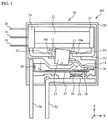
- FIG. 1 is an exploded front view of an electromagnetic relay in accordance with a first embodiment.
- FIG. 1 illustrates a side view in which a part of a base housing components is removed.
- a direction of a pair of yokes 10 is defined as an X direction
- a direction perpendicular to the X direction is defined as a Y direction
- a direction from a bottom surface to a front surface of the page is defined as a Z direction.
- the X, Y, and Z directions are indicated in the same manner in the drawings hereinafter.
- a base 50 houses an electromagnet 20, the yokes 10, armatures 12, a cover 13, a contact pressing member 16, a separation pressing member 18, a connecting member 14, a movable contact 30, a movable spring 32, a movable terminal 34, a contact spring 36, a fixing contact 40, and a fixing terminal 42.
- a coil wire 22 is wound around a bobbin 24 to form the electromagnet 20.
- a terminal 26 is electrically coupled to the coil wire.
- a pair of the yokes 10 is magnetically coupled to both sides of the electromagnet 20.
- An edge portion 10a of one of a pair of the yokes 10 has a magnetic pole opposite to that of an edge portion 10b of the other one.
- the electromagnet can change the magnetic poles of the yokes 10.
- the armatures 12 are magnetized by a permanent magnet, and contact with or separate from the yokes 10 in accordance with the magnetic poles of the yokes 10. A part of the armatures 12 and the permanent magnet (not illustrated) are fixed by the cover 13.
- the movable contact 30 is electrically coupled to the movable terminal 34 through the movable spring (elastic body) 32.
- the movable spring 32 is fixed to the movable terminal 34 by a fixing portion 39.
- the fixing contact 40 is electrically coupled to the fixing terminal 42.
- the movable contact 30 contacts with the fixing contact 40, the movable terminal 34 is electrically coupled to the fixing terminal 42.
- the movable contact 30 separates from the fixing contact 40, the movable terminal 34 is electrically disconnected with the fixing terminal 42.
- the movable contact 30 is biased by the movable spring 32 and the contact spring 36 so that the movable terminal 34 separates from the fixing terminal 42.
- the contact pressing member 16 presses the movable spring 32 and the contact spring 36 downward, the movable contact 30 contacts with the fixing contact.
- the separation pressing member 18 presses the movable spring 32 and the contact spring 36 upward, the movable contact 30 separates from the fixing contact.
- the connecting member 14 connects the cover 13 to the contact pressing member 16 and the separation pressing member 18.
- Plate-like springs such as the movable spring 32 and the contact spring 36 are described as an elastic body, but it is sufficient if the elastic body biases the movable contact 30.
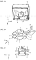
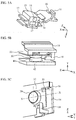
- FIG. 2A is a perspective view of the base
- FIG. 2B is a perspective view of the cover and the pressing member
- FIG. 2C is a front view of the cover.
- the base 50 includes a protrusion 52.
- the protrusion 52 function as a rotation axis 53 of the cover 13.
- the protrusion 52 has a cross section of, for example, a true circle.
- a recess portion is formed in the cover 13, and a permanent magnet 17 is located in the recess portion.
- a hole 15 is formed in the cover 13.
- the cover 13, the connecting member 14, and the pressing members 16 and 18 are integrally formed of, for example, a resin.
- the movable spring 32 and the contact spring 36 are not unified with the cover 13, the connecting member 14, and the pressing members 16 and 18, and thus can be detached from the pressing members 16 and 18.
- the first embodiment integrally forms the cover 13 and the pressing members 16 and 18.
- the cover 13 and the pressing members 16 and 18 are molded with a mold. This eliminates another member such as a card disclosed in Patent Document 1 that connects the armatures 12 to the pressing members 16 and 18.
- an electromagnetic relay 100 can be downsized. In addition, the number of components can be reduced, and thus the production cost can be reduced. Furthermore, the electromagnetic relay 100 excels in resistance to shock.
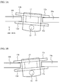
- FIG. 3A and FIG. 3B are diagrams illustrating movements of the armatures.
- the edge portion 10a of the yoke 10 has the same polarity as those of the armatures 12c and 12d and the edge portion 10b of the yoke 10 has the same polarity as those of the armatures 12a and 12b
- the armature 12a contacts with the edge portion 10a
- the armature 12d contacts with the edge portion 10b.
- the edge portion 10a has the same polarity as those of the armatures 12a and 12b and the edge portion 10b has the same polarity as those of the armatures 12c and 12d
- the armature 12c contacts with the edge portion 10a
- the armature 12b contacts with the edge portion 10b.
- a pair of the yokes 10 is provided so as to behave as described above.
- the armatures 12 are provided so as to sandwich the edge portions 10a and 10b of a pair of the yokes 10.
- the rotation of the cover 13 causes the armatures 12 to contact with or separate from the edge portions 10a and 10b. Cost can be reduced by, for example, making two armatures 12 have the identical shape.
- the hole 15 formed in the cover 13 has an oval shape.
- ⁇ 1 represents a minor axis in the X direction of the hole 15
- ⁇ 2 represents a major axis in the Y direction
- ⁇ 2 is greater than ⁇ 1 ( ⁇ 2 > ⁇ 1).
- FIG. 3A and FIG. 3B at least one of four contact points between the yokes 10 and the armatures 12 has worn, a gap is formed between the yoke 10 and the armature 12.
- gaps between the yokes 10 and the armatures 12 differ from each other depending on variability among the members.
- the yoke 10 When the gap is formed between the yoke 10 and the armature 12, the yoke 10 can not sufficiently contact with the armature 12. Thus, when the shock is applied to the electromagnetic relay 100, the yoke 10 is caused to separate from the armature 12. Therefore, the resistance to shock degrades.
- the first embodiment configures the hole 15 to have an oval shape, thus the cover 13 can easily move in the Y direction.
- the movement in the X direction is regulated.
- the above configuration allows the yokes 10 to sufficiently contact with the armatures 12 even when the gap between the yoke 10 and the armature 12 differs from other gaps at one of the contact points between the yokes 10 and the armatures 12. Thus, the degradation of the resistance to shock is suppressed.
- the movement of the cover 13 in the X direction is regulated. Therefore, the positional accuracy of the cover 13 in the X direction can be ensured.
- the protrusion may be formed in the cover 13, and the hole may be formed in the base 50.
- one of the base 50 and the cover 13 includes the hole 15 and the other one includes the protrusion 52 fitting in the hole 15 at a center of rotation of the cover 13.
- a gap between the hole 15 and the protrusion 52 in an arrangement direction of a pair of the yokes 10 is preferably narrower than that in a direction intersecting with the arrangement direction (e.g. Y direction).
- the hole 15 is not located on the center line of the yoke 10, and is located outside a pair of the armatures 12. This configuration allows the volume of the permanent magnet 17 located between the armatures 12 to be sufficiently secured, and a relay that excels in resistance to shock to be provided.
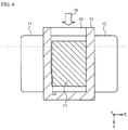
- FIG. 4 is a cross-sectional view of the cover in an XZ plane.
- the cover 13 and the pressing member are integrally molded, and the permanent magnet 17 is then inserted from an insertion opening 80.
- the permanent magnet 17 may be embedded during mold-forming.
- an equipment for magnetizing the armatures 12 is used after the mold-forming.
- the permanent magnet 17 when the permanent magnet 17 is inserted after the mold-forming, the size of the permanent magnet 17 is easily changed. Thus, the magnetization can be easily executed. Therefore, the equipment for magnetizing the armatures 12 becomes unnecessary.
- the electromagnetic relay can have variations differing in performance and cost.
- the permanent magnet 17 may be, for example, a samarium-cobalt magnet.
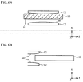
- FIG. 5A is a perspective view of the cover and the pressing member
- FIG. 5B and FIG. 5C are perspective views of the pressing member and contacts.
- the contact pressing member 16 first member
- the separation pressing member 18 second member
- the contact pressing member 16 presses the movable spring 32 toward -Y direction to cause the movable contact 30 to contact with the fixing contact 40.
- the separation pressing member 18 presses the movable spring 32 toward +Y direction to cause the movable contact 30 to separate from the fixing contact 40.
- the movable contact 30 and the fixing contact 40 are sometimes welded by inrush current.
- the separation pressing member 18 can separate the movable contact 30 from the fixing contact 40 as described above. Thus, welding failure of the contacts is suppressed.
- a distance L1 from the movable contact 30 to the contact pressing member 16 is greater than a distance L2 from the movable contact 30 to the separation pressing member 18.
- a distance from the movable spring 32 to the separation pressing member 18 when the separation pressing member 18 separates from the movable spring 32 is greater than a distance from the movable spring 32 to the contact pressing member 16 when the contact pressing member 16 separates from the movable spring 32.
- This configuration causes the separation pressing member 18 with a velocity to hit the movable spring 32 when the separation pressing member 18 contacts with the movable spring 32. This impact enables to remove the contacts from each other. Thus, the welding failure of the contacts can be further suppressed.
- the contact pressing member 16 and the separation pressing member 18 press the movable spring 32 at opposing sides with respect to line X-X (line connecting a fulcrum of the movable spring 32 to the movable contact 30).
- the above configuration further suppresses the welding failure of the contacts because the movable spring 32 is twisted after the contact pressing member 16 or the separation pressing member 18 contacts with the movable spring 32.
- the movable contact 30 slides on the fixing contact 40 in the Z direction after the fixing contact 40 contacts with the movable contact 30 or before the fixing contact 40 separates from the movable contact 30.
- impurities adhering to the surfaces of the contacts can be rubbed off. Therefore, the failure of the contact or the rise in contact resistance of the contact causing heat generation can be suppressed.
- the above configuration has a cleaning function of the contact.
- a groove 33 is located between regions of the movable spring 32 in which the contact pressing member 16 and the separation pressing member 18 contact therewith. This configuration allows an elastic constant of the movable spring 32 to be reduced. Both the contact pressing member 16 and the separation pressing member 18 are provided in the present embodiment, but it is sufficient if at least one of them is provided.
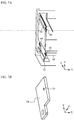
- FIG. 6A and FIG. 6B are enlarged views of the yoke and the armatures.
- FIG. 6A when the cross-sections of the armatures 12 and the yoke 10 are viewed from tips of the armatures 12, surfaces 60 of the armatures 12 facing the upper and lower surfaces of the yoke 10 bulge toward the yoke 10.
- the surfaces 60 have a curved shape so that the curvature increases at closer distances to the both sides of the armatures 12. As illustrated in FIG.
- the surfaces 60 of the armatures 12 facing the upper and lower surfaces of the yoke 10 incline so that a distance separating from the upper surface or the lower surface of the yoke 10 becomes greater at closer distances to the tips of the armatures 12.
- the surfaces 60 have a curved shape so that the curvature increases at closer distances to the tips.
- inclination of the surface 60 can increase an area of contact between the armature 12 and the yoke 10.
- the magnetic characteristics can be stabilized.
- the surface 60 having a curved shape can further stabilize the magnetic characteristics.
- FIG. 7A and FIG. 7B are perspective views of the base and the movable terminal.
- a slit 72 in which the movable terminal 34 is fitted is formed in the base 50.
- Ribs 64, 66, 68, and 69 are located in an inner surface of the base 50.
- a dowel 70 that is a protrusion is located in the movable terminal 34.
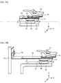
- FIG. 8A and FIG. 8B are a front view and a cross-sectional view illustrating a state where the movable terminal is fitted in, respectively.
- the movable terminal 34 is pressed into the slit 72 in the base 50 from a direction indicated with an arrow 74 in FIG. 8B .
- the rib 66 fixes the movable terminal 34 at a press rear side (-Z side) on an upper side thereof (+Y side), and the rib 64 fixes the movable terminal 34 at a press entrance side on the upper side.
- the rib 68 fixes the movable terminal 34 at the press rear side (-Z side) on a lower side thereof (-Y side), and the rib 69 fixes the movable terminal 34 at the press entrance side on the lower side.
- the movable terminal 34 are fixed at two points on each of the lower side and the upper side, and thus the movable terminal 34 can be strongly fixed. Therefore, the fabrication process such as application of adhesive can be eliminated.
- the dowel 70 provided in the movable terminal 34 allows the rib 68 to fix the movable terminal 34.
- the ribs are used to fix the movable terminal 34 in the present embodiment, but may be used to fix the fixing terminal 42.
- FIG. 9A and FIG. 9B are diagrams illustrating the movable spring and the contact spring.
- the contact spring 36 is located on the movable spring 32.
- the contact spring 36 is fixed to the movable spring 32 by a fixing portion 38 when the movable contact 30 is swaged.
- the movable spring 32 becomes a current pathway between the movable terminal 34 and the movable contact 30.
- the movable spring 32 is made of a material with a high conductivity.
- the contact spring 36 is separately provided, and thus the contact spring 36 can be made of a material with a high springiness.
- the movable spring 32 may be made of a copper alloy such as a Cu-Cr based alloy or Cu-Fe based alloy having a high conductivity.
- the contact spring 36 may be made of phosphor bronze such as a Cu-Sn based alloy with a high springiness.
- a rise in temperature of the electromagnetic relay when current is applied can be reduced.
- the resistance of the spring to the repetitive action can be improved.
- the movable spring 32 may be made of Cu-Cr-Zr-Si based alloy.
- the contact spring 36 extends close to the fixing portion 39 that fixes the movable spring 32 to the movable terminal 34.
- This configuration enables to further reduce a rise in temperature of the electromagnetic relay when current is applied.
- the electromagnetic relay illustrated in FIG. 9B reduces a rise in temperature of the fixing terminal 42 when current is applied by 5 °C compared to the electromagnetic relay illustrated in FIG. 9A .
- two or more plate-like elastic bodies such as the movable spring 32 and the contact spring 36 biasing the movable contact 30 are provided.
- the plate-like elastic bodies are fixed to each other at one point.
- the plate-like elastic bodies are not fixed to each other in a region other than the region where the plate-like elastic bodies are fixed to each other. Therefore, the springiness of the plate-like elastic body as a whole can be improved.
- the plate-like elastic bodies can be fixed at the movable contact 30.
- the elastic body fixed to the movable terminal 34 (movable spring 32) of the plate-like elastic bodies preferably has a conductivity higher than those of other elastic bodies (contact spring 36). This configuration enables to reduce an electric resistance between the movable terminal 34 and the movable contact 30. Furthermore, other elastic bodies (contact spring 36) preferably have a springiness improved more than that of the elastic body fixed to the movable terminal 34 (movable spring 32). This configuration enables to improve the springiness of the plate-like elastic bodies.
- an insulative shield wall 54 is located between the electromagnet 20 and the movable terminal 34 and the fixing terminal 42.
- This configuration can insulate the electromagnet 20 from the movable terminal 34 and the fixing terminal 42, and suppress a dielectric breakdown. Therefore, the electromagnetic relay can be downsized. Furthermore, a coil wire length and coil wire volume of the electromagnet 20 can be increased. Thus, the efficiency in the attractive force of the electromagnet can be improved, and the driving electric power of the electromagnetic relay can be reduced.
Applications Claiming Priority (1)
| Application Number | Priority Date | Filing Date | Title |
|---|---|---|---|
| JP2012095885A JP5991778B2 (ja) | 2012-04-19 | 2012-04-19 | 電磁継電器 |
Publications (2)
| Publication Number | Publication Date |
|---|---|
| EP2654063A1 EP2654063A1 (en) | 2013-10-23 |
| EP2654063B1 true EP2654063B1 (en) | 2016-09-07 |
Family
ID=48139794
Family Applications (1)
| Application Number | Title | Priority Date | Filing Date |
|---|---|---|---|
| EP13164072.4A Active EP2654063B1 (en) | 2012-04-19 | 2013-04-17 | Electromagnetic relay |
Country Status (5)
| Country | Link |
|---|---|
| US (1) | US9159515B2 (ja) |
| EP (1) | EP2654063B1 (ja) |
| JP (1) | JP5991778B2 (ja) |
| CN (1) | CN103377855B (ja) |
| TW (1) | TWI524369B (ja) |
Families Citing this family (10)
| Publication number | Priority date | Publication date | Assignee | Title |
|---|---|---|---|---|
| JP6393025B2 (ja) | 2013-07-01 | 2018-09-19 | 富士通コンポーネント株式会社 | 電磁継電器 |
| JP5835510B1 (ja) * | 2014-11-10 | 2015-12-24 | オムロン株式会社 | リレー |
| JP5954456B1 (ja) * | 2015-03-17 | 2016-07-20 | オムロン株式会社 | 不正使用検出システムおよびこれを備えた電力供給装置 |
| KR101951428B1 (ko) * | 2015-07-15 | 2019-02-22 | 엘에스산전 주식회사 | 래치 릴레이 |
| US11887797B2 (en) | 2016-10-07 | 2024-01-30 | Te Connectivity Germany Gmbh | Electrical switching element comprising a direct armature coupling |
| DE102016219529A1 (de) | 2016-10-07 | 2018-04-12 | Te Connectivity Germany Gmbh | Elektrisches Schaltelement mit unmittelbarer Ankerkopplung |
| DK3321947T3 (da) | 2016-11-15 | 2020-02-03 | Kamstrup As | Manipulationssikker bistabilt relæ til højspændinger |
| JP6376231B1 (ja) * | 2017-02-28 | 2018-08-22 | オムロン株式会社 | 電磁継電器およびスマートメータ |
| JP2019032945A (ja) * | 2017-08-04 | 2019-02-28 | オムロン株式会社 | 電磁継電器 |
| DE102018109864B4 (de) * | 2018-04-24 | 2021-09-02 | Phoenix Contact Gmbh & Co. Kg | Relais |
Family Cites Families (35)
| Publication number | Priority date | Publication date | Assignee | Title |
|---|---|---|---|---|
| US3387240A (en) * | 1966-05-31 | 1968-06-04 | Automatic Elect Lab | Reed relay with mounting for protecting encapsulated switches and for positioning bias magnets |
| US3418610A (en) * | 1966-08-26 | 1968-12-24 | John S. Hammond | Magnetic reed switch |
| CH522285A (de) | 1970-02-20 | 1972-06-15 | Zellweger Uster Ag | Stromstoss-Schalter |
| JPS52153073U (ja) * | 1976-05-15 | 1977-11-19 | ||
| JPS5634695Y2 (ja) * | 1977-01-31 | 1981-08-15 | ||
| DE2723430C2 (de) * | 1977-05-24 | 1984-04-26 | Siemens AG, 1000 Berlin und 8000 München | Elektromagnetisches Relais |
| JPS5622024A (en) * | 1979-07-31 | 1981-03-02 | Matsushita Electric Works Ltd | Switch for electromagnetic relay |
| JPS5697932A (en) * | 1979-12-30 | 1981-08-07 | Matsushita Electric Works Ltd | Electromagnetic relay |
| AU565375B2 (en) * | 1984-07-25 | 1987-09-10 | Matsushita Electric Works Ltd. | Polarized electromagnetic relay |
| US4688010A (en) * | 1984-12-22 | 1987-08-18 | Matsushita Electric Works, Ltd. | Electromagnetic relay |
| JPS61218025A (ja) * | 1985-03-25 | 1986-09-27 | 松下電工株式会社 | 有極リレ− |
| JPS61267220A (ja) | 1985-05-20 | 1986-11-26 | 松下電工株式会社 | 有極リレ− |
| US4668928A (en) * | 1986-06-23 | 1987-05-26 | Tektronix, Inc. | Bi-stable switch with pivoted armature |
| JPS6332820A (ja) * | 1986-07-25 | 1988-02-12 | オムロン株式会社 | 有極電磁継電器 |
| US4843360A (en) * | 1987-02-05 | 1989-06-27 | Takamisawa Electric Co., Ltd. | Polarized electromagnetic relay |
| JPH0338690A (ja) | 1989-07-05 | 1991-02-19 | Nec Shizuoka Ltd | データ処理装置 |
| DE9208114U1 (ja) | 1991-06-28 | 1992-10-08 | W. Gruner Gmbh Relaisfabrik, 7209 Wehingen, De | |
| JP2580919B2 (ja) | 1991-12-13 | 1997-02-12 | 株式会社豊田自動織機製作所 | 床面清掃車 |
| JPH06236725A (ja) | 1993-02-10 | 1994-08-23 | Omron Corp | 電磁継電器 |
| JP3472881B2 (ja) | 1993-02-24 | 2003-12-02 | オムロン株式会社 | 電磁継電器の製造方法 |
| JP3829392B2 (ja) | 1997-03-07 | 2006-10-04 | オムロン株式会社 | 電磁継電器 |
| DE19715261C1 (de) * | 1997-04-12 | 1998-12-10 | Gruner Ag | Relais |
| US5994987A (en) * | 1998-05-15 | 1999-11-30 | Siemens Energy & Automation, Inc. | Contact mechanism for electronic overload relays |
| JP2000311570A (ja) | 1999-04-28 | 2000-11-07 | Nec Corp | 電磁リレー |
| JP3876576B2 (ja) | 1999-10-26 | 2007-01-31 | 松下電工株式会社 | 電磁リレー |
| WO2001048778A1 (fr) | 1999-12-24 | 2001-07-05 | Takamisawa Electric Co., Ltd. | Relais polaire |
| JP3985645B2 (ja) | 2002-09-27 | 2007-10-03 | オムロン株式会社 | 電磁継電器 |
| JP4241607B2 (ja) | 2004-12-22 | 2009-03-18 | パナソニック電工株式会社 | 電磁リレー |
| DE102007011328A1 (de) | 2007-03-08 | 2008-09-11 | Gruner Ag | Relais |
| US7659800B2 (en) | 2007-08-01 | 2010-02-09 | Philipp Gruner | Electromagnetic relay assembly |
| DE102008057555B4 (de) * | 2008-11-15 | 2010-08-12 | Tyco Electronics Austria Gmbh | Relais mit Flip-Flop-Feder |
| US8203403B2 (en) * | 2009-08-27 | 2012-06-19 | Tyco Electronics Corporation | Electrical switching devices having moveable terminals |
| US8222982B2 (en) * | 2009-12-28 | 2012-07-17 | Schneider Electric USA, Inc. | Overload relay trip mechanism |
| US8564386B2 (en) * | 2011-01-18 | 2013-10-22 | Tyco Electronics Corporation | Electrical switching device |
| US8222981B1 (en) * | 2011-01-18 | 2012-07-17 | Tyco Electronics Corporation | Electrical switching device |
-
2012
- 2012-04-19 JP JP2012095885A patent/JP5991778B2/ja active Active
-
2013
- 2013-04-03 US US13/855,998 patent/US9159515B2/en active Active
- 2013-04-16 TW TW102113514A patent/TWI524369B/zh active
- 2013-04-17 EP EP13164072.4A patent/EP2654063B1/en active Active
- 2013-04-19 CN CN201310136452.8A patent/CN103377855B/zh active Active
Also Published As
| Publication number | Publication date |
|---|---|
| TWI524369B (zh) | 2016-03-01 |
| CN103377855A (zh) | 2013-10-30 |
| US20130278362A1 (en) | 2013-10-24 |
| US9159515B2 (en) | 2015-10-13 |
| CN103377855B (zh) | 2015-11-04 |
| JP5991778B2 (ja) | 2016-09-14 |
| EP2654063A1 (en) | 2013-10-23 |
| TW201351465A (zh) | 2013-12-16 |
| JP2013222699A (ja) | 2013-10-28 |
Similar Documents
| Publication | Publication Date | Title |
|---|---|---|
| EP2654063B1 (en) | Electromagnetic relay | |
| US8847714B2 (en) | Relay | |
| US9013253B2 (en) | Relay | |
| EP2533262B1 (en) | Electromagnetic relay and method of manufacturing the same | |
| US9412545B2 (en) | Electromagnetic relay | |
| US9305718B2 (en) | Electromagnetic relay | |
| US20100207713A1 (en) | Electromagnetic relay | |
| EP2919252B1 (en) | Electromagnetic relay | |
| JP2017068926A (ja) | 電磁継電器 | |
| JP5427492B2 (ja) | 電磁継電器 | |
| JP5549642B2 (ja) | 継電器 | |
| CN115836375A (zh) | 电磁继电器 | |
| CN112582218A (zh) | 继电器 | |
| US11615931B2 (en) | Electromagnetic relay and electromagnetic device | |
| CN108140516B (zh) | 电磁继电器 | |
| CN210325649U (zh) | 触头装置和具有该触头装置的接触器 | |
| KR102197518B1 (ko) | 전자 접촉기 | |
| JP6732986B2 (ja) | 電磁継電器 | |
| JP6726156B2 (ja) | 電磁継電器 | |
| EP4261868A1 (en) | Contact apparatus and electromagnetic relay | |
| CN117174534A (zh) | 引出结构及磁保持继电器 | |
| JP5546932B2 (ja) | 電磁継電器 |
Legal Events
| Date | Code | Title | Description |
|---|---|---|---|
| PUAI | Public reference made under article 153(3) epc to a published international application that has entered the european phase |
Free format text: ORIGINAL CODE: 0009012 |
|
| AK | Designated contracting states |
Kind code of ref document: A1 Designated state(s): AL AT BE BG CH CY CZ DE DK EE ES FI FR GB GR HR HU IE IS IT LI LT LU LV MC MK MT NL NO PL PT RO RS SE SI SK SM TR |
|
| AX | Request for extension of the european patent |
Extension state: BA ME |
|
| 17P | Request for examination filed |
Effective date: 20140217 |
|
| RBV | Designated contracting states (corrected) |
Designated state(s): AL AT BE BG CH CY CZ DE DK EE ES FI FR GB GR HR HU IE IS IT LI LT LU LV MC MK MT NL NO PL PT RO RS SE SI SK SM TR |
|
| RIC1 | Information provided on ipc code assigned before grant |
Ipc: H01H 51/22 20060101AFI20150929BHEP Ipc: H01H 1/26 20060101ALI20150929BHEP |
|
| GRAP | Despatch of communication of intention to grant a patent |
Free format text: ORIGINAL CODE: EPIDOSNIGR1 |
|
| INTG | Intention to grant announced |
Effective date: 20151117 |
|
| RIN1 | Information on inventor provided before grant (corrected) |
Inventor name: YUBA, TAKASHI Inventor name: IWAMOTO, DAIEI |
|
| RAP1 | Party data changed (applicant data changed or rights of an application transferred) |
Owner name: FUJITSU COMPONENT LIMITED |
|
| GRAP | Despatch of communication of intention to grant a patent |
Free format text: ORIGINAL CODE: EPIDOSNIGR1 |
|
| GRAS | Grant fee paid |
Free format text: ORIGINAL CODE: EPIDOSNIGR3 |
|
| INTG | Intention to grant announced |
Effective date: 20160502 |
|
| GRAA | (expected) grant |
Free format text: ORIGINAL CODE: 0009210 |
|
| AK | Designated contracting states |
Kind code of ref document: B1 Designated state(s): AL AT BE BG CH CY CZ DE DK EE ES FI FR GB GR HR HU IE IS IT LI LT LU LV MC MK MT NL NO PL PT RO RS SE SI SK SM TR |
|
| REG | Reference to a national code |
Ref country code: GB Ref legal event code: FG4D |
|
| REG | Reference to a national code |
Ref country code: CH Ref legal event code: EP |
|
| REG | Reference to a national code |
Ref country code: IE Ref legal event code: FG4D |
|
| REG | Reference to a national code |
Ref country code: AT Ref legal event code: REF Ref document number: 827522 Country of ref document: AT Kind code of ref document: T Effective date: 20161015 |
|
| REG | Reference to a national code |
Ref country code: DE Ref legal event code: R096 Ref document number: 602013011033 Country of ref document: DE |
|
| REG | Reference to a national code |
Ref country code: LT Ref legal event code: MG4D |
|
| REG | Reference to a national code |
Ref country code: NL Ref legal event code: MP Effective date: 20160907 |
|
| PG25 | Lapsed in a contracting state [announced via postgrant information from national office to epo] |
Ref country code: LT Free format text: LAPSE BECAUSE OF FAILURE TO SUBMIT A TRANSLATION OF THE DESCRIPTION OR TO PAY THE FEE WITHIN THE PRESCRIBED TIME-LIMIT Effective date: 20160907 Ref country code: FI Free format text: LAPSE BECAUSE OF FAILURE TO SUBMIT A TRANSLATION OF THE DESCRIPTION OR TO PAY THE FEE WITHIN THE PRESCRIBED TIME-LIMIT Effective date: 20160907 Ref country code: RS Free format text: LAPSE BECAUSE OF FAILURE TO SUBMIT A TRANSLATION OF THE DESCRIPTION OR TO PAY THE FEE WITHIN THE PRESCRIBED TIME-LIMIT Effective date: 20160907 Ref country code: NO Free format text: LAPSE BECAUSE OF FAILURE TO SUBMIT A TRANSLATION OF THE DESCRIPTION OR TO PAY THE FEE WITHIN THE PRESCRIBED TIME-LIMIT Effective date: 20161207 Ref country code: HR Free format text: LAPSE BECAUSE OF FAILURE TO SUBMIT A TRANSLATION OF THE DESCRIPTION OR TO PAY THE FEE WITHIN THE PRESCRIBED TIME-LIMIT Effective date: 20160907 |
|
| REG | Reference to a national code |
Ref country code: AT Ref legal event code: MK05 Ref document number: 827522 Country of ref document: AT Kind code of ref document: T Effective date: 20160907 |
|
| PG25 | Lapsed in a contracting state [announced via postgrant information from national office to epo] |
Ref country code: NL Free format text: LAPSE BECAUSE OF FAILURE TO SUBMIT A TRANSLATION OF THE DESCRIPTION OR TO PAY THE FEE WITHIN THE PRESCRIBED TIME-LIMIT Effective date: 20160907 Ref country code: SE Free format text: LAPSE BECAUSE OF FAILURE TO SUBMIT A TRANSLATION OF THE DESCRIPTION OR TO PAY THE FEE WITHIN THE PRESCRIBED TIME-LIMIT Effective date: 20160907 Ref country code: ES Free format text: LAPSE BECAUSE OF FAILURE TO SUBMIT A TRANSLATION OF THE DESCRIPTION OR TO PAY THE FEE WITHIN THE PRESCRIBED TIME-LIMIT Effective date: 20160907 Ref country code: GR Free format text: LAPSE BECAUSE OF FAILURE TO SUBMIT A TRANSLATION OF THE DESCRIPTION OR TO PAY THE FEE WITHIN THE PRESCRIBED TIME-LIMIT Effective date: 20161208 Ref country code: LV Free format text: LAPSE BECAUSE OF FAILURE TO SUBMIT A TRANSLATION OF THE DESCRIPTION OR TO PAY THE FEE WITHIN THE PRESCRIBED TIME-LIMIT Effective date: 20160907 |
|
| REG | Reference to a national code |
Ref country code: FR Ref legal event code: PLFP Year of fee payment: 5 |
|
| PG25 | Lapsed in a contracting state [announced via postgrant information from national office to epo] |
Ref country code: RO Free format text: LAPSE BECAUSE OF FAILURE TO SUBMIT A TRANSLATION OF THE DESCRIPTION OR TO PAY THE FEE WITHIN THE PRESCRIBED TIME-LIMIT Effective date: 20160907 Ref country code: EE Free format text: LAPSE BECAUSE OF FAILURE TO SUBMIT A TRANSLATION OF THE DESCRIPTION OR TO PAY THE FEE WITHIN THE PRESCRIBED TIME-LIMIT Effective date: 20160907 |
|
| PG25 | Lapsed in a contracting state [announced via postgrant information from national office to epo] |
Ref country code: SM Free format text: LAPSE BECAUSE OF FAILURE TO SUBMIT A TRANSLATION OF THE DESCRIPTION OR TO PAY THE FEE WITHIN THE PRESCRIBED TIME-LIMIT Effective date: 20160907 Ref country code: PT Free format text: LAPSE BECAUSE OF FAILURE TO SUBMIT A TRANSLATION OF THE DESCRIPTION OR TO PAY THE FEE WITHIN THE PRESCRIBED TIME-LIMIT Effective date: 20170109 Ref country code: AT Free format text: LAPSE BECAUSE OF FAILURE TO SUBMIT A TRANSLATION OF THE DESCRIPTION OR TO PAY THE FEE WITHIN THE PRESCRIBED TIME-LIMIT Effective date: 20160907 Ref country code: PL Free format text: LAPSE BECAUSE OF FAILURE TO SUBMIT A TRANSLATION OF THE DESCRIPTION OR TO PAY THE FEE WITHIN THE PRESCRIBED TIME-LIMIT Effective date: 20160907 Ref country code: CZ Free format text: LAPSE BECAUSE OF FAILURE TO SUBMIT A TRANSLATION OF THE DESCRIPTION OR TO PAY THE FEE WITHIN THE PRESCRIBED TIME-LIMIT Effective date: 20160907 Ref country code: SK Free format text: LAPSE BECAUSE OF FAILURE TO SUBMIT A TRANSLATION OF THE DESCRIPTION OR TO PAY THE FEE WITHIN THE PRESCRIBED TIME-LIMIT Effective date: 20160907 Ref country code: IS Free format text: LAPSE BECAUSE OF FAILURE TO SUBMIT A TRANSLATION OF THE DESCRIPTION OR TO PAY THE FEE WITHIN THE PRESCRIBED TIME-LIMIT Effective date: 20170107 Ref country code: BE Free format text: LAPSE BECAUSE OF FAILURE TO SUBMIT A TRANSLATION OF THE DESCRIPTION OR TO PAY THE FEE WITHIN THE PRESCRIBED TIME-LIMIT Effective date: 20160907 Ref country code: BG Free format text: LAPSE BECAUSE OF FAILURE TO SUBMIT A TRANSLATION OF THE DESCRIPTION OR TO PAY THE FEE WITHIN THE PRESCRIBED TIME-LIMIT Effective date: 20161207 |
|
| REG | Reference to a national code |
Ref country code: DE Ref legal event code: R097 Ref document number: 602013011033 Country of ref document: DE |
|
| PG25 | Lapsed in a contracting state [announced via postgrant information from national office to epo] |
Ref country code: IT Free format text: LAPSE BECAUSE OF FAILURE TO SUBMIT A TRANSLATION OF THE DESCRIPTION OR TO PAY THE FEE WITHIN THE PRESCRIBED TIME-LIMIT Effective date: 20160907 |
|
| PLBE | No opposition filed within time limit |
Free format text: ORIGINAL CODE: 0009261 |
|
| STAA | Information on the status of an ep patent application or granted ep patent |
Free format text: STATUS: NO OPPOSITION FILED WITHIN TIME LIMIT |
|
| PG25 | Lapsed in a contracting state [announced via postgrant information from national office to epo] |
Ref country code: DK Free format text: LAPSE BECAUSE OF FAILURE TO SUBMIT A TRANSLATION OF THE DESCRIPTION OR TO PAY THE FEE WITHIN THE PRESCRIBED TIME-LIMIT Effective date: 20160907 |
|
| 26N | No opposition filed |
Effective date: 20170608 |
|
| PG25 | Lapsed in a contracting state [announced via postgrant information from national office to epo] |
Ref country code: SI Free format text: LAPSE BECAUSE OF FAILURE TO SUBMIT A TRANSLATION OF THE DESCRIPTION OR TO PAY THE FEE WITHIN THE PRESCRIBED TIME-LIMIT Effective date: 20160907 |
|
| REG | Reference to a national code |
Ref country code: CH Ref legal event code: PL |
|
| REG | Reference to a national code |
Ref country code: IE Ref legal event code: MM4A |
|
| PG25 | Lapsed in a contracting state [announced via postgrant information from national office to epo] |
Ref country code: MC Free format text: LAPSE BECAUSE OF FAILURE TO SUBMIT A TRANSLATION OF THE DESCRIPTION OR TO PAY THE FEE WITHIN THE PRESCRIBED TIME-LIMIT Effective date: 20160907 |
|
| PG25 | Lapsed in a contracting state [announced via postgrant information from national office to epo] |
Ref country code: LU Free format text: LAPSE BECAUSE OF NON-PAYMENT OF DUE FEES Effective date: 20170417 Ref country code: CH Free format text: LAPSE BECAUSE OF NON-PAYMENT OF DUE FEES Effective date: 20170430 Ref country code: LI Free format text: LAPSE BECAUSE OF NON-PAYMENT OF DUE FEES Effective date: 20170430 |
|
| REG | Reference to a national code |
Ref country code: FR Ref legal event code: PLFP Year of fee payment: 6 |
|
| PG25 | Lapsed in a contracting state [announced via postgrant information from national office to epo] |
Ref country code: IE Free format text: LAPSE BECAUSE OF NON-PAYMENT OF DUE FEES Effective date: 20170417 |
|
| PG25 | Lapsed in a contracting state [announced via postgrant information from national office to epo] |
Ref country code: MT Free format text: LAPSE BECAUSE OF NON-PAYMENT OF DUE FEES Effective date: 20170417 |
|
| PG25 | Lapsed in a contracting state [announced via postgrant information from national office to epo] |
Ref country code: AL Free format text: LAPSE BECAUSE OF FAILURE TO SUBMIT A TRANSLATION OF THE DESCRIPTION OR TO PAY THE FEE WITHIN THE PRESCRIBED TIME-LIMIT Effective date: 20160907 |
|
| PG25 | Lapsed in a contracting state [announced via postgrant information from national office to epo] |
Ref country code: HU Free format text: LAPSE BECAUSE OF FAILURE TO SUBMIT A TRANSLATION OF THE DESCRIPTION OR TO PAY THE FEE WITHIN THE PRESCRIBED TIME-LIMIT; INVALID AB INITIO Effective date: 20130417 |
|
| PG25 | Lapsed in a contracting state [announced via postgrant information from national office to epo] |
Ref country code: CY Free format text: LAPSE BECAUSE OF NON-PAYMENT OF DUE FEES Effective date: 20160907 |
|
| PG25 | Lapsed in a contracting state [announced via postgrant information from national office to epo] |
Ref country code: MK Free format text: LAPSE BECAUSE OF FAILURE TO SUBMIT A TRANSLATION OF THE DESCRIPTION OR TO PAY THE FEE WITHIN THE PRESCRIBED TIME-LIMIT Effective date: 20160907 |
|
| PG25 | Lapsed in a contracting state [announced via postgrant information from national office to epo] |
Ref country code: TR Free format text: LAPSE BECAUSE OF FAILURE TO SUBMIT A TRANSLATION OF THE DESCRIPTION OR TO PAY THE FEE WITHIN THE PRESCRIBED TIME-LIMIT Effective date: 20160907 |
|
| REG | Reference to a national code |
Ref country code: DE Ref legal event code: R082 Ref document number: 602013011033 Country of ref document: DE Representative=s name: HL KEMPNER PATENTANWAELTE, SOLICITORS (ENGLAND, DE Ref country code: DE Ref legal event code: R082 Ref document number: 602013011033 Country of ref document: DE Representative=s name: HL KEMPNER PATENTANWALT, RECHTSANWALT, SOLICIT, DE |
|
| PGFP | Annual fee paid to national office [announced via postgrant information from national office to epo] |
Ref country code: FR Payment date: 20230309 Year of fee payment: 11 |
|
| PGFP | Annual fee paid to national office [announced via postgrant information from national office to epo] |
Ref country code: GB Payment date: 20230302 Year of fee payment: 11 |
|
| PGFP | Annual fee paid to national office [announced via postgrant information from national office to epo] |
Ref country code: DE Payment date: 20230228 Year of fee payment: 11 |