EP2653639B1 - Serrure de véhicule électrique - Google Patents
Serrure de véhicule électrique Download PDFInfo
- Publication number
- EP2653639B1 EP2653639B1 EP20120164511 EP12164511A EP2653639B1 EP 2653639 B1 EP2653639 B1 EP 2653639B1 EP 20120164511 EP20120164511 EP 20120164511 EP 12164511 A EP12164511 A EP 12164511A EP 2653639 B1 EP2653639 B1 EP 2653639B1
- Authority
- EP
- European Patent Office
- Prior art keywords
- ratchet
- lever
- latch
- release
- auxiliary
- Prior art date
- Legal status (The legal status is an assumption and is not a legal conclusion. Google has not performed a legal analysis and makes no representation as to the accuracy of the status listed.)
- Active
Links
Images


Classifications
-
- E—FIXED CONSTRUCTIONS
- E05—LOCKS; KEYS; WINDOW OR DOOR FITTINGS; SAFES
- E05B—LOCKS; ACCESSORIES THEREFOR; HANDCUFFS
- E05B81/00—Power-actuated vehicle locks
- E05B81/12—Power-actuated vehicle locks characterised by the function or purpose of the powered actuators
- E05B81/16—Power-actuated vehicle locks characterised by the function or purpose of the powered actuators operating on locking elements for locking or unlocking action
-
- E—FIXED CONSTRUCTIONS
- E05—LOCKS; KEYS; WINDOW OR DOOR FITTINGS; SAFES
- E05B—LOCKS; ACCESSORIES THEREFOR; HANDCUFFS
- E05B77/00—Vehicle locks characterised by special functions or purposes
- E05B77/34—Protection against weather or dirt, e.g. against water ingress
-
- E—FIXED CONSTRUCTIONS
- E05—LOCKS; KEYS; WINDOW OR DOOR FITTINGS; SAFES
- E05B—LOCKS; ACCESSORIES THEREFOR; HANDCUFFS
- E05B77/00—Vehicle locks characterised by special functions or purposes
- E05B77/14—Specially controlled locking actions in case of open doors or in case of doors moved from an open to a closed position, e.g. lock-out prevention or self-cancelling
- E05B77/16—Preventing locking with the bolt in the unlatched position, i.e. when the door is open
-
- E—FIXED CONSTRUCTIONS
- E05—LOCKS; KEYS; WINDOW OR DOOR FITTINGS; SAFES
- E05B—LOCKS; ACCESSORIES THEREFOR; HANDCUFFS
- E05B81/00—Power-actuated vehicle locks
- E05B81/02—Power-actuated vehicle locks characterised by the type of actuators used
- E05B81/04—Electrical
- E05B81/06—Electrical using rotary motors
-
- E—FIXED CONSTRUCTIONS
- E05—LOCKS; KEYS; WINDOW OR DOOR FITTINGS; SAFES
- E05B—LOCKS; ACCESSORIES THEREFOR; HANDCUFFS
- E05B81/00—Power-actuated vehicle locks
- E05B81/12—Power-actuated vehicle locks characterised by the function or purpose of the powered actuators
- E05B81/14—Power-actuated vehicle locks characterised by the function or purpose of the powered actuators operating on bolt detents, e.g. for unlatching the bolt
-
- E—FIXED CONSTRUCTIONS
- E05—LOCKS; KEYS; WINDOW OR DOOR FITTINGS; SAFES
- E05B—LOCKS; ACCESSORIES THEREFOR; HANDCUFFS
- E05B81/00—Power-actuated vehicle locks
- E05B81/54—Electrical circuits
- E05B81/90—Manual override in case of power failure
-
- Y—GENERAL TAGGING OF NEW TECHNOLOGICAL DEVELOPMENTS; GENERAL TAGGING OF CROSS-SECTIONAL TECHNOLOGIES SPANNING OVER SEVERAL SECTIONS OF THE IPC; TECHNICAL SUBJECTS COVERED BY FORMER USPC CROSS-REFERENCE ART COLLECTIONS [XRACs] AND DIGESTS
- Y10—TECHNICAL SUBJECTS COVERED BY FORMER USPC
- Y10T—TECHNICAL SUBJECTS COVERED BY FORMER US CLASSIFICATION
- Y10T292/00—Closure fasteners
- Y10T292/08—Bolts
- Y10T292/0911—Hooked end
- Y10T292/0945—Operating means
- Y10T292/0949—Lever
Definitions
- the present invention relates to an electrical latch for a vehicle door of the type utilizing a double pawl arrangement.
- an electrical door latch As it is known, one of the defining characteristics of an electrical door latch is that it does not have mechanical linkages to outside and inside door handles. Instead, the door is released by an actuator in response to an electric signal coming from the handles.
- Electrical door latches using double pawl arrangements normally comprise:
- the double pawl arrangement consists in establishing a connection of a first set formed by the ratchet and the primary pawl with a second set formed by the auxiliary ratchet and the secondary pawl.
- connection is configured such that only a portion of the forces experienced by the first set are applied to the second set, thus requiring only a relatively low effort to release the latch.
- the known electrical latches may be normally opened by inside and outside emergency release mechanisms (which can be also indicated as inside and outside back-up mechanisms).
- Both these mechanisms can be manually operated by the user for releasing the ratchet from the striker.
- Such a vehicle latch is known from WO 2011/094834 A1 .
- Known electrical latches can be also provided with an outside emergency lock mechanism for permitting closure of the door even in emergency conditions.
- the outside emergency release and lock mechanisms can be activated by acting in opposite directions on the same outside control element, for instance an external key.
- a vehicle latch as claimed in claim 1 and in particular this vehicle latch comprises an inhibiting lever which, upon movement of the ratchet towards the release position, is set to a disabling condition, in which the inhibiting lever prevents interaction of the back-up mechanism with the auxiliary ratchet.
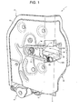
- Number 1 in Figures 1 to 4 indicates as a whole an electric latch for a vehicle door (not shown).
- Latch 1 comprises:
- striker 4 may be fixed to the vehicle door, and supporting body 2, together with latch 1, may be fixed to the doorpost.
- supporting body 2 integrally comprises two plates 8, 9 arranged perpendicularly to each other and extending from a common end edge to define a substantially L-shaped profile when viewed along a plane perpendicular to both plates 8, 9.
- plate 8 Starting from the common end edge, plate 8 has a bigger extent than plate 9.
- each plate 8, 9 is delimited by a first face 8a, 9a facing the other plate 9, 8, and by an opposite face 8b, 9b.
- Supporting body 2 has a peripheral edge 10 protruding from faces 8b, 9b of plates 8, 9 except from the portion which is in use positioned inferiorly ( Figure 1 ).
- a front cover 11 having a substantially L-shaped profile is normally fixed to supporting body 2 in a position, in which it extends parallel to faces 8b, 9b of both plates 8, 9 and cooperates peripherally with protruding edge 10.
- Supporting body 2 defines a C-shaped lateral opening 12 extending along both plates 8 and 9 from the common end edge and adapted to receive striker 4 when closing the door.
- opening 12 comprises a substantially quadrangular inlet portion 12a extending through plate 9, and a receiving portion 12b extending along plate 8 and closed on the opposite side to the inlet portion 12a ( Figures 1 and 2 ). As shown in Figures 3 and 4 , on face 8a of plate 8, opening 12 is covered by a casing 13 fixed to both plates 8, 9 and defining a seat for receiving striker 4.
- opening 12 and casing 13 are both arranged substantially on an intermediate portion of supporting body 2.
- cover 11 is provided with an opening 14 substantially having the same profile as opening 12 and substantially aligned therewith.
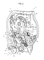
- closure assembly 3 and back-up mechanism 7 are both arranged on face 8b of plate 8 so being housed in the gap between supporting body 2 and cover 11, whilst release and lock assembly 6 and inside emergency release lever 5 are placed on face 8a of plate 8.
- closure assembly 3 basically comprises a ratchet 15 superimposed on the opening 12 for receiving striker 4, and a releasable locking mechanism 16 cooperating with ratchet 15 to prevent disengagement between the striker 4 and the ratchet 15.
- ratchet 15 is hinged about a fixed pin 17 extending orthogonally through plate 8, protruding from both faces 8a, 8b of the plate 8 and having an axis A. More specifically, ratchet 15 is defined by a contoured plate hinged at an intermediate portion about pin 17 and having a C-shaped peripheral seat 18 bounded laterally by two teeth 19, 20 and adapted to receive striker 4.
- Spring 21 has one end 21a cooperating with casing 13, and an opposite end 21b secured to ratchet 15.
- ratchet 15 When the door is slammed, ratchet 15 is rotated by striker 4 about axis A to lock or click onto locking assembly 16, as explained in detail below, in two different positions: a partially locked or first-click position (not shown), and a fully locked or second-click position ( Figures 1 , 2 and 6 ), in which striker 4 is locked inside seat 18 and prevented from withdrawing by tooth 19 increasingly closing off receiving portion 12b of opening 12. In the orientation of Figures 2 , 5 , 7 , 8 and 9 , the ratchet 15 will rotate anticlockwise to enter the release position.
- striker 4 in the fully locked position, striker 4 is securely ensconced in seat 18 of ratchet 15 such that the vehicle door is completely closed and door seals (not shown) are compressed. In the partially locked position, striker 4 is loosely secured in seat 18 of ratchet 15 such that the vehicle door is locked but not completely closed against its seals.
- the fully locked and partially locked positions are defined by locking mechanism 16 engaging respective shoulders 22, 23 (also visible in Figures 7 , 8 and 10 ) formed along the peripheral edge of ratchet 15, on the side delimiting tooth 20 on the opposite side to seat 18.
- locking mechanism 16 is arranged on one side of ratchet 15 and receiving portion 12b of opening 12; in the position in which latch 1 is fixed to the vehicle door ( Figures 1 and 2 ), locking mechanism 16 is arranged at a lower position than ratchet 15.
- locking mechanism 16 basically comprises:
- Primary pawl 25, auxiliary ratchet 26 and secondary pawl 27 are all defined by contoured plates substantially extending along the same plane as ratchet 15.
- Auxiliary ratchet 26 is hinged about a fixed pin 28 extending orthogonally through plate 8, protruding from both faces 8a, 8b of the plate 8 and having an axis B parallel to axis A.
- Primary pawl 25 is carried by auxiliary ratchet 26 in a rotating manner about an axis C parallel to axis B and spaced therefrom; in particular, primary pawl 25 is carried by auxiliary ratchet 26 on one side of pin 28 and is biased, in a known manner, to the ratchet checking position by a spring (known per se and not shown).
- Primary pawl 25 basically comprises a cylindrical stub 29 ( Figure 5 ) coaxial with axis C and pivotally mounted into a cylindrical bore (not visible) formed on a peripheral portion of auxiliary ratchet 26, and a check arm 30 extending radially from the stub 29 and adapted to pivot between the ratchet checking position, in which the check arm 30 stops the opening urge of the ratchet 15, as shown in Figure 2 , and the ratchet release position, in which the check arm 30 does not inhibit rotation of the ratchet 15 to its release position, as shown in Figures 7 and 9 .
- primary pawl 25 will rotate anticlockwise to move into the ratchet release position.
- check arm 30 of primary pawl 25 interacts in use with the shoulders 22, 23 of the ratchet 15 to define the fully locked position and the partially locked position, respectively.
- Auxiliary ratchet 26 can rotate about pin 28 between the enabling position, in which the auxiliary ratchet 26 abuts ratchet 15 through primary pawl 25, as shown in Figure 2 , and the disabling position, in which the auxiliary ratchet 26 maintains the primary pawl 25 disengaged from the ratchet 15, as shown in Figures 7 and 9 .
- auxiliary ratchet 26 will rotate anticlockwise to enter the disabling position.
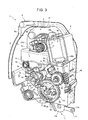
- Auxiliary ratchet 26 is further provided with a protruding stub 31 arranged on the opposite side of pin 28 with respect to primary pawl 25, extending parallel to pin 28 and engaging a through opening formed in plate 8; as visible in Figures 3 and 4 , stub 31 has a free end portion projecting from face 8a of plate 8 and adapted to receive actuating forces from release and lock assembly 6, as it will be explained in greater detail later on.
- auxiliary ratchet 26 integrally comprises a first upper portion 26a, located adjacent to ratchet 15 and which carries primary pawl 25, pin 28 and stub 31, and a second bottom portion 26b, located on the opposite part of portion 26a with respect to ratchet 15; second bottom portion 26b defines, at one side end, a tooth 36 adapted to cooperate in use with secondary pawl 27, and, at the opposite side end and in a position close to stub 31, a lateral edge 37 adapted to cooperate in use with back-up mechanism 7, as it will explained later on.
- a spring 38 ( Figure 2 ), wound about a fixed post extending parallel to pin 28 from face 8b of plate 8, biases auxiliary ratchet 26 to the disabling position.
- Spring 38 has one end 38a secured to plate 8, and an opposite end 38b cooperating with lateral edge 37 of auxiliary ratchet 26.
- secondary pawl 27 is arranged in a position facing the edge of auxiliary ratchet 26 provided with tooth 36 and is hinged about a fixed pin 40 extending orthogonally through plate 8, protruding from both faces 8a, 8b of the plate 8 and having an axis D parallel to axes A, B and C.
- pin 40 is arranged on the opposite side of primary pawl 25 with respect to pin 28.
- Secondary pawl 27 has an elongated configuration and has one upper portion 41 adjacent to ratchet 15 and hinged to pin 40, and one opposite free end portion 42 adjacent to the edge of supporting body 2 in use positioned inferiorly.
- Secondary pawl 27 has an intermediate protruding tooth 43 for engaging tooth 36 of auxiliary ratchet 26.
- Secondary pawl 27 is biased towards tooth 36 of auxiliary ratchet 26 by a spring 45 ( Figures 2 and 5 ) wound about pin 40 and having one tang (not visible) secured to the plate 8 and one opposite tang (also not visible) cooperating with the secondary pawl 27.
- spring 45 pushes secondary pawl 27 towards the auxiliary ratchet holding position.
- release and lock assembly 6 basically comprises an electric motor 46, a worm gear 48 coaxially coupled to a rotating member 49 of motor 46, a first gear wheel 50 meshing with worm gear 48, an actuating lever 51 adapted to interact with stub 31 of auxiliary ratchet 26, and a second gear wheel 52 meshing with gear wheel 50 and adapted to interact with secondary pawl 27 and with actuating lever 51.
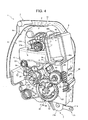
- electric motor 46 is fixed to the portion of plate 8 defining the upper part of such plate in the use position ( Figure 1 to 4 ). As visible in Figures 3 and 4 , in the use position, electric motor 46 has a bottom portion 46a positioned adjacent to, and facing, the closed side of opening 12 and casing 13, and an upper portion 46b extending superiorly with respect to the casing 13; worm gear 48, gear wheels 50, 52 and actuating lever 51 are all arranged inferiorly with respect to casing 13.
- electric motor 46 is arranged in a position adjacent to ratchet 15; in practice, the electric motor 46 and the ratchet 15 are arranged on the supporting body 2 substantially at the same height.
- Gear wheel 50 is mounted for rotation about fixed pin 40 of axis D, whilst gear wheel 52 is mounted for rotation about a post 56 having an axis F parallel to axes A, B, C, D and fixed orthogonally to face 8a of plate 8.
- Actuating lever 51 is hinged about fixed pin 28.
- Gear wheel 52 is functionally interposed between gear wheel 50 and actuating lever 51: this means that gear wheel 52 is driven by gear wheel 50 and drives actuating lever 51.
- gear wheel 52 comprises a discus 58 mounted for rotation about post 56, a plurality of teeth 59 extending along the periphery of the discus 58 and meshing with corresponding teeth of gear wheel 50, and first and second cam means 60, 61 provided on the opposite faces of discus 58 for interacting with secondary pawl 27 and actuating lever 51, respectively.
- first cam means 60 comprise a shaped push block 62, which is provided on the face of discus 58 facing face 8a of plate 8 and protrudes, through a relative opening of the plate 8, on the other side of the latter for interacting with secondary pawl 27 during an initial part of a release rotational movement (anticlockwise in the orientation of Figures 3 and 4 ) imparted to gear wheel 52 by electric motor 46.
- push block 62 is adapted to interact with an operative portion 64 ( Figure 5 ) of secondary pawl 27 arranged below tooth 43, i.e. between tooth 43 and face 8b of plate 8, in order to move the secondary pawl 27 to the auxiliary ratchet release position (clockwise about pin 40 in the orientation of Figures 1 , 2 and 5 ).
- second cam means 61 comprise two shaped push blocks 65, 66, which protrude in a direction parallel to axis F from the face of discus 58 opposite to the face carrying push block 62, are angularly spaced to one another about the axis F and are adapted to cooperate, along opposite directions, with an arm 67 of actuating lever 51.
- push blocks 65, 66 are substantially located at diametrically opposite positions on discus 50 and have different external configurations.
- push block 65 is adapted to interact with arm 67 of actuating lever 51 during an ending part of the release rotational movement (anticlockwise in the orientation of Figures 3 and 4 ) imparted to gear wheel 52 by electric motor 46.
- Push block 66 is instead adapted to interact with arm 67 of actuating lever 51 during a lock rotational movement (clockwise in the orientation of Figures 4 and 6 ) imparted to gear wheel 52 by electric motor 46 in a direction opposite to the direction of the release rotational movement.
- actuating lever 51 basically comprises the arm 67 and a fork portion 68 angularly spaced from the arm 67 about axis B and defining a seat for receiving the free end portion of stub 31 of auxiliary ratchet 26.
- fork portion 68 houses stub 31 with play in an angular direction about axis B.
- Fork portion 68 is delimited by two opposite push surfaces 69, 70 ( Figure 6 ) facing one another, arranged on opposite sides of stub 31 and adapted to exert respective pushing actions on the stub 31 during opposite rotational movements of actuating lever 51 about pin 28.
- actuating lever 51 is rotated along a first direction (clockwise in Figures 3 and 4 ) about axis B so producing interaction of push surface 69 with stub 31; the result is a rotation of auxiliary ratchet 26 into the disabling position. Due to the fact that auxiliary ratchet 26 is biased by spring 38 to the disabling position when secondary pawl 27 is moved to the auxiliary ratchet release position, the interaction between the push block 65 with the arm 67 only serves to force movement of auxiliary ratchet 26 into such disabling position in case the spring action were insufficient.
- actuating lever 51 is rotated along a second direction (anticlockwise in Figure 6 ) about axis B, opposite to the first direction, so producing interaction of push surface 70 with stub 31; the result is a rotation of auxiliary ratchet 26 into the enabling position.
- Actuating lever 51 is biased by a spring 53, wound about a fixed post parallel to pin 28, into a rest position, in which the actuating lever 51 cannot produce any movement of auxiliary ratchet 26.
- inside emergency release lever 5 is of the rocker-type and comprises an intermediate portion 5a hinged about fixed pin 28, and two arms 5b, 5c radially protruding from intermediate portion 5a and angularly spaced from one another about axis B.
- arm 5b extends with play through an opening 9c formed on plate 9 and has a free end externally protruding from the plate 9 and adapted to be connected to a manually-operated transmission device (known per se and not shown), for instance a tie-rod or a Bowden cable transmission, which can be activated by an inside control element (known per se and not shown) provided on the vehicle door.
- a manually-operated transmission device for instance a tie-rod or a Bowden cable transmission, which can be activated by an inside control element (known per se and not shown) provided on the vehicle door.
- Arm 5c has an end slot 5d, which is engaged by a stub 35 orthogonally protruding from a free end of check arm 30 of primary pawl 25 and extending with play through an opening formed on plate 8.
- a rotation can be impressed to inside emergency release lever 5 so that arm 5c can interact with stub 35 of primary pawl 25 for releasing the primary pawl 25 form ratchet 15 and allowing an emergency opening of the latch 1.
- the rotation impressed to inside emergency release lever 5 is in a clockwise direction.
- back-up mechanism 7 is substantially arranged on the opposite side of locking mechanism 16 with respect to ratchet 15; in the position in which latch 1 is fixed to the vehicle door ( Figures 1 and 2 ), back-up mechanism 7 is arranged at a lower position than locking mechanism 16.
- Back-up mechanism 7 comprises an outside emergency release lever 71, which can be manually operated from the outside of the vehicle for moving secondary pawl 27 into the auxiliary ratchet release position so permitting an emergency opening of latch 1, and an outside emergency lock lever 72, which can be manually operated from the outside of the vehicle for moving auxiliary ratchet 26 into its enabling position so permitting an emergency lock of the latch 1.
- Outside emergency release lever 71 is of the rocker-type and comprises an intermediate portion 71a hinged about a fixed pin (not shown) extending orthogonally from face 8b of plate 8 and having an axis H parallel to axes A to G.
- Outside emergency release lever 71 also comprises two arms 71b, 71c radially protruding from intermediate portion 71a and angularly spaced from one another about axis H.
- Arm 71b has a free end adapted to be connected to a manually-operated transmission device (known per se and not shown), for instance a tie-rod or a Bowden cable transmission, which can be activated by an outside control element (known per se and not shown), for instance an external key.
- a manually-operated transmission device for instance a tie-rod or a Bowden cable transmission
- an outside control element for instance an external key.
- the free end of arm 71b can receive opposite activation forces T1, T2 by the transmission device, resulting in opposite rotations of the outside emergency release lever 71 about axis H.
- a first activation force indicated by arrow T1 in Figures 1 to 4 and 7 to 10 , produces a rotational movement along a first direction S1 (anticlockwise in Figures 7 to 9 ) of outside emergency release lever 71; in a different manner, a second activation force T2, opposite to activation force T1, produces a rotational movement along a second direction S2 (clockwise in Figures 7 to 9 ) of outside emergency release lever 71, opposite to first direction S1.
- Arm 71c is provided with first transmission means 76 for interacting with free end portion 42 of secondary pawl 27 as a result of a rotation of outside emergency release lever 71 in direction S1 (or as a result of an action on outside emergency release lever 71 in direction T1), and with second transmission means 79 for interacting with outside emergency lock lever 72 as a result of a rotation of outside emergency release lever 71 in direction S2 (or as a result of an action on outside emergency release lever 71 in direction T2).
- first transmission means 76 are defined by an anvil-shaped end of arm 71c; when activation force T1 is applied to the free end of arm 71b, outside emergency release lever 71 rotates about axis H in direction S1 so causing interaction of anvil-shaped end of first transmission means 76 with free end portion 42 of secondary pawl 27 and rotation of the latter into the auxiliary ratchet release position.
- Outside emergency release lever 71 is biased by a spring 77, wound about the relative pin, into a rest position, in which the outside emergency release lever 71 cannot produce any movement of secondary pawl 27 or outside emergency lock lever 72.
- Spring 77 has a first tang 77a secured to the body of outside emergency release lever 71 and a second tang 77b extending along arm 71c ( Figure 10 ) and cooperating with a receiving portion 78 of outside emergency lock lever 72 to actuate the latter, as it will be explained in greater detail later on.
- tang 77b of spring 77 defines second transmission means 79.
- Outside emergency lock lever 72 is also of the rocker-type and comprises an intermediate portion 72a hinged about a fixed pin (not shown) extending orthogonally from face 8b of plate 8 and having an axis L parallel to axes A to H.
- Outside emergency lock lever 72 further comprises two arms 72b, 72c protruding from intermediate portion 72a and angularly spaced from one another about axis L.
- Arm 72b is positioned adjacent to arm 71c of outside emergency release lever 71 and has a laterally protruding stub defining the portion 78 cooperating with tang 77b of spring 77 of the outside emergency release lever 71.
- Arm 72c is positioned adjacent to auxiliary ratchet 26 and is adapted to interact with lateral edge 37 of the auxiliary ratchet 26 to move the latter into the enabling position as a result of a rotation of outside emergency lock lever 72 produced by applying activation force T2 on the free end of arm 71b of outside emergency release lever 71.
- Outside emergency lock lever 72 is biased by a spring (known per se and not shown) into a rest position, in which it is spaced from auxiliary ratchet 26.
- latch 1 advantageously comprises an inhibiting lever 81 which, upon movement of ratchet 15 towards the release position, is set to a disabling condition ( Figures 7 and 8 ), in which the inhibiting lever 81 prevents interaction of back-up mechanism 7 with auxiliary ratchet 26.
- inhibiting lever 81 is of the rocker-type and is interposed between ratchet 15 and outside emergency lock lever 72.
- Inhibiting lever 81 comprises an intermediate portion 81a hinged about pin 28, and two arms 81b, 81c protruding from intermediate portion 81a, angularly spaced from one another about axis B and adapted to interact in use with ratchet 15 and outside emergency lock lever 72, respectively.
- inhibiting lever 81 substantially extends along a plane parallel to, and interposed between, face 8b of plate 8 and the plane of ratchet 15 and auxiliary ratchet 26; in this way, auxiliary ratchet 26 is substantially superimposed over the most part of the body of inhibiting lever 81, and ratchet 15 is substantially superimposed over an end portion 82 of arm 81b.
- arm 81c has one end portion 83, which is adapted to be interposed between the lateral edge 37 of the auxiliary ratchet 26 and the arm 72c of outside emergency lock lever 72 when the inhibiting lever 81 is in the disabling condition.
- the end portion 82 of arm 81b is instead adapted to interact with a push block 84 protruding from tooth 20 of ratchet 15 towards face 8b of plate 8.
- Inhibiting lever 81 is biased by a spring 85 into an enabling position ( Figures 2 , 5 , 9 and 10 ), in which the inhibiting lever 81 has the arm 81c positioned out of the path followed by arm 72c of outside emergency lock lever 72 for acting on lateral edge 37 of auxiliary ratchet 26, and, upon movement of ratchet 15 towards the release position, is pushed to the disabling condition ( Figures 7 and 8 ), in which the inhibiting lever 81 maintains the end portion 83 interposed between the lateral edge 37 of the auxiliary ratchet 26 and the arm 72c of outside emergency lock lever 72 so preventing any action of the latter on the auxiliary ratchet 26.
- push block 84 of ratchet 15 is configured to start to interact with end portion 82 of arm 81b of inhibiting lever 81 before the ratchet 15 reaches the partially locked position during the opening of the latch 1 so that, in the partially locked position, the inhibiting lever 81 is already able to prevent any action of the outside emergency lock lever 72 on the auxiliary ratchet 26. More specifically, the push block 84 is configured to maintain the end portion 83 of inhibiting lever 81 in a position interposed between lateral edge 37 of auxiliary ratchet 26 and arm 72c of outside emergency lock lever 72, during the entire rotation of the ratchet 15 from the partially locked position to the release position.
- inhibiting lever 81 is set to a final disabling position shown in Figures 7 and 8 .
- Spring 85 is wound about a post (not shown) projecting orthogonally from face 8b of plate 8 in a lateral position with respect to arm 81b of inhibiting lever 81; spring 85 has a first tang 85a secured to plate 8 and a second tang 85b cooperating with arm 81b of inhibiting lever 81.
- the latch 1 is released by activating electric motor 46 so as to obtain anticlockwise rotation of gear wheel 52 about axis F (visible by comparing Figures 3 and 4 ).
- push block 65 of cam means 61 moves towards arm 67 of actuating lever 51 and push block 60 of cam means 60 ( Figure 5 ) interacts with operative portion 64 of secondary pawl 27 so moving the secondary pawl 27 into the auxiliary ratchet release position.
- auxiliary ratchet 26 Under the thrust of spring 38, auxiliary ratchet 26 is therefore free to rotate about axis B into its disabling position. Should the spring action be insufficient, the interaction of push block 65 of cam means 61 on arm 67 of actuating lever 51 produces the clockwise rotation of the actuating lever 51 about axis B with the consequent interaction of surface 69 of fork portion 68 on stub 31 of auxiliary ratchet 26.
- opening of the latch 1 may be performed by acting on inside emergency release lever 5 from the inside of the vehicle, for instance by manually operating an inside control element, or by acting on the outside emergency release lever 71 from the outside of the vehicle, for instance by an external key.
- auxiliary ratchet 26 Under the thrust of spring 38, auxiliary ratchet 26 is therefore free to rotate about axis B into its disabling position. This rotation produces a corresponding rotation of primary pawl 25 about axis C so as to free ratchet 15, which can rotate into the release position ( Figures 7 and 8 ) under the thrust of spring 21.
- ratchet 15 interacts with end portion 82 of inhibiting lever 81 through push block 84, so producing a rotation of the inhibiting lever 81 about axis B in opposition to spring 85 and towards the final disabling position ( Figures 7 and 8 ).
- the push block 84 of ratchet 15 starts to interact with end portion 82 of arm 81b of inhibiting lever 81 before the ratchet 15 reaches the partially locked position so that, in the partially locked position, the inhibiting lever 81 is already able to prevent any action of the outside emergency lock lever 72 on the auxiliary ratchet 26 (disabling condition).
- the push block 84 maintains the end portion 83 of inhibiting lever 81 in a position interposed between lateral edge 37 of auxiliary ratchet 26 and arm 72c of outside emergency lock lever 72.
- the final disabling position of the inhibiting lever 81 is reached when the ratchet 15 is in the release position.
- inhibiting lever 81 permits to avoid any undesired displacement of the auxiliary ratchet 26 in the disabling position when the door is open, which, upon a subsequent accidental closure of the door with the key inside the vehicle, could result in the impossibility to open again the door.
- the particular layout of the latch 1, with electric motor 46 placed on the upper portion of supporting body 2, permits to minimize the risks that damp possibly entering the latch 1 through opening 12 may spread to the electric motor 46.
Landscapes
- Lock And Its Accessories (AREA)
Claims (11)
- Serrure de véhicule (1) comprenant :- un cliquet (15) mobile entre une position de libération, dans laquelle le cliquet (15) est positionné de façon à recevoir ou libérer un percuteur (4), et au moins une position de verrouillage, dans laquelle le cliquet (15) est positionné de façon à maintenir ledit percuteur (4) ;- un doigt principal (25) mobile entre une position de contrôle de cliquet, dans laquelle le doigt principal (25) est positionné de façon à maintenir ledit cliquet (15) dans la position de verrouillage et une position de libération de cliquet, dans laquelle le doigt principal (25) permet le déplacement dudit cliquet (15) hors de ladite position de verrouillage ;- un cliquet auxiliaire (26) relié fonctionnellement audit doigt primaire (25) et mobile entre une position d'activation, dans laquelle le doigt primaire (25) est autorisé à se déplacer vers sa position de contrôle de cliquet, et une position de désactivation, dans laquelle le cliquet auxiliaire (26) positionne le doigt principal (25) dans sa position de libération de cliquet ;- un doigt secondaire (27) mobile entre une position de maintien de cliquet auxiliaire, dans laquelle le doigt secondaire (27) est positionné de façon à maintenir ledit cliquet auxiliaire (26) dans sa position d'activation, et une position de libération de cliquet auxiliaire, dans laquelle le doigt secondaire (27) est positionné de façon à permettre le déplacement dudit cliquet auxiliaire (26) dans sa position de désactivation ;- des moyens d'actionnement à commande électrique (6), qui peuvent être activés sélectivement de façon à déplacer ledit doigt secondaire (27) dans ladite position de libération de cliquet auxiliaire et ledit cliquet auxiliaire (26) dans ladite position d'activation, et- un mécanisme de sécurité (7 qui peut être actionné manuellement et sélectivement par l'utilisateur de façon à déplacer ledit doigt secondaire (27) dans ladite position de libération de cliquet auxiliaire ou de façon à déplacer ledit cliquet auxiliaire (26) dans ladite position d'activation ;la serrure de véhicule comprenant en outre un levier d'inhibition (81) qui, lors d'un déplacement dudit cliquet (15) dans ladite position de libération, est placé à un état de désactivation, dans laquelle le levier d'inhibition (81) empêche l'interaction dudit mécanisme de sécurité (7) avec ledit cliquet auxiliaire (26).
- Serrure selon la revendication 1, dans lequel ledit levier d'inhibition (81) est interposé entre ledit cliquet (15) et ledit mécanisme de sécurité (7).
- Serrure selon la revendication 1 ou 2, dans lequel ledit mécanisme de sécurité (7) peut être actionné manuellement par l'utilisateur dans une première direction (T1) de façon à interagir avec ledit doigt secondaire (27) et dans une seconde direction (T2), opposée à ladite première direction (T1), de façon à interagir avec ledit cliquet auxiliaire (26).
- Serrure selon l'une quelconque des revendications précédentes, dans lequel ledit cliquet (15) comprend des moyens de poussée (84) destinés à pousser ledit levier d'inhibition (81) dans ladite position de désactivation.
- Serrure selon la revendication 4, dans lequel ledit cliquet (15) peut également être placé dans une position partiellement verrouillée intermédiaire entre ladite position de libération et ladite position de verrouillage, et dans lequel ledit cliquet (15) et lesdits moyens de poussée (84) sont configurés de façon à interagir avec ledit levier d'inhibition (81) de telle manière que, en se déplaçant de ladite position partiellement verrouillée dans ladite position de libération, le cliquet (15) maintient le levier d'inhibition (81) dans ledit état de désactivation.
- Serrure selon l'une quelconque des revendications précédentes, dans lequel ledit levier d'inhibition (81) est poussé par des moyens élastiques (85) dans la position d'activation, dans laquelle le levier d'inhibition (81) ne peut pas interagir avec ledit mécanisme de sécurité (7).
- Serrure selon l'une quelconque des revendications précédentes, dans lequel ledit mécanisme de sécurité comprend un levier de libération d'urgence (71), qui peut être actionné par l'utilisateur de façon à déplacer ledit doigt secondaire (27) dans ladite position de libération de cliquet auxiliaire afin de permettre une ouverture d'urgence de la serrure (1), et un levier de verrouillage d'urgence (72), qui peut être actionné par l'utilisateur pour déplacer ledit cliquet auxiliaire (26) dans sa position d'activation permettant ainsi un verrouillage d'urgence de la serrure (1).
- Serrure selon la revendication 7, dans lequel ledit levier de libération d'urgence (71) est pourvu de premiers moyens de transmission (76) destinés à interagir avec ledit doigt secondaire (27) et de seconds moyens de transmission (79) destinés à interagir avec ledit levier de verrouillage d'urgence (72) et déplacer le levier de verrouillage d'urgence (72) vers ledit cliquet auxiliaire (26).
- Serrure selon la revendication 8, dans lequel lesdits seconds moyens de transmission (79) comprennent des moyens élastiques (77) supportés par ledit levier de libération d'urgence (71) et configurés pour coopérer directement avec ledit levier de verrouillage d'urgence (72).
- Serrure selon la revendication 8 ou 9, dans lequel ledit levier de libération d'urgence (71) peut être actionné manuellement par l'utilisateur dans lesdites première et seconde directions (T1, T2), dans lequel lesdits premiers moyens de transmission (76) coopèrent avec ledit doigt secondaire (27) à la suite d'une action sur le levier de libération d'urgence (71) dans ladite première direction (T1), et dans lequel lesdits seconds moyens de transmission (79) coopèrent avec le levier de verrouillage d'urgence (72) à la suite d'une action sur le levier de libération d'urgence (71) dans ladite seconde direction (T2).
- Serrure selon l'une quelconque des revendications précédentes, dans lequel ledit levier d'inhibition (81) comporte une portion intermédiaire (81a) articulée sur un axe fixe (28), un premier bras (81b) adapté pour recevoir une action de poussée de la part dudit cliquet (15) lorsque le cliquet (15) se déplace dans ladite position de libération, et un second bras (81c) comportant au moins une portion (83) adaptée pour être interposée entre ledit mécanisme de sécurité (7) et ledit cliquet auxiliaire (26) dans ledit état de désactivation du levier d'inhibition (81).
Priority Applications (6)
| Application Number | Priority Date | Filing Date | Title |
|---|---|---|---|
| EP14180972.3A EP2806091B1 (fr) | 2012-04-17 | 2012-04-17 | Serrure de véhicule électrique |
| EP20120164511 EP2653639B1 (fr) | 2012-04-17 | 2012-04-17 | Serrure de véhicule électrique |
| US13/864,603 US9476230B2 (en) | 2012-04-17 | 2013-04-17 | Electrical vehicle latch |
| CN201710089765.0A CN107035246B (zh) | 2012-04-17 | 2013-04-17 | 电动车辆闩锁 |
| CN201310161288.6A CN103375068B (zh) | 2012-04-17 | 2013-04-17 | 电动车辆闩锁 |
| US15/277,203 US20170067272A1 (en) | 2012-04-17 | 2016-09-27 | Electrical Vehicle Latch |
Applications Claiming Priority (1)
| Application Number | Priority Date | Filing Date | Title |
|---|---|---|---|
| EP20120164511 EP2653639B1 (fr) | 2012-04-17 | 2012-04-17 | Serrure de véhicule électrique |
Related Child Applications (2)
| Application Number | Title | Priority Date | Filing Date |
|---|---|---|---|
| EP14180972.3A Division EP2806091B1 (fr) | 2012-04-17 | 2012-04-17 | Serrure de véhicule électrique |
| EP14180972.3A Division-Into EP2806091B1 (fr) | 2012-04-17 | 2012-04-17 | Serrure de véhicule électrique |
Publications (2)
| Publication Number | Publication Date |
|---|---|
| EP2653639A1 EP2653639A1 (fr) | 2013-10-23 |
| EP2653639B1 true EP2653639B1 (fr) | 2014-09-24 |
Family
ID=45977268
Family Applications (2)
| Application Number | Title | Priority Date | Filing Date |
|---|---|---|---|
| EP20120164511 Active EP2653639B1 (fr) | 2012-04-17 | 2012-04-17 | Serrure de véhicule électrique |
| EP14180972.3A Active EP2806091B1 (fr) | 2012-04-17 | 2012-04-17 | Serrure de véhicule électrique |
Family Applications After (1)
| Application Number | Title | Priority Date | Filing Date |
|---|---|---|---|
| EP14180972.3A Active EP2806091B1 (fr) | 2012-04-17 | 2012-04-17 | Serrure de véhicule électrique |
Country Status (3)
| Country | Link |
|---|---|
| US (2) | US9476230B2 (fr) |
| EP (2) | EP2653639B1 (fr) |
| CN (2) | CN103375068B (fr) |
Families Citing this family (28)
| Publication number | Priority date | Publication date | Assignee | Title |
|---|---|---|---|---|
| CN103742006B (zh) * | 2014-01-21 | 2016-06-29 | 安徽江淮汽车股份有限公司 | 一种车门闭锁器 |
| CN104847191B (zh) * | 2014-02-15 | 2017-11-17 | 因特瓦产品有限责任公司 | 用于车辆锁闩的致动器和与该致动器连用的多功能齿条 |
| DE102015002053A1 (de) * | 2014-02-24 | 2015-08-27 | Magna Closures Inc. | Schloss für eine Tür eines Kraftfahrzeugs |
| US10370879B2 (en) * | 2014-04-25 | 2019-08-06 | Magna Closures Inc. | Door latch with fast unlock |
| DE112015002256A5 (de) * | 2014-05-12 | 2017-07-06 | Kiekert Aktiengesellschaft | Kraftfahrzeugschloss |
| JP6454908B2 (ja) * | 2014-07-18 | 2019-01-23 | 三井金属アクト株式会社 | 車両用ドアラッチ装置 |
| DE102014218860A1 (de) * | 2014-09-19 | 2016-03-24 | Ford Global Technologies, Llc | Schiebetür für Kraftfahrzeuge |
| EP3260635B1 (fr) * | 2015-02-17 | 2019-10-16 | Gecom Corporation | Appareil de verrouillage de portière d'automobile |
| CN105625835B (zh) * | 2016-03-03 | 2018-03-23 | 皓月汽车安全系统技术股份有限公司 | 一种汽车背门锁体 |
| CN105863408B (zh) * | 2016-06-07 | 2018-10-19 | 昆山麦格纳汽车系统有限公司 | 双棘爪汽车门锁机构 |
| IT201600085579A1 (it) * | 2016-08-17 | 2018-02-17 | Cebi Italy Spa | Serratura per portello di veicolo. |
| DE102016011162A1 (de) * | 2016-09-16 | 2018-03-22 | Magna BÖCO GmbH | Verriegelungsvorrichtung für eine Fahrzeugtür und Verfahren |
| US20180087294A1 (en) * | 2016-09-23 | 2018-03-29 | Inteva Products, Llc | Liftgate latch |
| US11072948B2 (en) | 2016-12-14 | 2021-07-27 | Magna Closures S.P.A. | Smart latch |
| US11421454B2 (en) * | 2017-06-07 | 2022-08-23 | Magna Closures Inc. | Closure latch assembly with latch mechanism and outside release mechanism having reset device |
| DE102017123262A1 (de) * | 2017-10-06 | 2019-04-11 | Kiekert Ag | Kraftfahrzeugtürschloss |
| US11377883B2 (en) * | 2017-11-30 | 2022-07-05 | Magna Closures Inc. | Latch assembly for motor vehicle closure system having power release mechanism with override/reset |
| US11414903B2 (en) * | 2018-03-01 | 2022-08-16 | Magna Closures Inc. | Power operated closure latch assembly with an inside/outside backup mechanism having integrated splitter box arrangement |
| DE102019110480A1 (de) * | 2018-04-24 | 2019-11-07 | Magna Closures Inc. | Remote-Doppelsperranordnung zur Verwendung mit einer Verschluss-Verriegelungsanordnung in einer Fahrzeugtür |
| DE102019134659A1 (de) * | 2018-12-18 | 2020-06-18 | Magna Closures Inc. | Intelligente verriegelungsvorrichtung mit doppelklinken-verriegelungsmechanismus mit flexibler verbindung zu einem lösemechanismus |
| US11339591B2 (en) * | 2019-02-12 | 2022-05-24 | GM Global Technology Operations LLC | Latch assembly having self re-latching feature |
| DE102019107229A1 (de) * | 2019-03-21 | 2020-09-24 | Kiekert Aktiengesellschaft | Türschloss insbesondere Kraftfahrzeugtürschloss |
| JP7283015B2 (ja) * | 2019-11-12 | 2023-05-30 | 三井金属アクト株式会社 | ドアラッチ装置 |
| WO2021108907A1 (fr) * | 2019-12-03 | 2021-06-10 | Magna Closures Inc. | Ensemble verrou de fermeture avec mécanisme à double loquet |
| DE102020134972A1 (de) * | 2020-01-07 | 2021-07-08 | Magna Closures Inc. | Verschluss-verriegelungsvorrichtung mit kraftbetätigtem verriegelungs-lösemechanismus mit elektromagnetischem aktuator |
| DE102020102073A1 (de) * | 2020-01-29 | 2021-07-29 | Kiekert Aktiengesellschaft | Elektrisch betätigbares Kraftfahrzeugschloss |
| CN113756665B (zh) * | 2020-06-02 | 2023-02-17 | 麦格纳覆盖件有限公司 | 闭合闩锁组件及对闭合闩锁组件的操作进行控制的方法 |
| TR202021105A1 (tr) * | 2020-12-21 | 2022-07-21 | Mesan Kilit Anonim Sirketi | Geliştirilmiş bir tetik tertibatı içeren kancalı elektronik kilit. |
Family Cites Families (39)
| Publication number | Priority date | Publication date | Assignee | Title |
|---|---|---|---|---|
| JPS59195973A (ja) * | 1983-04-21 | 1984-11-07 | 株式会社大井製作所 | 自動車用ドアロツク装置 |
| DE4042678C1 (de) * | 1990-07-25 | 1999-10-21 | Kiekert Ag | Kraftfahrzeug-Türverschluß mit Speichereinrichtung für eine Öffnungsbedienung |
| US5277461A (en) * | 1992-12-24 | 1994-01-11 | General Motors Corporation | Vehicle door latch |
| US5454608A (en) * | 1993-10-12 | 1995-10-03 | General Motors Corporation | Vehicle door latch |
| US5537848A (en) * | 1994-06-27 | 1996-07-23 | General Motors Corporation | Deadbolt locking system |
| US5667263A (en) * | 1994-09-01 | 1997-09-16 | Kiekert Aktiengesellshaft | Power-actuated motor-vehicle door latch |
| US5634677A (en) * | 1994-09-01 | 1997-06-03 | Kiekert Aktiengesellschaft | Power-locking motor-vehicle door latch |
| CN1058068C (zh) * | 1994-11-10 | 2000-11-01 | 三井金属矿业株式会社 | 车辆用门锁装置 |
| DE19501493B4 (de) * | 1995-01-19 | 2006-06-22 | Kiekert Ag | Kraftfahrzeugtürverschluß |
| US6102453A (en) * | 1997-02-04 | 2000-08-15 | Atoma International Corp. | Vehicle door locking system with separate power operated inner door and outer door locking mechanisms |
| JP3143600B2 (ja) * | 1997-05-15 | 2001-03-07 | 三井金属鉱業株式会社 | 車両の車内鍵忘れ防止装置 |
| JP3143601B2 (ja) * | 1997-05-16 | 2001-03-07 | 三井金属鉱業株式会社 | 車両の車内鍵忘れ防止装置 |
| GB2339593A (en) * | 1998-07-15 | 2000-02-02 | Meritor Light Vehicle Sys Ltd | Vehicle door latch with disengageable power release |
| DE10006118A1 (de) * | 2000-02-11 | 2001-08-23 | Bosch Gmbh Robert | Kraftfahrzeug-Türschloß und Verfahren zum Steuern desselben |
| US6459223B2 (en) * | 2000-05-03 | 2002-10-01 | Robert Bosch Gmbh | Motor vehicle door lock and process for its control |
| DE10105445B4 (de) * | 2000-10-13 | 2012-07-26 | Witte-Velbert Gmbh & Co. Kg | Drehfallenverschluss |
| US6511106B2 (en) * | 2000-12-14 | 2003-01-28 | Delphi Technologies, Inc. | Vehicle door latch with double lock |
| US6517128B2 (en) * | 2001-02-06 | 2003-02-11 | Delphi Technologies, Inc. | Vehicle door latch with power operated release mechanism |
| DE20104625U1 (de) * | 2001-03-17 | 2002-08-01 | Kiekert Ag | Kraftfahrzeugtürverschluss |
| US6494506B1 (en) * | 2001-03-30 | 2002-12-17 | Tri/Mark Corporation | Latch and actuator assembly with no-lock-out feature |
| US6719333B2 (en) * | 2001-04-25 | 2004-04-13 | Delphi Technologies, Inc. | Vehicle door latch with power operated release mechanism |
| EP1380715A1 (fr) * | 2002-07-12 | 2004-01-14 | SO.GE.MI.- S.p.A. | Serrure de sécurité pour capots ou portes de véhicule automobile |
| JP2004251106A (ja) * | 2003-01-30 | 2004-09-09 | Aisin Seiki Co Ltd | ドアロック装置 |
| KR20050032210A (ko) * | 2003-10-01 | 2005-04-07 | 기아자동차주식회사 | 차량용 도어 래치 구조 |
| US20050280265A1 (en) * | 2004-05-04 | 2005-12-22 | Vlad Iliescu | Locking device for locking a closure panel |
| FR2871830A1 (fr) * | 2004-06-18 | 2005-12-23 | Arvinmeritor Light Vehicle Sys | Serrure de vehicule automobile |
| US7837243B2 (en) * | 2005-02-14 | 2010-11-23 | Magna Closures Inc. | Locking assembly for rear door |
| EP2071106B1 (fr) * | 2007-12-14 | 2015-10-28 | Volvo Car Corporation | Dispositif de fixation à fermeture motorisée |
| EP2310601B1 (fr) * | 2008-05-26 | 2016-02-24 | Magna Closures SpA | Serrure de véhicule automobile avec cliquet double |
| US20100127511A1 (en) * | 2008-11-26 | 2010-05-27 | Francisco Javier Vasquez | Vehicle door latch having a power lock-unlock mechanism |
| US8544901B2 (en) * | 2009-03-12 | 2013-10-01 | Ford Global Technologies, Llc | Universal global latch system |
| GB2474846A (en) * | 2009-10-27 | 2011-05-04 | Arvinmeritor Light Vehicle Sys | Latch system comprising key barrel operably coupled to latch via a clutch mechanism |
| JP4963720B2 (ja) * | 2009-12-21 | 2012-06-27 | 三井金属アクト株式会社 | 車両用ドアラッチ装置におけるアクチュエータ |
| JP5723388B2 (ja) * | 2010-02-05 | 2015-05-27 | マグナ クロージャーズ ソシエタ ペル アチオニ | 二重爪構造を備えた車両用ラッチ |
| DE112012002272T5 (de) * | 2011-05-27 | 2014-03-13 | Magna Closures S.P.A. | Doppeldrehfallen- und Doppelsperrklinken-Fahrzeugschloss mit Rückstell-Sanftauslauf |
| DE102012025009A1 (de) * | 2011-12-23 | 2013-06-27 | Magna Closures S.P.A. | System zum Feststellen des Betriebszustands eines Schlosses für eine Tür eines Kraftfahrzeugs und Verfahren zum Zusammensetzen dieses Systems |
| WO2013102838A1 (fr) * | 2012-01-03 | 2013-07-11 | Magna Closures S.P.A. | Ensemble de verrou de porte de véhicule |
| DE102015000824A1 (de) * | 2014-01-23 | 2015-07-23 | Magna Closures Inc. | Türschlossvorrichtung für Kraftfahrzeuge |
| US10392838B2 (en) * | 2015-06-11 | 2019-08-27 | Magna Closures Inc. | Key cylinder release mechanism for vehicle closure latches, latch assembly therewith and method of mechanically releasing a vehicle closure latch |
-
2012
- 2012-04-17 EP EP20120164511 patent/EP2653639B1/fr active Active
- 2012-04-17 EP EP14180972.3A patent/EP2806091B1/fr active Active
-
2013
- 2013-04-17 CN CN201310161288.6A patent/CN103375068B/zh active Active
- 2013-04-17 CN CN201710089765.0A patent/CN107035246B/zh active Active
- 2013-04-17 US US13/864,603 patent/US9476230B2/en active Active
-
2016
- 2016-09-27 US US15/277,203 patent/US20170067272A1/en not_active Abandoned
Also Published As
| Publication number | Publication date |
|---|---|
| CN107035246B (zh) | 2019-07-12 |
| US20130300133A1 (en) | 2013-11-14 |
| EP2806091A2 (fr) | 2014-11-26 |
| CN103375068A (zh) | 2013-10-30 |
| CN103375068B (zh) | 2017-04-12 |
| EP2806091A3 (fr) | 2015-12-16 |
| EP2653639A1 (fr) | 2013-10-23 |
| EP2806091B1 (fr) | 2017-10-04 |
| CN107035246A (zh) | 2017-08-11 |
| US9476230B2 (en) | 2016-10-25 |
| US20170067272A1 (en) | 2017-03-09 |
Similar Documents
| Publication | Publication Date | Title |
|---|---|---|
| EP2653639B1 (fr) | Serrure de véhicule électrique | |
| US10329807B2 (en) | Electrical vehicle latch | |
| JP5723388B2 (ja) | 二重爪構造を備えた車両用ラッチ | |
| US8596696B2 (en) | Vehicular latch with single notch ratchet | |
| US8596694B2 (en) | Vehicle latch with secondary engagement between cam and auxiliary pawl | |
| EP1953317B1 (fr) | Un véhicule à moteur avec un ensemble de loquet double | |
| KR101572247B1 (ko) | 차량 도어 록킹 장치 | |
| CN108999500B (zh) | 具闩锁机构和带重置装置的外侧释放机构的闭合闩锁组件 | |
| JP6163673B2 (ja) | フラップまたはドア用のロック | |
| KR102165338B1 (ko) | 플랩 또는 도어용 록 | |
| EP3140479B1 (fr) | Mécanismes de fermeture et de verrouillage | |
| KR20150053957A (ko) | 차량 도어 록 | |
| CA2896384A1 (fr) | Mecanisme de fermeture de porte de vehicule | |
| EP1176273B1 (fr) | Dispositif de verrouillage | |
| US11377882B2 (en) | Motor vehicle lock | |
| CN220705441U (zh) | 一种车门锁及车辆 | |
| JPS6242112B2 (fr) | ||
| CN114867927A (zh) | 具有双掣爪机构的闭合闩锁组件 |
Legal Events
| Date | Code | Title | Description |
|---|---|---|---|
| PUAI | Public reference made under article 153(3) epc to a published international application that has entered the european phase |
Free format text: ORIGINAL CODE: 0009012 |
|
| 17P | Request for examination filed |
Effective date: 20130417 |
|
| AK | Designated contracting states |
Kind code of ref document: A1 Designated state(s): AL AT BE BG CH CY CZ DE DK EE ES FI FR GB GR HR HU IE IS IT LI LT LU LV MC MK MT NL NO PL PT RO RS SE SI SK SM TR |
|
| AX | Request for extension of the european patent |
Extension state: BA ME |
|
| RAP1 | Party data changed (applicant data changed or rights of an application transferred) |
Owner name: MAGNA CLOSURES SPA |
|
| RIN1 | Information on inventor provided before grant (corrected) |
Inventor name: MARGHERITTI, ENRICO |
|
| REG | Reference to a national code |
Ref country code: DE Ref legal event code: R079 Ref document number: 602012003170 Country of ref document: DE Free format text: PREVIOUS MAIN CLASS: E05B0065320000 Ipc: E05B0081140000 |
|
| GRAP | Despatch of communication of intention to grant a patent |
Free format text: ORIGINAL CODE: EPIDOSNIGR1 |
|
| RIC1 | Information provided on ipc code assigned before grant |
Ipc: E05B 81/14 20140101AFI20140325BHEP Ipc: E05B 81/06 20140101ALN20140325BHEP Ipc: E05B 81/90 20140101ALI20140325BHEP |
|
| INTG | Intention to grant announced |
Effective date: 20140410 |
|
| GRAS | Grant fee paid |
Free format text: ORIGINAL CODE: EPIDOSNIGR3 |
|
| GRAA | (expected) grant |
Free format text: ORIGINAL CODE: 0009210 |
|
| AK | Designated contracting states |
Kind code of ref document: B1 Designated state(s): AL AT BE BG CH CY CZ DE DK EE ES FI FR GB GR HR HU IE IS IT LI LT LU LV MC MK MT NL NO PL PT RO RS SE SI SK SM TR |
|
| REG | Reference to a national code |
Ref country code: GB Ref legal event code: FG4D |
|
| REG | Reference to a national code |
Ref country code: CH Ref legal event code: EP |
|
| REG | Reference to a national code |
Ref country code: AT Ref legal event code: REF Ref document number: 688734 Country of ref document: AT Kind code of ref document: T Effective date: 20141015 |
|
| REG | Reference to a national code |
Ref country code: IE Ref legal event code: FG4D |
|
| REG | Reference to a national code |
Ref country code: DE Ref legal event code: R096 Ref document number: 602012003170 Country of ref document: DE Effective date: 20141106 |
|
| PG25 | Lapsed in a contracting state [announced via postgrant information from national office to epo] |
Ref country code: GR Free format text: LAPSE BECAUSE OF FAILURE TO SUBMIT A TRANSLATION OF THE DESCRIPTION OR TO PAY THE FEE WITHIN THE PRESCRIBED TIME-LIMIT Effective date: 20141225 Ref country code: FI Free format text: LAPSE BECAUSE OF FAILURE TO SUBMIT A TRANSLATION OF THE DESCRIPTION OR TO PAY THE FEE WITHIN THE PRESCRIBED TIME-LIMIT Effective date: 20140924 Ref country code: NO Free format text: LAPSE BECAUSE OF FAILURE TO SUBMIT A TRANSLATION OF THE DESCRIPTION OR TO PAY THE FEE WITHIN THE PRESCRIBED TIME-LIMIT Effective date: 20141224 Ref country code: SE Free format text: LAPSE BECAUSE OF FAILURE TO SUBMIT A TRANSLATION OF THE DESCRIPTION OR TO PAY THE FEE WITHIN THE PRESCRIBED TIME-LIMIT Effective date: 20140924 Ref country code: LT Free format text: LAPSE BECAUSE OF FAILURE TO SUBMIT A TRANSLATION OF THE DESCRIPTION OR TO PAY THE FEE WITHIN THE PRESCRIBED TIME-LIMIT Effective date: 20140924 |
|
| REG | Reference to a national code |
Ref country code: LT Ref legal event code: MG4D Ref country code: NL Ref legal event code: VDEP Effective date: 20140924 |
|
| PG25 | Lapsed in a contracting state [announced via postgrant information from national office to epo] |
Ref country code: LV Free format text: LAPSE BECAUSE OF FAILURE TO SUBMIT A TRANSLATION OF THE DESCRIPTION OR TO PAY THE FEE WITHIN THE PRESCRIBED TIME-LIMIT Effective date: 20140924 Ref country code: RS Free format text: LAPSE BECAUSE OF FAILURE TO SUBMIT A TRANSLATION OF THE DESCRIPTION OR TO PAY THE FEE WITHIN THE PRESCRIBED TIME-LIMIT Effective date: 20140924 Ref country code: HR Free format text: LAPSE BECAUSE OF FAILURE TO SUBMIT A TRANSLATION OF THE DESCRIPTION OR TO PAY THE FEE WITHIN THE PRESCRIBED TIME-LIMIT Effective date: 20140924 Ref country code: CY Free format text: LAPSE BECAUSE OF FAILURE TO SUBMIT A TRANSLATION OF THE DESCRIPTION OR TO PAY THE FEE WITHIN THE PRESCRIBED TIME-LIMIT Effective date: 20140924 |
|
| REG | Reference to a national code |
Ref country code: AT Ref legal event code: MK05 Ref document number: 688734 Country of ref document: AT Kind code of ref document: T Effective date: 20140924 |
|
| PG25 | Lapsed in a contracting state [announced via postgrant information from national office to epo] |
Ref country code: NL Free format text: LAPSE BECAUSE OF FAILURE TO SUBMIT A TRANSLATION OF THE DESCRIPTION OR TO PAY THE FEE WITHIN THE PRESCRIBED TIME-LIMIT Effective date: 20140924 |
|
| PG25 | Lapsed in a contracting state [announced via postgrant information from national office to epo] |
Ref country code: RO Free format text: LAPSE BECAUSE OF FAILURE TO SUBMIT A TRANSLATION OF THE DESCRIPTION OR TO PAY THE FEE WITHIN THE PRESCRIBED TIME-LIMIT Effective date: 20140924 Ref country code: SK Free format text: LAPSE BECAUSE OF FAILURE TO SUBMIT A TRANSLATION OF THE DESCRIPTION OR TO PAY THE FEE WITHIN THE PRESCRIBED TIME-LIMIT Effective date: 20140924 Ref country code: PT Free format text: LAPSE BECAUSE OF FAILURE TO SUBMIT A TRANSLATION OF THE DESCRIPTION OR TO PAY THE FEE WITHIN THE PRESCRIBED TIME-LIMIT Effective date: 20150126 Ref country code: EE Free format text: LAPSE BECAUSE OF FAILURE TO SUBMIT A TRANSLATION OF THE DESCRIPTION OR TO PAY THE FEE WITHIN THE PRESCRIBED TIME-LIMIT Effective date: 20140924 Ref country code: IS Free format text: LAPSE BECAUSE OF FAILURE TO SUBMIT A TRANSLATION OF THE DESCRIPTION OR TO PAY THE FEE WITHIN THE PRESCRIBED TIME-LIMIT Effective date: 20150124 Ref country code: ES Free format text: LAPSE BECAUSE OF FAILURE TO SUBMIT A TRANSLATION OF THE DESCRIPTION OR TO PAY THE FEE WITHIN THE PRESCRIBED TIME-LIMIT Effective date: 20140924 Ref country code: CZ Free format text: LAPSE BECAUSE OF FAILURE TO SUBMIT A TRANSLATION OF THE DESCRIPTION OR TO PAY THE FEE WITHIN THE PRESCRIBED TIME-LIMIT Effective date: 20140924 |
|
| PG25 | Lapsed in a contracting state [announced via postgrant information from national office to epo] |
Ref country code: PL Free format text: LAPSE BECAUSE OF FAILURE TO SUBMIT A TRANSLATION OF THE DESCRIPTION OR TO PAY THE FEE WITHIN THE PRESCRIBED TIME-LIMIT Effective date: 20140924 Ref country code: AT Free format text: LAPSE BECAUSE OF FAILURE TO SUBMIT A TRANSLATION OF THE DESCRIPTION OR TO PAY THE FEE WITHIN THE PRESCRIBED TIME-LIMIT Effective date: 20140924 |
|
| REG | Reference to a national code |
Ref country code: DE Ref legal event code: R097 Ref document number: 602012003170 Country of ref document: DE |
|
| PG25 | Lapsed in a contracting state [announced via postgrant information from national office to epo] |
Ref country code: DK Free format text: LAPSE BECAUSE OF FAILURE TO SUBMIT A TRANSLATION OF THE DESCRIPTION OR TO PAY THE FEE WITHIN THE PRESCRIBED TIME-LIMIT Effective date: 20140924 |
|
| PLBE | No opposition filed within time limit |
Free format text: ORIGINAL CODE: 0009261 |
|
| STAA | Information on the status of an ep patent application or granted ep patent |
Free format text: STATUS: NO OPPOSITION FILED WITHIN TIME LIMIT |
|
| 26N | No opposition filed |
Effective date: 20150625 |
|
| PG25 | Lapsed in a contracting state [announced via postgrant information from national office to epo] |
Ref country code: MC Free format text: LAPSE BECAUSE OF FAILURE TO SUBMIT A TRANSLATION OF THE DESCRIPTION OR TO PAY THE FEE WITHIN THE PRESCRIBED TIME-LIMIT Effective date: 20140924 Ref country code: LU Free format text: LAPSE BECAUSE OF FAILURE TO SUBMIT A TRANSLATION OF THE DESCRIPTION OR TO PAY THE FEE WITHIN THE PRESCRIBED TIME-LIMIT Effective date: 20150417 |
|
| REG | Reference to a national code |
Ref country code: CH Ref legal event code: PL |
|
| REG | Reference to a national code |
Ref country code: IE Ref legal event code: MM4A |
|
| PG25 | Lapsed in a contracting state [announced via postgrant information from national office to epo] |
Ref country code: LI Free format text: LAPSE BECAUSE OF NON-PAYMENT OF DUE FEES Effective date: 20150430 Ref country code: CH Free format text: LAPSE BECAUSE OF NON-PAYMENT OF DUE FEES Effective date: 20150430 |
|
| REG | Reference to a national code |
Ref country code: FR Ref legal event code: ST Effective date: 20151231 |
|
| PG25 | Lapsed in a contracting state [announced via postgrant information from national office to epo] |
Ref country code: SI Free format text: LAPSE BECAUSE OF FAILURE TO SUBMIT A TRANSLATION OF THE DESCRIPTION OR TO PAY THE FEE WITHIN THE PRESCRIBED TIME-LIMIT Effective date: 20140924 Ref country code: FR Free format text: LAPSE BECAUSE OF NON-PAYMENT OF DUE FEES Effective date: 20150430 |
|
| PG25 | Lapsed in a contracting state [announced via postgrant information from national office to epo] |
Ref country code: IE Free format text: LAPSE BECAUSE OF NON-PAYMENT OF DUE FEES Effective date: 20150417 |
|
| GBPC | Gb: european patent ceased through non-payment of renewal fee |
Effective date: 20160417 |
|
| PG25 | Lapsed in a contracting state [announced via postgrant information from national office to epo] |
Ref country code: MT Free format text: LAPSE BECAUSE OF FAILURE TO SUBMIT A TRANSLATION OF THE DESCRIPTION OR TO PAY THE FEE WITHIN THE PRESCRIBED TIME-LIMIT Effective date: 20140924 |
|
| PG25 | Lapsed in a contracting state [announced via postgrant information from national office to epo] |
Ref country code: GB Free format text: LAPSE BECAUSE OF NON-PAYMENT OF DUE FEES Effective date: 20160417 |
|
| PG25 | Lapsed in a contracting state [announced via postgrant information from national office to epo] |
Ref country code: SM Free format text: LAPSE BECAUSE OF FAILURE TO SUBMIT A TRANSLATION OF THE DESCRIPTION OR TO PAY THE FEE WITHIN THE PRESCRIBED TIME-LIMIT Effective date: 20140924 Ref country code: BG Free format text: LAPSE BECAUSE OF FAILURE TO SUBMIT A TRANSLATION OF THE DESCRIPTION OR TO PAY THE FEE WITHIN THE PRESCRIBED TIME-LIMIT Effective date: 20140924 Ref country code: HU Free format text: LAPSE BECAUSE OF FAILURE TO SUBMIT A TRANSLATION OF THE DESCRIPTION OR TO PAY THE FEE WITHIN THE PRESCRIBED TIME-LIMIT; INVALID AB INITIO Effective date: 20120417 |
|
| PG25 | Lapsed in a contracting state [announced via postgrant information from national office to epo] |
Ref country code: TR Free format text: LAPSE BECAUSE OF FAILURE TO SUBMIT A TRANSLATION OF THE DESCRIPTION OR TO PAY THE FEE WITHIN THE PRESCRIBED TIME-LIMIT Effective date: 20140924 |
|
| PGFP | Annual fee paid to national office [announced via postgrant information from national office to epo] |
Ref country code: IT Payment date: 20170420 Year of fee payment: 6 |
|
| PG25 | Lapsed in a contracting state [announced via postgrant information from national office to epo] |
Ref country code: BE Free format text: LAPSE BECAUSE OF FAILURE TO SUBMIT A TRANSLATION OF THE DESCRIPTION OR TO PAY THE FEE WITHIN THE PRESCRIBED TIME-LIMIT Effective date: 20140924 |
|
| PG25 | Lapsed in a contracting state [announced via postgrant information from national office to epo] |
Ref country code: MK Free format text: LAPSE BECAUSE OF FAILURE TO SUBMIT A TRANSLATION OF THE DESCRIPTION OR TO PAY THE FEE WITHIN THE PRESCRIBED TIME-LIMIT Effective date: 20140924 |
|
| PG25 | Lapsed in a contracting state [announced via postgrant information from national office to epo] |
Ref country code: AL Free format text: LAPSE BECAUSE OF FAILURE TO SUBMIT A TRANSLATION OF THE DESCRIPTION OR TO PAY THE FEE WITHIN THE PRESCRIBED TIME-LIMIT Effective date: 20140924 |
|
| PG25 | Lapsed in a contracting state [announced via postgrant information from national office to epo] |
Ref country code: IT Free format text: LAPSE BECAUSE OF NON-PAYMENT OF DUE FEES Effective date: 20180417 |
|
| PGFP | Annual fee paid to national office [announced via postgrant information from national office to epo] |
Ref country code: DE Payment date: 20230228 Year of fee payment: 12 |