EP2647539B1 - Klimaanlage für ein fahrzeug - Google Patents
Klimaanlage für ein fahrzeug Download PDFInfo
- Publication number
- EP2647539B1 EP2647539B1 EP10860135.2A EP10860135A EP2647539B1 EP 2647539 B1 EP2647539 B1 EP 2647539B1 EP 10860135 A EP10860135 A EP 10860135A EP 2647539 B1 EP2647539 B1 EP 2647539B1
- Authority
- EP
- European Patent Office
- Prior art keywords
- side plate
- vehicle
- air
- support
- conditioning apparatus
- Prior art date
- Legal status (The legal status is an assumption and is not a legal conclusion. Google has not performed a legal analysis and makes no representation as to the accuracy of the status listed.)
- Not-in-force
Links
Images



Classifications
-
- B—PERFORMING OPERATIONS; TRANSPORTING
- B60—VEHICLES IN GENERAL
- B60H—ARRANGEMENTS OF HEATING, COOLING, VENTILATING OR OTHER AIR-TREATING DEVICES SPECIALLY ADAPTED FOR PASSENGER OR GOODS SPACES OF VEHICLES
- B60H1/00—Heating, cooling or ventilating devices
-
- B—PERFORMING OPERATIONS; TRANSPORTING
- B60—VEHICLES IN GENERAL
- B60H—ARRANGEMENTS OF HEATING, COOLING, VENTILATING OR OTHER AIR-TREATING DEVICES SPECIALLY ADAPTED FOR PASSENGER OR GOODS SPACES OF VEHICLES
- B60H1/00—Heating, cooling or ventilating devices
- B60H1/00507—Details, e.g. mounting arrangements, desaeration devices
- B60H1/00514—Details of air conditioning housings
- B60H1/00535—Mounting or fastening of the housing to the vehicle
-
- B—PERFORMING OPERATIONS; TRANSPORTING
- B60—VEHICLES IN GENERAL
- B60H—ARRANGEMENTS OF HEATING, COOLING, VENTILATING OR OTHER AIR-TREATING DEVICES SPECIALLY ADAPTED FOR PASSENGER OR GOODS SPACES OF VEHICLES
- B60H1/00—Heating, cooling or ventilating devices
- B60H1/00357—Air-conditioning arrangements specially adapted for particular vehicles
- B60H1/00371—Air-conditioning arrangements specially adapted for particular vehicles for vehicles carrying large numbers of passengers, e.g. buses
-
- B—PERFORMING OPERATIONS; TRANSPORTING
- B61—RAILWAYS
- B61D—BODY DETAILS OR KINDS OF RAILWAY VEHICLES
- B61D27/00—Heating, cooling, ventilating, or air-conditioning
Definitions
- the present invention relates to an air-conditioning apparatus for a vehicle which is installed in a railroad vehicle.
- side plates of a main frame serving as a portion of a casing of an air-conditioning apparatus for a vehicle, include many parts, such as a bent member and a reinforcement, joined by welding.
- Each side plate includes two segments for an indoor chamber and an outdoor chamber and the segments are joined to each other after assembly of the chambers.
- the side plate is provided with many parts, for example, an attachment member used to attach the air-conditioning apparatus for a vehicle to a railroad vehicle, a hanging fitting used to hang the air-conditioning apparatus for a vehicle, a cover attachment fitting used to attach a cover to the main frame, and a reinforcing member for enhancing the strength of the side plate in order to prevent deformation after attachment to the railroad vehicle or upon hanging, the parts being attached to the side plate by welding (refer to Patent Literature 1, for example).
- Document US 2006/0059932 A1 discloses an air conditioning apparatus according to the preamble of claim 1.
- a further air conditioning apparatus is disclosed in Japanese Unexamined Patent Application Publication JP-A-59-223 558 (pages 2 to 3, FIGs. 3 and 8 ).
- a first object of the present invention is to provide an air-conditioning apparatus for a vehicle with a main frame capable of being assembled without increasing the number of parts or the number of processes.
- a second object of the present invention is to provide an air-conditioning apparatus for a vehicle in which an attachment member and a hanging fitting can be easily attached to each side plate of a main frame of the air-conditioning apparatus for a vehicle.
- the present invention provides an air-conditioning apparatus for a vehicle comprising a casing divided into an indoor chamber and an outdoor chamber by a partition plate, the casing including a cover placed on a top thereof; and- a refrigeration cycle device placed across the indoor chamber and the outdoor chamber in the casing, wherein the casing includes side plates, each side plate having a support on an outer surface thereof, the support having a curtain rail structure and configured for attachment to the vehicle, wherein each side plate including the support is extruded in one piece of metal.
- the side plate constituting the casing is extruded in one piece of metal, the number of parts and the number of processes can be reduced as compared with the above-described related art. Furthermore, since the side plate is a single part, the workability and quality of the side plate can be improved as compared with a side plate assembled from parts joined together, so that the cost can be reduced.
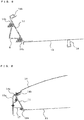
- FIG. 1 is a top view of an air-conditioning apparatus for a vehicle according to an exemplary Embodiment 1.
- FIG. 2 is a cross-sectional view illustrating the air-conditioning apparatus for a vehicle according to Embodiment 1 when viewed in a longitudinal direction thereof.
- the air-conditioning apparatus for a vehicle according to Embodiment 1 includes a main frame 1 and a cover 15, which constitute a casing, and further includes a refrigeration cycle device placed within the main frame 1, and is of a roof mounted type which is mounted on a roof 9 of a railroad vehicle.
- a gasket 10 (refer to FIG. 2 ) for sealing to protect a compartment of the railroad vehicle against water from outdoors is attached to the roof 9 of the railroad vehicle on which this type of air-conditioning apparatus for a vehicle is mounted.
- the gasket 10 is pressed by a bottom plate 13, which will be described later, when the air-conditioning apparatus for a vehicle is mounted on the roof 9 of the railroad vehicle.
- the above-described refrigeration cycle device includes a compressor 2, a refrigerant gas-liquid separator 3, an indoor heat exchanger 4, an outdoor heat exchanger 5, an indoor fan 6, and an outdoor fan 7.
- the indoor heat exchanger 4 and the indoor fan 6 of these components are arranged in an indoor chamber.
- the compressor 2, the refrigerant gas-liquid separator 3, the outdoor heat exchanger 5, and the outdoor fan 7 are arranged in an outdoor chamber.
- the above-described main frame 1 includes the bottom plate 13 which has a rectangular outside shape, end plates 11 which upwardly extend from both ends in a longitudinal direction of the bottom plate 13, side plates 14 arranged at both ends in a width direction of the bottom plate 13, and a partition plate 12 for separating the indoor chamber from the outdoor chamber.
- the cover 15, which is used to cover an upper opening of the main frame 1, is provided with side surface covers 15a attached to both ends thereof.
- the cover 15 and the side surface covers 15a comprise a material, such as FRP, stainless steel, or aluminum.
- the side plates 14 are arranged as both side surfaces of the indoor chamber and the outdoor chamber separated by the partition plate 12.
- Each side plate 14 is extruded in one piece of aluminum.
- the extruded one-piece side plate 14 includes a laterally extending part joined to the bottom plate 13, a side wall part bent upwardly from the laterally extending part, an inclined part bent so as to extend obliquely upwardly from the side wall part at a certain level to a side on which the laterally extending part extends, and an engagement part for the cover 15, the engagement part being bent upwardly at a right angle from the distal end of the inclined part.
- An attachment member 8 for attachment to the roof 9 of the railroad vehicle, a cover attachment fitting for attachment of the cover 15, and a hanging fitting for hanging the apparatus are attached to an outer surface of each side plate 14 by welding, the fittings being not illustrated.
- the parts comprise a material different from that of the side plate 14, such as stainless steel, the parts are attached to the side plate 14 with rivets or the like.
- each of the side plates 14 arranged as the side surfaces of the indoor chamber and the outdoor chamber is an extruded one-piece aluminum part, the number of parts and the number of processes are reduced as compared with those in the above-described related art. Furthermore, since each side plate 14 is a single part, the workability and quality of the side plate 14 are improved as compared with a side plate assembled from parts joined together, so that the cost can be reduced.
- FIG. 3 is a perspective view illustrating a main frame of an air-conditioning apparatus for a vehicle according to Embodiment 2 according to the invention.
- FIG. 4 illustrates enlarged cross-sections of a side plate of the main frame illustrated in FIG. 3 .
- FIG. 5 is a sectional view illustrating the side plate of FIG. 4 with an attachment member.
- FIG. 6 is a sectional view illustrating the side plate of FIG. 4 with a cover attachment fitting.
- the same components as or components equivalent to those in Embodiment 1 are designated by the same reference numerals.
- the air-conditioning apparatus for a vehicle according to Embodiment 2 is of the roof mounted type which is mounted on a roof 9 of a railroad vehicle, like the apparatus according to Embodiment 1.
- the air-conditioning apparatus includes a main frame 1 including side plates 14, which are arranged as both side surfaces of an indoor chamber and an outdoor chamber in the same way as the above description, each side plate 14 being extruded in one piece of aluminum.
- an indoor chamber portion of each side plate 14 includes a laterally extending part to be joined to a bottom plate 13, a side wall part bent obliquely upwardly from the laterally extending part so as to extend outwardly, an inclined part bent at a substantially right angle from the side wall part at a certain level so as to extend obliquely to a side on which the laterally extending part extends, an engagement part for a cover 15, the engagement part being bent upwardly at a right angle from the distal end of the inclined part.
- Two supports 14a are arranged so as to protrude from an outer surface of the side wall part of the side plate 14, each support 14a having a curtain rail structure and substantially the same length as a longitudinal length of the side plate 14, and one support 14b is disposed so as to protrude from an upper surface of the inclined part of the side plate 14, the support 14b having a curtain rail structure and the same length as that of the supports 14a.
- the above-described two supports 14a are molded such that the supports 14a and the side wall part have a substantially C-shaped cross-section.
- the one support 14b is also molded such that the support 14b and the inclined part have a substantially C-shaped cross-section in the same way as the above description.
- a gasket 10 for sealing to protect a compartment of the railroad vehicle against water from outdoors is attached to an edge of the above-described engagement part.
- an outdoor chamber portion of each side plate 14 of the side plates 14 includes a laterally extending part to be joined to the bottom plate 13, a side wall part bent obliquely upwardly from the laterally extending part so as to extend outwardly, an inclined part bent at a substantially right angle from the side wall part at the same level as the above-described level so as to extend obliquely to the side on which the laterally extending part extends, supports 14a arranged so as to protrude from an outer surface of the side wall part of the side plate 14 in the same way as the above description, each support 14a having a curtain rail structure and being molded so as to have a substantially C-shaped cross-section, and a support 14b disposed so as to protrude from an upper surface of the inclined part of the side plate 14, the support 14b having a curtain rail structure and being molded so as to have a substantially C-shaped cross-section.
- Each side plate 14 including the indoor chamber portion and the outdoor chamber portion is an extruded one-piece aluminum part as described above.
- the distal end of the inclined part of the outdoor chamber portion is cut by machining or stamping in accordance with a request for the outdoor chamber portion of the side plate 14.
- the above-described two supports 14a are used to fasten three attachment members 8 arranged for each side plate 14, two hanging fittings 16 arranged for both ends of each side plate 14, and five cover attachment fittings 17 arranged for each side plate 14 such that the supports and fittings are movable in a horizontal direction.
- the support 14b is used to fasten a side surface cover 15a.
- each attachment member 8 is fastened to the two upper and lower supports 14a with bolts and nuts as illustrated in FIG. 5 .
- the bolts can be moved in grooves in the supports 14a, the attached attachment member 8 can be easily positioned relative to the main frame 1 of the air-conditioning apparatus for a vehicle.
- the attachment member 8 is adjusted in a width direction (width direction of the main frame 1) and/or a height direction with a spacer.
- a spacer having a through-hole for the bolt is disposed between the attachment member 8 and each of the two supports 14a.
- a spacer is disposed between a laterally extending part of the attachment member 8 and an attachment member support (not illustrated) placed on the roof of the railroad vehicle and is fastened with a bolt.
- the height of the air-conditioning apparatus for a vehicle can be adjusted by changing the degree of inclination of the side plates 14.
- each cover attachment fitting 17 is fastened to the supports 14a with bolts and nuts as illustrated in FIG. 6 .
- the cover attachment fitting 17 can be easily positioned relative to an attachment hole of the side surface cover 15a.
- the side surface cover 15a is fastened to the cover attachment fitting 17 and is then fastened to the support 14b on the engagement part of the side plate 14.
- each of the side plates 14 arranged as the side surfaces of the indoor chamber and the outdoor chamber is an extruded one-piece aluminum part, the number of parts and the number of processes can be reduced in the same way as Embodiment 1.
- Each side plate 14 includes the supports 14a and 14b each having the curtain rail structure and the supports 14a and 14b each function as a reinforcing member. Accordingly, the number of reinforcing members can be reduced.
- attachment members 8, the cover attachment fittings 17, and the hanging fittings 16 can be fastened to the supports 14a and 14b of the side plates 14 with the bolts. This facilitates attachment positioning and attachment operations. Since the bolts are used for fastening, the number of welds can be reduced.
- the positions of the attachment members 8 vary depending on railroad vehicle on which the air-conditioning apparatus for a vehicle is mounted, it has been difficult to achieve commonality of side plates.
- the use of the supports 14a and 14b of the side plates 14 allows the attachment members 8 to be flexibly positioned in the longitudinal direction of the side plates 14. Accordingly, the commonality of the side plates 14 can be achieved.
- FIG. 7 is a front view of an air-conditioning apparatus for a vehicle according to Embodiment 3 according to the invention.
- FIG. 8 is an enlarged perspective view of a side plate illustrated in FIG. 7 .
- the same components as or components equivalent to those in Embodiment 1 are designated by the same reference numerals.
- the air-conditioning apparatus for a vehicle according to Embodiment 3 is of a fitted type which is placed so as to extend through a roof 9 of a railroad vehicle.
- This air-conditioning apparatus includes a casing including a main frame and a cover, the casing being rectangular such that the casing extends along the width of the railroad vehicle when viewed from the front.
- the casing has an air outlet 20 at a front surface thereof, the air outlet 20 being coupled to an air-conditioning duct placed in the railroad vehicle.
- Side plates 18 of the main frame of the air-conditioning apparatus for a vehicle are arranged as both side surfaces of an indoor chamber and an outdoor chamber and each of the side plates 18 is extruded in one piece of aluminum, like the side plates in Embodiments 1 and 2.
- Each side plate 18 is molded so as to have a substantially C-shaped cross-section, and extends along the length of the railroad vehicle.
- the side plate 18 includes a molded-in attachment portion 18a which projects laterally outwardly from the side plate 18.
- the attachment portion 18a is molded so as to have substantially the same length as that of the side plate 18.
- the attachment portion 18a includes a support 18b on a surface (lower surface) thereof facing the roof 9 of the railroad vehicle, the support 18b having a curtain rail structure and being molded such that the support 18b and the attachment portion 18a have a substantially C-shaped cross-section.
- a gasket 10 for sealing to protect a compartment of the railroad vehicle against water from outdoors is attached to the support 18b.
- the gasket 10 has substantially the same length as that of the attachment portion 18a.
- the air-conditioning apparatus for a vehicle When the air-conditioning apparatus for a vehicle according to Embodiment 3 is fitted in the roof 9 of the railroad vehicle, the air-conditioning apparatus for a vehicle is attached through the gaskets 10 to the roof 9 of the railroad vehicle with the attachment portions 18a.
- Such an attachment manner allows a larger moment to be applied to the attachment portions 18a of the side plates 18.
- the side plates 18 have a larger thickness than the side plates 14 of the roof mounted air-conditioning apparatus for a vehicle.
- the base of each attachment portion 18a protruding from the side plate 18 is rounded without sharp corners.
- each of the side plates 18 arranged as the side surfaces of the indoor chamber and the outdoor chamber is an extruded one-piece aluminum part, the number of parts and the number of processes can be reduced in the same way as Embodiments 1 and 2.
- each attachment portion 18a protruding from the side plate 18 is rounded without sharp corners, the strength can be enhanced without additional reinforcing members. Furthermore, since the support 18b, which has the curtain rail structure and is molded such that the support 18b and the attachment portion 18a have a substantially C-shaped cross-section, is provided on the lower surface of the attachment portion 18a, the gasket 10 for sealing can be easily attached.
- the side plates 14 of the roof mounted air-conditioning apparatus for a vehicle differ in shape from the side plates 18 of the fitted air-conditioning apparatus for a vehicle, preparing two kinds of extrusion dies for aluminum enables provision of side plates for these air-conditioning apparatuses for a vehicle.
- the material for the side plates 14 and 18 is aluminum. Any metal capable of being extruded may be used.
Landscapes
- Engineering & Computer Science (AREA)
- Mechanical Engineering (AREA)
- Physics & Mathematics (AREA)
- Thermal Sciences (AREA)
- Air-Conditioning For Vehicles (AREA)
- Body Structure For Vehicles (AREA)
Claims (5)
- Klimaanlage für ein Fahrzeug, die Folgendes aufweist:- ein Gehäuse, das mittels einer Trennwand (12) in eine Innenkammer und eine Außenkammer unterteilt ist, wobei das Gehäuse eine Abdeckung (15) aufweist, die auf einer Oberseite hiervon angeordnet ist; und- eine Kühlmittelkreislauf-Einrichtung, die entlang der Innenkammer und der Außenkammer in dem Gehäuse angeordnet ist,dadurch gekennzeichnet, dass das Gehäuse Seitenplatten (14) aufweist, wobei jede Seitenplatte (14) einen Träger (14a, 14b) an einer Außenfläche hiervon aufweist, wobei der Träger eine Vorhangschienen-Struktur aufweist und zum Befestigen an das Fahrzeug ausgebildet ist, wobei jede Seitenplatte, die den Träger aufweist, aus einem Stück Metall extrudiert ist.
- Klimaanlage für ein Fahrzeug gemäß Anspruch 1,
wobei das Gehäuse Endplatten (11) aufweist, die in einer seitlichen Richtung des Gehäuses derart angeordnet sind, dass sie einander gegenüberliegen, und wobei das Gehäuse Seitenplatten (14) aufweist, die in einer Längsrichtung des Gehäuses derart angeordnet sind, das sie einander gegenüberliegen, und
wobei jede der Seitenplatten (14), die als Seitenflächen der Innenkammer und der Außenkammer dienen, aus einem Stück Metall extrudiert ist. - Klimaanlage für ein Fahrzeug gemäß Anspruch 1,
wobei der Träger (14a, 14b) an einer Außenfläche der Seitenplatte (14) derart angeordnet ist, dass er sich in Längsrichtung der Seitenplatte (14) erstreckt, und
wobei der Träger (14a, 14b) derart ausgebildet ist, dass er einen nach außen hin offenen, im Wesentlichen C-förmigen Querschnitt aufweist. - Klimaanlage für ein Fahrzeug gemäß Anspruch 1 oder 2,
wobei die Seitenplatte (18) einen plattenförmigen Befestigungsbereich (18a) an einer Außenfläche hiervon aufweist, so dass der Befestigungsbereich (18a) sich in Längsrichtung der Seitenplatte (18) erstreckt und von der Seitenplatte (18) aus nach außen hin vorsteht, wobei der Befestigungsbereich (18a) einen Träger (14a, 14b) an einer unteren Fläche hiervon aufweist, sodass der Träger (14a, 14b) sich in Längsrichtung des Befestigungsbereichs (18a) erstreckt und von dem Befestigungsbereich (18a) aus nach unten hin vorsteht,
wobei der Träger (14a, 14b) eine Vorhangschienen-Struktur aufweist, und wobei der Träger (14a, 14b) derart ausgebildet ist, dass er einen nach unten offenen, im Wesentlichen C-förmigen Querschnitt aufweist. - Klimaanlage für ein Fahrzeug gemäß einem der Ansprüche 1 bis 4, wobei das Metall Aluminium ist.
Applications Claiming Priority (1)
| Application Number | Priority Date | Filing Date | Title |
|---|---|---|---|
| PCT/JP2010/006963 WO2012073272A1 (ja) | 2010-11-30 | 2010-11-30 | 車両用空調装置 |
Publications (3)
| Publication Number | Publication Date |
|---|---|
| EP2647539A1 EP2647539A1 (de) | 2013-10-09 |
| EP2647539A4 EP2647539A4 (de) | 2016-06-15 |
| EP2647539B1 true EP2647539B1 (de) | 2018-09-26 |
Family
ID=46171271
Family Applications (1)
| Application Number | Title | Priority Date | Filing Date |
|---|---|---|---|
| EP10860135.2A Not-in-force EP2647539B1 (de) | 2010-11-30 | 2010-11-30 | Klimaanlage für ein fahrzeug |
Country Status (6)
| Country | Link |
|---|---|
| US (1) | US9238396B2 (de) |
| EP (1) | EP2647539B1 (de) |
| JP (1) | JP5496361B2 (de) |
| CN (1) | CN103221289B (de) |
| ES (1) | ES2692535T3 (de) |
| WO (1) | WO2012073272A1 (de) |
Families Citing this family (5)
| Publication number | Priority date | Publication date | Assignee | Title |
|---|---|---|---|---|
| JP5886669B2 (ja) * | 2012-03-28 | 2016-03-16 | 川崎重工業株式会社 | 鉄道車両 |
| DE102012214156A1 (de) * | 2012-08-09 | 2014-02-13 | Siemens Aktiengesellschaft | Schienenfahrzeug mit einem luftdichten Versorgungskanal enthaltend geklebte Bauteile |
| CN103625491B (zh) * | 2013-07-30 | 2016-05-25 | 中车青岛四方机车车辆股份有限公司 | 具有主动压力保护功能的顶置式空调机组 |
| US10780900B2 (en) * | 2015-11-25 | 2020-09-22 | Mitsubishi Electric Corporation | Compressor module, air conditioning device for vehicle and compressor module manufacturing method |
| KR20220124967A (ko) * | 2021-03-04 | 2022-09-14 | 한온시스템 주식회사 | 차량용 공조장치 |
Family Cites Families (25)
| Publication number | Priority date | Publication date | Assignee | Title |
|---|---|---|---|---|
| US4134275A (en) * | 1977-09-28 | 1979-01-16 | Thermo King Corporation | Vehicle roof-mounted air conditioning unit |
| JPS5614715U (de) * | 1979-07-12 | 1981-02-07 | ||
| JPS5614714U (de) * | 1979-07-12 | 1981-02-07 | ||
| JPS5633755U (de) * | 1979-08-23 | 1981-04-02 | ||
| JPS5727110U (de) * | 1980-07-22 | 1982-02-12 | ||
| JPS592615U (ja) * | 1982-06-29 | 1984-01-09 | 三菱電機株式会社 | 車両用空気調和装置 |
| JPS59110714U (ja) | 1983-01-18 | 1984-07-26 | 株式会社東芝 | 車両用空気調和装置 |
| JPS59223558A (ja) | 1983-06-03 | 1984-12-15 | 三菱電機株式会社 | 車両冷房装置 |
| JPS61211119A (ja) * | 1985-03-15 | 1986-09-19 | Nippon Denso Co Ltd | 車両用屋上装着型冷房装置 |
| JPS6238766U (de) | 1985-08-28 | 1987-03-07 | ||
| JPS634813U (de) | 1986-06-30 | 1988-01-13 | ||
| JPS63138216U (de) | 1987-03-03 | 1988-09-12 | ||
| JP2998314B2 (ja) * | 1991-07-25 | 2000-01-11 | ソニー・プレシジョン・テクノロジー株式会社 | アブソリュートスケール装置 |
| JP3632538B2 (ja) * | 1999-12-27 | 2005-03-23 | 三菱電機株式会社 | 車両 |
| DE10046935B4 (de) * | 2000-09-21 | 2004-04-15 | Thermo King Deutschland Gmbh | Heiz- und gegebenenfalls Klimagerät für Nutzfahrzeuge, z. B. Omnibusse |
| JP2003081085A (ja) | 2001-09-14 | 2003-03-19 | Avantei:Kk | 鉄道車両における内装構造 |
| DE102004025868A1 (de) * | 2004-05-27 | 2005-12-22 | Aurora Konrad G. Schulz Gmbh & Co. Kg | Heizungs-, Belüftungs- und/oder Klimatisierungsanordnung |
| US7032399B2 (en) * | 2004-09-23 | 2006-04-25 | Carrier Corporation | Modular rooftop air conditioning system mounting arrangement |
| JP4624156B2 (ja) * | 2005-03-29 | 2011-02-02 | 三菱電機株式会社 | 車両空調装置の室外部ダクト構造 |
| CN2784261Y (zh) | 2005-04-04 | 2006-05-31 | 青岛朗进软件有限公司 | 具有新型排水机构的一体式机车空调 |
| JP2006297964A (ja) * | 2005-04-15 | 2006-11-02 | Hitachi Ltd | 鉄道車両用空調装置 |
| JP2008296724A (ja) | 2007-05-31 | 2008-12-11 | Denso Corp | 車両用屋上装着型冷房装置 |
| JP5089630B2 (ja) | 2009-02-20 | 2012-12-05 | 株式会社日立製作所 | 鉄道車両構体への配線固定構造及び配線固定方法 |
| CN201626418U (zh) | 2010-02-10 | 2010-11-10 | 武汉润通迈达高新技术产品有限公司 | 新型机车空调器 |
| CN101758832B (zh) * | 2010-02-11 | 2012-01-11 | 上海加冷松芝汽车空调股份有限公司 | 轨道车厢空调机组的铝质外壳 |
-
2010
- 2010-11-30 JP JP2012546566A patent/JP5496361B2/ja not_active Expired - Fee Related
- 2010-11-30 WO PCT/JP2010/006963 patent/WO2012073272A1/ja not_active Ceased
- 2010-11-30 US US13/824,602 patent/US9238396B2/en not_active Expired - Fee Related
- 2010-11-30 ES ES10860135.2T patent/ES2692535T3/es active Active
- 2010-11-30 CN CN201080070419.4A patent/CN103221289B/zh not_active Expired - Fee Related
- 2010-11-30 EP EP10860135.2A patent/EP2647539B1/de not_active Not-in-force
Non-Patent Citations (1)
| Title |
|---|
| None * |
Also Published As
| Publication number | Publication date |
|---|---|
| JPWO2012073272A1 (ja) | 2014-05-19 |
| JP5496361B2 (ja) | 2014-05-21 |
| EP2647539A4 (de) | 2016-06-15 |
| US9238396B2 (en) | 2016-01-19 |
| ES2692535T3 (es) | 2018-12-04 |
| CN103221289B (zh) | 2016-04-06 |
| WO2012073272A1 (ja) | 2012-06-07 |
| CN103221289A (zh) | 2013-07-24 |
| EP2647539A1 (de) | 2013-10-09 |
| US20130180277A1 (en) | 2013-07-18 |
Similar Documents
| Publication | Publication Date | Title |
|---|---|---|
| EP2647539B1 (de) | Klimaanlage für ein fahrzeug | |
| US20070290586A1 (en) | Cabinet for an air handler unit | |
| CN107176012B (zh) | 冷凝器和压缩机集成系统 | |
| EP1994341B1 (de) | Unterplatte für eine transportkühleinheit | |
| US7032399B2 (en) | Modular rooftop air conditioning system mounting arrangement | |
| WO2012067843A1 (en) | Flexible attachment system for a coil heat exchanger | |
| US20150292816A1 (en) | Coil support pad having condensate drainage functionality | |
| EP3348918A1 (de) | Ausseneinheit | |
| EP2015949B1 (de) | Transportkühleinheit mit einer frontabdeckung | |
| CN101194140A (zh) | 全金属换热器及其制造方法 | |
| EP3367008B1 (de) | Ausseneinheit für klimaanlage | |
| JP4389793B2 (ja) | 冷媒放熱器の取付構造 | |
| CN203869197U (zh) | 空调器室外机 | |
| CN117792248A (zh) | 型材安装组件、光伏系统及光伏系统安装方法 | |
| JP2003232469A (ja) | 配管用クランプ金具 | |
| EP4015948B1 (de) | Kühlvorrichtung für container | |
| CN215523537U (zh) | 风管机 | |
| EP3812235B1 (de) | Adapterrahmen für eine transportkühleinheit für eine eisenbahnwageninstallation | |
| JP2961369B1 (ja) | 角ダクトの接続装置 | |
| CN224003831U (zh) | 室外机和暖通设备 | |
| CN210463277U (zh) | 空调室内机及具有其的空调器 | |
| JP3083556U (ja) | 空気調和機 | |
| CN210951445U (zh) | 吸油烟机的装饰罩及吸油烟机 | |
| CN2669071Y (zh) | 空调器连接管紧固装置 | |
| RU46474U1 (ru) | Панель приборов автомобиля с вещевым ящиком в сборе |
Legal Events
| Date | Code | Title | Description |
|---|---|---|---|
| PUAI | Public reference made under article 153(3) epc to a published international application that has entered the european phase |
Free format text: ORIGINAL CODE: 0009012 |
|
| 17P | Request for examination filed |
Effective date: 20130527 |
|
| AK | Designated contracting states |
Kind code of ref document: A1 Designated state(s): AL AT BE BG CH CY CZ DE DK EE ES FI FR GB GR HR HU IE IS IT LI LT LU LV MC MK MT NL NO PL PT RO RS SE SI SK SM TR |
|
| DAX | Request for extension of the european patent (deleted) | ||
| RA4 | Supplementary search report drawn up and despatched (corrected) |
Effective date: 20160517 |
|
| RIC1 | Information provided on ipc code assigned before grant |
Ipc: B61D 27/00 20060101AFI20160510BHEP Ipc: B60H 1/32 20060101ALI20160510BHEP Ipc: B60H 1/00 20060101ALI20160510BHEP |
|
| GRAP | Despatch of communication of intention to grant a patent |
Free format text: ORIGINAL CODE: EPIDOSNIGR1 |
|
| INTG | Intention to grant announced |
Effective date: 20180412 |
|
| GRAS | Grant fee paid |
Free format text: ORIGINAL CODE: EPIDOSNIGR3 |
|
| GRAA | (expected) grant |
Free format text: ORIGINAL CODE: 0009210 |
|
| AK | Designated contracting states |
Kind code of ref document: B1 Designated state(s): AL AT BE BG CH CY CZ DE DK EE ES FI FR GB GR HR HU IE IS IT LI LT LU LV MC MK MT NL NO PL PT RO RS SE SI SK SM TR |
|
| REG | Reference to a national code |
Ref country code: GB Ref legal event code: FG4D |
|
| REG | Reference to a national code |
Ref country code: CH Ref legal event code: EP |
|
| REG | Reference to a national code |
Ref country code: AT Ref legal event code: REF Ref document number: 1045641 Country of ref document: AT Kind code of ref document: T Effective date: 20181015 |
|
| REG | Reference to a national code |
Ref country code: IE Ref legal event code: FG4D |
|
| REG | Reference to a national code |
Ref country code: DE Ref legal event code: R096 Ref document number: 602010053960 Country of ref document: DE |
|
| REG | Reference to a national code |
Ref country code: FR Ref legal event code: PLFP Year of fee payment: 9 |
|
| REG | Reference to a national code |
Ref country code: ES Ref legal event code: FG2A Ref document number: 2692535 Country of ref document: ES Kind code of ref document: T3 Effective date: 20181204 |
|
| REG | Reference to a national code |
Ref country code: NL Ref legal event code: MP Effective date: 20180926 |
|
| PG25 | Lapsed in a contracting state [announced via postgrant information from national office to epo] |
Ref country code: LT Free format text: LAPSE BECAUSE OF FAILURE TO SUBMIT A TRANSLATION OF THE DESCRIPTION OR TO PAY THE FEE WITHIN THE PRESCRIBED TIME-LIMIT Effective date: 20180926 Ref country code: FI Free format text: LAPSE BECAUSE OF FAILURE TO SUBMIT A TRANSLATION OF THE DESCRIPTION OR TO PAY THE FEE WITHIN THE PRESCRIBED TIME-LIMIT Effective date: 20180926 Ref country code: RS Free format text: LAPSE BECAUSE OF FAILURE TO SUBMIT A TRANSLATION OF THE DESCRIPTION OR TO PAY THE FEE WITHIN THE PRESCRIBED TIME-LIMIT Effective date: 20180926 Ref country code: SE Free format text: LAPSE BECAUSE OF FAILURE TO SUBMIT A TRANSLATION OF THE DESCRIPTION OR TO PAY THE FEE WITHIN THE PRESCRIBED TIME-LIMIT Effective date: 20180926 Ref country code: GR Free format text: LAPSE BECAUSE OF FAILURE TO SUBMIT A TRANSLATION OF THE DESCRIPTION OR TO PAY THE FEE WITHIN THE PRESCRIBED TIME-LIMIT Effective date: 20181227 Ref country code: NO Free format text: LAPSE BECAUSE OF FAILURE TO SUBMIT A TRANSLATION OF THE DESCRIPTION OR TO PAY THE FEE WITHIN THE PRESCRIBED TIME-LIMIT Effective date: 20181226 Ref country code: BG Free format text: LAPSE BECAUSE OF FAILURE TO SUBMIT A TRANSLATION OF THE DESCRIPTION OR TO PAY THE FEE WITHIN THE PRESCRIBED TIME-LIMIT Effective date: 20181226 |
|
| REG | Reference to a national code |
Ref country code: LT Ref legal event code: MG4D |
|
| PG25 | Lapsed in a contracting state [announced via postgrant information from national office to epo] |
Ref country code: LV Free format text: LAPSE BECAUSE OF FAILURE TO SUBMIT A TRANSLATION OF THE DESCRIPTION OR TO PAY THE FEE WITHIN THE PRESCRIBED TIME-LIMIT Effective date: 20180926 Ref country code: HR Free format text: LAPSE BECAUSE OF FAILURE TO SUBMIT A TRANSLATION OF THE DESCRIPTION OR TO PAY THE FEE WITHIN THE PRESCRIBED TIME-LIMIT Effective date: 20180926 Ref country code: AL Free format text: LAPSE BECAUSE OF FAILURE TO SUBMIT A TRANSLATION OF THE DESCRIPTION OR TO PAY THE FEE WITHIN THE PRESCRIBED TIME-LIMIT Effective date: 20180926 |
|
| REG | Reference to a national code |
Ref country code: AT Ref legal event code: MK05 Ref document number: 1045641 Country of ref document: AT Kind code of ref document: T Effective date: 20180926 |
|
| PG25 | Lapsed in a contracting state [announced via postgrant information from national office to epo] |
Ref country code: CZ Free format text: LAPSE BECAUSE OF FAILURE TO SUBMIT A TRANSLATION OF THE DESCRIPTION OR TO PAY THE FEE WITHIN THE PRESCRIBED TIME-LIMIT Effective date: 20180926 Ref country code: NL Free format text: LAPSE BECAUSE OF FAILURE TO SUBMIT A TRANSLATION OF THE DESCRIPTION OR TO PAY THE FEE WITHIN THE PRESCRIBED TIME-LIMIT Effective date: 20180926 Ref country code: RO Free format text: LAPSE BECAUSE OF FAILURE TO SUBMIT A TRANSLATION OF THE DESCRIPTION OR TO PAY THE FEE WITHIN THE PRESCRIBED TIME-LIMIT Effective date: 20180926 Ref country code: PL Free format text: LAPSE BECAUSE OF FAILURE TO SUBMIT A TRANSLATION OF THE DESCRIPTION OR TO PAY THE FEE WITHIN THE PRESCRIBED TIME-LIMIT Effective date: 20180926 Ref country code: EE Free format text: LAPSE BECAUSE OF FAILURE TO SUBMIT A TRANSLATION OF THE DESCRIPTION OR TO PAY THE FEE WITHIN THE PRESCRIBED TIME-LIMIT Effective date: 20180926 Ref country code: AT Free format text: LAPSE BECAUSE OF FAILURE TO SUBMIT A TRANSLATION OF THE DESCRIPTION OR TO PAY THE FEE WITHIN THE PRESCRIBED TIME-LIMIT Effective date: 20180926 Ref country code: IS Free format text: LAPSE BECAUSE OF FAILURE TO SUBMIT A TRANSLATION OF THE DESCRIPTION OR TO PAY THE FEE WITHIN THE PRESCRIBED TIME-LIMIT Effective date: 20190126 |
|
| PG25 | Lapsed in a contracting state [announced via postgrant information from national office to epo] |
Ref country code: SK Free format text: LAPSE BECAUSE OF FAILURE TO SUBMIT A TRANSLATION OF THE DESCRIPTION OR TO PAY THE FEE WITHIN THE PRESCRIBED TIME-LIMIT Effective date: 20180926 Ref country code: PT Free format text: LAPSE BECAUSE OF FAILURE TO SUBMIT A TRANSLATION OF THE DESCRIPTION OR TO PAY THE FEE WITHIN THE PRESCRIBED TIME-LIMIT Effective date: 20190126 Ref country code: SM Free format text: LAPSE BECAUSE OF FAILURE TO SUBMIT A TRANSLATION OF THE DESCRIPTION OR TO PAY THE FEE WITHIN THE PRESCRIBED TIME-LIMIT Effective date: 20180926 |
|
| REG | Reference to a national code |
Ref country code: DE Ref legal event code: R097 Ref document number: 602010053960 Country of ref document: DE |
|
| REG | Reference to a national code |
Ref country code: CH Ref legal event code: PL |
|
| PG25 | Lapsed in a contracting state [announced via postgrant information from national office to epo] |
Ref country code: LU Free format text: LAPSE BECAUSE OF NON-PAYMENT OF DUE FEES Effective date: 20181130 Ref country code: MC Free format text: LAPSE BECAUSE OF FAILURE TO SUBMIT A TRANSLATION OF THE DESCRIPTION OR TO PAY THE FEE WITHIN THE PRESCRIBED TIME-LIMIT Effective date: 20180926 Ref country code: DK Free format text: LAPSE BECAUSE OF FAILURE TO SUBMIT A TRANSLATION OF THE DESCRIPTION OR TO PAY THE FEE WITHIN THE PRESCRIBED TIME-LIMIT Effective date: 20180926 |
|
| PLBE | No opposition filed within time limit |
Free format text: ORIGINAL CODE: 0009261 |
|
| STAA | Information on the status of an ep patent application or granted ep patent |
Free format text: STATUS: NO OPPOSITION FILED WITHIN TIME LIMIT |
|
| REG | Reference to a national code |
Ref country code: BE Ref legal event code: MM Effective date: 20181130 |
|
| REG | Reference to a national code |
Ref country code: IE Ref legal event code: MM4A |
|
| PG25 | Lapsed in a contracting state [announced via postgrant information from national office to epo] |
Ref country code: LI Free format text: LAPSE BECAUSE OF NON-PAYMENT OF DUE FEES Effective date: 20181130 Ref country code: CH Free format text: LAPSE BECAUSE OF NON-PAYMENT OF DUE FEES Effective date: 20181130 |
|
| 26N | No opposition filed |
Effective date: 20190627 |
|
| PG25 | Lapsed in a contracting state [announced via postgrant information from national office to epo] |
Ref country code: IE Free format text: LAPSE BECAUSE OF NON-PAYMENT OF DUE FEES Effective date: 20181130 Ref country code: SI Free format text: LAPSE BECAUSE OF FAILURE TO SUBMIT A TRANSLATION OF THE DESCRIPTION OR TO PAY THE FEE WITHIN THE PRESCRIBED TIME-LIMIT Effective date: 20180926 |
|
| PG25 | Lapsed in a contracting state [announced via postgrant information from national office to epo] |
Ref country code: BE Free format text: LAPSE BECAUSE OF NON-PAYMENT OF DUE FEES Effective date: 20181130 |
|
| PG25 | Lapsed in a contracting state [announced via postgrant information from national office to epo] |
Ref country code: MT Free format text: LAPSE BECAUSE OF NON-PAYMENT OF DUE FEES Effective date: 20181130 |
|
| PG25 | Lapsed in a contracting state [announced via postgrant information from national office to epo] |
Ref country code: TR Free format text: LAPSE BECAUSE OF FAILURE TO SUBMIT A TRANSLATION OF THE DESCRIPTION OR TO PAY THE FEE WITHIN THE PRESCRIBED TIME-LIMIT Effective date: 20180926 |
|
| PG25 | Lapsed in a contracting state [announced via postgrant information from national office to epo] |
Ref country code: HU Free format text: LAPSE BECAUSE OF FAILURE TO SUBMIT A TRANSLATION OF THE DESCRIPTION OR TO PAY THE FEE WITHIN THE PRESCRIBED TIME-LIMIT; INVALID AB INITIO Effective date: 20101130 Ref country code: CY Free format text: LAPSE BECAUSE OF FAILURE TO SUBMIT A TRANSLATION OF THE DESCRIPTION OR TO PAY THE FEE WITHIN THE PRESCRIBED TIME-LIMIT Effective date: 20180926 Ref country code: MK Free format text: LAPSE BECAUSE OF NON-PAYMENT OF DUE FEES Effective date: 20180926 |
|
| PGFP | Annual fee paid to national office [announced via postgrant information from national office to epo] |
Ref country code: ES Payment date: 20201210 Year of fee payment: 11 |
|
| REG | Reference to a national code |
Ref country code: DE Ref legal event code: R084 Ref document number: 602010053960 Country of ref document: DE |
|
| REG | Reference to a national code |
Ref country code: GB Ref legal event code: 746 Effective date: 20220509 |
|
| PGFP | Annual fee paid to national office [announced via postgrant information from national office to epo] |
Ref country code: FR Payment date: 20221010 Year of fee payment: 13 |
|
| PGFP | Annual fee paid to national office [announced via postgrant information from national office to epo] |
Ref country code: IT Payment date: 20221011 Year of fee payment: 13 Ref country code: GB Payment date: 20221006 Year of fee payment: 13 Ref country code: DE Payment date: 20220621 Year of fee payment: 13 |
|
| REG | Reference to a national code |
Ref country code: ES Ref legal event code: FD2A Effective date: 20230221 |
|
| PG25 | Lapsed in a contracting state [announced via postgrant information from national office to epo] |
Ref country code: ES Free format text: LAPSE BECAUSE OF NON-PAYMENT OF DUE FEES Effective date: 20211201 |
|
| REG | Reference to a national code |
Ref country code: DE Ref legal event code: R119 Ref document number: 602010053960 Country of ref document: DE |
|
| GBPC | Gb: european patent ceased through non-payment of renewal fee |
Effective date: 20231130 |
|
| PG25 | Lapsed in a contracting state [announced via postgrant information from national office to epo] |
Ref country code: DE Free format text: LAPSE BECAUSE OF NON-PAYMENT OF DUE FEES Effective date: 20240601 |
|
| PG25 | Lapsed in a contracting state [announced via postgrant information from national office to epo] |
Ref country code: GB Free format text: LAPSE BECAUSE OF NON-PAYMENT OF DUE FEES Effective date: 20231130 |
|
| PG25 | Lapsed in a contracting state [announced via postgrant information from national office to epo] |
Ref country code: FR Free format text: LAPSE BECAUSE OF NON-PAYMENT OF DUE FEES Effective date: 20231130 |
|
| PG25 | Lapsed in a contracting state [announced via postgrant information from national office to epo] |
Ref country code: GB Free format text: LAPSE BECAUSE OF NON-PAYMENT OF DUE FEES Effective date: 20231130 Ref country code: FR Free format text: LAPSE BECAUSE OF NON-PAYMENT OF DUE FEES Effective date: 20231130 Ref country code: DE Free format text: LAPSE BECAUSE OF NON-PAYMENT OF DUE FEES Effective date: 20240601 |
|
| PG25 | Lapsed in a contracting state [announced via postgrant information from national office to epo] |
Ref country code: IT Free format text: LAPSE BECAUSE OF NON-PAYMENT OF DUE FEES Effective date: 20231130 |
|
| PG25 | Lapsed in a contracting state [announced via postgrant information from national office to epo] |
Ref country code: IT Free format text: LAPSE BECAUSE OF NON-PAYMENT OF DUE FEES Effective date: 20231130 |