EP2646788B1 - Vorrichtung und verfahren zum vermessen von ophtalmischen linsen - Google Patents
Vorrichtung und verfahren zum vermessen von ophtalmischen linsen Download PDFInfo
- Publication number
- EP2646788B1 EP2646788B1 EP11801902.5A EP11801902A EP2646788B1 EP 2646788 B1 EP2646788 B1 EP 2646788B1 EP 11801902 A EP11801902 A EP 11801902A EP 2646788 B1 EP2646788 B1 EP 2646788B1
- Authority
- EP
- European Patent Office
- Prior art keywords
- forming optic
- lens
- ophthalmic lens
- metrology
- measurement
- Prior art date
- Legal status (The legal status is an assumption and is not a legal conclusion. Google has not performed a legal analysis and makes no representation as to the accuracy of the status listed.)
- Active
Links
Images


Classifications
-
- G—PHYSICS
- G01—MEASURING; TESTING
- G01M—TESTING STATIC OR DYNAMIC BALANCE OF MACHINES OR STRUCTURES; TESTING OF STRUCTURES OR APPARATUS, NOT OTHERWISE PROVIDED FOR
- G01M11/00—Testing of optical apparatus; Testing structures by optical methods not otherwise provided for
- G01M11/02—Testing optical properties
-
- G—PHYSICS
- G01—MEASURING; TESTING
- G01B—MEASURING LENGTH, THICKNESS OR SIMILAR LINEAR DIMENSIONS; MEASURING ANGLES; MEASURING AREAS; MEASURING IRREGULARITIES OF SURFACES OR CONTOURS
- G01B11/00—Measuring arrangements characterised by the use of optical techniques
- G01B11/02—Measuring arrangements characterised by the use of optical techniques for measuring length, width or thickness
- G01B11/06—Measuring arrangements characterised by the use of optical techniques for measuring length, width or thickness for measuring thickness ; e.g. of sheet material
-
- G—PHYSICS
- G01—MEASURING; TESTING
- G01B—MEASURING LENGTH, THICKNESS OR SIMILAR LINEAR DIMENSIONS; MEASURING ANGLES; MEASURING AREAS; MEASURING IRREGULARITIES OF SURFACES OR CONTOURS
- G01B11/00—Measuring arrangements characterised by the use of optical techniques
- G01B11/24—Measuring arrangements characterised by the use of optical techniques for measuring contours or curvatures
-
- G—PHYSICS
- G01—MEASURING; TESTING
- G01M—TESTING STATIC OR DYNAMIC BALANCE OF MACHINES OR STRUCTURES; TESTING OF STRUCTURES OR APPARATUS, NOT OTHERWISE PROVIDED FOR
- G01M11/00—Testing of optical apparatus; Testing structures by optical methods not otherwise provided for
- G01M11/02—Testing optical properties
- G01M11/0207—Details of measuring devices
- G01M11/0214—Details of devices holding the object to be tested
-
- G—PHYSICS
- G01—MEASURING; TESTING
- G01M—TESTING STATIC OR DYNAMIC BALANCE OF MACHINES OR STRUCTURES; TESTING OF STRUCTURES OR APPARATUS, NOT OTHERWISE PROVIDED FOR
- G01M11/00—Testing of optical apparatus; Testing structures by optical methods not otherwise provided for
- G01M11/02—Testing optical properties
- G01M11/0242—Testing optical properties by measuring geometrical properties or aberrations
- G01M11/025—Testing optical properties by measuring geometrical properties or aberrations by determining the shape of the object to be tested
Definitions
- This invention describes apparatus for a non-contact method of obtaining accurate three-dimensional measurements of a dry contact lens, more specifically, using dry lens metrology to know the exact thickness of a contact lens.
- Ophthalmic lenses are often made by cast molding, in which a monomer material is deposited in a cavity defined between optical surfaces of opposing mold parts.
- Multi-part molds used to fashion hydrogels into a useful article may include for example, a first mold part with a convex portion that corresponds with a back curve of an ophthalmic lens and a second mold part with a concave portion that corresponds with a front curve of the ophthalmic lens.
- an uncured hydrogel lens formulation is placed between a plastic disposable front curve mold part and a plastic disposable back curve mold part.
- the front curve mold part and the back curve mold part are typically formed via injection molding techniques wherein melted plastic is forced into highly machined steel tooling with at least one surface of optical quality.
- the front curve and back curve mold parts are brought together to shape the lens according to desired lens parameters.
- the lens formulation was subsequently cured, for example by exposure to heat and light, thereby forming a lens.
- the mold parts are separated and the lens is removed from the mold parts.
- Cast molding of ophthalmic lenses has been particularly successful for high volume runs of a limited number of lens sizes and powers.
- the nature of the injection molding processes and equipment make it difficult to form custom lenses specific to a particular patient's eye or a particular application. Consequently, other techniques have been explored, such as: lathing a lens button and stereo lithography techniques.
- lathing requires a high modulus lens material is time consuming and limited in the scope of the surface available and stereo lithography has not yielded a lens suitable for human use.
- a lens is produced in a novel manner where one of two lens surfaces is formed in a free form fashion without cast molding, lathing or other tooling.
- a free formed surface and base may include a free flowing fluent media included in the free formed surface. This combination results in a device sometimes referred to as a Lens Precursor. Fixing radiation and hydration treatments may typically be utilized to convert a Lens Precursor into an ophthalmic lens.
- a freeform lens created in this manner may need to be measured in order to ascertain the physical parameters of the lens. Therefore, apparatus and methods are needed for measuring a lens formed from a precursor.
- the document WO2009/025848 discloses an apparatus and a method for mapping the thickness of a lens by measuring the forming optic with and without a lens on it.
- the present invention is directed to an apparatus according to claim 1 for measuring the axial thickness of an unhydrated ophthalmic lens and to a method according to claim 6 for measuring the axial thickness of an unhydrated ophthalmic lens.
- the present invention includes a confocal displacement sensor and an optic assembly, which includes a forming optic mandrel used as a back curve to form an ophthalmic lens.
- an optic assembly may be mounted on a kinematic mount which may be fixedly attached to an air bearing rotational stage.
- a displacement sensor takes measurements of a forming optic mandrel not containing a lens. Subsequently, a data file of a forming optic measurement is utilized as a reference file that is used to compare with a measurement taken of a forming optic containing a lens.
- a forming optic assembly comprising a forming optic mandrel is mounted upon a kinematic mount and is used to form an ophthalmic lens. Subsequently, a measurement is made of the forming optic mandrel containing a lens mounted thereon, and acquired measurement data are stored. Comparisons are made between measurement data descriptive of one or more of a forming optic, an ophthalmic lens, and a forming optic containing an ophthalmic lens thereon.
- Other aspects may include, data files comprising measurement information that may later be converted from spherical radial coordinates into one or both of axial coordinates and other spatial indicators.
- Various data files are mathematically compared to create an axial thickness file for a measured lens.
- the present invention provides for methods and apparatus for measuring a thickness of of an unhydrated ophthalmic lens.
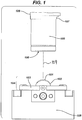
- a displacement sensor 100 may include one or more of an objective lens 106, a laser beam source 107 and a camera 108.
- a laser beam 109 may be focused onto a targeted surface.
- an objective lens 106 may oscillate up and down changing a laser beam 109 focal point until a camera 108 determines at which position an objective lens 106 may obtain a sharp focus.
- a laser beam 109 may be reflected off a surface onto a camera 108, wherein a target height of a displacement sensor 100 may be determined.
- a displacement sensor 100 is capable of taking a displacement measurement of a surface.
- a displacement sensor 100 may have an operating range of 30 mm and may measure thickness from plus 1mm to minus 1 mm, while maintaining adequate displacement accuracy.
- a displacement sensor 100 may include model Keyence LT-9030M (Japan) or any other displacement sensor known to those in the art.
- a forming optic mandrel 102 is used to form a back curve of a lens 101.
- a forming optic mandrel 102 may sit on a metal frame 103, together comprising a forming optic assembly 104.
- a kinematic mounting device 105 may fasten a forming optic assembly 104 in place.
- a kinematic mount 105 may be defined as a mechanism for mounting an object in a fixed position relative to another.
- utilizing a kinematic mount 105 and a mounting technique for implementing the same may allow for a forming optic assembly 104 to maintain a precise position each time a forming optic assembly 104 may be mounted upon a kinematic mount 105.
- a displacement sensor 100 may take a reference measurement on a forming optic 102, it may be functionally important for a forming optic assembly 104 to maintain a precise mounting position each time, to obtain accurate measurement data.
- a forming optic assembly 104 maintaining a precise position may allow for one or both of formation and measurement of a lens 101 to occur on an exact place of a forming optic 102 each time, and measurement of a forming optic 102 to occur in an exact position each time.
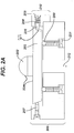
- Fig. 2A illustrates a cross section of a kinematic mount 205 and a forming optic assembly 204 wherein, a forming optic assembly 204 includes both of a forming optic mandrel 202 and a metal frame 203.
- Fig. 2B illustrates a top view of a kinematic mount 205 and a forming optic mandrel 202.
- a top of a plate of a kinematic mount 205 may include one or multiple balls 200 included in a bore.
- a kinematic mount 205 may include one or multiple screws 201 that may aid in adjusting a ball 200 height until a ball 200 may touch a forming optic assembly 204 at a single point whereby, a forming optic assembly 204 may be leveled on a forming optic rotation axis.
- a kinematic mount 205 may include one or more of adjuster ball pins 207 and a plunger 206 that may aid in securing a kinematic mount 205 in place.
- a spring pin assembly 210 may include one or more of a plunger 206 that may ride in a groove, a spring 208 that may sit behind a plunger 206, and a spring pin assembly screw 209 that may captivate a spring 208.
- a plunger 206 may move in and out freely, wherein a plunger 206 may engage a forming optic assembly 204 into a position by pushing itself into a notch 211. More specifically, in some embodiments, for example, a notch 211 may secure a forming optic assembly 204 to remain clocked in a right angle as a spring 208 may push a plunger 206 into a notch 211. In some additional embodiments, a spring pin assembly 210 via a plunger 206, may push a forming optic assembly 204 in a certain direction (e.g., left or right) wherein, an edge of a forming optic assembly 204 may impinge on one or both adjuster ball pins 207. Furthermore, in some embodiments, adjusting an adjuster ball pin 207 may allow adjustment of an entire X, Y position of a forming optic assembly 204.
- a negative atmospheric pressure pump is used to supply negative atmospheric pressure, or vacuum pressure 212 to a space between a forming optic assembly 204 and a kinematic mount 205 through a forming optic assembly rotation axis.
- a vacuum may be used to releasably secure a forming optic assembly 204 down onto one or more balls 200 but not, however, so that one or both of a spring 208 and a plunger 206 may be inhibited from pushing a forming optic assembly 204 against one or both adjuster ball pins 207.
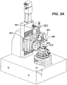
- Fig. 3A illustrates a side view of a metrology apparatus including a sensor rotation axis 301 and multiple displacement sensor 300 adjusters.
- Fig. 3B illustrates a closer-up side view of a metrology apparatus including a forming optic rotation axis 308 and multiple forming optic 302 adjusters.
- a sensor 300 may rotate via a sensor rotation axis 301 and a forming optic assembly 304 mounted upon a kinematic mounting device 305, may rotate via a forming optic rotation axis 308 for the full duration of a measurement.
- a forming optic rotation axis 308 and sensor rotation axis 301 both are state of the art air bearing motorized servo axis', which allows for limited radial run out and axial movement of both axis'.
- a displacement sensor 300 and a forming optic mandrel 302 may be aligned wherein a sensor 300 may be centered above a center sphere of a forming optic mandrel 302 during a measurement.
- a displacement sensor 300 may be aligned manually by adjusting one or more of a sensor x adjuster 303, a sensor y adjuster 306, and a sensor z adjuster 307.
- a sensor x adjuster 303 may aid in aligning a displacement sensor 300 by allowing movement of a sensor 300 in and out along an x-axis.
- a sensor y adjuster 306 may aid in aligning a displacement sensor 300 by moving a sensor 300 in and out along a y-axis.
- a sensor z adjuster 307 may aid in aligning a displacement sensor 300 by moving a sensor 300 up and down along a z-axis.
- a sensor z adjuster 407 may aid in moving a displacement sensor 300 to a specified working radius, preferably of 30mm above a forming optic mandrel 302.
- a forming optic assembly 304 via adjustment of a kinematic mount 305 may be aligned manually by adjusting one or both of a forming optic x adjuster 309 and a forming optic y adjuster 310.
- adjustment of one or both of a forming optic x adjuster 309 and forming optic y adjuster 310 may take eccentricity out of a forming optic assembly 304 when mounted upon a forming optic rotation axis 308 wherein, a forming optic 302 may rotate on a center of a forming optic rotation axis 308.
- a displacement sensor 300 when performing measurements, may be rotated via a sensor rotation axis 301 to a point of approximately 65 degrees from a position relative to where a sensor 300 may be located when positioned directly above a forming optic mandrel 302. Accordingly, in some embodiments, a displacement sensor's 300 starting angle for taking a measurement may be greater or smaller with respect to one or both of a size of a surface diameter and a size of a surface portion. For example, in some embodiments, a starting angle of a displacement sensor 300 may be smaller for measuring an optic zone of a lens as opposed to measuring a whole lens, and as opposed to measuring a forming optic 302 without a lens.
- a forming optic rotation axis 308 may begin to rotate continuously during a measurement.
- a displacement sensor 300 may zero itself out on a remaining portion of a forming optic 302 outside of a lens edge.
- a displacement sensor 300 may take a data point measurement in spherical radial coordinates, for every 1 ⁇ 4 degree of rotation made of a forming optic rotation axis 308 thereby, collecting a total of 1440 data points per one complete rotation of a rotation axis 308.
- a displacement value may be determined for each ⁇ ° of rotation of a forming optic rotation axis 308 wherein, a displacement value may be determined.
- Rho values may be calculated such that, evenly incremented axial rings of data may be collected during a measurement wherein, one ring of data may require one rotation of a forming optic assembly 304 followed by a subsequent rotation, as a sensor rotation axis 301 simultaneously moves to a next p position.
- a sensor rotation axis 301 in conjunction with a displacement sensor 300 may move upward to each ⁇ position wherein, data points may be collected for each axial ring such as, for example, up to 140 axial rings during a measurement.
- a flowchart illustrates method steps that may be implemented to acquire metrology data and determine an axial thickness of an un-hydrated ophthalmic lens.
- an ophthalmic lens may be made and need to be measured to determine whether a lens meets desired specifications.
- a metrology apparatus may be aligned, so that a displacement sensor may be directly centered above a center of a forming optic sphere.
- a reference measurement may be performed of a forming optic mandrel without a lens on the forming optic's surface (M1).
- a measurement may be performed of a lens formed upon a same forming optic (M2) aforementioned at 401, wherein a reference measurement of a forming optic may have been performed.
- metrology data acquired from measurements M1 and M2 may be converted from spherical radial coordinates into Cartesian coordinates (refer to Fig. 5 ).
- a lens axial thickness (M3) value may be calculated wherein a M3 value may be equal to a difference of a Ml metrology data file subtracted from a M2 metrology data file.
- Fig. 5A illustrates a displacement sensor 500 performing a measurement of a lens 501 upon a forming optic mandrel 502 wherein, metrology data is represented in spherical radial coordinates.
- Fig. 5B illustrates a top view of a forming optic mandrel 502 wherein, metrology data is represented in spherical radial coordinates.
- a conversion of spherical radial coordinates recorded may be converted into axial thickness in Cartesian Coordinates, such as X, Y coordinates utilizing one or more of various mathematical calculations. The following represent some exemplary calculations that may be used, wherein:
- FIG. 6 illustrates a controller 600 that may be used to implement some aspects of the present invention.
- a processor unit 601 which may include one or more processors, coupled to a communication device 602 configured to communicate via a communication network.
- the communication device 602 may be used to communicate, for example, with one or more controller apparatus or manufacturing equipment components.
- a processor 601 may also be used in communication with a storage device 603.
- a storage device 603 may comprise any appropriate information storage device, including combinations of magnetic storage devices (e.g., magnetic tape and hard disk drives), optical storage devices, and/or semiconductor memory devices such as Random Access Memory (RAM) devices and Read Only Memory (ROM) devices.
- RAM Random Access Memory
- ROM Read Only Memory
- a storage device 603 may store an executable software program 604 for controlling a processor 601.
- a processor 601 performs instructions of a software program 604, and thereby operates in accordance with the present invention such as, for example, the aforementioned method steps.
- a processor 601 may receive information descriptive of metrology data including a forming optic reference measurement, a lens measurement, and the like.
- a storage device 603 may also store related data in one or more databases 605 and 606.
Claims (6)
- Vorrichtung zum Vermessen einer nichthydratisierten ophthalmischen Linse (101), wobei die Vorrichtung umfasst:eine kinematische Halterung (205), gestaltet zum Halten einer optischen Formwerkzeugbaugruppe (204) darauf, die einen optischen Formwerkzeugkern (202) umfasst, und zum lösbaren Befestigen der optischen Formwerkzeugbaugruppe durch eine Atmosphärenunterdruckpumpe, die einen atmosphärischen Unterdruck oder Vakuumdruck (212) an einen Raum zwischen der optischen Formwerkzeugbaugruppe und der kinematische Halterung durch die Drehachse der optischen Formwerkzeugbaugruppe liefert;eine Messvorrichtung, die einen Wegsensor (100) umfasst, der fähig ist, eine Wegmessung in Antwort auf ein digitales Signal aufzunehmen;einen Computerprozessor (601) in digitaler Verbindung mit der Messvorrichtung;eine digitale Speichermedienvorrichtung (603) in Verbindung mit dem Computerprozessor, die einen ausführbaren Softwarecode darauf gespeichert aufweist, der, wenn auf Anweisung auf dem Computerprozessor ausgeführt und in Verbindung mit der Messvorrichtung:digitale Daten speichert, die für einen Bestand an Messdaten beschreibend sind, wobei die Messdaten einen Messwert umfassen;digitale Eingangs-Messdaten empfängt, die für Messungen der Messvorrichtung beschreibend sind, umfassend eine Referenzmessung M1 des optischen Formwerkzeugkerns ohne eine darauf gebildete nichthydratisierte ophthalmische Linse, und eine Messung M2 der auf dem gleichen optischen Formwerkzeugkern gebildeten nichthydratisierten ophthalmischen Linse; undeinen axialen Dickenwert der nichthydratisierten ophthalmischen Linse durch Subtrahieren der M1-Messdaten von den M2-Messdaten berechnet.
- Vorrichtung gemäß Anspruch 1, zusätzlich umfassend eine Kommunikationsvorrichtung, die den Computerprozessor mit einem verteilten Netzwerk verbindet, wobei der ausführbare Softwarecode ferner funktionsfähig ist, Messdaten, die für einen aktuellen Bestand in der Messvorrichtung beschreibend sind, zu übertragen.
- Vorrichtung gemäß Anspruch 1, wobei die Messwerte durch eine Sammlung von Datenpunkten definiert sind.
- Vorrichtung gemäß Anspruch 3, wobei die Sammlung von Datenpunkten sphärische Radialkoordinaten umfasst.
- Vorrichtung gemäß Anspruch 4, wobei die sphärischen Radialkoordinaten in kartesische Axialkoordinaten umgewandelt werden können.
- Verfahren zum Vermessen einer nichthydratisierten ophthalmischen Linse (101), wobei das Verfahren umfasst:Bereitstellen der Vorrichtung zum Vermessen einer ophthalmischen Linse gemäß Anspruch 1;Verwenden der Atmosphärenunterdruckpumpe zum Liefern eines atmosphärischen Unterdrucks oder Vakuumdrucks an den Raum zwischen der optischen Formwerkzeugbaugruppe und der kinematischen Halterung durch die Drehachse der optischen Formwerkzeugbaugruppe;Durchführen einer Referenzmessung M1 des optischen Formwerkzeugkerns ohne eine darauf gebildete nichthydratisierte ophthalmische Linse mithilfe der Vorrichtung gemäß Anspruch 1;Durchführen einer Messung M2 der auf dem gleichen optischen Formwerkzeugkern gebildeten nichthydratisierten ophthalmischen Linse mithilfe der Vorrichtung gemäß Anspruch 1; undBerechnen der axialen Dicke der nichthydratisierten ophthalmischen Linse durch Subtrahieren der M1-Messdaten von den M2-Messdaten.
Applications Claiming Priority (3)
| Application Number | Priority Date | Filing Date | Title |
|---|---|---|---|
| US41814810P | 2010-11-30 | 2010-11-30 | |
| US13/305,666 US20120133958A1 (en) | 2010-11-30 | 2011-11-28 | Laser confocal sensor metrology system |
| PCT/US2011/062408 WO2012075016A1 (en) | 2010-11-30 | 2011-11-29 | Laser confocal sensor metrology system |
Publications (2)
| Publication Number | Publication Date |
|---|---|
| EP2646788A1 EP2646788A1 (de) | 2013-10-09 |
| EP2646788B1 true EP2646788B1 (de) | 2019-12-25 |
Family
ID=46126447
Family Applications (2)
| Application Number | Title | Priority Date | Filing Date |
|---|---|---|---|
| EP11801902.5A Active EP2646788B1 (de) | 2010-11-30 | 2011-11-29 | Vorrichtung und verfahren zum vermessen von ophtalmischen linsen |
| EP11808020.9A Active EP2646790B1 (de) | 2010-11-30 | 2011-11-29 | Konfokales laser-sensormesssystem |
Family Applications After (1)
| Application Number | Title | Priority Date | Filing Date |
|---|---|---|---|
| EP11808020.9A Active EP2646790B1 (de) | 2010-11-30 | 2011-11-29 | Konfokales laser-sensormesssystem |
Country Status (13)
| Country | Link |
|---|---|
| US (3) | US20120133957A1 (de) |
| EP (2) | EP2646788B1 (de) |
| JP (2) | JP5922143B2 (de) |
| KR (2) | KR101886616B1 (de) |
| CN (3) | CN106197297B (de) |
| AR (2) | AR084041A1 (de) |
| AU (2) | AU2011336778B2 (de) |
| BR (2) | BR112013013437A2 (de) |
| CA (2) | CA2819348C (de) |
| RU (2) | RU2604564C2 (de) |
| SG (2) | SG190414A1 (de) |
| TW (2) | TWI558974B (de) |
| WO (2) | WO2012075013A1 (de) |
Families Citing this family (32)
| Publication number | Priority date | Publication date | Assignee | Title |
|---|---|---|---|---|
| ES2788853T3 (es) | 2010-12-06 | 2020-10-23 | 3Shape As | Sistema con integración de interfaz de usuario 3D |
| US9465236B2 (en) * | 2013-03-15 | 2016-10-11 | Johnson & Johnson Vision Care, Inc. | Ophthalmic devices incorporating photonic elements |
| US20140268029A1 (en) * | 2013-03-15 | 2014-09-18 | Johnson & Johnson Vision Care, Inc. | Method and ophthalmic device for providing visual representations to a user |
| IL231446A0 (en) * | 2013-03-15 | 2014-08-31 | Johnson & Johnson Vision Care | Eye method and device for providing visual representations to a user |
| DE102013219838B4 (de) * | 2013-09-30 | 2015-11-26 | Carl Zeiss Ag | Verfahren und System für das Ermitteln der räumlichen Struktur eines Gegenstands |
| WO2014177632A1 (de) | 2013-05-02 | 2014-11-06 | Carl Zeiss Vision International Gmbh | Verfahren und system für das ermitteln der räumlichen struktur eines gegenstands |
| CN103610511B (zh) * | 2013-12-05 | 2015-06-03 | 天津开发区合普工贸有限公司 | 一种实验动物激光眼角膜切割装置 |
| CN103631098B (zh) * | 2013-12-23 | 2016-08-17 | 成都虹博宇光电科技有限公司 | 一种非接触式光刻机调平调焦系统、方法和光刻机 |
| US9645412B2 (en) | 2014-11-05 | 2017-05-09 | Johnson & Johnson Vision Care Inc. | Customized lens device and method |
| CN104613881A (zh) * | 2015-02-12 | 2015-05-13 | 江苏宇迪光学股份有限公司 | 一种基于双面共焦的透镜中心厚度测量装置及测量方法 |
| EP3059575B1 (de) * | 2015-02-20 | 2020-11-25 | Alcon Inc. | Verfahren zur Bestimmung der Qualität einer Oberfläche einer ophthalmischen Linse |
| US9863842B2 (en) | 2015-09-24 | 2018-01-09 | Novartis Ag | Method for characterizing an ophthalmic lens |
| CN106556349A (zh) * | 2015-09-24 | 2017-04-05 | 上海思信科学仪器有限公司 | 水膜厚度测量仪 |
| CN106556348A (zh) * | 2015-09-24 | 2017-04-05 | 上海思信科学仪器有限公司 | 蓝宝石厚度测量仪 |
| US10607335B2 (en) * | 2016-06-28 | 2020-03-31 | Johnson & Johnson Vision Care, Inc. | Systems and methods of using absorptive imaging metrology to measure the thickness of ophthalmic lenses |
| US10830666B2 (en) * | 2016-10-31 | 2020-11-10 | Alcon Inc. | Contact lens inspection method and system |
| CN106483049B (zh) * | 2016-11-01 | 2019-08-13 | 浙江省计量科学研究院 | 一种刮板细度计示值误差的非接触自动校准装置及方法 |
| TWI652469B (zh) | 2017-09-15 | 2019-03-01 | 財團法人國家實驗硏究院 | 用於檢驗隱形眼鏡的檢驗裝置與方法及用於檢驗含水元件的檢驗裝置 |
| CN108562228B (zh) * | 2018-06-08 | 2024-03-26 | 昆山迈致治具科技有限公司 | 一种自动化连续测试设备 |
| CN109579713A (zh) * | 2018-08-17 | 2019-04-05 | 深圳中科飞测科技有限公司 | 测量设备及测量方法 |
| CN109000571B (zh) * | 2018-09-11 | 2021-05-14 | 中国科学院光电技术研究所 | 一种厚度一致性检测装置 |
| CN109365312B (zh) * | 2018-09-16 | 2020-10-13 | 嘉兴麦瑞网络科技有限公司 | 一种隐形眼镜大数据管理筛分流水线 |
| CN109342024B (zh) * | 2018-09-16 | 2020-10-27 | 林玲 | 一种隐形眼镜筛分设备及其筛分方法 |
| FR3090088B1 (fr) * | 2018-12-12 | 2021-06-18 | Saint Gobain | Procédé de mesure des écarts géométriques entre les surfaces incurvées d'une pluralité de matériaux à évaluer et une surface incurvée d’un matériau de référence |
| US11635344B2 (en) * | 2019-02-01 | 2023-04-25 | Optikos Corporation | Portable optic metrology thermal chamber module and method therefor |
| CN110425988A (zh) * | 2019-08-16 | 2019-11-08 | 宾努克斯科技(佛山)有限公司 | 一种相对激光测厚仪 |
| KR102296485B1 (ko) * | 2020-02-21 | 2021-08-31 | 임완철 | 광학 검사 장비의 스테이지 자동정렬 구조 |
| CN113804411A (zh) * | 2020-06-16 | 2021-12-17 | 亿美Ai私人有限公司 | 用于检测干式眼科透镜的屈光力的系统及方法 |
| CN111895924B (zh) * | 2020-07-15 | 2022-03-11 | 广州精点科技有限公司 | 一种镜片厚度自动测量装置 |
| US11835418B2 (en) * | 2021-09-30 | 2023-12-05 | Opto-Alignment Technology, Inc. | Simultaneous multi-surface non-contact optical profiler |
| US11761756B2 (en) | 2022-01-27 | 2023-09-19 | Zhejiang University | Method and device for simultaneously detecting surface shapes and thickness distribution of inner and outer walls of thin-wall rotating body |
| CN114440790B (zh) * | 2022-01-27 | 2022-11-01 | 浙江大学 | 同时检测薄壁回转体内外壁面形与厚度分布的方法与装置 |
Citations (2)
| Publication number | Priority date | Publication date | Assignee | Title |
|---|---|---|---|---|
| WO2009025848A2 (en) * | 2007-08-21 | 2009-02-26 | Johnson & Johnson Vision Care, Inc. | Apparatus for formation of an ophthalmic lens precursor |
| US20100238550A1 (en) * | 2009-03-17 | 2010-09-23 | Hon Hai Precision Industry Co., Ltd. | Lens module fixing device |
Family Cites Families (41)
| Publication number | Priority date | Publication date | Assignee | Title |
|---|---|---|---|---|
| US3804523A (en) * | 1972-09-29 | 1974-04-16 | American Hydrophilics Corp | Radiuscope thickness adaptor |
| DE2453364C3 (de) * | 1973-11-09 | 1979-02-22 | Hitachi, Ltd., Tokio | Automatische Fokussiervorrichtung |
| US4403420A (en) * | 1981-07-27 | 1983-09-13 | Coburn Optical Industries, Inc. | Digital gauge for measuring sagittal depth and thickness of lens, and related system and method |
| GB8603391D0 (en) * | 1986-02-12 | 1986-03-19 | British Aerospace | Position sensor |
| GB8625054D0 (en) | 1986-10-20 | 1986-11-26 | Renishaw Plc | Optical measuring probe |
| JPS63128210A (ja) * | 1986-11-18 | 1988-05-31 | Toyobo Co Ltd | 膜厚及び屈折率の測定方法 |
| JPH0629715B2 (ja) * | 1987-03-31 | 1994-04-20 | 松下電器産業株式会社 | 形状測定装置 |
| EP0357905A3 (de) * | 1988-08-16 | 1991-09-11 | Toray Industries, Inc. | Verfahren zur Messung des Profils eines Objektes und Apparat zu dessen Ausführung |
| DE3934744A1 (de) | 1989-10-18 | 1991-04-25 | Krupp Gmbh | Verfahren zur beruehrungslosen ermittlung der dicke transparenter werkstoffe und vorrichtung zur durchfuehrung des verfahrens |
| US5280336A (en) * | 1991-03-29 | 1994-01-18 | Optikos Corporation | Automated radius measurement apparatus |
| JPH04331345A (ja) * | 1991-05-07 | 1992-11-19 | Seiko Epson Corp | コンタクトレンズの測定装置 |
| IL107603A (en) * | 1992-12-21 | 1997-01-10 | Johnson & Johnson Vision Prod | Ophthalmic lens inspection method and apparatus |
| GR1002072B (en) * | 1992-12-21 | 1995-11-30 | Johnson & Johnson Vision Prod | Illumination system for opthalmic lens inspection. |
| US5483347A (en) * | 1993-05-19 | 1996-01-09 | Hughes Aircraft Company | Non-contact measurement apparatus using bifurcated optical fiber bundle with intermixed fibers |
| US5500732A (en) * | 1994-06-10 | 1996-03-19 | Johnson & Johnson Vision Products, Inc. | Lens inspection system and method |
| US5675406A (en) * | 1995-10-17 | 1997-10-07 | Hughes Electronics | Portable device for ensuring that a center thickness of a lens is within a predetermined tolerance |
| JP4002324B2 (ja) * | 1997-07-08 | 2007-10-31 | 株式会社ニデック | レンズ研削装置 |
| JPH11122517A (ja) * | 1997-10-13 | 1999-04-30 | Canon Inc | 撮像装置及びコンピュータ読み取り可能な記憶媒体 |
| DE19806446A1 (de) | 1998-02-17 | 1999-08-19 | Fraunhofer Ges Forschung | Verfahren und Vorrichtung zur Messung des Abstandes von Grenzflächen transparenter Medien |
| GB2337815A (en) * | 1998-05-28 | 1999-12-01 | Visionix Ltd | Thickness meter for thin transparent objects |
| JPH11348142A (ja) * | 1998-06-02 | 1999-12-21 | Seiko Epson Corp | コンタクトレンズの製造方法 |
| DE29901791U1 (de) * | 1999-02-02 | 2000-07-06 | Novartis Ag | Linsenmesseinrichtung |
| CN1264824A (zh) * | 2000-03-20 | 2000-08-30 | 华中理工大学 | 用于表面形貌测量的位移传感器 |
| US6937328B2 (en) * | 2000-08-11 | 2005-08-30 | Kabushiki Kaisha Topcon | Method for measuring refractive power and apparatus therefor |
| EP1225441A3 (de) * | 2001-01-23 | 2004-01-21 | Menicon Co., Ltd. | Verfahren zum Erkennen der Einzelheiten ophthalmischer Linsen |
| JP4101543B2 (ja) * | 2002-03-26 | 2008-06-18 | 株式会社トーメー | 眼用レンズの厚み測定方法 |
| TW200632278A (en) * | 2004-11-08 | 2006-09-16 | Matsushita Electric Ind Co Ltd | Confocal optical device and spherical aberration correcting method |
| US7433027B2 (en) * | 2004-12-22 | 2008-10-07 | Novartis Ag | Apparatus and method for detecting lens thickness |
| KR100951221B1 (ko) * | 2005-08-05 | 2010-04-05 | 미따까 고오끼 가부시끼가이샤 | 렌즈에 있어서의 표리면의 광축 편심량의 측정 방법 |
| JP4659554B2 (ja) * | 2005-08-09 | 2011-03-30 | 株式会社メニコン | 眼用レンズの製造システム及び製造方法 |
| WO2008016066A1 (fr) | 2006-07-31 | 2008-02-07 | Hoya Corporation | Dispositif et procédé de mesure de forme de lentille, procédé de production de lentille et procédé de production de lunettes |
| JP2008059548A (ja) * | 2006-08-04 | 2008-03-13 | Seiko Epson Corp | レンズ発注システム、レンズ発注方法、レンズ発注プログラム、およびレンズ発注プログラムを記録した記録媒体 |
| WO2008052701A1 (de) * | 2006-11-04 | 2008-05-08 | Trioptics Gmbh | Verfahren und vorrichtung zur bestimmung der lage einer symmetrieachse einer asphärischen linsenfläche |
| CN201043884Y (zh) * | 2007-02-13 | 2008-04-02 | 中国科学院上海光学精密机械研究所 | 全光纤斐索干涉共焦测量装置 |
| CN101266194B (zh) * | 2007-08-27 | 2011-09-07 | 温州医学院眼视光研究院 | 光学眼用镜片高精度像质检测系统 |
| US7990531B2 (en) * | 2008-06-05 | 2011-08-02 | Coopervision International Holding Company, Lp | Multi-imaging automated inspection methods and systems for wet ophthalmic lenses |
| JP5200813B2 (ja) * | 2008-09-24 | 2013-06-05 | 凸版印刷株式会社 | 測定用マークと基板エッジの距離測定方法 |
| US8240849B2 (en) * | 2009-03-31 | 2012-08-14 | Johnson & Johnson Vision Care, Inc. | Free form lens with refractive index variations |
| JP4968965B2 (ja) * | 2009-11-18 | 2012-07-04 | キヤノン株式会社 | 屈折率分布の計測方法および計測装置 |
| CN101769821A (zh) * | 2010-02-04 | 2010-07-07 | 北京理工大学 | 基于差动共焦技术的透镜折射率与厚度的测量方法及装置 |
| CN101788271A (zh) * | 2010-03-17 | 2010-07-28 | 北京理工大学 | 共焦透镜中心厚度测量方法与装置 |
-
2011
- 2011-11-28 US US13/305,655 patent/US20120133957A1/en not_active Abandoned
- 2011-11-28 US US13/305,666 patent/US20120133958A1/en not_active Abandoned
- 2011-11-29 AU AU2011336778A patent/AU2011336778B2/en not_active Ceased
- 2011-11-29 RU RU2013129857/28A patent/RU2604564C2/ru not_active IP Right Cessation
- 2011-11-29 WO PCT/US2011/062403 patent/WO2012075013A1/en active Application Filing
- 2011-11-29 CN CN201610728618.9A patent/CN106197297B/zh active Active
- 2011-11-29 KR KR1020137016086A patent/KR101886616B1/ko active IP Right Grant
- 2011-11-29 EP EP11801902.5A patent/EP2646788B1/de active Active
- 2011-11-29 BR BR112013013437A patent/BR112013013437A2/pt not_active Application Discontinuation
- 2011-11-29 EP EP11808020.9A patent/EP2646790B1/de active Active
- 2011-11-29 AU AU2011336781A patent/AU2011336781A1/en not_active Abandoned
- 2011-11-29 RU RU2013129822/28A patent/RU2584070C2/ru not_active IP Right Cessation
- 2011-11-29 CA CA2819348A patent/CA2819348C/en not_active Expired - Fee Related
- 2011-11-29 BR BR112013013440A patent/BR112013013440A2/pt not_active Application Discontinuation
- 2011-11-29 CN CN201180057505.6A patent/CN103229035B/zh active Active
- 2011-11-29 CN CN201180057535.7A patent/CN103229037B/zh active Active
- 2011-11-29 SG SG2013040613A patent/SG190414A1/en unknown
- 2011-11-29 KR KR1020137016082A patent/KR101886615B1/ko active IP Right Grant
- 2011-11-29 JP JP2013542103A patent/JP5922143B2/ja not_active Expired - Fee Related
- 2011-11-29 CA CA2819352A patent/CA2819352A1/en not_active Abandoned
- 2011-11-29 JP JP2013542104A patent/JP5922144B2/ja not_active Expired - Fee Related
- 2011-11-29 SG SG2013040340A patent/SG190881A1/en unknown
- 2011-11-29 WO PCT/US2011/062408 patent/WO2012075016A1/en active Application Filing
- 2011-11-30 AR ARP110104447A patent/AR084041A1/es not_active Application Discontinuation
- 2011-11-30 AR ARP110104448A patent/AR084042A1/es not_active Application Discontinuation
- 2011-11-30 TW TW100143906A patent/TWI558974B/zh active
- 2011-11-30 TW TW100143908A patent/TWI589850B/zh not_active IP Right Cessation
-
2013
- 2013-10-18 US US14/058,143 patent/US8953176B2/en active Active
Patent Citations (2)
| Publication number | Priority date | Publication date | Assignee | Title |
|---|---|---|---|---|
| WO2009025848A2 (en) * | 2007-08-21 | 2009-02-26 | Johnson & Johnson Vision Care, Inc. | Apparatus for formation of an ophthalmic lens precursor |
| US20100238550A1 (en) * | 2009-03-17 | 2010-09-23 | Hon Hai Precision Industry Co., Ltd. | Lens module fixing device |
Also Published As
Similar Documents
| Publication | Publication Date | Title |
|---|---|---|
| EP2646788B1 (de) | Vorrichtung und verfahren zum vermessen von ophtalmischen linsen | |
| JP2017516155A (ja) | 多層加法的技術によるアイウェア・レンズの作成 | |
| US20210016496A1 (en) | High-throughput 3d printing of customized aspheric imaging lenses | |
| AU2016273907B2 (en) | Method and apparatus for measuring the wavefront of an ophthalmic device |
Legal Events
| Date | Code | Title | Description |
|---|---|---|---|
| PUAI | Public reference made under article 153(3) epc to a published international application that has entered the european phase |
Free format text: ORIGINAL CODE: 0009012 |
|
| 17P | Request for examination filed |
Effective date: 20130628 |
|
| AK | Designated contracting states |
Kind code of ref document: A1 Designated state(s): AL AT BE BG CH CY CZ DE DK EE ES FI FR GB GR HR HU IE IS IT LI LT LU LV MC MK MT NL NO PL PT RO RS SE SI SK SM TR |
|
| DAX | Request for extension of the european patent (deleted) | ||
| REG | Reference to a national code |
Ref country code: HK Ref legal event code: DE Ref document number: 1190187 Country of ref document: HK |
|
| STAA | Information on the status of an ep patent application or granted ep patent |
Free format text: STATUS: EXAMINATION IS IN PROGRESS |
|
| 17Q | First examination report despatched |
Effective date: 20180124 |
|
| RIC1 | Information provided on ipc code assigned before grant |
Ipc: G01B 11/24 20060101ALI20190416BHEP Ipc: G01B 11/06 20060101ALI20190416BHEP Ipc: G01M 11/02 20060101AFI20190416BHEP |
|
| GRAP | Despatch of communication of intention to grant a patent |
Free format text: ORIGINAL CODE: EPIDOSNIGR1 |
|
| STAA | Information on the status of an ep patent application or granted ep patent |
Free format text: STATUS: GRANT OF PATENT IS INTENDED |
|
| INTG | Intention to grant announced |
Effective date: 20190528 |
|
| GRAJ | Information related to disapproval of communication of intention to grant by the applicant or resumption of examination proceedings by the epo deleted |
Free format text: ORIGINAL CODE: EPIDOSDIGR1 |
|
| STAA | Information on the status of an ep patent application or granted ep patent |
Free format text: STATUS: EXAMINATION IS IN PROGRESS |
|
| GRAJ | Information related to disapproval of communication of intention to grant by the applicant or resumption of examination proceedings by the epo deleted |
Free format text: ORIGINAL CODE: EPIDOSDIGR1 |
|
| GRAL | Information related to payment of fee for publishing/printing deleted |
Free format text: ORIGINAL CODE: EPIDOSDIGR3 |
|
| GRAS | Grant fee paid |
Free format text: ORIGINAL CODE: EPIDOSNIGR3 |
|
| GRAJ | Information related to disapproval of communication of intention to grant by the applicant or resumption of examination proceedings by the epo deleted |
Free format text: ORIGINAL CODE: EPIDOSDIGR1 |
|
| GRAP | Despatch of communication of intention to grant a patent |
Free format text: ORIGINAL CODE: EPIDOSNIGR1 |
|
| GRAR | Information related to intention to grant a patent recorded |
Free format text: ORIGINAL CODE: EPIDOSNIGR71 |
|
| STAA | Information on the status of an ep patent application or granted ep patent |
Free format text: STATUS: GRANT OF PATENT IS INTENDED |
|
| INTC | Intention to grant announced (deleted) | ||
| GRAA | (expected) grant |
Free format text: ORIGINAL CODE: 0009210 |
|
| STAA | Information on the status of an ep patent application or granted ep patent |
Free format text: STATUS: THE PATENT HAS BEEN GRANTED |
|
| INTG | Intention to grant announced |
Effective date: 20191023 |
|
| AK | Designated contracting states |
Kind code of ref document: B1 Designated state(s): AL AT BE BG CH CY CZ DE DK EE ES FI FR GB GR HR HU IE IS IT LI LT LU LV MC MK MT NL NO PL PT RO RS SE SI SK SM TR |
|
| REG | Reference to a national code |
Ref country code: GB Ref legal event code: FG4D |
|
| REG | Reference to a national code |
Ref country code: CH Ref legal event code: EP |
|
| REG | Reference to a national code |
Ref country code: AT Ref legal event code: REF Ref document number: 1217648 Country of ref document: AT Kind code of ref document: T Effective date: 20200115 |
|
| REG | Reference to a national code |
Ref country code: DE Ref legal event code: R096 Ref document number: 602011064249 Country of ref document: DE |
|
| REG | Reference to a national code |
Ref country code: IE Ref legal event code: FG4D |
|
| REG | Reference to a national code |
Ref country code: NL Ref legal event code: MP Effective date: 20191225 |
|
| PG25 | Lapsed in a contracting state [announced via postgrant information from national office to epo] |
Ref country code: GR Free format text: LAPSE BECAUSE OF FAILURE TO SUBMIT A TRANSLATION OF THE DESCRIPTION OR TO PAY THE FEE WITHIN THE PRESCRIBED TIME-LIMIT Effective date: 20200326 Ref country code: LT Free format text: LAPSE BECAUSE OF FAILURE TO SUBMIT A TRANSLATION OF THE DESCRIPTION OR TO PAY THE FEE WITHIN THE PRESCRIBED TIME-LIMIT Effective date: 20191225 Ref country code: FI Free format text: LAPSE BECAUSE OF FAILURE TO SUBMIT A TRANSLATION OF THE DESCRIPTION OR TO PAY THE FEE WITHIN THE PRESCRIBED TIME-LIMIT Effective date: 20191225 Ref country code: BG Free format text: LAPSE BECAUSE OF FAILURE TO SUBMIT A TRANSLATION OF THE DESCRIPTION OR TO PAY THE FEE WITHIN THE PRESCRIBED TIME-LIMIT Effective date: 20200325 Ref country code: NO Free format text: LAPSE BECAUSE OF FAILURE TO SUBMIT A TRANSLATION OF THE DESCRIPTION OR TO PAY THE FEE WITHIN THE PRESCRIBED TIME-LIMIT Effective date: 20200325 Ref country code: SE Free format text: LAPSE BECAUSE OF FAILURE TO SUBMIT A TRANSLATION OF THE DESCRIPTION OR TO PAY THE FEE WITHIN THE PRESCRIBED TIME-LIMIT Effective date: 20191225 Ref country code: LV Free format text: LAPSE BECAUSE OF FAILURE TO SUBMIT A TRANSLATION OF THE DESCRIPTION OR TO PAY THE FEE WITHIN THE PRESCRIBED TIME-LIMIT Effective date: 20191225 |
|
| REG | Reference to a national code |
Ref country code: LT Ref legal event code: MG4D |
|
| PG25 | Lapsed in a contracting state [announced via postgrant information from national office to epo] |
Ref country code: RS Free format text: LAPSE BECAUSE OF FAILURE TO SUBMIT A TRANSLATION OF THE DESCRIPTION OR TO PAY THE FEE WITHIN THE PRESCRIBED TIME-LIMIT Effective date: 20191225 Ref country code: HR Free format text: LAPSE BECAUSE OF FAILURE TO SUBMIT A TRANSLATION OF THE DESCRIPTION OR TO PAY THE FEE WITHIN THE PRESCRIBED TIME-LIMIT Effective date: 20191225 |
|
| PG25 | Lapsed in a contracting state [announced via postgrant information from national office to epo] |
Ref country code: AL Free format text: LAPSE BECAUSE OF FAILURE TO SUBMIT A TRANSLATION OF THE DESCRIPTION OR TO PAY THE FEE WITHIN THE PRESCRIBED TIME-LIMIT Effective date: 20191225 |
|
| PG25 | Lapsed in a contracting state [announced via postgrant information from national office to epo] |
Ref country code: NL Free format text: LAPSE BECAUSE OF FAILURE TO SUBMIT A TRANSLATION OF THE DESCRIPTION OR TO PAY THE FEE WITHIN THE PRESCRIBED TIME-LIMIT Effective date: 20191225 Ref country code: PT Free format text: LAPSE BECAUSE OF FAILURE TO SUBMIT A TRANSLATION OF THE DESCRIPTION OR TO PAY THE FEE WITHIN THE PRESCRIBED TIME-LIMIT Effective date: 20200520 Ref country code: RO Free format text: LAPSE BECAUSE OF FAILURE TO SUBMIT A TRANSLATION OF THE DESCRIPTION OR TO PAY THE FEE WITHIN THE PRESCRIBED TIME-LIMIT Effective date: 20191225 Ref country code: CZ Free format text: LAPSE BECAUSE OF FAILURE TO SUBMIT A TRANSLATION OF THE DESCRIPTION OR TO PAY THE FEE WITHIN THE PRESCRIBED TIME-LIMIT Effective date: 20191225 Ref country code: EE Free format text: LAPSE BECAUSE OF FAILURE TO SUBMIT A TRANSLATION OF THE DESCRIPTION OR TO PAY THE FEE WITHIN THE PRESCRIBED TIME-LIMIT Effective date: 20191225 |
|
| PG25 | Lapsed in a contracting state [announced via postgrant information from national office to epo] |
Ref country code: SK Free format text: LAPSE BECAUSE OF FAILURE TO SUBMIT A TRANSLATION OF THE DESCRIPTION OR TO PAY THE FEE WITHIN THE PRESCRIBED TIME-LIMIT Effective date: 20191225 Ref country code: IS Free format text: LAPSE BECAUSE OF FAILURE TO SUBMIT A TRANSLATION OF THE DESCRIPTION OR TO PAY THE FEE WITHIN THE PRESCRIBED TIME-LIMIT Effective date: 20200425 Ref country code: SM Free format text: LAPSE BECAUSE OF FAILURE TO SUBMIT A TRANSLATION OF THE DESCRIPTION OR TO PAY THE FEE WITHIN THE PRESCRIBED TIME-LIMIT Effective date: 20191225 |
|
| REG | Reference to a national code |
Ref country code: DE Ref legal event code: R097 Ref document number: 602011064249 Country of ref document: DE |
|
| PG25 | Lapsed in a contracting state [announced via postgrant information from national office to epo] |
Ref country code: ES Free format text: LAPSE BECAUSE OF FAILURE TO SUBMIT A TRANSLATION OF THE DESCRIPTION OR TO PAY THE FEE WITHIN THE PRESCRIBED TIME-LIMIT Effective date: 20191225 Ref country code: DK Free format text: LAPSE BECAUSE OF FAILURE TO SUBMIT A TRANSLATION OF THE DESCRIPTION OR TO PAY THE FEE WITHIN THE PRESCRIBED TIME-LIMIT Effective date: 20191225 |
|
| PLBE | No opposition filed within time limit |
Free format text: ORIGINAL CODE: 0009261 |
|
| STAA | Information on the status of an ep patent application or granted ep patent |
Free format text: STATUS: NO OPPOSITION FILED WITHIN TIME LIMIT |
|
| REG | Reference to a national code |
Ref country code: AT Ref legal event code: MK05 Ref document number: 1217648 Country of ref document: AT Kind code of ref document: T Effective date: 20191225 |
|
| PG25 | Lapsed in a contracting state [announced via postgrant information from national office to epo] |
Ref country code: SI Free format text: LAPSE BECAUSE OF FAILURE TO SUBMIT A TRANSLATION OF THE DESCRIPTION OR TO PAY THE FEE WITHIN THE PRESCRIBED TIME-LIMIT Effective date: 20191225 |
|
| 26N | No opposition filed |
Effective date: 20200928 |
|
| PG25 | Lapsed in a contracting state [announced via postgrant information from national office to epo] |
Ref country code: AT Free format text: LAPSE BECAUSE OF FAILURE TO SUBMIT A TRANSLATION OF THE DESCRIPTION OR TO PAY THE FEE WITHIN THE PRESCRIBED TIME-LIMIT Effective date: 20191225 |
|
| PG25 | Lapsed in a contracting state [announced via postgrant information from national office to epo] |
Ref country code: PL Free format text: LAPSE BECAUSE OF FAILURE TO SUBMIT A TRANSLATION OF THE DESCRIPTION OR TO PAY THE FEE WITHIN THE PRESCRIBED TIME-LIMIT Effective date: 20191225 |
|
| PG25 | Lapsed in a contracting state [announced via postgrant information from national office to epo] |
Ref country code: MC Free format text: LAPSE BECAUSE OF FAILURE TO SUBMIT A TRANSLATION OF THE DESCRIPTION OR TO PAY THE FEE WITHIN THE PRESCRIBED TIME-LIMIT Effective date: 20191225 |
|
| REG | Reference to a national code |
Ref country code: CH Ref legal event code: PL |
|
| REG | Reference to a national code |
Ref country code: HK Ref legal event code: WD Ref document number: 1190187 Country of ref document: HK |
|
| PG25 | Lapsed in a contracting state [announced via postgrant information from national office to epo] |
Ref country code: LU Free format text: LAPSE BECAUSE OF NON-PAYMENT OF DUE FEES Effective date: 20201129 |
|
| REG | Reference to a national code |
Ref country code: BE Ref legal event code: MM Effective date: 20201130 |
|
| PG25 | Lapsed in a contracting state [announced via postgrant information from national office to epo] |
Ref country code: CH Free format text: LAPSE BECAUSE OF NON-PAYMENT OF DUE FEES Effective date: 20201130 Ref country code: LI Free format text: LAPSE BECAUSE OF NON-PAYMENT OF DUE FEES Effective date: 20201130 |
|
| PG25 | Lapsed in a contracting state [announced via postgrant information from national office to epo] |
Ref country code: TR Free format text: LAPSE BECAUSE OF FAILURE TO SUBMIT A TRANSLATION OF THE DESCRIPTION OR TO PAY THE FEE WITHIN THE PRESCRIBED TIME-LIMIT Effective date: 20191225 Ref country code: MT Free format text: LAPSE BECAUSE OF FAILURE TO SUBMIT A TRANSLATION OF THE DESCRIPTION OR TO PAY THE FEE WITHIN THE PRESCRIBED TIME-LIMIT Effective date: 20191225 Ref country code: CY Free format text: LAPSE BECAUSE OF FAILURE TO SUBMIT A TRANSLATION OF THE DESCRIPTION OR TO PAY THE FEE WITHIN THE PRESCRIBED TIME-LIMIT Effective date: 20191225 |
|
| PG25 | Lapsed in a contracting state [announced via postgrant information from national office to epo] |
Ref country code: MK Free format text: LAPSE BECAUSE OF FAILURE TO SUBMIT A TRANSLATION OF THE DESCRIPTION OR TO PAY THE FEE WITHIN THE PRESCRIBED TIME-LIMIT Effective date: 20191225 |
|
| PG25 | Lapsed in a contracting state [announced via postgrant information from national office to epo] |
Ref country code: BE Free format text: LAPSE BECAUSE OF NON-PAYMENT OF DUE FEES Effective date: 20201130 |
|
| PGFP | Annual fee paid to national office [announced via postgrant information from national office to epo] |
Ref country code: FR Payment date: 20221010 Year of fee payment: 12 |
|
| PGFP | Annual fee paid to national office [announced via postgrant information from national office to epo] |
Ref country code: IT Payment date: 20221011 Year of fee payment: 12 Ref country code: IE Payment date: 20221011 Year of fee payment: 12 Ref country code: GB Payment date: 20221006 Year of fee payment: 12 Ref country code: DE Payment date: 20220621 Year of fee payment: 12 |