EP2645708B1 - Verfahren zur Korrektur von streifenartigem Rauschen eines aufgenommenen Bildes, Photographiervorrichtung und elektronische Endoskopvorrichtung - Google Patents
Verfahren zur Korrektur von streifenartigem Rauschen eines aufgenommenen Bildes, Photographiervorrichtung und elektronische Endoskopvorrichtung Download PDFInfo
- Publication number
- EP2645708B1 EP2645708B1 EP13161706.0A EP13161706A EP2645708B1 EP 2645708 B1 EP2645708 B1 EP 2645708B1 EP 13161706 A EP13161706 A EP 13161706A EP 2645708 B1 EP2645708 B1 EP 2645708B1
- Authority
- EP
- European Patent Office
- Prior art keywords
- image
- pixels
- color
- correction
- stripe noise
- Prior art date
- Legal status (The legal status is an assumption and is not a legal conclusion. Google has not performed a legal analysis and makes no representation as to the accuracy of the status listed.)
- Not-in-force
Links
Images


Classifications
-
- H—ELECTRICITY
- H04—ELECTRIC COMMUNICATION TECHNIQUE
- H04N—PICTORIAL COMMUNICATION, e.g. TELEVISION
- H04N9/00—Details of colour television systems
- H04N9/64—Circuits for processing colour signals
- H04N9/646—Circuits for processing colour signals for image enhancement, e.g. vertical detail restoration, cross-colour elimination, contour correction, chrominance trapping filters
-
- H—ELECTRICITY
- H04—ELECTRIC COMMUNICATION TECHNIQUE
- H04N—PICTORIAL COMMUNICATION, e.g. TELEVISION
- H04N25/00—Circuitry of solid-state image sensors [SSIS]; Control thereof
-
- H—ELECTRICITY
- H04—ELECTRIC COMMUNICATION TECHNIQUE
- H04N—PICTORIAL COMMUNICATION, e.g. TELEVISION
- H04N25/00—Circuitry of solid-state image sensors [SSIS]; Control thereof
- H04N25/60—Noise processing, e.g. detecting, correcting, reducing or removing noise
- H04N25/67—Noise processing, e.g. detecting, correcting, reducing or removing noise applied to fixed-pattern noise, e.g. non-uniformity of response
- H04N25/671—Noise processing, e.g. detecting, correcting, reducing or removing noise applied to fixed-pattern noise, e.g. non-uniformity of response for non-uniformity detection or correction
- H04N25/677—Noise processing, e.g. detecting, correcting, reducing or removing noise applied to fixed-pattern noise, e.g. non-uniformity of response for non-uniformity detection or correction for reducing the column or line fixed pattern noise
-
- G—PHYSICS
- G02—OPTICS
- G02F—OPTICAL DEVICES OR ARRANGEMENTS FOR THE CONTROL OF LIGHT BY MODIFICATION OF THE OPTICAL PROPERTIES OF THE MEDIA OF THE ELEMENTS INVOLVED THEREIN; NON-LINEAR OPTICS; FREQUENCY-CHANGING OF LIGHT; OPTICAL LOGIC ELEMENTS; OPTICAL ANALOGUE/DIGITAL CONVERTERS
- G02F1/00—Devices or arrangements for the control of the intensity, colour, phase, polarisation or direction of light arriving from an independent light source, e.g. switching, gating or modulating; Non-linear optics
- G02F1/01—Devices or arrangements for the control of the intensity, colour, phase, polarisation or direction of light arriving from an independent light source, e.g. switching, gating or modulating; Non-linear optics for the control of the intensity, phase, polarisation or colour
- G02F1/13—Devices or arrangements for the control of the intensity, colour, phase, polarisation or direction of light arriving from an independent light source, e.g. switching, gating or modulating; Non-linear optics for the control of the intensity, phase, polarisation or colour based on liquid crystals, e.g. single liquid crystal display cells
- G02F1/133—Constructional arrangements; Operation of liquid crystal cells; Circuit arrangements
- G02F1/1333—Constructional arrangements; Manufacturing methods
- G02F1/1347—Arrangement of liquid crystal layers or cells in which the final condition of one light beam is achieved by the addition of the effects of two or more layers or cells
- G02F1/13471—Arrangement of liquid crystal layers or cells in which the final condition of one light beam is achieved by the addition of the effects of two or more layers or cells in which all the liquid crystal cells or layers remain transparent, e.g. FLC, ECB, DAP, HAN, TN, STN, SBE-LC cells
- G02F1/13473—Arrangement of liquid crystal layers or cells in which the final condition of one light beam is achieved by the addition of the effects of two or more layers or cells in which all the liquid crystal cells or layers remain transparent, e.g. FLC, ECB, DAP, HAN, TN, STN, SBE-LC cells for wavelength filtering or for colour display without the use of colour mosaic filters
-
- H—ELECTRICITY
- H04—ELECTRIC COMMUNICATION TECHNIQUE
- H04N—PICTORIAL COMMUNICATION, e.g. TELEVISION
- H04N23/00—Cameras or camera modules comprising electronic image sensors; Control thereof
- H04N23/50—Constructional details
- H04N23/555—Constructional details for picking-up images in sites, inaccessible due to their dimensions or hazardous conditions, e.g. endoscopes or borescopes
Definitions
- the present invention relates to a stripe noise correction method of a captured image and a photographing apparatus.
- a solid-state imaging device for photographing a color image includes a plurality of pixels (photo-diodes) arranged on a semiconductor substrate in a two-dimensional array type. And, in the solid-state imaging device, a color filter is stacked on each of the pixels, and, for example, an amplifier or an analog/digital (A/D) convertor is provided in each pixel column.
- A/D analog/digital
- a vertical stripe noise is a fixed pattern noise
- an inherent vertical stripe noise component of a solid-state imaging device may be calculated in advance.
- the vertical stripe noise correction may be performed by subtracting the vertical stripe noise component from a real detection signal of each of the pixels.
- a portion below the decimal point of the vertical stripe noise component cannot be removed. Accordingly, a quantization error occurs. That is, the quantization error remains as a narrow vertical stripe noise.
- the vertical stripe noise correction includes a processing performed in which an artificial random noise is added such that an error equal to or less than a quantization accuracy (vertical stripe noise) is made less noticeable.
- the ratio of adding the random noise is controlled on the basis of the magnitude of the quantization error.
- US 2008/055432 A1 discloses a solid-state sensor in which vertical streaks which are caused by a quantization error which varies from one column to another, are avoided by adding two-dimensional random noise.
- the vertical stripe correction method discussed above has no problem when the method is applied to an image sensor mounted in a compact or single-lens reflex (SLR) digital camera. This is because the photographing is performed using a sunlight or a bright illuminating light as illuminating light.
- SLR single-lens reflex
- the absolute value of a signal amount S detected by each pixel is large. As a result, even when small random noise is overlapped, the noise component is less noticeable in the captured image.
- the image sensor of an electronic endoscopic apparatus is inserted into a body cavity, which is a dark place, and captures a subject image under insufficient illuminating light, which is illuminated to an affected part from a front end of an endoscopic scope via a slender light guide.
- the insufficient illuminating light means that the absolute value of the signal amount S detected by each of the pixels is small, and the noise amount N is relatively increased. For this reason, the S/N (signal-to-noise ratio) is deteriorated as compared to an image sensor capable of using sunlight as illuminating light, and thus, the vertical stripe noise becomes noticeable.
- an image captured by an electronic endoscopic apparatus is displayed on a monitor in a moving image format. Accordingly, when the vertical stripe noise overlaps on the same portion for every frame by the quantization error, the vertical stripe noise will more noticeable on the monitor image. With respect to the vertical stripe noise, even in white light observation other than the special light observation (narrow-band light observation), in which the wavelength band of the illuminating light is narrowed by weakening the illuminating light, fine vertical stripe noise becomes noticeable by performing an emphasizing processing to the observation image.
- the related art merely makes vertical stripe noise based on a quantization error noticeable by overlapping an artificially produced random noise, and does not remove a vertical stripe noise component caused by the quantization error. Further, the related art does not consider a method to remove vertical stripe noise with high precision from a single-plate image sensor for capturing a color image.
- An object of the present invention is to provide a stripe noise correction method of a captured image, a photographing apparatus, and an electronic endoscopic apparatus in which the stripe noise is capable of being removed with high precision from the image captured by a single-plate image sensor for capturing a color image even when the image sensor is used under a special environment.
- a stripe noise correction method of a captured image includes: capturing, by a single-plate type image sensor for color image capturing that includes a plurality of pixels arranged in a square lattice array and a plurality of color filters with different colors which are respectively stacked on each of the pixels in a mosaic type, a plurality of images each of which has the same color with one of the colors of the color filters; calculating an average image for color images for the plurality of images and dividing the captured image signals of the average image into individual colors of the color filters; calculating, for each color, the stripe noise value for each pixel column or each pixel row by subtracting the average value of the captured image signals in the entire area where the pixels of the image sensor are arranged from the average value of the captured image signals of each pixel column or each pixel row of the image sensor; storing a value calculated by rounding off a portion below the decimal point of the stripe noise value into a memory as correction data of an integer part that corrects the stripe noise for
- a photographing apparatus includes: the aforementioned image sensor; the memory; and an image processing unit that performs the stripe noise correction.
- the photographing apparatus is an electronic endoscopic apparatus includes: an endoscopic scope that is inserted into a body cavity; the aforementioned image sensor that is accommodated in the front end part of the endoscopic scope; and an illuminating unit that emits illuminating light from the front end part of the endoscopic scope.
- a stripe noise caused by a fluctuation in manufacturing a solid-state imaging device may be removed with high precision, thereby obtaining a captured image with high quality.
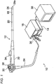
- FIG. 1 is a system configuration view of an entire electronic endoscopic apparatus according to an exemplary embodiment of the present invention.
- the electronic endoscopic apparatus (endoscope system) 10 of the present exemplary embodiment includes an endoscopic scope 12, and a processor device 14 and a light source device 16 that constitute a main body apparatus.
- the endoscopic scope 12 includes a flexible inserting unit 20 that is inserted into a body cavity of a patient (a subject), a manipulating unit 22 installed to be connected with a base end of the inserting unit 20, and a universal cord 24 that is connected with the processor device 14 and the light source device 16.
- a front-end part 26 is continuously formed in the front-end of the inserting unit 20, an imaging chip 54 (an imaging device see FIG. 3 ) for photographing the inside of the body cavity is accommodated in the front-end part 26.
- a curved unit 28 formed by connecting a plurality of curved pieces is installed in the rear of the front-end part 26.
- the curved unit 28 is curvedly operated in the up-down and left-right directions by pushing/pulling a wire provided by being inserted within the inserting unit 20 when an angle knob 30 installed in the manipulating unit 22 is manipulated. Therefore, the front-end part 26 faces a desired direction within the body cavity.
- a connector 36 is installed in the base end of the universal cord 24.
- the connector 36 is a complex type, and is connected to the light source device 16 as well as the processor device 14.
- the processor device 14 supplies power to the endoscopic scope 12 via a cable 68 (see FIG. 3 ) inserted through the universal cord 24 to control the driving of the imaging chip 54, and at the same time, the processor device 14 receives an imaging signal transmitted from the imaging chip 54 via the cable 68, and performs various signal processings on the received imaging signal to convert into image data.
- the image data converted in the processor device 14 is displayed in a monitor 38 as an endoscopic photographing image (an observation image).
- the monitor 38 is connected to the processor device 14 with a cable.
- the processor device 14 is also electrically connected to the light source device 16 via the connector 36, and generally controls the operations of the electronic endoscopic apparatus 10 including the light source device 16.
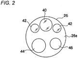
- FIG. 2 is a front view illustrating a front-end surface 26a of the front-end part 26 of the endoscopic scope 12. As illustrated in FIG. 2 , an observation window 40, illuminating windows 42, a forceps outlet 44, an air/water transferring nozzle 46 are formed in the front-end surface 26a of the front-end part 26.
- the observation window 40 is arranged at a center part of the front-end surface 26a and a position offset from the center of the front-end surface 26a.
- Two illuminating windows 42 are arranged in symmetric locations with respect to the observation window 40, and illuminate the light from the light source device 16 to the portion to be observed within the body cavity.
- the forceps outlet 44 is connected to a forceps channel 70 (See, FIG. 3 ) arranged within the inserting unit 20, and is communicated with a forceps inlet 34 (see FIG. 1 ) installed in the manipulating unit 22.
- Various treatment tools of which front-ends are provided with, for example, an injection needle or a high frequency mess, are inserted through the forceps inlet 34, and the front-ends of the various treatment tools come out from the forceps outlet 44 and into the body cavity.
- the air/water transferring nozzle 46 sprays cleaning water or air supplied from an air/water transferring device accommodated in the light source device 16 toward the inside of the body cavity or the observation window 40 according to the manipulation of an air/water transferring button 32 (see FIG. 1 ) installed in the manipulating unit 22.
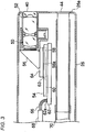
- FIG. 3 is a view illustrating the longitudinal cross-section of the front-end part 26 of the endoscopic scope 12.
- a barrel 52 is disposed inside the observation window 40.
- the barrel 52 holds an object optical system 50 to receive an image light of a portion to be observed within the body cavity.
- the barrel 52 is attached such that the optic axis of the object optical system 50 is parallel to the center axis of the inserting unit 20.
- a prism 56 is connected to the rear end of the barrel 52. The prism 56 guides a light such that the image light of the portion to be observed is bent through the object optical system 50 at right angles to be directed to the imaging chip 54.
- the imaging chip 54 is a monolithic semiconductor (a sensor chip) which is integrally formed with a solid-state imaging device 58 and a peripheral circuit 60 that performs the driving and the input/output of the signals of the solid-state imaging device 58.
- the imaging chip 54 is mounted on a support substrate 62.
- the imaging surface (light-receiving surface) 58a of the solid-state imaging device 58 is arranged to face an exit surface of the prism 56.
- a rectangular plate shaped cover glass 64 is attached on the imaging surface 58a via a rectangular frame shaped spacer 63.
- the imaging chip 54, the spacer 63 and the cover glass 64 are assembled using an adhesive, and as a result, the imaging surface 58a is protected from the infiltration of dust or the like.
- a plurality of input/output terminals 62a are installed side by side in the width direction in the rear end of the support substrate 62 installed to extend toward the rear end of the inserting unit 20.
- the input/output terminals 62a are connected to signal lines 66 to exchange various signals with the processor device 14 through the universal cord 24, and are electrically connected to the peripheral circuit 60 within the imaging chip 54 through, for example, wirings or bonding pads (not illustrated) formed in the support substrate 62.
- the signal lines 66 are integrally inserted within a flexible tubular cable 68.
- the cable 68 is inserted into the inside of each of the inserting unit 20, the manipulating unit 22 and the universal cord 24, and is connected to the connector 36.
- an illuminating unit is installed in the inner side of the illuminating windows 42.
- the exit end 120a of a light guide 120 (see FIG. 4 ) that guides the illuminating lights from the light source device 16 is disposed in the illuminating unit, and the exit end 120a is installed to face the illuminating windows 42.
- the light guide 120 is inserted into the inside of each of the inserting unit 20, the manipulating unit 22 and the universal cord 24, like the cable 68, and is connected to the connector 36 at the incident end thereof.
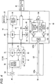
- FIG. 4 is a block diagram illustrating a control system of the electronic endoscopic apparatus 10.
- the imaging device 58 an analog signal processing circuit (an analog front end; AFE) 72, a timing generator (TG) 78, and a CPU 80 are installed in the front end part 26 of the endoscopic scope 12.
- the AFE 72 or the TG 78 corresponds to the peripheral circuit 60 in FIG. 3 .
- the CPU 80 is connected to a memory 81 such as, for example, an EEPROM.
- the vertical stripe correction data of the solid-state imaging device 58 is preserved in the memory 81.
- the TG 78 generates a driving pulse (for example, a vertical/horizontal scan pulse and a reset pulse) of the solid-state imaging device 58 and a synchronized pulse for the AFE 72, based on the control of the CPU 80.
- the solid-state imaging device 58 is driven according to the driving pulse inputted from the TG 78, and photoelectrically converts the optical shape imaged on the imaging surface 58a through the object optical system 50 to output as an imaging signal.
- a plurality of pixels are arranged in a matrix type in the imaging surface 58a of the solid-state imaging device 58, and a photo sensor (photoelectric conversion device) is installed in each of the pixels.
- the light incident to the imaging surface 58a of the solid-state imaging device 58 is accumulated in the photo sensor of each of the pixels as electrical charges.
- the signal electrical charges accumulated in the photo sensor of each of the pixels are sequentially read out as pixel signals and output in a predetermined frame rate by vertical and horizontal scanning using a vertical scan circuit and a horizontal scan circuit (both not illustrated).
- the solid-state imaging device 58 is a single-plate color imaging type solid-state imaging device including color filters (for example, primary color filters in a Bayer array) formed by a plurality of color segments.
- color filters for example, primary color filters in a Bayer array
- the configuration of the signal read-out circuit that reads out the accumulated charges of each of the photo sensors of the solid-state imaging device 58 as an imaging signal is known, and a general configuration such as, for example, a three transistor configuration or a four transistor configuration may be applied thereto. The descriptions thereof will be omitted herein.
- the AFE 72 is constituted by a correlated double sampling (CDS) circuit, an automatic gain circuit (AGC), and an A/D converter.
- the CDS circuit performs a correlated double sampling processing with respect to an imaging signal outputted from the solid-state imaging device 58 to remove an amp noise and a reset noise generated from the solid-state imaging device 58.
- the AFE 72 is provided for each of the columns of the solid-state imaging device 58.
- the AGC amplifies the imaging signal of which the noise is removed by the CDS circuit to a gain (amplifying rate) designated from the CPU 80.
- the A/D converter converts the imaging signal amplified by the AGC into a digital signal in a predetermined bit number, and outputs the converted signal.
- the imaging signal (digital imaging signal) digitalized and output from the AFE 72 is input to the processor device 14 via the signal lines 66.
- the processor device 14 is configured to include the CPU 82, a ROM 84, a RAM 85, an image processing circuit (DSP) 86, and a display control circuit 88.
- the CPU 82 controls each part of the processor device 14, and at the same time, generally controls the entire electronic endoscopic apparatus 10.
- Various programs to control the operations of the processor device 14 or control data are stored in advance in the ROM 84.
- programs executed by the CPU 82 or data are temporarily stored in the RAM 85.
- the DSP 86 performs, for example, a vertical stripe noise correction processing, a color interpolation, a color separation, a color balance adjustment, a gamma adjustment, and an image enhancement processing to generate an image data with respect to the imaging signal imputed from the AFE 72 based on the control of the CPU 82.
- the image data output from the DSP 86 is input to the display control circuit 88, and the display control circuit 88 converts the image data input from the DSP 86 into a signal format corresponding to the monitor 38 to be displayed to the screen of the monitor 38.
- the manipulating unit 90 of the processor device 14 is provided with a mode conversion button to select or convert the operation modes of the solid-state imaging device 58, or various buttons to receive other instruction inputs from user.
- the light source device 16 is configured to include a main light source 100, a main light source driving circuit 101, a special light source 102, a special light source driving circuit 103, a CPU 104, and a multiplexer unit 105.
- the CPU 104 communicates with the CPU 82 of the processor device 14 to control the main light source driving circuit 101 and the special light source driving circuit 103.
- the main light source 100 emits a white light
- the special light source 102 emits a special light of a narrow band of which the center is, for example, 420 nm.
- the white light or the special light exits to the incident end 120b of the light guide 120 through the multiplexer unit 105.
- the inserting unit 20 of the endoscopic scope 12 is inserted into the body cavity.
- a moving image in the inside of the body cavity captured by the solid-state imaging device 58 is observed through the monitor 38 while illuminating the inside of the body cavity using the illuminating light from the light source device 16.
- the DSP 86 receives captured image signals (an RAW signals) outputted from the solid-state imaging device 58 and performs vertical stripe correction for each of the colors. Then, the DSP 86 performs known various image processings such as, for example, a synchronization processing (de-mosaic processing), a gamma correction processing and an RGB/YC conversion processing to the captured image signals of each pixel position after the vertical stripe correction, thereby generating an image to be displayed on the monitor 38.
- a synchronization processing de-mosaic processing
- a gamma correction processing e.g., a gamma correction processing
- RGB/YC conversion processing RGB/YC conversion processing
- the vertical stripe correction data used when performing the vertical stripe correction is determined in the following manner, and is stored in the memory 81.
- FIG. 5 is a schematic view of a surface of the solid-state imaging device 58.
- Three primary color filters of R (red), G (green), and B (blue) are arranged in a Bayer array in the solid-state imaging device 58 in which a plurality of pixels are arranged in a square lattice array.
- a green (G) filter adjacent to a pixel equipped with an R filter in a transverse direction (row direction) is set to a "Gr”
- a green (G) filter adjacent to a pixel equipped with a B filter in the transverse direction is set to a "Gb".
- the Gr and Gb are the same in color, but are treated as having different colors when the vertical stripe correction data are calculated.
- each of the images is divided into color surfaces of four colors of R, Gr, Gb, and B, and an average value (total average value) of the pixel detection values of the entire area for each of the colors (R, Gr, Gb, B) is calculated.
- an average value (column average value) of the detection values of the individual pixels aligned in the same vertical direction (column direction) is calculated for each of the colors (R, Gr, Gb, B).
- a column average value - a total average value is calculated for each of the colors (R, Gr, Gb, B) and for each of the pixel columns.
- a data group of the "column average values - total average values” for each of the colors and for each of the pixel columns forms a profile of a vertical stripe strength.
- FIG. 8 is a graph illustrating a profile of the vertical stripe strength of, for example, Gr color.
- the transverse axis indicates a transverse position (column coordinate position) of the solid-state imaging device 58, and the vertical axis indicates the value of the vertical stripe strength.
- the removal of the vertical stripe noise may be performed, for example, as below.
- columns where Gr colors and B colors are aligned and columns where Gb colors and R colors are aligned are alternately arranged.
- a value of a Gr color which is calculated by subtracting the vertical stripe correction data for the Gr color at the pixel column position from a real Gr pixel detection value detected from the pixel column of Gr colors and B colors, is set to a Gr pixel detection value after the vertical stripe correction. The same calculation will be performed with respect to the B colors, Gb colors, and R colors.
- a vertical stripe may appear in sight in the observation image in an observation performed under a special environment, for example, such as an electronic endoscope. This is believed due to an effect of the quantization error by rounding off below the decimal point.
- FIG. 8 is a graph illustrating a vertical strip strength distribution after the vertical stripe correction of the captured image using the vertical stripe correction data of an integer. That is, it is a graph illustrating residue data after the correction by an integer part.
- the transverse axis is the coordinate of a pixel column position, and the vertical axis is the residue strength of a vertical stripe.
- the residue of a vertical stripe is within the range of -0.5 to +0.5.
- the amplitude of the residue strength of the vertical stripe may theoretically become "1" in its maximum. For this reason, the residue equal to or less than ⁇ 0.5 needs to be corrected to be smaller in order to perform the vertical stripe correction with higher precision.
- the vertical stripe correction data of a fractional part may be assigned to residue data after the residue data is corrected by the vertical stripe correction data of an integer, as illustrated in FIG. 9 .
- the assignment of the vertical stripe correction data of the fractional part is determined based on the following viewpoint of (a).
- the correction data of FIG. 9 are set forth as below.
- the correction data are set to eleven vertical stripe correction data: "0" when the residue data is “-0.05 to +0.05", “0.1” when the residue data is “0.05 to 0.15", “0.2” when the residue data is “0.15 to 0.25", “0.3” when the residue data is “0.25 to 0.35", “0.4” when the residue data is “0.35 to 0.45", “0.5” when the residue data is “0.45 to 0.5”, “-0.1” when the residue data is “-0.05 to -0.15", “-0.2” when the residue data is “-0.15 to -0.25", “-0.3” when the residue data is “-0.25 to -0.35", “-0.4” when the residue data is “-0.35 to -0.45", and “-0.5” when the residue data is “-0.45 to -0.5".
- how to assign the correction data of a fractional part for residue data is not limited to the example of FIG. 9 .
- FIG. 10 is an explanatory diagram of a correction method by correction data of a fractional part.
- the correction using the vertical stripe correction data of a fractional part is also performed after a captured image signal is converted into digital data by an A/D converter. For this reason, the correction of a portion below the decimal point cannot be performed as it is. That is, the addition and subtraction of, for example, "0.3” cannot be performed for a pixel detection value after the correction of the integer part. Therefore, for example, when the correction of "0.3” for Gr color in the pixel column thereof is performed, the Gr pixels belonging to the pixel column are subtracted by "1" in a ratio of three pixels to ten pixels. Therefore, it becomes equivalent to the case where the ten pixels are subtracted by "0.3” on average. In this way, the correction of each of " ⁇ 0.1", “ ⁇ 0.2”, “ ⁇ 0.3”, “ ⁇ 0.4” and " ⁇ 0.5” is performed as illustrated in FIG. 10 .
- Such correction is performed for every frame of a moving image. Pixels to be subtracted by the value "1" whenever frames are changed may be selected randomly using, for example, random numbers rather than being fixed. As a result of simulation, it was found out that the results are the same regardless of whether the pixels to be subtracted are fixed or randomly selected. However, it is believed that the correction through the random selection is more stable. The user may be allowed to select either method.
- FIG. 11 is a graph illustrating an effect by performing the correction of a fractional part.
- the characteristic graph I represents the effect when only the vertical stripe correction of an integer part was performed (as in FIG. 8 ), and the residue data of a vertical stripe of " ⁇ 0.5" remain.
- the characteristic graph II is a graph when the vertical stripe correction of an integer part and the vertical stripe correction of a fractional part are both performed.
- the residue data of a vertical stripe become equal to or less than " ⁇ 0.05" as illustrated in (a), so that the vertical stripe becomes noticeable.
- the vertical stripe correction data of an integer part is calculated for each of the colors by rounding off below the decimal point, and the vertical stripe correction data of a fractional part below the decimal point is calculated for each of the colors, so that the correction is performed using both data. Accordingly, even in an observation image under a special environment as an electronic endoscope, it is possible to make the visibility of the observation image good.
- the noise reduction processing may be jointly used in order to reduce a noise component other than the vertical stripe noise.
- the present invention may be applied to the vertical stripe correction of an image captured by a CMOS type or CCD type imaging device mounted in, for example, a general digital camera and a video camera. Further, of course, the above-described exemplary embodiments may be applied to a transverse stripe noise.
- the stripe noise correction method of a captured image includes: capturing, by a single-plate type image sensor for color image capturing that includes a plurality of pixels arranged in a square lattice array and a plurality of color filters with different colors which are respectively stacked on each of the pixels in a mosaic type, a plurality of images each of which has the same color with one of the colors of the color filters; calculating an average image for color images for the plurality of images and dividing the captured image signals of the average image into individual colors of the color filters; calculating, for each color, the stripe noise value for each pixel column or each pixel row by subtracting the average value of the captured image signals in the entire area where the pixels of the image sensor are arranged from the average value of the captured image signals of each pixel column or each pixel row of the image sensor; storing a value calculated by rounding off a portion below the decimal point of the stripe noise value into a memory as correction data of an integer part that corrects the stripe
- the stripe noise correction method of the captured image of the exemplary embodiment when the magnitude of the quantization error which is rounded off below the decimal point is n/m where m and n are positive integers and m>n, the values of n pixels among m pixels of the pixel column or the pixel row are subtracted by "1" and the values of the remaining (m-n) pixels are not subtracted to perform the correction based on the correction data of the fractional part.
- a photographing apparatus of the exemplary embodiment includes: the image sensor set forth in any one as described above; the memory set forth in any one as described above; and an image processing unit that performs the stripe noise correction set forth in any one as described.
- An electronic endoscopic apparatus of the exemplary embodiment includes: an endoscopic scope that is inserted into a body cavity; the image sensor that is accommodated in the front end part of the endoscopic scope and set forth in any one as described above; an illuminating unit that illuminates illuminating light from the front end part of the endoscopic scope; the memory set forth in any one as described above; and an image processing unit that performs the stripe noise correction set forth in any one as described above.
- the illuminating unit illuminates a special light of a narrow band as the illuminating light.
- the stripe noise may be removed with high precision, and thus a high quality of captured image may be obtained.
- the stripe noise correction method may correct the stripe noise of the captued image in a high precision, and may be effectualy applid to, for example, a digital camera, a digital video camera, a handheld phone with a camera, an electronic equimpment with a camera, and an electronic endoscope.
Landscapes
- Engineering & Computer Science (AREA)
- Multimedia (AREA)
- Signal Processing (AREA)
- Endoscopes (AREA)
- Instruments For Viewing The Inside Of Hollow Bodies (AREA)
- Transforming Light Signals Into Electric Signals (AREA)
- Closed-Circuit Television Systems (AREA)
Claims (6)
- Streifenrauschen-Korrekturverfahren für ein aufgenommenes Bild, umfassend:mit Hilfe eines Einzelplatten-Bildsensors (54, 58) für Farbbildaufnahmen, der mehrere in einem quadratischen Gitterfeld angeordnete Pixel und mehrere Farbfilter unterschiedlicher Farben, die auf jedem der Pixel mosaikartig aufgebracht sind, enthält, werden mehrere Bilder (Gr, Gb, R, B) aufgenommen, von denen jedes die gleiche Farbe von einer der Farben der Farbfilter besitzt;es wird ein Durchschnittsbild für Farbbilder für die mehreren Bilder (Gr, Gb, R, B) berechnet, und die aufgenommenen Bildsignale des Durchschnittsbilds werden unterteilt in individuelle Farben der Farbfilter;für jede Farbe wird der Streifenrauschenwert für jede Pixelspalte oder jede Pixelreihe berechnet, indem der Durchschnittswert der aufgenommenen Bildsignale in der gesamten Fläche, in der die Pixel des Bildsensors angeordnet sind, subtrahiert wird von dem Durchschnittswert der aufgenommenen Bildsignale jeder Pixelspalte oder jeder Pixelreihe des Pixelsensors (54, 85);Speichern eines Werts, der berechnet wird durch Abrunden eines Teils unterhalb des Dezimalpunkts des Streifenrauschenwerts, in einem Speicher (85) als Korrekturdaten eines ganzzahligen Teils, welcher das Streifenrauschen für jede Farbe korrigiert; und Speichern des Betrags eines Quantisierungsfehlers, der berechnet wird durch Abrunden für jede Farbe und für jede Pixelspalte oder jede Pixelreihe, in dem Speicher als Korrekturdaten für einen Bruchteil; undKorrigieren der aufgenommenen Bildsignale des von dem Bildsensor aufgenommenen Bilds mit den Korrekturdaten für den ganzzahligen Teil und den Bruchteil, die aus dem Speicher (85) ausgelesen werden.
- Streifenrauschen-Korrekturverfahren, bei dem,
wenn der abgerundete Betrag des Quantisierungsfehlers unterhalb des Dezimalpunkts n/m beträgt, mit m und n als natürliche Zahlen und m>n, die Werte von n Pixeln unter m Pixeln der Pixelspalte oder der Pixelreihe um "1" vermindert werden, und die Werte der übrigen (m-n) Pixel nicht vermindert werden, um die Korrektur basierend auf den Korrekturdaten des Bruchteils auszuführen. - Streifen-Korrekturverfahren nach Anspruch 2, bei dem
für jedes Einzelbild des aufgenommenen Bewegunsbilds die Art und Weise, wie die n Pixel unter den m Pixeln ausgewählt werden, auf Zufallsbasis geändert wird. - Fotoaufnahmevorrichtung (10), umfassend:einen Bildsensor (54, 58) und einen Speicher (85) zum Speichern der Korrekturdaten gemäß Anspruch 1; undeine Bildverarbeitungseinheit, ausgebildet zum Ausführen des Streifenrauschen-Korrekturverfahrens nach einem der Ansprüche 1 bis 3.
- Vorrichtung nach Anspruch 4, ausgebildet als elektronische Endoskopvorrichtung (10), umfassend:ein Endoskop (12), ausgebildet zum Einführen in einen Körperhohlraum, wobei der Bildsensor in einem vorderen Endteil (26) des Endoskops (12) aufgenommen ist, und eine Beleuchtungseinheit (16) vorgesehen ist, ausgebildet zum Aussenden von Beleuchtungslicht aus dem vorderen Endteil des Endoskops.
- Vorrichtung nach Anspruch 5, bei der neue Teile die Beleuchtungseinheit (16) ausgebildet ist zum Emittieren von Speziallicht eines schmalen Bands als das Beleuchtungslicht.
Applications Claiming Priority (1)
| Application Number | Priority Date | Filing Date | Title |
|---|---|---|---|
| JP2012080680A JP5648010B2 (ja) | 2012-03-30 | 2012-03-30 | 機器の作動方法及び撮影装置と電子内視鏡装置 |
Publications (3)
| Publication Number | Publication Date |
|---|---|
| EP2645708A2 EP2645708A2 (de) | 2013-10-02 |
| EP2645708A3 EP2645708A3 (de) | 2017-02-22 |
| EP2645708B1 true EP2645708B1 (de) | 2018-01-10 |
Family
ID=48092696
Family Applications (1)
| Application Number | Title | Priority Date | Filing Date |
|---|---|---|---|
| EP13161706.0A Not-in-force EP2645708B1 (de) | 2012-03-30 | 2013-03-28 | Verfahren zur Korrektur von streifenartigem Rauschen eines aufgenommenen Bildes, Photographiervorrichtung und elektronische Endoskopvorrichtung |
Country Status (3)
| Country | Link |
|---|---|
| US (1) | US9282302B2 (de) |
| EP (1) | EP2645708B1 (de) |
| JP (1) | JP5648010B2 (de) |
Families Citing this family (13)
| Publication number | Priority date | Publication date | Assignee | Title |
|---|---|---|---|---|
| CN103679648B (zh) * | 2013-11-18 | 2016-07-27 | 北京空间机电研究所 | 一种基于空间分割的矩匹配卫星影像条带噪声去除方法 |
| JP6196900B2 (ja) * | 2013-12-18 | 2017-09-13 | オリンパス株式会社 | 内視鏡装置 |
| JP6230409B2 (ja) * | 2013-12-20 | 2017-11-15 | オリンパス株式会社 | 内視鏡装置 |
| WO2015093295A1 (ja) * | 2013-12-20 | 2015-06-25 | オリンパス株式会社 | 内視鏡装置 |
| CN106127705A (zh) * | 2016-06-22 | 2016-11-16 | 成都市晶林科技有限公司 | 红外图像去横条纹处理方法 |
| CN106815820B (zh) * | 2017-01-24 | 2019-09-10 | 西安科技大学 | 一种红外图像条状噪声消除方法 |
| JP6832250B2 (ja) * | 2017-07-18 | 2021-02-24 | オリンパス株式会社 | 内視鏡、制御装置、補正方法およびプログラム |
| CN110910324B (zh) * | 2019-11-19 | 2023-04-14 | 山东神戎电子股份有限公司 | 红外视频的去竖条纹方法 |
| CN111028179B (zh) * | 2019-12-20 | 2023-04-28 | 浙江大华技术股份有限公司 | 一种条纹校正方法、装置、电子设备及存储介质 |
| CN112565637B (zh) * | 2020-11-20 | 2022-07-29 | 中国航空工业集团公司洛阳电光设备研究所 | 一种单色sCMOS摄像机中低照度下条带噪声的去除方法 |
| CN113465544B (zh) * | 2021-06-25 | 2022-04-08 | 安徽农业大学 | 一种条纹投影三维测量非线性误差校正方法 |
| CN116055902B (zh) * | 2022-12-30 | 2024-11-22 | 深圳锐视智芯科技有限公司 | 一种图像生成方法、装置、图像传感器及存储介质 |
| CN121101392A (zh) * | 2025-11-14 | 2025-12-12 | 杭州巨星科技股份有限公司 | 吸尘器 |
Family Cites Families (18)
| Publication number | Priority date | Publication date | Assignee | Title |
|---|---|---|---|---|
| CA1194987A (en) * | 1981-09-30 | 1985-10-08 | Yasuo Takemura | Solid-state color television camera |
| DE3482366D1 (de) * | 1983-07-21 | 1990-06-28 | Victor Company Of Japan | Farbfernsehkamera mit zwei oder mehr festkoerper-bildaufnahme-einrichtungen. |
| JP2000137172A (ja) * | 1998-10-29 | 2000-05-16 | Olympus Optical Co Ltd | 撮像装置 |
| JP4107029B2 (ja) * | 2002-09-20 | 2008-06-25 | 富士ゼロックス株式会社 | 画像読取装置 |
| JP3972302B2 (ja) * | 2003-03-26 | 2007-09-05 | ソニー株式会社 | 撮像素子 |
| JP4379006B2 (ja) * | 2003-06-04 | 2009-12-09 | 株式会社ニコン | 撮像装置 |
| JP4340503B2 (ja) * | 2003-09-18 | 2009-10-07 | 株式会社リコー | 原稿読取装置 |
| JP4144517B2 (ja) | 2003-12-05 | 2008-09-03 | ソニー株式会社 | 固体撮像装置、撮像方法 |
| JP4027340B2 (ja) * | 2004-04-20 | 2007-12-26 | キヤノン株式会社 | 撮像装置及び撮像方法 |
| JP4661168B2 (ja) * | 2004-11-02 | 2011-03-30 | ソニー株式会社 | 固体撮像素子の信号処理装置及び方法並びに撮像装置 |
| JP4341528B2 (ja) * | 2004-11-02 | 2009-10-07 | ソニー株式会社 | 固体撮像素子の信号処理装置及び方法並びに撮像装置 |
| US7456384B2 (en) * | 2004-12-10 | 2008-11-25 | Sony Corporation | Method and apparatus for acquiring physical information, method for manufacturing semiconductor device including array of plurality of unit components for detecting physical quantity distribution, light-receiving device and manufacturing method therefor, and solid-state imaging device and manufacturing method therefor |
| JP2007053691A (ja) * | 2005-08-19 | 2007-03-01 | Micron Technol Inc | サブlsbを用いた拡張デジタルデータ路構造 |
| EP2007131B1 (de) * | 2006-04-07 | 2013-02-27 | Mitsubishi Electric Corporation | Rauschbeseitigungsvorrichtung und rauschbeseitigungsverfahren |
| JP4238900B2 (ja) * | 2006-08-31 | 2009-03-18 | ソニー株式会社 | 固体撮像装置、撮像装置 |
| JP4396757B2 (ja) | 2007-10-22 | 2010-01-13 | ソニー株式会社 | ノイズ補正回路、撮像装置及びノイズ補正方法 |
| JP5124492B2 (ja) * | 2009-01-08 | 2013-01-23 | Hoya株式会社 | 固定パターンノイズ除去ユニット、撮像ユニット、および電子内視鏡システム |
| CN102984989B (zh) * | 2010-08-30 | 2015-08-19 | 奥林巴斯医疗株式会社 | 内窥镜装置 |
-
2012
- 2012-03-30 JP JP2012080680A patent/JP5648010B2/ja active Active
-
2013
- 2013-03-28 EP EP13161706.0A patent/EP2645708B1/de not_active Not-in-force
- 2013-03-29 US US13/853,696 patent/US9282302B2/en active Active
Non-Patent Citations (1)
| Title |
|---|
| None * |
Also Published As
| Publication number | Publication date |
|---|---|
| JP2013208284A (ja) | 2013-10-10 |
| EP2645708A3 (de) | 2017-02-22 |
| JP5648010B2 (ja) | 2015-01-07 |
| EP2645708A2 (de) | 2013-10-02 |
| US9282302B2 (en) | 2016-03-08 |
| US20130258082A1 (en) | 2013-10-03 |
Similar Documents
| Publication | Publication Date | Title |
|---|---|---|
| EP2645708B1 (de) | Verfahren zur Korrektur von streifenartigem Rauschen eines aufgenommenen Bildes, Photographiervorrichtung und elektronische Endoskopvorrichtung | |
| JP5245022B1 (ja) | 撮像装置 | |
| CN102740760B (zh) | 内窥镜装置 | |
| JP5847017B2 (ja) | 電子内視鏡装置及びその作動方法 | |
| US20100277625A1 (en) | Image processing apparatus, imaging apparatus, method of correction coefficient calculation, and storage medium storing image processing program | |
| JP2011205348A (ja) | 固体撮像装置および画像記録装置 | |
| US10602919B2 (en) | Imaging device | |
| WO2015146318A1 (ja) | 内視鏡システム、内視鏡システムのプロセッサ装置、及び内視鏡システムの作動方法 | |
| US10441149B2 (en) | Imaging device, endoscope, and endoscope system | |
| JP2012143319A (ja) | 内視鏡システム及びその駆動方法 | |
| JP2012217486A (ja) | 内視鏡システム及びその駆動方法 | |
| US9113045B2 (en) | Electronic endoscopic apparatus and control method thereof | |
| JP2004229055A (ja) | 画像処理装置 | |
| WO2015146972A1 (ja) | 内視鏡システム、内視鏡システムのプロセッサ装置、及び内視鏡システムの作動方法 | |
| JP5734060B2 (ja) | 内視鏡システム及びその駆動方法 | |
| JP5827868B2 (ja) | 電子内視鏡及び固定パターンノイズ除去方法 | |
| WO2019123600A1 (ja) | 撮像装置 | |
| JP2013126002A (ja) | 内視鏡装置 | |
| JP2010239192A (ja) | 固体撮像素子及び撮像装置及び画像信号処理方法 | |
| KR20160085340A (ko) | 화상 처리 장치 | |
| JP6277138B2 (ja) | 内視鏡システム及びその作動方法 | |
| JP5156560B2 (ja) | 電子内視鏡システム | |
| JP6589071B2 (ja) | 撮像装置、内視鏡および内視鏡システム | |
| JP6312254B2 (ja) | 内視鏡システム及びその作動方法 | |
| JP6005794B2 (ja) | 内視鏡システム及びその駆動方法 |
Legal Events
| Date | Code | Title | Description |
|---|---|---|---|
| PUAI | Public reference made under article 153(3) epc to a published international application that has entered the european phase |
Free format text: ORIGINAL CODE: 0009012 |
|
| AK | Designated contracting states |
Kind code of ref document: A2 Designated state(s): AL AT BE BG CH CY CZ DE DK EE ES FI FR GB GR HR HU IE IS IT LI LT LU LV MC MK MT NL NO PL PT RO RS SE SI SK SM TR |
|
| AX | Request for extension of the european patent |
Extension state: BA ME |
|
| PUAL | Search report despatched |
Free format text: ORIGINAL CODE: 0009013 |
|
| AK | Designated contracting states |
Kind code of ref document: A3 Designated state(s): AL AT BE BG CH CY CZ DE DK EE ES FI FR GB GR HR HU IE IS IT LI LT LU LV MC MK MT NL NO PL PT RO RS SE SI SK SM TR |
|
| AX | Request for extension of the european patent |
Extension state: BA ME |
|
| RIC1 | Information provided on ipc code assigned before grant |
Ipc: H04N 5/335 20110101AFI20170119BHEP Ipc: H04N 5/225 20060101ALN20170119BHEP Ipc: H04N 5/365 20110101ALI20170119BHEP |
|
| STAA | Information on the status of an ep patent application or granted ep patent |
Free format text: STATUS: REQUEST FOR EXAMINATION WAS MADE |
|
| 17P | Request for examination filed |
Effective date: 20170518 |
|
| RBV | Designated contracting states (corrected) |
Designated state(s): AL AT BE BG CH CY CZ DE DK EE ES FI FR GB GR HR HU IE IS IT LI LT LU LV MC MK MT NL NO PL PT RO RS SE SI SK SM TR |
|
| GRAP | Despatch of communication of intention to grant a patent |
Free format text: ORIGINAL CODE: EPIDOSNIGR1 |
|
| STAA | Information on the status of an ep patent application or granted ep patent |
Free format text: STATUS: GRANT OF PATENT IS INTENDED |
|
| RIC1 | Information provided on ipc code assigned before grant |
Ipc: H04N 5/225 20060101ALN20170719BHEP Ipc: H04N 9/64 20060101ALI20170719BHEP Ipc: H04N 5/335 20110101AFI20170719BHEP Ipc: H04N 5/365 20110101ALI20170719BHEP |
|
| INTG | Intention to grant announced |
Effective date: 20170811 |
|
| GRAS | Grant fee paid |
Free format text: ORIGINAL CODE: EPIDOSNIGR3 |
|
| GRAA | (expected) grant |
Free format text: ORIGINAL CODE: 0009210 |
|
| STAA | Information on the status of an ep patent application or granted ep patent |
Free format text: STATUS: THE PATENT HAS BEEN GRANTED |
|
| AK | Designated contracting states |
Kind code of ref document: B1 Designated state(s): AL AT BE BG CH CY CZ DE DK EE ES FI FR GB GR HR HU IE IS IT LI LT LU LV MC MK MT NL NO PL PT RO RS SE SI SK SM TR |
|
| REG | Reference to a national code |
Ref country code: CH Ref legal event code: EP Ref country code: AT Ref legal event code: REF Ref document number: 963639 Country of ref document: AT Kind code of ref document: T Effective date: 20180115 |
|
| REG | Reference to a national code |
Ref country code: IE Ref legal event code: FG4D |
|
| REG | Reference to a national code |
Ref country code: DE Ref legal event code: R096 Ref document number: 602013031870 Country of ref document: DE |
|
| REG | Reference to a national code |
Ref country code: FR Ref legal event code: PLFP Year of fee payment: 6 |
|
| REG | Reference to a national code |
Ref country code: NL Ref legal event code: MP Effective date: 20180110 |
|
| REG | Reference to a national code |
Ref country code: AT Ref legal event code: MK05 Ref document number: 963639 Country of ref document: AT Kind code of ref document: T Effective date: 20180110 |
|
| PG25 | Lapsed in a contracting state [announced via postgrant information from national office to epo] |
Ref country code: NL Free format text: LAPSE BECAUSE OF FAILURE TO SUBMIT A TRANSLATION OF THE DESCRIPTION OR TO PAY THE FEE WITHIN THE PRESCRIBED TIME-LIMIT Effective date: 20180110 |
|
| PG25 | Lapsed in a contracting state [announced via postgrant information from national office to epo] |
Ref country code: LT Free format text: LAPSE BECAUSE OF FAILURE TO SUBMIT A TRANSLATION OF THE DESCRIPTION OR TO PAY THE FEE WITHIN THE PRESCRIBED TIME-LIMIT Effective date: 20180110 Ref country code: ES Free format text: LAPSE BECAUSE OF FAILURE TO SUBMIT A TRANSLATION OF THE DESCRIPTION OR TO PAY THE FEE WITHIN THE PRESCRIBED TIME-LIMIT Effective date: 20180110 Ref country code: NO Free format text: LAPSE BECAUSE OF FAILURE TO SUBMIT A TRANSLATION OF THE DESCRIPTION OR TO PAY THE FEE WITHIN THE PRESCRIBED TIME-LIMIT Effective date: 20180410 Ref country code: HR Free format text: LAPSE BECAUSE OF FAILURE TO SUBMIT A TRANSLATION OF THE DESCRIPTION OR TO PAY THE FEE WITHIN THE PRESCRIBED TIME-LIMIT Effective date: 20180110 Ref country code: FI Free format text: LAPSE BECAUSE OF FAILURE TO SUBMIT A TRANSLATION OF THE DESCRIPTION OR TO PAY THE FEE WITHIN THE PRESCRIBED TIME-LIMIT Effective date: 20180110 Ref country code: CY Free format text: LAPSE BECAUSE OF FAILURE TO SUBMIT A TRANSLATION OF THE DESCRIPTION OR TO PAY THE FEE WITHIN THE PRESCRIBED TIME-LIMIT Effective date: 20180110 |
|
| PG25 | Lapsed in a contracting state [announced via postgrant information from national office to epo] |
Ref country code: LV Free format text: LAPSE BECAUSE OF FAILURE TO SUBMIT A TRANSLATION OF THE DESCRIPTION OR TO PAY THE FEE WITHIN THE PRESCRIBED TIME-LIMIT Effective date: 20180110 Ref country code: SE Free format text: LAPSE BECAUSE OF FAILURE TO SUBMIT A TRANSLATION OF THE DESCRIPTION OR TO PAY THE FEE WITHIN THE PRESCRIBED TIME-LIMIT Effective date: 20180110 Ref country code: GR Free format text: LAPSE BECAUSE OF FAILURE TO SUBMIT A TRANSLATION OF THE DESCRIPTION OR TO PAY THE FEE WITHIN THE PRESCRIBED TIME-LIMIT Effective date: 20180411 Ref country code: PL Free format text: LAPSE BECAUSE OF FAILURE TO SUBMIT A TRANSLATION OF THE DESCRIPTION OR TO PAY THE FEE WITHIN THE PRESCRIBED TIME-LIMIT Effective date: 20180110 Ref country code: IS Free format text: LAPSE BECAUSE OF FAILURE TO SUBMIT A TRANSLATION OF THE DESCRIPTION OR TO PAY THE FEE WITHIN THE PRESCRIBED TIME-LIMIT Effective date: 20180510 Ref country code: BG Free format text: LAPSE BECAUSE OF FAILURE TO SUBMIT A TRANSLATION OF THE DESCRIPTION OR TO PAY THE FEE WITHIN THE PRESCRIBED TIME-LIMIT Effective date: 20180410 Ref country code: RS Free format text: LAPSE BECAUSE OF FAILURE TO SUBMIT A TRANSLATION OF THE DESCRIPTION OR TO PAY THE FEE WITHIN THE PRESCRIBED TIME-LIMIT Effective date: 20180110 Ref country code: AT Free format text: LAPSE BECAUSE OF FAILURE TO SUBMIT A TRANSLATION OF THE DESCRIPTION OR TO PAY THE FEE WITHIN THE PRESCRIBED TIME-LIMIT Effective date: 20180110 |
|
| REG | Reference to a national code |
Ref country code: DE Ref legal event code: R097 Ref document number: 602013031870 Country of ref document: DE |
|
| PG25 | Lapsed in a contracting state [announced via postgrant information from national office to epo] |
Ref country code: AL Free format text: LAPSE BECAUSE OF FAILURE TO SUBMIT A TRANSLATION OF THE DESCRIPTION OR TO PAY THE FEE WITHIN THE PRESCRIBED TIME-LIMIT Effective date: 20180110 Ref country code: IT Free format text: LAPSE BECAUSE OF FAILURE TO SUBMIT A TRANSLATION OF THE DESCRIPTION OR TO PAY THE FEE WITHIN THE PRESCRIBED TIME-LIMIT Effective date: 20180110 Ref country code: EE Free format text: LAPSE BECAUSE OF FAILURE TO SUBMIT A TRANSLATION OF THE DESCRIPTION OR TO PAY THE FEE WITHIN THE PRESCRIBED TIME-LIMIT Effective date: 20180110 Ref country code: RO Free format text: LAPSE BECAUSE OF FAILURE TO SUBMIT A TRANSLATION OF THE DESCRIPTION OR TO PAY THE FEE WITHIN THE PRESCRIBED TIME-LIMIT Effective date: 20180110 |
|
| REG | Reference to a national code |
Ref country code: CH Ref legal event code: PL |
|
| PLBE | No opposition filed within time limit |
Free format text: ORIGINAL CODE: 0009261 |
|
| STAA | Information on the status of an ep patent application or granted ep patent |
Free format text: STATUS: NO OPPOSITION FILED WITHIN TIME LIMIT |
|
| PG25 | Lapsed in a contracting state [announced via postgrant information from national office to epo] |
Ref country code: SK Free format text: LAPSE BECAUSE OF FAILURE TO SUBMIT A TRANSLATION OF THE DESCRIPTION OR TO PAY THE FEE WITHIN THE PRESCRIBED TIME-LIMIT Effective date: 20180110 Ref country code: SM Free format text: LAPSE BECAUSE OF FAILURE TO SUBMIT A TRANSLATION OF THE DESCRIPTION OR TO PAY THE FEE WITHIN THE PRESCRIBED TIME-LIMIT Effective date: 20180110 Ref country code: CZ Free format text: LAPSE BECAUSE OF FAILURE TO SUBMIT A TRANSLATION OF THE DESCRIPTION OR TO PAY THE FEE WITHIN THE PRESCRIBED TIME-LIMIT Effective date: 20180110 Ref country code: MC Free format text: LAPSE BECAUSE OF FAILURE TO SUBMIT A TRANSLATION OF THE DESCRIPTION OR TO PAY THE FEE WITHIN THE PRESCRIBED TIME-LIMIT Effective date: 20180110 Ref country code: DK Free format text: LAPSE BECAUSE OF FAILURE TO SUBMIT A TRANSLATION OF THE DESCRIPTION OR TO PAY THE FEE WITHIN THE PRESCRIBED TIME-LIMIT Effective date: 20180110 |
|
| REG | Reference to a national code |
Ref country code: BE Ref legal event code: MM Effective date: 20180331 |
|
| 26N | No opposition filed |
Effective date: 20181011 |
|
| REG | Reference to a national code |
Ref country code: IE Ref legal event code: MM4A |
|
| PG25 | Lapsed in a contracting state [announced via postgrant information from national office to epo] |
Ref country code: LU Free format text: LAPSE BECAUSE OF NON-PAYMENT OF DUE FEES Effective date: 20180328 |
|
| PG25 | Lapsed in a contracting state [announced via postgrant information from national office to epo] |
Ref country code: IE Free format text: LAPSE BECAUSE OF NON-PAYMENT OF DUE FEES Effective date: 20180328 |
|
| PG25 | Lapsed in a contracting state [announced via postgrant information from national office to epo] |
Ref country code: CH Free format text: LAPSE BECAUSE OF NON-PAYMENT OF DUE FEES Effective date: 20180331 Ref country code: BE Free format text: LAPSE BECAUSE OF NON-PAYMENT OF DUE FEES Effective date: 20180331 Ref country code: SI Free format text: LAPSE BECAUSE OF FAILURE TO SUBMIT A TRANSLATION OF THE DESCRIPTION OR TO PAY THE FEE WITHIN THE PRESCRIBED TIME-LIMIT Effective date: 20180110 Ref country code: LI Free format text: LAPSE BECAUSE OF NON-PAYMENT OF DUE FEES Effective date: 20180331 |
|
| PGFP | Annual fee paid to national office [announced via postgrant information from national office to epo] |
Ref country code: GB Payment date: 20190327 Year of fee payment: 7 |
|
| PG25 | Lapsed in a contracting state [announced via postgrant information from national office to epo] |
Ref country code: MT Free format text: LAPSE BECAUSE OF NON-PAYMENT OF DUE FEES Effective date: 20180328 |
|
| PG25 | Lapsed in a contracting state [announced via postgrant information from national office to epo] |
Ref country code: TR Free format text: LAPSE BECAUSE OF FAILURE TO SUBMIT A TRANSLATION OF THE DESCRIPTION OR TO PAY THE FEE WITHIN THE PRESCRIBED TIME-LIMIT Effective date: 20180110 |
|
| PG25 | Lapsed in a contracting state [announced via postgrant information from national office to epo] |
Ref country code: PT Free format text: LAPSE BECAUSE OF FAILURE TO SUBMIT A TRANSLATION OF THE DESCRIPTION OR TO PAY THE FEE WITHIN THE PRESCRIBED TIME-LIMIT Effective date: 20180110 Ref country code: HU Free format text: LAPSE BECAUSE OF FAILURE TO SUBMIT A TRANSLATION OF THE DESCRIPTION OR TO PAY THE FEE WITHIN THE PRESCRIBED TIME-LIMIT; INVALID AB INITIO Effective date: 20130328 |
|
| PG25 | Lapsed in a contracting state [announced via postgrant information from national office to epo] |
Ref country code: MK Free format text: LAPSE BECAUSE OF NON-PAYMENT OF DUE FEES Effective date: 20180110 |
|
| PGFP | Annual fee paid to national office [announced via postgrant information from national office to epo] |
Ref country code: FR Payment date: 20200214 Year of fee payment: 8 |
|
| GBPC | Gb: european patent ceased through non-payment of renewal fee |
Effective date: 20200328 |
|
| PG25 | Lapsed in a contracting state [announced via postgrant information from national office to epo] |
Ref country code: GB Free format text: LAPSE BECAUSE OF NON-PAYMENT OF DUE FEES Effective date: 20200328 |
|
| PG25 | Lapsed in a contracting state [announced via postgrant information from national office to epo] |
Ref country code: FR Free format text: LAPSE BECAUSE OF NON-PAYMENT OF DUE FEES Effective date: 20210331 |
|
| REG | Reference to a national code |
Ref country code: DE Ref legal event code: R079 Ref document number: 602013031870 Country of ref document: DE Free format text: PREVIOUS MAIN CLASS: H04N0005335000 Ipc: H04N0025000000 |
|
| P01 | Opt-out of the competence of the unified patent court (upc) registered |
Effective date: 20230515 |
|
| PGFP | Annual fee paid to national office [announced via postgrant information from national office to epo] |
Ref country code: DE Payment date: 20240130 Year of fee payment: 12 |
|
| REG | Reference to a national code |
Ref country code: DE Ref legal event code: R119 Ref document number: 602013031870 Country of ref document: DE |
|
| PG25 | Lapsed in a contracting state [announced via postgrant information from national office to epo] |
Ref country code: DE Free format text: LAPSE BECAUSE OF NON-PAYMENT OF DUE FEES Effective date: 20251001 |