EP2644367A1 - Strip, method for producing same, and method for producing pneumatic tire - Google Patents
Strip, method for producing same, and method for producing pneumatic tire Download PDFInfo
- Publication number
- EP2644367A1 EP2644367A1 EP11847081.4A EP11847081A EP2644367A1 EP 2644367 A1 EP2644367 A1 EP 2644367A1 EP 11847081 A EP11847081 A EP 11847081A EP 2644367 A1 EP2644367 A1 EP 2644367A1
- Authority
- EP
- European Patent Office
- Prior art keywords
- strip
- tire
- layer
- thickness
- core body
- Prior art date
- Legal status (The legal status is an assumption and is not a legal conclusion. Google has not performed a legal analysis and makes no representation as to the accuracy of the status listed.)
- Granted
Links
- 238000004519 manufacturing process Methods 0.000 title claims description 47
- 239000010410 layer Substances 0.000 claims abstract description 197
- 239000000203 mixture Substances 0.000 claims abstract description 76
- 229920001971 elastomer Polymers 0.000 claims abstract description 59
- 239000005060 rubber Substances 0.000 claims abstract description 54
- 229920002725 thermoplastic elastomer Polymers 0.000 claims abstract description 33
- 244000043261 Hevea brasiliensis Species 0.000 claims abstract description 9
- 229920003052 natural elastomer Polymers 0.000 claims abstract description 9
- 229920001194 natural rubber Polymers 0.000 claims abstract description 9
- UHKPXKGJFOKCGG-UHFFFAOYSA-N 2-methylprop-1-ene;styrene Chemical compound CC(C)=C.C=CC1=CC=CC=C1.C=CC1=CC=CC=C1 UHKPXKGJFOKCGG-UHFFFAOYSA-N 0.000 claims abstract description 8
- 239000002356 single layer Substances 0.000 claims abstract description 8
- 125000000484 butyl group Chemical group [H]C([*])([H])C([H])([H])C([H])([H])C([H])([H])[H] 0.000 claims abstract description 6
- 239000002131 composite material Substances 0.000 claims abstract description 6
- 229920006132 styrene block copolymer Polymers 0.000 claims abstract description 6
- 238000004073 vulcanization Methods 0.000 claims description 64
- 229920005995 polystyrene-polyisobutylene Polymers 0.000 claims description 45
- 238000000034 method Methods 0.000 claims description 41
- 238000000465 moulding Methods 0.000 claims description 41
- 229920000346 polystyrene-polyisoprene block-polystyrene Polymers 0.000 claims description 39
- 238000001125 extrusion Methods 0.000 claims description 33
- 238000010438 heat treatment Methods 0.000 claims description 3
- 238000012546 transfer Methods 0.000 claims description 2
- 230000001070 adhesive effect Effects 0.000 abstract description 18
- 238000009472 formulation Methods 0.000 description 44
- 229920000642 polymer Polymers 0.000 description 27
- 239000011324 bead Substances 0.000 description 25
- 230000000052 comparative effect Effects 0.000 description 23
- PPBRXRYQALVLMV-UHFFFAOYSA-N Styrene Chemical compound C=CC1=CC=CC=C1 PPBRXRYQALVLMV-UHFFFAOYSA-N 0.000 description 20
- 229920005989 resin Polymers 0.000 description 18
- 239000011347 resin Substances 0.000 description 18
- 238000004804 winding Methods 0.000 description 17
- 230000003247 decreasing effect Effects 0.000 description 12
- 230000035699 permeability Effects 0.000 description 12
- 239000000126 substance Substances 0.000 description 12
- 229920005549 butyl rubber Polymers 0.000 description 10
- 239000003208 petroleum Substances 0.000 description 10
- 238000006116 polymerization reaction Methods 0.000 description 10
- OKKJLVBELUTLKV-UHFFFAOYSA-N Methanol Chemical compound OC OKKJLVBELUTLKV-UHFFFAOYSA-N 0.000 description 9
- 229920005992 thermoplastic resin Polymers 0.000 description 9
- 239000013585 weight reducing agent Substances 0.000 description 9
- XLOMVQKBTHCTTD-UHFFFAOYSA-N Zinc monoxide Chemical compound [Zn]=O XLOMVQKBTHCTTD-UHFFFAOYSA-N 0.000 description 8
- VQTUBCCKSQIDNK-UHFFFAOYSA-N Isobutene Chemical group CC(C)=C VQTUBCCKSQIDNK-UHFFFAOYSA-N 0.000 description 7
- 230000004888 barrier function Effects 0.000 description 7
- 238000006243 chemical reaction Methods 0.000 description 7
- 229920006254 polymer film Polymers 0.000 description 7
- RRHGJUQNOFWUDK-UHFFFAOYSA-N Isoprene Chemical compound CC(=C)C=C RRHGJUQNOFWUDK-UHFFFAOYSA-N 0.000 description 6
- 150000001875 compounds Chemical class 0.000 description 6
- -1 vinyl compound Chemical class 0.000 description 6
- NINIDFKCEFEMDL-UHFFFAOYSA-N Sulfur Chemical compound [S] NINIDFKCEFEMDL-UHFFFAOYSA-N 0.000 description 5
- YXFVVABEGXRONW-UHFFFAOYSA-N Toluene Chemical compound CC1=CC=CC=C1 YXFVVABEGXRONW-UHFFFAOYSA-N 0.000 description 5
- 239000000853 adhesive Substances 0.000 description 5
- 239000000806 elastomer Substances 0.000 description 5
- 238000011156 evaluation Methods 0.000 description 5
- QIQXTHQIDYTFRH-UHFFFAOYSA-N octadecanoic acid Chemical compound CCCCCCCCCCCCCCCCCC(O)=O QIQXTHQIDYTFRH-UHFFFAOYSA-N 0.000 description 5
- 229910052717 sulfur Inorganic materials 0.000 description 5
- 229920002554 vinyl polymer Polymers 0.000 description 5
- 235000014692 zinc oxide Nutrition 0.000 description 5
- 239000011787 zinc oxide Substances 0.000 description 5
- KAKZBPTYRLMSJV-UHFFFAOYSA-N Butadiene Chemical compound C=CC=C KAKZBPTYRLMSJV-UHFFFAOYSA-N 0.000 description 4
- 235000021355 Stearic acid Nutrition 0.000 description 4
- 239000006229 carbon black Substances 0.000 description 4
- 239000000446 fuel Substances 0.000 description 4
- 238000010552 living cationic polymerization reaction Methods 0.000 description 4
- 239000000463 material Substances 0.000 description 4
- 238000005259 measurement Methods 0.000 description 4
- UAEPNZWRGJTJPN-UHFFFAOYSA-N methylcyclohexane Chemical compound CC1CCCCC1 UAEPNZWRGJTJPN-UHFFFAOYSA-N 0.000 description 4
- OQCDKBAXFALNLD-UHFFFAOYSA-N octadecanoic acid Natural products CCCCCCCC(C)CCCCCCCCC(O)=O OQCDKBAXFALNLD-UHFFFAOYSA-N 0.000 description 4
- 238000012545 processing Methods 0.000 description 4
- 239000008117 stearic acid Substances 0.000 description 4
- 239000011593 sulfur Substances 0.000 description 4
- 238000012360 testing method Methods 0.000 description 4
- IANQTJSKSUMEQM-UHFFFAOYSA-N 1-benzofuran Chemical compound C1=CC=C2OC=CC2=C1 IANQTJSKSUMEQM-UHFFFAOYSA-N 0.000 description 3
- 239000003963 antioxidant agent Substances 0.000 description 3
- 230000003078 antioxidant effect Effects 0.000 description 3
- 125000003118 aryl group Chemical group 0.000 description 3
- 229910052799 carbon Inorganic materials 0.000 description 3
- 239000011248 coating agent Substances 0.000 description 3
- 238000000576 coating method Methods 0.000 description 3
- 230000000694 effects Effects 0.000 description 3
- 238000007429 general method Methods 0.000 description 3
- 150000003505 terpenes Chemical class 0.000 description 3
- 235000007586 terpenes Nutrition 0.000 description 3
- 125000000391 vinyl group Chemical group [H]C([*])=C([H])[H] 0.000 description 3
- VFWCMGCRMGJXDK-UHFFFAOYSA-N 1-chlorobutane Chemical compound CCCCCl VFWCMGCRMGJXDK-UHFFFAOYSA-N 0.000 description 2
- YBYIRNPNPLQARY-UHFFFAOYSA-N 1H-indene Chemical compound C1=CC=C2CC=CC2=C1 YBYIRNPNPLQARY-UHFFFAOYSA-N 0.000 description 2
- KPJKMUJJFXZGAX-UHFFFAOYSA-N 2-chloropropan-2-ylbenzene Chemical compound CC(C)(Cl)C1=CC=CC=C1 KPJKMUJJFXZGAX-UHFFFAOYSA-N 0.000 description 2
- RSWGJHLUYNHPMX-UHFFFAOYSA-N Abietic-Saeure Natural products C12CCC(C(C)C)=CC2=CCC2C1(C)CCCC2(C)C(O)=O RSWGJHLUYNHPMX-UHFFFAOYSA-N 0.000 description 2
- KHPCPRHQVVSZAH-HUOMCSJISA-N Rosin Natural products O(C/C=C/c1ccccc1)[C@H]1[C@H](O)[C@@H](O)[C@@H](O)[C@@H](CO)O1 KHPCPRHQVVSZAH-HUOMCSJISA-N 0.000 description 2
- 229920006362 Teflon® Polymers 0.000 description 2
- 239000004760 aramid Substances 0.000 description 2
- 238000007796 conventional method Methods 0.000 description 2
- 229920001577 copolymer Polymers 0.000 description 2
- 238000005520 cutting process Methods 0.000 description 2
- 150000002148 esters Chemical class 0.000 description 2
- 229920003049 isoprene rubber Polymers 0.000 description 2
- GYNNXHKOJHMOHS-UHFFFAOYSA-N methyl-cycloheptane Natural products CC1CCCCCC1 GYNNXHKOJHMOHS-UHFFFAOYSA-N 0.000 description 2
- 239000002808 molecular sieve Substances 0.000 description 2
- 238000005121 nitriding Methods 0.000 description 2
- 230000000379 polymerizing effect Effects 0.000 description 2
- 238000003825 pressing Methods 0.000 description 2
- 239000011342 resin composition Substances 0.000 description 2
- 238000005096 rolling process Methods 0.000 description 2
- URGAHOPLAPQHLN-UHFFFAOYSA-N sodium aluminosilicate Chemical compound [Na+].[Al+3].[O-][Si]([O-])=O.[O-][Si]([O-])=O URGAHOPLAPQHLN-UHFFFAOYSA-N 0.000 description 2
- KHPCPRHQVVSZAH-UHFFFAOYSA-N trans-cinnamyl beta-D-glucopyranoside Natural products OC1C(O)C(O)C(CO)OC1OCC=CC1=CC=CC=C1 KHPCPRHQVVSZAH-UHFFFAOYSA-N 0.000 description 2
- 229920000428 triblock copolymer Polymers 0.000 description 2
- NMWDYLYNWRFEMR-UHFFFAOYSA-N 2-methylpyridine Chemical compound CC1=CC=CC=N1.CC1=CC=CC=N1 NMWDYLYNWRFEMR-UHFFFAOYSA-N 0.000 description 1
- ZZMVLMVFYMGSMY-UHFFFAOYSA-N 4-n-(4-methylpentan-2-yl)-1-n-phenylbenzene-1,4-diamine Chemical compound C1=CC(NC(C)CC(C)C)=CC=C1NC1=CC=CC=C1 ZZMVLMVFYMGSMY-UHFFFAOYSA-N 0.000 description 1
- LLQHSBBZNDXTIV-UHFFFAOYSA-N 6-[5-[[4-[2-(2,3-dihydro-1H-inden-2-ylamino)pyrimidin-5-yl]piperazin-1-yl]methyl]-4,5-dihydro-1,2-oxazol-3-yl]-3H-1,3-benzoxazol-2-one Chemical compound C1C(CC2=CC=CC=C12)NC1=NC=C(C=N1)N1CCN(CC1)CC1CC(=NO1)C1=CC2=C(NC(O2)=O)C=C1 LLQHSBBZNDXTIV-UHFFFAOYSA-N 0.000 description 1
- WKBOTKDWSSQWDR-UHFFFAOYSA-N Bromine atom Chemical compound [Br] WKBOTKDWSSQWDR-UHFFFAOYSA-N 0.000 description 1
- OKTJSMMVPCPJKN-UHFFFAOYSA-N Carbon Chemical compound [C] OKTJSMMVPCPJKN-UHFFFAOYSA-N 0.000 description 1
- VYZAMTAEIAYCRO-UHFFFAOYSA-N Chromium Chemical compound [Cr] VYZAMTAEIAYCRO-UHFFFAOYSA-N 0.000 description 1
- 229910019590 Cr-N Inorganic materials 0.000 description 1
- 229910019588 Cr—N Inorganic materials 0.000 description 1
- HECLRDQVFMWTQS-UHFFFAOYSA-N Dicyclopentadiene Chemical compound C1C2C3CC=CC3C1C=C2 HECLRDQVFMWTQS-UHFFFAOYSA-N 0.000 description 1
- 229910000737 Duralumin Inorganic materials 0.000 description 1
- 229920002633 Kraton (polymer) Polymers 0.000 description 1
- AFCARXCZXQIEQB-UHFFFAOYSA-N N-[3-oxo-3-(2,4,6,7-tetrahydrotriazolo[4,5-c]pyridin-5-yl)propyl]-2-[[3-(trifluoromethoxy)phenyl]methylamino]pyrimidine-5-carboxamide Chemical compound O=C(CCNC(=O)C=1C=NC(=NC=1)NCC1=CC(=CC=C1)OC(F)(F)F)N1CC2=C(CC1)NN=N2 AFCARXCZXQIEQB-UHFFFAOYSA-N 0.000 description 1
- 239000004677 Nylon Substances 0.000 description 1
- 239000004735 Petcoal® Substances 0.000 description 1
- 229920002367 Polyisobutene Polymers 0.000 description 1
- 229910000831 Steel Inorganic materials 0.000 description 1
- 230000009471 action Effects 0.000 description 1
- 125000001931 aliphatic group Chemical group 0.000 description 1
- 229920006231 aramid fiber Polymers 0.000 description 1
- 229920003235 aromatic polyamide Polymers 0.000 description 1
- 229920001400 block copolymer Polymers 0.000 description 1
- GDTBXPJZTBHREO-UHFFFAOYSA-N bromine Substances BrBr GDTBXPJZTBHREO-UHFFFAOYSA-N 0.000 description 1
- 229910052794 bromium Inorganic materials 0.000 description 1
- 230000008859 change Effects 0.000 description 1
- 239000003795 chemical substances by application Substances 0.000 description 1
- 229920005556 chlorobutyl Polymers 0.000 description 1
- 229910052804 chromium Inorganic materials 0.000 description 1
- 239000011651 chromium Substances 0.000 description 1
- 238000013329 compounding Methods 0.000 description 1
- 230000008602 contraction Effects 0.000 description 1
- 238000001816 cooling Methods 0.000 description 1
- 238000004132 cross linking Methods 0.000 description 1
- 230000007547 defect Effects 0.000 description 1
- 230000000593 degrading effect Effects 0.000 description 1
- 238000013461 design Methods 0.000 description 1
- AFZSMODLJJCVPP-UHFFFAOYSA-N dibenzothiazol-2-yl disulfide Chemical compound C1=CC=C2SC(SSC=3SC4=CC=CC=C4N=3)=NC2=C1 AFZSMODLJJCVPP-UHFFFAOYSA-N 0.000 description 1
- 239000000835 fiber Substances 0.000 description 1
- 235000010985 glycerol esters of wood rosin Nutrition 0.000 description 1
- 230000005484 gravity Effects 0.000 description 1
- 229920005555 halobutyl Polymers 0.000 description 1
- 230000002706 hydrostatic effect Effects 0.000 description 1
- 230000006872 improvement Effects 0.000 description 1
- 238000009413 insulation Methods 0.000 description 1
- 239000007788 liquid Substances 0.000 description 1
- 239000000155 melt Substances 0.000 description 1
- 239000007769 metal material Substances 0.000 description 1
- 238000005065 mining Methods 0.000 description 1
- 238000002156 mixing Methods 0.000 description 1
- 229920001778 nylon Polymers 0.000 description 1
- 239000008188 pellet Substances 0.000 description 1
- 230000002093 peripheral effect Effects 0.000 description 1
- 239000003348 petrochemical agent Substances 0.000 description 1
- 239000005011 phenolic resin Substances 0.000 description 1
- 238000007747 plating Methods 0.000 description 1
- 229920000728 polyester Polymers 0.000 description 1
- 230000008569 process Effects 0.000 description 1
- 230000009467 reduction Effects 0.000 description 1
- 230000004044 response Effects 0.000 description 1
- 229920006395 saturated elastomer Polymers 0.000 description 1
- 238000007493 shaping process Methods 0.000 description 1
- MSFGZHUJTJBYFA-UHFFFAOYSA-M sodium dichloroisocyanurate Chemical compound [Na+].ClN1C(=O)[N-]C(=O)N(Cl)C1=O MSFGZHUJTJBYFA-UHFFFAOYSA-M 0.000 description 1
- 239000002904 solvent Substances 0.000 description 1
- 239000010959 steel Substances 0.000 description 1
- 238000003756 stirring Methods 0.000 description 1
- 238000003860 storage Methods 0.000 description 1
- 125000000383 tetramethylene group Chemical group [H]C([H])([*:1])C([H])([H])C([H])([H])C([H])([H])[*:2] 0.000 description 1
- XJDNKRIXUMDJCW-UHFFFAOYSA-J titanium tetrachloride Chemical compound Cl[Ti](Cl)(Cl)Cl XJDNKRIXUMDJCW-UHFFFAOYSA-J 0.000 description 1
- 150000003613 toluenes Chemical class 0.000 description 1
- 238000001291 vacuum drying Methods 0.000 description 1
Images


Classifications
-
- B—PERFORMING OPERATIONS; TRANSPORTING
- B60—VEHICLES IN GENERAL
- B60C—VEHICLE TYRES; TYRE INFLATION; TYRE CHANGING; CONNECTING VALVES TO INFLATABLE ELASTIC BODIES IN GENERAL; DEVICES OR ARRANGEMENTS RELATED TO TYRES
- B60C5/00—Inflatable pneumatic tyres or inner tubes
- B60C5/12—Inflatable pneumatic tyres or inner tubes without separate inflatable inserts, e.g. tubeless tyres with transverse section open to the rim
- B60C5/14—Inflatable pneumatic tyres or inner tubes without separate inflatable inserts, e.g. tubeless tyres with transverse section open to the rim with impervious liner or coating on the inner wall of the tyre
-
- B—PERFORMING OPERATIONS; TRANSPORTING
- B29—WORKING OF PLASTICS; WORKING OF SUBSTANCES IN A PLASTIC STATE IN GENERAL
- B29D—PRODUCING PARTICULAR ARTICLES FROM PLASTICS OR FROM SUBSTANCES IN A PLASTIC STATE
- B29D30/00—Producing pneumatic or solid tyres or parts thereof
- B29D30/06—Pneumatic tyres or parts thereof (e.g. produced by casting, moulding, compression moulding, injection moulding, centrifugal casting)
- B29D30/08—Building tyres
- B29D30/10—Building tyres on round cores, i.e. the shape of the core is approximately identical with the shape of the completed tyre
- B29D30/16—Applying the layers; Guiding or stretching the layers during application
-
- B—PERFORMING OPERATIONS; TRANSPORTING
- B29—WORKING OF PLASTICS; WORKING OF SUBSTANCES IN A PLASTIC STATE IN GENERAL
- B29D—PRODUCING PARTICULAR ARTICLES FROM PLASTICS OR FROM SUBSTANCES IN A PLASTIC STATE
- B29D30/00—Producing pneumatic or solid tyres or parts thereof
- B29D30/06—Pneumatic tyres or parts thereof (e.g. produced by casting, moulding, compression moulding, injection moulding, centrifugal casting)
- B29D30/08—Building tyres
- B29D30/10—Building tyres on round cores, i.e. the shape of the core is approximately identical with the shape of the completed tyre
- B29D30/16—Applying the layers; Guiding or stretching the layers during application
- B29D30/1621—Applying the layers; Guiding or stretching the layers during application by feeding a continuous band and winding it spirally, i.e. the band is fed without relative movement along the core axis, to form an annular element
-
- B—PERFORMING OPERATIONS; TRANSPORTING
- B29—WORKING OF PLASTICS; WORKING OF SUBSTANCES IN A PLASTIC STATE IN GENERAL
- B29D—PRODUCING PARTICULAR ARTICLES FROM PLASTICS OR FROM SUBSTANCES IN A PLASTIC STATE
- B29D30/00—Producing pneumatic or solid tyres or parts thereof
- B29D30/06—Pneumatic tyres or parts thereof (e.g. produced by casting, moulding, compression moulding, injection moulding, centrifugal casting)
- B29D30/08—Building tyres
- B29D30/10—Building tyres on round cores, i.e. the shape of the core is approximately identical with the shape of the completed tyre
- B29D30/16—Applying the layers; Guiding or stretching the layers during application
- B29D30/1628—Applying the layers; Guiding or stretching the layers during application by feeding a continuous band and winding it helically, i.e. the band is fed while being advanced along the core axis, to form an annular element
-
- B—PERFORMING OPERATIONS; TRANSPORTING
- B29—WORKING OF PLASTICS; WORKING OF SUBSTANCES IN A PLASTIC STATE IN GENERAL
- B29D—PRODUCING PARTICULAR ARTICLES FROM PLASTICS OR FROM SUBSTANCES IN A PLASTIC STATE
- B29D30/00—Producing pneumatic or solid tyres or parts thereof
- B29D30/06—Pneumatic tyres or parts thereof (e.g. produced by casting, moulding, compression moulding, injection moulding, centrifugal casting)
- B29D30/08—Building tyres
- B29D30/20—Building tyres by the flat-tyre method, i.e. building on cylindrical drums
- B29D30/30—Applying the layers; Guiding or stretching the layers during application
- B29D30/3028—Applying the layers; Guiding or stretching the layers during application by feeding a continuous band and winding it helically, i.e. the band is fed while being advanced along the drum axis, to form an annular element
-
- B—PERFORMING OPERATIONS; TRANSPORTING
- B60—VEHICLES IN GENERAL
- B60C—VEHICLE TYRES; TYRE INFLATION; TYRE CHANGING; CONNECTING VALVES TO INFLATABLE ELASTIC BODIES IN GENERAL; DEVICES OR ARRANGEMENTS RELATED TO TYRES
- B60C1/00—Tyres characterised by the chemical composition or the physical arrangement or mixture of the composition
- B60C1/0008—Compositions of the inner liner
-
- B—PERFORMING OPERATIONS; TRANSPORTING
- B60—VEHICLES IN GENERAL
- B60C—VEHICLE TYRES; TYRE INFLATION; TYRE CHANGING; CONNECTING VALVES TO INFLATABLE ELASTIC BODIES IN GENERAL; DEVICES OR ARRANGEMENTS RELATED TO TYRES
- B60C15/00—Tyre beads, e.g. ply turn-up or overlap
-
- B—PERFORMING OPERATIONS; TRANSPORTING
- B60—VEHICLES IN GENERAL
- B60C—VEHICLE TYRES; TYRE INFLATION; TYRE CHANGING; CONNECTING VALVES TO INFLATABLE ELASTIC BODIES IN GENERAL; DEVICES OR ARRANGEMENTS RELATED TO TYRES
- B60C9/00—Reinforcements or ply arrangement of pneumatic tyres
- B60C9/02—Carcasses
-
- C—CHEMISTRY; METALLURGY
- C08—ORGANIC MACROMOLECULAR COMPOUNDS; THEIR PREPARATION OR CHEMICAL WORKING-UP; COMPOSITIONS BASED THEREON
- C08L—COMPOSITIONS OF MACROMOLECULAR COMPOUNDS
- C08L23/00—Compositions of homopolymers or copolymers of unsaturated aliphatic hydrocarbons having only one carbon-to-carbon double bond; Compositions of derivatives of such polymers
- C08L23/02—Compositions of homopolymers or copolymers of unsaturated aliphatic hydrocarbons having only one carbon-to-carbon double bond; Compositions of derivatives of such polymers not modified by chemical after-treatment
- C08L23/18—Homopolymers or copolymers of hydrocarbons having four or more carbon atoms
- C08L23/20—Homopolymers or copolymers of hydrocarbons having four or more carbon atoms having four to nine carbon atoms
- C08L23/22—Copolymers of isobutene; Butyl rubber ; Homo- or copolymers of other iso-olefins
-
- C—CHEMISTRY; METALLURGY
- C08—ORGANIC MACROMOLECULAR COMPOUNDS; THEIR PREPARATION OR CHEMICAL WORKING-UP; COMPOSITIONS BASED THEREON
- C08L—COMPOSITIONS OF MACROMOLECULAR COMPOUNDS
- C08L53/00—Compositions of block copolymers containing at least one sequence of a polymer obtained by reactions only involving carbon-to-carbon unsaturated bonds; Compositions of derivatives of such polymers
-
- C—CHEMISTRY; METALLURGY
- C08—ORGANIC MACROMOLECULAR COMPOUNDS; THEIR PREPARATION OR CHEMICAL WORKING-UP; COMPOSITIONS BASED THEREON
- C08L—COMPOSITIONS OF MACROMOLECULAR COMPOUNDS
- C08L7/00—Compositions of natural rubber
-
- B—PERFORMING OPERATIONS; TRANSPORTING
- B29—WORKING OF PLASTICS; WORKING OF SUBSTANCES IN A PLASTIC STATE IN GENERAL
- B29D—PRODUCING PARTICULAR ARTICLES FROM PLASTICS OR FROM SUBSTANCES IN A PLASTIC STATE
- B29D30/00—Producing pneumatic or solid tyres or parts thereof
- B29D30/06—Pneumatic tyres or parts thereof (e.g. produced by casting, moulding, compression moulding, injection moulding, centrifugal casting)
- B29D30/0681—Parts of pneumatic tyres; accessories, auxiliary operations
- B29D2030/0682—Inner liners
-
- B—PERFORMING OPERATIONS; TRANSPORTING
- B29—WORKING OF PLASTICS; WORKING OF SUBSTANCES IN A PLASTIC STATE IN GENERAL
- B29D—PRODUCING PARTICULAR ARTICLES FROM PLASTICS OR FROM SUBSTANCES IN A PLASTIC STATE
- B29D30/00—Producing pneumatic or solid tyres or parts thereof
- B29D30/06—Pneumatic tyres or parts thereof (e.g. produced by casting, moulding, compression moulding, injection moulding, centrifugal casting)
- B29D30/08—Building tyres
- B29D30/10—Building tyres on round cores, i.e. the shape of the core is approximately identical with the shape of the completed tyre
- B29D30/16—Applying the layers; Guiding or stretching the layers during application
- B29D2030/1664—Details, accessories or auxiliary operations not provided for in the other subgroups of B29D30/00
- B29D2030/1678—Details, accessories or auxiliary operations not provided for in the other subgroups of B29D30/00 the layers being applied being substantially continuous, i.e. not being cut before the application step
-
- B—PERFORMING OPERATIONS; TRANSPORTING
- B60—VEHICLES IN GENERAL
- B60C—VEHICLE TYRES; TYRE INFLATION; TYRE CHANGING; CONNECTING VALVES TO INFLATABLE ELASTIC BODIES IN GENERAL; DEVICES OR ARRANGEMENTS RELATED TO TYRES
- B60C5/00—Inflatable pneumatic tyres or inner tubes
- B60C5/12—Inflatable pneumatic tyres or inner tubes without separate inflatable inserts, e.g. tubeless tyres with transverse section open to the rim
- B60C5/14—Inflatable pneumatic tyres or inner tubes without separate inflatable inserts, e.g. tubeless tyres with transverse section open to the rim with impervious liner or coating on the inner wall of the tyre
- B60C2005/145—Inflatable pneumatic tyres or inner tubes without separate inflatable inserts, e.g. tubeless tyres with transverse section open to the rim with impervious liner or coating on the inner wall of the tyre made of laminated layers
-
- B—PERFORMING OPERATIONS; TRANSPORTING
- B60—VEHICLES IN GENERAL
- B60C—VEHICLE TYRES; TYRE INFLATION; TYRE CHANGING; CONNECTING VALVES TO INFLATABLE ELASTIC BODIES IN GENERAL; DEVICES OR ARRANGEMENTS RELATED TO TYRES
- B60C5/00—Inflatable pneumatic tyres or inner tubes
- B60C5/12—Inflatable pneumatic tyres or inner tubes without separate inflatable inserts, e.g. tubeless tyres with transverse section open to the rim
- B60C5/14—Inflatable pneumatic tyres or inner tubes without separate inflatable inserts, e.g. tubeless tyres with transverse section open to the rim with impervious liner or coating on the inner wall of the tyre
- B60C2005/147—Inflatable pneumatic tyres or inner tubes without separate inflatable inserts, e.g. tubeless tyres with transverse section open to the rim with impervious liner or coating on the inner wall of the tyre characterised by the joint or splice
-
- Y—GENERAL TAGGING OF NEW TECHNOLOGICAL DEVELOPMENTS; GENERAL TAGGING OF CROSS-SECTIONAL TECHNOLOGIES SPANNING OVER SEVERAL SECTIONS OF THE IPC; TECHNICAL SUBJECTS COVERED BY FORMER USPC CROSS-REFERENCE ART COLLECTIONS [XRACs] AND DIGESTS
- Y10—TECHNICAL SUBJECTS COVERED BY FORMER USPC
- Y10T—TECHNICAL SUBJECTS COVERED BY FORMER US CLASSIFICATION
- Y10T428/00—Stock material or miscellaneous articles
- Y10T428/24—Structurally defined web or sheet [e.g., overall dimension, etc.]
- Y10T428/24479—Structurally defined web or sheet [e.g., overall dimension, etc.] including variation in thickness
- Y10T428/24488—Differential nonuniformity at margin
Definitions
- the present invention relates to a strip for an inner liner used for a pneumatic tire, a method for manufacturing the strip, and a method for manufacturing a pneumatic tire including the strip.
- the inner liner is disposed inwardly in a tire, and has a function of reducing an amount of leakage of air from inside to outside of the pneumatic tire.
- a rubber composition for such an inner liner employs, for example, a rubber blend mainly containing a butyl rubber.
- the rubber blend contains the butyl rubber by 70 mass % to 100 mass %, and a natural rubber by 30 mass % to 0 mass %. In this way, the tire is provided with improved air permeability resistance.
- the rubber blend mainly containing the butyl rubber contains isoprene by approximately 1 mass %, which acts with sulfur, vulcanization accelerator, and zinc white to achieve cross-linking between rubber molecules.
- the above-described butyl-based rubber needs to have a thickness of 0.6 mm to 1.0 mm for a tire of a passenger car, and needs to have a thickness of approximately 1.0 mm to 2.0 mm for a tire of a truck/bus.
- use of polymer which is more excellent in air permeability resistance than the butyl-based rubber and can provide an inner liner layer with a thinner thickness, has been requested.
- Patent Literature 1 Japanese Patent Laying-Open No. 7-215007
- Patent Literature 2 Japanese Patent Laying-Open No. 11-254906 each propose a method for manufacturing a pneumatic tire including a core body having an outer circumferential surface resembling the inner surface shape of a tire when internal pressure is applied thereto in order to prevent uniformity of the tire from degrading. It is proposed that an unvulcanized tire is molded by sequentially applying an inner liner, a carcass ply, an unextended bead, a belt, a tread rubber, a side wall rubber, and the like to the outside of the core body. Then, the unvulcanized tire removed from the core body or the unvulcanized tire with the core body is input into a vulcanization press to be subjected to vulcanization, thereby improving uniformity of the tire.
- thermoplastic resin composition having excellent gas barrier property has low tackiness to the core body, and particularly, has a small curvature R from a position in the vicinity of the bead portion to a position in the vicinity of a buttress portion on the outer circumferential surface of the core body. Thus, it cannot be adhered to such a structure that is to be stuck on a side surface to maintain tackiness. Furthermore, tackiness is low at places where portions of the thermoplastic resin composition having excellent gas barrier property overlap one another to form a strip structure, and the composition is loosened when it is wound around the core body.
- Patent Literature 3 International Publication WO2008/029781 discloses a technique for manufacturing a tire using a strip of film layer stack in which a thermoplastic resin and a thermoplastic elastomer are blended.
- gas barrier property and adhesive property can be improved, whereby bonding can be achieved between the ribbon-shaped strips.
- the strip may be unlikely to be adhered to the outer circumferential surface of the core body, particularly, the side surface from the bead portion to the buttress portion, and may peel off the core body, so that molding would not be performed.
- Patent Literature 4 Japanese Patent Laying-Open No. 2000-254980 discloses sequentially winding a ribbon-shaped unvulcanized rubber strip on a cylindrical drum, thereby forming a rubber component having a contour shape close to a desired finished sectional shape.
- an inner liner used for a pneumatic tire is obtained in general by continuously extrusion molding into a predetermined finished sectional shape from a rubber extruder or the like.
- the finished sectional shape is determined by a mouthpiece provided at a head part of the rubber extruder.
- the sectional size of a rubber component is large, so that a large size rubber extruder needs to be used. As a result, a production line cannot be reduced in size.
- Patent Literature 5 Japanese Patent Laying-Open No. 9-19987 discloses a layer stack for improving adhesive property between an inner liner layer and a rubber layer. By providing adhesion layers on the opposite sides of the inner liner layer, the adhesion layers come into contact with each other at an overlapping portion of the inner liner layer and are bonded firmly by heating. Air pressure retainability is thus improved. However, these adhesion layers for overlapping in the inner liner layer will come into contact with a bladder in a heated state in a vulcanization step and will be stuck to the bladder disadvantageously.
- the present invention provides a ribbon-shaped strip used for an inner liner and a method for manufacturing the strip.
- a conventional strip has a flat rectangular cross sectional shape. Therefore, when winding the ribbon-shaped strip of predetermined width to produce a wider sheet, overlapping portions on the opposite ends of the strip are made thicker.
- a first purpose of the present invention is to reduce unevenness of the thickness of an inner liner by providing ear portions for a ribbon-shaped strip.
- the present invention reduces rolling resistance of a tire by achieving weight reduction through the use of a strip of one or more layers of a thermoplastic elastomer.
- the inner liner can be molded while holding the strip in a region where a curve is tight on a side surface of the core body.
- the inner liner can be prevented from breaking and deforming by heat and pressure of a bladder in a vulcanization step, thereby avoiding cracks in the surface and/or air remaining inside.
- the present invention improves uniformity of the tire by molding the inner liner with the strip of a thermoplastic elastomer wound on the outer circumferential surface of the core body, the inner liner thus resembling the inner surface shape of a vulcanized tire.
- the present invention also has an object to improve adhesive property between the inner liner and the carcass ply, thereby reducing crack growth following repeated flection deformation during traveling with the tire.
- the present invention is a strip to be wound on an outer circumferential surface of a core body in a circumferential direction to form an inner liner having a shape close to a finished sectional shape of a tire.
- the strip is formed of one of a single layer including a first layer arranged in a tire innermost layer and composite layers of the first layer and a second layer disposed adjacently to a carcass ply and made of a thermoplastic elastomer composition.
- the first layer is a thermoplastic elastomer composition containing a styrene-isobutylene-styrene block copolymer and at least one kind of a tackifier, a butyl-based rubber and a natural rubber.
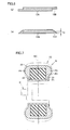
- the strip has a strip main body having a thickness T1 of 0.02 to 1.0 mm and ear portions formed on opposite sides of the strip main body.
- the ear portions have a thickness T2 smaller than thickness T1 and a width W2 of 0.5 mm to 5.0 mm.
- the strip is formed of a layer stack of the first layer and the second layer disposed adjacently to the carcass ply, wherein the second layer contains one of a styrene-isoprene-styrene block copolymer and a styrene-isobutylene block copolymer.
- the strip preferably has a width (W0) ranging from 5 mm to 60 mm.
- Another aspect of the present invention is a method for manufacturing the strip made of a thermoplastic elastomer, including the steps of (a) extruding a thermoplastic elastomer by an extruder having an extruder main body and an extrusion head to form a sheet having a horizontally-long rectangular cross section, (b) passing the sheet through a die roller and a nip roller to transfer a shape of the die roller on the sheet to form the strip having the ear portions on ends of the strip, and (c) detaching the strip from the die roller.
- a still another aspect of the present invention is a method for manufacturing a pneumatic tire, in which a strip is wound of an outer circumferential surface of the core body along a circumferential direction with its side edge offset to mold an inner liner having a shape close to a finished sectional shape or a tire, wherein (a) the strip is formed of one of a single layer including a first layer arranged in a tire innermost layer and made of a thermoplastic elastomer composition containing a styrene-isobutylene-styrene block copolymer and composite layers of the first layer and a second layer disposed adjacently to a carcass ply and made of a thermoplastic elastomer composition, and (b) the strip has a strip main body having a thickness T1 of 0.02 to 1.0 mm and ear portions formed on opposite sides of the strip main body, the ear portions having a thickness T2 smaller than thickness T1 and a width W2 of 0.5 mm to 5.0 mm.
- the core body preferably has an outer circumferential surface resembling a tire inner surface shape when 5% of internal pressure is applied to the tire.
- the core body preferably has an outer circumferential surface smaller than a tire inner surface shape when 5% of internal pressure is applied to the tire.
- An aspect of the present invention includes the step of molding the inner liner on the outer circumferential surface of the core body using the strip, and then assembling with another tire component to mold an unvulcanized tire, and the step of vulcanizing of removing the unvulcanized tire from the core body and inputting the unvulcanized tire into a vulcanization mold for vulcanization molding.
- the unvulcanized tire is preferably vulcanized with 0.1% to 2.0% of a radius stretch by expansion of a bladder disposed on an inner side of the unvulcanized tire.
- the unvulcanized tire is preferably vulcanized with 0.1% to 2.0% of a stretch in a radial direction by expansion of a bladder disposed on an inner side of the unvulcanized tire.
- Another aspect of the present invention is a method for manufacturing a pneumatic tire, including the steps of molding an unvulcanized tire molded using the strip on the outside of the core body, and inputting the unvulcanized tire and the core body together into a vulcanization mold and heating the vulcanization mold and the core body, thereby vulcanizing the tire.
- a ribbon-shaped strip of a thermoplastic elastomer composition having ear portions on the opposite ends thereof is wound on the outer circumferential surface of a core body of a tire to mold an inner liner, whereby uniformity of the tire and adhesive property with an adjacent carcass ply can be increased and flection crack growth can be reduced.
- An unvulcanized raw cover adjusted in thickness depending on the arrangement position of the inner liner can thus be designed.
- a buttress portion can be designed to be thick, which can improve gas barrier property and tire durability.
- the strip is of ribbon shape, it is applicable to tires of any tire size.
- the overall thickness can be made thin to achieve weight reduction while maintaining air shutoff property, so that rolling resistance can be reduced.
- the present invention relates to a method for manufacturing a pneumatic tire including an inner liner disposed inwardly in the tire.
- the inner liner is manufactured by spirally winding a ribbon-shaped strip on an outer circumferential surface of a core body of the tire.
- the ribbon-shaped strip has ear portions on the opposite ends thereof.
- the ribbon-shaped strip is manufactured by extrusion molding into a state close to a finished sectional shape.
- the strip is formed of a polymer layer stack of a single layer at least having a first layer or at least two layers.
- the first layer contains a styrene-isobutylene-styrene triblock copolymer (SIBS), and has a thickness ranging from 0.05 mm to 0.6 mm.
- SIBS styrene-isobutylene-styrene triblock copolymer
- SIB styrene-isobutylene diblock copolymer
- the second layer is arranged to be in contact with a rubber layer of a carcass ply.
- Fig. 1 is a schematic cross sectional view of the right half of the pneumatic tire.
- pneumatic tire 1 includes a tread portion 2, and a sidewall portion 3 and bead portions 4 so as to form a shape of toroid from the opposite ends of the tread portion.
- a bead core 5 is embedded in each of bead portions 4.
- a carcass ply 6 and a belt layer 7 are disposed.
- Carcass ply 6 is provided to extend from one bead portion 4 to the other bead portion, and has its ends anchored to bead cores 5.
- Belt layer 7, which is formed of at least two plies, is disposed outside a crown portion of carcass ply 6.
- Belt layer 7 is disposed such that two plies, which are formed of cords such as steel cords or aramid fibers, are arranged to allow the cords to cross each other between the plies normally at an angle of 5° to 30° relative to the tire circumferential direction.
- topping rubber layers can be provided on the outer sides of the ends of the belt layer to reduce detachment in the ends of the belt layer.
- organic fiber cords such as polyester, nylon, or aramid are arranged at substantially 90° relative to the tire circumferential direction.
- a bead apex 8 is disposed to extend in the sidewall direction.
- an inner liner 9 is disposed inwardly relative to carcass ply 6 in the direction of the tire radius, so as to extend from one bead portion 4 to the other bead portion 4.
- Strip 10 is configured such that a strip main body 10A has a thickness (T1) of 0.05 mm to 1.0 mm and ear portions 10B formed on the opposite sides of strip main body 10A have a thickness (T2) thinner than the thickness (T1) of the strip main body.
- Ear portions 10B preferably have a width (W2) of 0.5 mm to 5.0 mm so as to smooth out unevenness that would be formed on the surface wound on a drum.
- the strip has an overall width (W0) adjusted to range from 5 mm to 40 mm, and preferably ranges from 10 to 30 mm.
- the thickness (T1) of strip main body 10A needs to be in a range of 0.05 mm to 1.0 mm. If the thickness is less than 0.05 mm, extrusion molding will be difficult, and the number of times will be increased unnecessarily in order to form an inner liner of predetermined thickness. On the other hand, if the thickness exceeds 1.0 mm, a thick part will be formed at junctions on the opposite edges of the strip. Accuracy in contour shape will be deteriorated, flection durability of the inner liner will be decreased and weight reduction can no longer be expected.
- the thickness (T1) of the strip preferably ranges from 0.1 mm to 0.5 mm.
- the thickness (T2) of ear portions 10B ranges from 0.02 mm to 0.5 mm, and more preferably ranges from 0.05 mm to 0.2 mm. If the thickness (T2) of the ear portions is thinner than 0.02 mm, extrusion dimensional accuracy may be deteriorated. On the other hand, if the thickness (T2) of the ear portions is thicker than 0.5 mm, unevenness of the surface formed by adjacent portions of the strip may be increased.
- the thickness (T2) of the ear portions is defined as an average thickness in the widthwise direction when it is changed in thickness in the widthwise direction of the strip.
- the strip has a width (W0) ranging from 5 mm to 40 mm, preferably ranging from 10 to 30 mm.
- Ear portions 10B have a width (W2) adjusted to be in a range of 0.5 mm to 5.0 mm, preferably in a range of 0.8 mm to 3.0 mm so as to be wound on a drum and smooth out unevenness formed on the surface. If the width (W2) of the ear portions falls outside the range of 0.5 mm to 5.0 mm, the thickness dimension of the cross section of the inner liner formed by bonding the strip may become uneven. It should be noted that the value of (W2 ⁇ 2) is preferably not more than the value of (W0 ⁇ 0.5).
- ear portions 10B of the strip are preferably symmetric on the right and left ends of the strip main body, they can be asymmetric.
- the ear portion on the left end is formed with a constant thickness on the lower surface
- the ear portions on the opposite ends are formed with a constant thickness on the lower surface.
- strip main body 10A has its thickness (T1) forming a horizontally long, flat rectangular shape constant in the longitudinal direction.
- Fig. 5(a) shows a structure in which ear portions 10B of the strip partially have inclined sections.
- Fig. 5(b) shows an example in which ear portions 10B of the strip are formed only by inclined sections. It should be noted that, with the strip of the present invention, the ear portions of the strip adjacent to each other when winding the strip on the drum to form the inner liner can reduce a step difference at the strip ends. It should be noted that symmetrical or asymmetrical shape can be employed for the ear portions.
- Fig. 6(a) shows ear portions 10b formed by forming steps on the right and left ends of strip main body 10A, ear portions 10b being made thinner. Ear portions 10b are asymmetric on the opposite sides of the strip. Fig. 6(b) shows ear portions 10b gradually decreasing in thickness toward the lower surface of the strip at the right and left ends of strip main body 10A. In this case, when bonding the strip on the drum, a step difference will also be formed at ends of adjacent portions of the strip, but an inner liner sheet having a less uneven surface shape can be obtained.
- the strip of the present invention By forming the strip of the present invention into the above-described shape, adjacent ear portions of the strip fit together appropriately when winding the strip on the drum to form an inner liner, so that a junction of even thickness can be formed Not only these shapes but also various variations can be employed for the ear portions of the present invention. It should be noted that the thickness (T1) of strip main body 10A forms a horizontally long, flat rectangular shape substantially constant in the longitudinal direction.
- a method for manufacturing strip 10 will be described with reference to Fig. 2 .
- a strip manufacturing device 11 is composed of an extruder 13 for extrusion molding of a thermoplastic elastomer sheet 12 having a horizontally-long rectangular cross section and a nip roller 14A and a die roller 14B arranged in the vicinity of an extrusion port 16.
- Extruder 13 includes an extruder main body 13A having a screw shaft 15 and an extrusion head 13B forming a sheet of a thermoplastic elastomer discharged from this extruder main body 13A to extrude the sheet through extrusion port 16.
- Extruder main body 13A kneads and melts the input thermoplastic elastomer with screw shaft 15 driven by a motor having a slowdown function.
- Extrusion head 13B has a mouthpiece 17 for extrusion molding attached to the leading end of extruder main body 13A to constitute extrusion port 16.
- Nip roller 14A and die roller 14B constitute a pair of upper and lower rollers, and are held in the transverse direction orthogonal to the direction of extrusion through extrusion port 16. Nip roller 14A and die roller 14B are rotatably drive controlled at the same speed and in synchronization with each other.
- a gap between nip roller 14A and die roller 14B presents a shape resembling the sectional shape of strip 10 ( Fig. 4 ), as shown in Fig. 3 .
- "resembling" refers to being substantially similar to the sectional shape of strip 10. The similarity proportion is usually in a range of 0.50 to 0.90 in consideration of expansion, and a gap K2 is smaller.
- die roller 14B is provided with recessed sections 14a, 14b on the circumferential surface of a straight cylindrical roll body. Recessed sections 14a, 14b correspond to strip main body 10A ( Fig. 4 ). Therefore, ear portions 10B are molded by gaps K1 between nip roller 14A and die roller 14B, and strip main body 10A of Fig. 4 is molded by gap K2 formed by recessed sections 14a, 14b.
- Fig. 2 in manufacturing device 11, horizontally-long rectangular sheet 12 is formed first by extruder 13, and the shape of the die roller is transferred to the sheet on the condition that heat is not generated during die roll molding. Then, strip 12A with the ear portions is detached from die roller 14B by a free roller 18, and is processed into a final shape. Accordingly, dimensional accuracy and stability are increased, and manufacturing efficiency can be improved in that, for example, a knife cutting operation for width adjustment usually required in calender molding becomes unnecessary. Besides, variations in the thickness (T2) of ear portions 10B can be reduced, so that strip 10 of high quality can be manufactured.
- an opening height (HA1) of extrusion port 16 of extrusion head 13B at 2 to 7 times thickness T1 of the strip and to set an opening width (WA1) of extrusion port 16 at 0.7 to 1.0 times the width (W0) of the strip.
- the processing ratio in die roll molding will be excessively large, resulting in degraded quality and accuracy of strip 10. Particularly, accuracy in width will become unstable, which will require knife cutting to maintain width accuracy.
- the opening height (HA1) is less than twice T1
- the sheet thickness at the time of extrusion will be thin in order to obtain strip 12A of not more than 1.0 mm. Then, extrusion pressure will be higher, resulting in unstable dimensions.
- the opening width (WA1) exceeds W0, the processing ratio will become too small to the contrary to cause strip 12A to break, and dimensional stability will be deteriorated.
- mold release processing on the die roller, the nip roller and the free roller to be used in the molding step and the detaching step.
- examples of a conventional technique that can be adopted for the mold release processing include a method for subjecting the roller surface to nitriding (radical nitriding, Kanuc process) to obtain a Cr-N coating (hardness Hv: 200 to 800; thickness: 25 to 500 ⁇ m), plating obtained by impregnating hard chromium with Teflon® (hardness Hv: 800 to 1000; thickness: 25 to 1000 ⁇ m), a diamond-like carbon (DLC) coating (hardness Hv: 2000 to 7000; thickness: 0.2 to 3.0 ⁇ m), and a Teflon® coating (hardness Hv: 100 to 500; thickness: 0.1 to 0.5 ⁇ m).
- nitriding radical nitriding, Kanuc process
- a Cr-N coating hardness Hv: 200 to 800; thickness: 25 to 500 ⁇ m
- the strip of the present invention is implemented by a single layer of a thermoplastic elastomer composition or a polymer layer stack of a plurality of thermoplastic elastomers.
- the thermoplastic elastomer composition is a thermoplastic elastomer composition (hereinafter also referred to as a "first layer") containing a styrene-isobutylene-styrene block copolymer and at least one kind of a tackifier, a butyl-based rubber and a natural rubber.
- the strip of the present invention can be formed of a single layer of the first layer, but may be formed of a polymer layer stack of a plurality of layers including the first layer and a second layer of a thermoplastic elastomer composition disposed adjacently to the carcass ply.
- the compositions of the first layer and the second layer will be described below.
- the elastomer composition of the first layer contains a styrene-isobutylene-styrene triblock copolymer (SIBS) by 5 mass % to 100 mass % as a polymer component. If the SIBS is less than 5 mass %, air shutoff property may be deteriorated. From a viewpoint of ensuring air shutoff property, the blending quantity of the SIBS in the first layer is preferably in a range of 10 mass % to 80 mass %.
- SIBS styrene-isobutylene-styrene triblock copolymer
- An isobutylene block in the SIBS provides a polymer film made of the SIBS with excellent air permeability resistance. Therefore, when the polymer made of the SIBS is used for the inner liner, a pneumatic tire excellent in air permeability resistance can be obtained.
- the molecular structure of the SIBS is completely saturated except aromatic side chain, so that the SIBS is restrained from being deteriorated and hardened and therefore has excellent durability. Therefore, when a polymer film made of the SIBS is used for the inner liner, a pneumatic tire with excellent durability can be obtained.
- the molecular weight of the SIBS is not particularly limited, but the SIBS preferably has a weight average molecular weight of 50,000 to 400,000 measured through GPC measurement, in view of flowability, shaping step, rubber elasticity, and the like. When the weight average molecular weight thereof is less than 50,000, tensile strength and tensile elongation may be unfavorably decreased. On the other hand, when the weight average molecular weight thereof exceeds 400,000, extrusion workability unfavorably becomes bad.
- the SIBS preferably contains the styrene component at a content of 10 mass % to 30 mass %, preferably, 14 mass % to 23 mass %.
- the isobutylene block preferably has a degree of polymerization in a range of approximately 10,000 to 150,000, and the styrene block preferably has a degree of polymerization in a range of approximately 5,000 to 30,000, in view of rubber elasticity and handling (when the degree of polymerization is less than 10,000, each block will be in a liquid form).
- the SIBS can be obtained through a general living cationic polymerization method for a vinyl-based compound.
- each of Japanese Patent Laying-Open No. 62-48704 and Japanese Patent Laying-Open No. 64-62308 discloses that living cationic polymerization is possible between isobutylene and another vinyl compound and use of isobutylene and another compound for a vinyl compound allows for production of a polyisobutylene-based block copolymer.
- the first layer made of such an SIBS has a thickness t1 of 0.05 mm to 0.6 mm. If the thickness of the first layer is less than 0.05 mm, the first layer may be broken due to pressing pressure when vulcanizing the raw tire in which the polymer layer stack is applied to the inner liner, with the result that an air leakage phenomenon may take place in the resulting tire. On the other hand, if the thickness of the first layer exceeds 0.6 mm, the weight of the tire is increased to result in decreased performance in fuel efficiency. Further, the first layer preferably has a thickness of 0.05 mm to 0.4 mm.
- the first layer can be formed by forming the SIBS into the form of a film by means of a general method for forming thermoplastic resin or thermoplastic elastomer into a film, such as extrusion molding or calender molding.
- the elastomer composition of the first layer preferably contains a tackifier in a range of 0.1 part by mass to 100 parts by mass in the polymer component. If the tackifier is less than 0.1 part by mass, adhesion property with an adjacent tire component may be degraded. On the other hand, if the tackifier exceeds 100 parts by mass, tackiness will be too high, with the result that productivity is decreased and the gas barrier property is further decreased.
- the tackifier is preferably in a range of 1 part by mass to 50 parts by mass.
- the "tackifier” refers to a compounding agent for increasing tackiness of the elastomer composition. Examples of such a tackifier will be illustrated below.
- Typical tackifiers include a C9 petroleum resin and a C5 petroleum resin.
- a C9 petroleum resin is an aromatic petroleum resin obtained by polymerizing C5 to C9 fractions (mainly C9 fraction) in a mixed state.
- the C5 to C9 fractions are remnants when obtaining useful compounds, such as ethylene, propylene, and butadiene, by thermally decomposing naphtha.
- Examples thereof include products such as: ARKON P70, P90, P100, P125, P140, M90, M100, M115, and M135 (each provided by Arakawa Chemical Industries, Ltd, and having a softening point of 70°C to 145°C); I-MARV S100, S110, P100, P 125, and P140 (aromatic copolymer-based hydrogenated petroleum resins each provided by Idemitsu Petrochemical Ltd, having a softening point of 100°C to 140°C, having a weight average molecular weight of 700 to 900, and having a bromine number of 2.0g/100g to 6.0g/100g); and Petcoal XL (provided by TOSOH Corporation).
- ARKON P70, P90, P100, P125, P140, M90, M100, M115, and M135 each provided by Arakawa Chemical Industries, Ltd, and having a softening point of 70°C to 145°C
- a C5 petroleum resin is an aliphatic petroleum resin obtained by polymerizing C4 to C5 fractions (mainly C5 fraction) in a mixed state.
- the C4 to C5 fractions are remnants when obtaining useful compounds, such as ethylene, propylene, and butadiene, by thermally decomposing naphtha.
- useful compounds such as ethylene, propylene, and butadiene
- Examples thereof include products such as: Hilets G100 (provided by Mitsui Petrochemicals Industries, Ltd, and having a softening point of 100°C);
- Marcalets T100AS provided by Maruzen Petrochemical Co., Ltd, and having a softening point of 100°C); and Escorez 1102 (provided by Tonex Co., Ltd, and having a softening point of 110°C).
- terpene resin examples include products such as: YS resin PX800N, PX1000, PX1150, PX1250, and PXN1150N; and Clearon P85, P105, P115, P125, P135, P150, M105, M115, and K100 (each provided by Yasuhara Chemical Co., Ltd, and having a softening point of 75°C to 160°C).
- aromatic modified terpene resin examples include products such as: YS resin TO85, TO105, TO115, and TO125 (each provided by Yasuhara Chemical Co., Ltd, and having a softening point of 75°C to 165°C).
- terpene phenol resin examples include products such as: Tamanol 803L, and 901 (provided by Arakawa Chemical Industries Co., Ltd, and having a softening point of 120°C to 160°C); and YS Polyster U115, U130, T80, T100, T115, T145, and T160 (each provided by Yasuhara Chemical Co., Ltd, and having a softening point of 75°C to 165°C).
- Examples of the cumarone resin include a cumarone resin having a softening point of 90°C (provided by Kobe Oil Chemical Industrial Co., Ltd).
- Examples of the cumarone indene oil include products such as 15E (provided by Kobe Oil Chemical Industrial Co., Ltd, and having a fluidizing point of 15°C).
- rosin ester examples include products such as: ester gum AAL, A, AAV, 105, AT, H, HP, and HD (each provided by Arakawa Chemical Industries Co., Ltd, and having a softening point of 68°C to 110°C); and Hariester TF, S, C, DS70L, DS90, and DS130 (each provided by Harima Chemicals Inc., and having a softening point of 68°C to 138°C).
- ester gum AAL, A, AAV, 105, AT, H, HP, and HD each provided by Arakawa Chemical Industries Co., Ltd, and having a softening point of 68°C to 110°C
- Hariester TF, S, C, DS70L, DS90, and DS130 each provided by Harima Chemicals Inc., and having a softening point of 68°C to 138°C.
- hydrogenated rosin ester examples include products such as Superester A75, A100, A115, and A125 (each provided by Arakawa Chemical Industries Co., Ltd., and having a softening point of 70°C to 130°C).
- alkylphenol resin examples include products such as Tamanol 510 (provided by Arakawa Chemical Industries Co., Ltd, and having a softening point of 75°C to 95°C).
- DCPD examples include products such as Escorez 5300 (provided by Tonex Co., Ltd, and having a softening point of 105°C).
- a fully hydrogenated petroleum resin of the C9 petroleum resins is well compatible with the SIB, and can improve adhesive property without decreasing the gas barrier property. Further, it has an effect of decreasing a degree of viscosity, and therefore can be used advantageously for film extrusion molding.
- the elastomer composition of the first layer can contain a butyl rubber or a natural rubber (including an isoprene rubber) in a range of 60 mass % to 95 mass % as a polymer component. If the butyl rubber or the natural rubber (including an isoprene rubber) is less than the 60 mass %, viscosity will be high and extrusion workability will be deteriorated. Weight reduction by thickness reduction may not be achieved. If the butyl rubber or the natural rubber exceeds 95 mass %, air shutoff property may be deteriorated. In order to increase unvulcanization adhesive property and vulcanization adhesive property of the elastomer composition, the butyl rubber or the natural rubber is preferably in a range of 70 mass % to 90 mass %.
- the second layer used for the strip of the present invention preferably contains at least one of the SIS layer made of a styrene-isoprene-styrene triblock copolymer (hereinafter, also referred to as "SIS”) and the SIB layer made of a styrene-isobutylene diblock copolymer (hereinafter, also referred to as "SIB").
- SIS styrene-isoprene-styrene triblock copolymer
- SIB styrene-isobutylene diblock copolymer
- the isoprene block of the styrene-isoprene-styrene triblock copolymer (SIS) is a soft segment. Hence, a polymer film made of the SIS is likely to adhere to a rubber component through vulcanization. Therefore, when a polymer film made of the SIS is used for the inner liner, a pneumatic tire excellent in durability can be obtained because the inner liner is excellent in adhesive property with the rubber layer of the carcass ply, for example.
- the molecular weight of the SIS is not particularly limited, but the SIS preferably has a weight average molecular weight of 100,000 to 290,000 measured through GPC measurement, in view of rubber elasticity and moldability. When the weight average molecular weight thereof is less than 100,000, tensile strength may be unfavorably decreased. On the other hand, when the weight average molecular weight thereof exceeds 290,000, extrusion workability unfavorably becomes bad.
- the SIS preferably contains the styrene component at a content of 10 mass % to 30 mass % in view of tackiness, adhesive property, and rubber elasticity.
- the isoprene block has a degree of polymerization in a range of approximately 500 to 5,000 and the styrene block has a degree of polymerization in a range of approximately 50 to 1,500 in view of rubber elasticity and handling.
- the SIS can be obtained through a general polymerization method for a vinyl-based compound, such as the living cationic polymerization method.
- the SIS layer can be obtained by forming the SIS into the form of a film by means of a general method for forming thermoplastic resin or thermoplastic elastomer into a film, such as extrusion molding or calender molding.
- the isobutylene block of the styrene-isobutylene diblock copolymer (SIB) is a soft segment.
- SIB styrene-isobutylene diblock copolymer
- a polymer film made of the SIB is likely to adhere to a rubber component through vulcanization. Therefore, when a polymer film made of the SIB is used for the inner liner, a pneumatic tire excellent in durability can be obtained because the inner liner is excellent in adhesive property with an adjacent rubber forming the carcass or an insulation, for example.
- a linear SIB is preferably used in view of rubber elasticity and adhesive property.
- the molecular weight of the SIB is not particularly limited, but the SIB preferably has a weight average molecular weight of 40,000 to 120,000 measured through GPC measurement, in view of rubber elasticity and moldability. When the weight average molecular weight thereof is less than 40,000, tensile strength may be unfavorably decreased. On the other hand, when the weight average molecular weight thereof exceeds 120,000, extrusion workability unfavorably becomes bad.
- the SIB preferably contains the styrene component at a content of 10 mass % to 35 mass %, in view of tackiness, adhesive property, and rubber elasticity.
- the isobutylene block has a degree of polymerization in a range of approximately 300 to 3,000 and the styrene block has a degree of polymerization in a range of approximately 10 to 1,500 in view of rubber elasticity and handling.
- the SIB can be obtained through a general polymerization method for a vinyl-based compound, such as the living cationic polymerization method.
- WO2005/033035 discloses a manufacturing method wherein the SIB is obtained by adding methylcyclohexane, n-butyl chloride, and cumyl chloride into an agitator, cooling them to -70°C, reacting them for 2 hours, then adding a large amount of methanol to stop the reaction, and performing vacuum-drying at 60°C.
- the SIB layer can be obtained by forming the SIB into the form of a film through a general method for forming thermoplastic resin or thermoplastic elastomer into a film, such as extrusion molding or calender molding.
- the thickness of the second layer ranges from 0.01 mm to 0.3 mm.
- the thickness of the second layer refers to the thickness of the SIS layer if the second layer is composed only of the SIS layer, refers to the thickness of the SIB layer if the second layer is composed only of the SIB layer, and refers to the total thickness of the SIS layer and the SIB layer if the second layer is composed of two layers of the SIS layer and the SIB layer.
- the thickness of the second layer is less than 0.01 mm, the second layer may be broken due to pressing pressure when vulcanizing the raw tire in which the polymer layer stack is applied to the inner liner, with the result that vulcanization adhesion strength may be decreased.
- the thickness of the second layer exceeds 0.3 mm, the weight of the tire is increased to result in decreased performance in fuel efficiency.
- the second layer preferably has a thickness of 0.05 mm to 0.2 mm.
- the method for manufacturing the pneumatic tire of the present invention includes a method for molding an inner liner, a step of molding a raw cover and a step of vulcanizing the raw cover. These steps will now be described.
- the inner liner is formed by winding strip 10 on an outer circumferential surface 22 of core body N with its side edge offset in the circumferential direction.
- strip 10 is of a ribbon shape having width W0 of about 5 mm to 60 mm and thickness T1 of about 0.5 mm to 1.0 mm, for example.
- an inner liner 9G formed of strip 10 can be disposed in a partial or an entire area of outer circumferential surface 22 of core body N, as shown in Fig. 8 .
- This method for molding a strip is called a strip winding method, which can be employed for forming a complicated three-dimensional shape. It should be noted that, for molding of the inner liner, a wide strip may be wound in a tread region, and the strip winding method may be adopted for the side portions on the opposite sides thereof.
- an uneven step difference (d0) formed in the case of using a conventional strip of rectangular cross section having no ear portions is about twice the unevenness in the case of the strip having the ear portions.
- the use of the strip having the ear portions facilitates making the inner liner resemble a finished sectional shape required of the inner liner.
- a smooth contour can be obtained, and surface cracks can be prevented from occurring after vulcanization.
- the inner liner can be formed by approximately the same number of times of winding as in the case of a conventional strip of the same thickness, which can restrain production efficiency from being deteriorated and air from remaining.
- the width of overlapping portions at the time of winding the strip is adjusted depending on the finish thickness of a tire component to be formed, inner surface smoothness and sectional shape, it is typically adjusted to be in a range of 1 mm to 40 mm. If the width of the overlapping portions deviates from the range of 1 mm to 40 mm, accuracy in contour shape of the inner liner may be deteriorated.
- inner liner 9 is affixed to the outside of core body N, and the base of a clinch rubber 4G represents a rectangular cross sectional shape, for example, and is wound on a flange surface 23 into a ring shape, as shown in Fig. 10 .
- Core body N has three-dimensional outer circumferential surface 22 resembling the tire inner surface shape when 5% of internal pressure is applied to a product tire, and pair of flange surfaces 23 connected to the bead-side ends of this outer circumferential surface and extending outwardly in the axial direction.
- the tire inner surface shape refers to the inner surface shape of a product tire.
- "when 5% of internal pressure is applied to a product tire” shall refer to a state where pressure has been reduced from the normal internal pressure of the tire to 5% of the normal internal pressure.
- the sectional shape of a tire in this 5% internal pressure applied state is similar to the sectional shape of the tire in a vulcanization mold. Therefore, by making outer circumferential surface 22 of core body N resemble the inner surface shape of the tire when 5% of internal pressure is applied, strain which is elongation of a raw cover during vulcanization molding can be reduced, and tire uniformity can be improved.
- Fig. 7 illustrates an assembly type core body N formed of a plurality of split pieces P1 to P4 that can be divided in the tire circumferential direction. Therefore, after forming raw cover 1G on the outside of core body N, respective split pieces P1 to P4 can be decomposed and taken out from raw cover 1G in a predetermined order.
- Core body N is not limited to the assembly type as in the present embodiment, but various types having rigidity such that its outer circumferential surface 22 is not substantially deformed during raw cover molding, such as an expansion type through the use of hydrostatic pressure, a contraction type, a drum type that can increase and decrease in diameter in the direction of the tire radius, can be adopted.
- Core body N of the present embodiment is supported by support shaft D in a cantilever and rotatable manner.
- a metallic material such as duralumin, for example, that can resist heat and pressure during the vulcanization is suitable.
- a resin material excellent in handling or the like is suitable for core body N.
- the bead core is formed by spirally winding a bead wire supplied continuously, for example, by several turns so as to be stacked from the base of the clinch rubber in the direction of the tire radius.
- Spiral winding of the bead wire is desirably carried out with, for example, a ring-shaped patch that can create a small clearance with the outer surface of inner liner 9G being mounted on flange surface 23.
- a toroidal carcass is molded on the outside of the inner liner molded on the core body, and then, as shown in Fig. 12 , the step of arranging a bead core 5G and an apex 8G on the outside is performed. Moreover, clinch rubber 4G is arranged on the outside thereof in the tire axial direction. Furthermore, a belt layer 7G, a sidewall rubber 3G and a tread rubber 2G are arranged, respectively.
- each tire component may be implemented by winding an integral extrusion type component, one having a complicated cubic shape, such as sidewall rubber 3G, for example, can be formed by the above-described strip winding method as appropriate. In this way, raw cover 1G is formed on the outside of core body N.
- core body N is removed from the inside of raw cover 1G, and then, as shown in Fig. 13 , the vulcanization molding step of vulcanization molding raw cover 1G from which the core body has been removed with a vulcanization mold M is performed.
- vulcanization mold M has a molding surface Ma to come into contact with the outer surface of raw cover 1G to give it a predetermined shape.
- Vulcanization mold M is implemented by a widely known divided-type mold or the like.
- a bladder B that can expand and contract is disposed in the inside of raw cover 1G arranged in vulcanization mold M. Expanded bladder B comes into contact with the inside of raw cover 1G and strongly presses raw cover 1G against above-mentioned molding surface Ma, thereby ensuring vulcanization molding of a tire. By this action, a stretch in the radial direction and a radius stretch may occur in raw cover 1G.
- the vulcanization molding step is carried out such that the stretch in the radial direction and/or the radius stretch of raw cover 1G present/presents a small value. This prevents the ends of the carcass cord from varying in the vulcanization molding step, so that a pneumatic tire uniformized with high accuracy in the tire circumferential direction is reliably manufactured. Moreover, the tension which acts upon the cord of belt layer 7 is controlled to be very small, which can reduce angle variations in the belt cord during vulcanization. Thus, the cord angle can be controlled with very high accuracy. Therefore, according to the manufacturing method of the present embodiment, a pneumatic tire further having excellent uniformity can be manufactured.
- the stretch in the radial direction and/or the radius stretch of raw cover 1 G at the time of vulcanization molding are/is preferably not more than 2.0%, more preferably not more than 1.5%, and particularly preferably not more than 1.0%.
- This stretch adjustment can be performed as appropriate by, for example, changing the relative relation between the shape of outer circumferential surface 22 of core body N and the shape of molding surface Ma of vulcanization mold M. That is, the stretch is elongated by making outer circumferential surface 22 of core body N relatively smaller than molding surface Ma of vulcanization mold M. On the other hand, the stretch can be made smaller by making outer circumferential surface 22 of core body N relatively larger.
- the above-mentioned "radius stretch” can be calculated by the following formula from an inner diameter Ri at the position of a tire equator C of a resulting tire in the above-mentioned 5% internal pressure applied state and an outer diameter Ro at the position of an equator Nc of core body N.
- Radius Stretch % Ri - Ro ⁇ 100 / Ro
- above-mentioned inner diameter Ri can be approximately obtained by approximately reducing the distance twice the tread thickness in tire design dimensions from an inner diameter Mr of a section of mold surface Ma of vulcanization mold M where the tire equator is vulcanized (not including a projection Mp for tread groove molding).
- the stretch in the radial direction can be calculated by the following formula from a path length (which is a so-called peripheral length measured along the contour; the same also applies below) Li in the radial direction from one bead toe to the other bead toe on the tire inside in the 5% internal pressure applied state of a resulting tire and a path length Lo (shown in Fig. 12 ) of the outer circumferential surface of core body N.
- Radius in the Direction % Li - Lo ⁇ 100 / Lo
- the lower limit of stretch is 0%. That is, the tire sectional shape in the 5% internal pressure applied state of a resulting tire and raw cover 1G may have substantially the same shape, for example. This is because, in raw cover 1G molded according to the present invention, the tension of the carcass cord is uniformized on the tire circumference as compared with the case of experiencing the conventional expanding and deforming step.
- the tension of the carcass cord in raw cover 1G is not completely uniformized on the tire circumference since manufacturing errors of the carcass ply, errors at the time of affixing the carcass ply to core body N, and the like exist.
- vulcanization is desirably performed while giving a much smaller stretch to raw cover 1G than in the conventional case to equalize nonuniform tension. Accordingly, when there is a loosened carcass cord on the tire circumference in raw cover 1G, for example, the loosening can be removed at the time of vulcanization.
- outer circumferential surface 22 of core body N such that the radius stretch and/or the stretch in the radial direction of the raw cover during vulcanization are/is more preferably not less than 0.1%, still more preferably not less than 0.2%, and particularly preferably not less than 0.3%.
- raw cover 1G can be vulcanized together with core body N.
- the steps of removing and transferring raw cover 1G and the like will become unnecessary, which can prevent deformation of raw cover 1G that would occur in such steps. It is helpful to manufacture a pneumatic tire further having excellent uniformity.
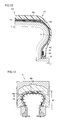
- the inner liner in the pneumatic tire of the present invention is preferably manufactured using a polymer layer stack PL formed of a plurality of layers of a first layer and a second layer.
- the second layer of polymer layer stack PL i.e., an SIS layer PL2 or an SIB layer PL3 is disposed outwardly in the direction of the tire radius in contact with carcass ply 61.
- adhesive strength can be increased between carcass 6 and SIS layer PL2 or SIB layer PL3.
- the inner liner and the rubber layer of carcass ply 61 are adhered to each other in an excellent manner.
- the pneumatic tire can have excellent air permeability resistance and durability.
- Fig. 14 shows an arrangement of the inner liner formed of the polymer layer stack in the vulcanized tire of the present invention.
- a polymer layer stack PL is formed of a layer PL1 containing the SIB S serving as the first layer, and SIS layer PL2 serving as the second layer.
- adhesive strength between SIS layer PL2 and carcass 61 can be increased in the step of vulcanizing the tire. Accordingly, in the resulting pneumatic tire, the inner liner and the rubber layer of carcass ply 61 are adhered to each other in an excellent manner.
- the pneumatic tire can have excellent air permeability resistance and durability.
- polymer layer stack PL is formed of layer PL1 containing the SIBS serving as the first layer, and SIB layer PL3 serving as the second layer.
- adhesive strength between SIB layer PL3 and carcass 61 can be increased in the step of vulcanizing the tire. Accordingly, in the resulting pneumatic tire, the inner liner and the rubber layer of carcass ply 61 are adhered to each other in an excellent manner.
- the pneumatic tire can have excellent air permeability resistance and durability.
- polymer layer stack PL is formed of layer PL1 containing the SIBS serving as the first layer, SIS layer PL2 and SIB layer PL3 both serving as the second layer.
- SIBS layer PL1, SIS layer PL2, and SIB layer PL3 are stacked on one another in this order.
- polymer layer stack PL is formed of layer PL1 containing the SIBS serving as the first layer, and SIB layer PL3 and SIS layer PL2 both serving as the second layer.
- SIBS layer PL1, SIB layer PL3, and SIS layer PL2 are stacked on one another in this order.
- thermoplastic elastomers (SIB, SIBS, and SIS) were used for manufacturing of the strip of the present invention.
- SIBSTAR 102T (Shore A hardness: 25; the content of the styrene component: 25 mass %; weight average molecular weight: 100,000)" provided by Kaneka Corporation was used.
- D1161JP (the content of the styrene component: 15 mass %; weight average molecular weight: 150,000) provided by Kraton Polymers was used.
- the SIBS and the SIS were implemented by commercially available pellets and the SIB obtained by the above-described manufacturing method was used. They were blended by the following formulation with a Banbury mixer and a twin-screw extruder.
- thermoplastic elastomer strip the first layer and the second layer were used to produce a ribbon-shaped sheet (thickness: 0.3 mm) of two-layer structure by coextrusion with a die extruder shown in Figs. 2 and 3 .
- the extrusion conditions are as follows:
- strip 12A was passed through nip roller 14A and die roller 14B to manufacture strip 12A with the ear portions of predetermined shape formed on the opposite ends.
- ribbon-shaped sheet 12 has a multilayer structure obtained by coextruding thermoplastic elastomers of the first layer and the second layer using the above-mentioned extruder. Then, the strip was passed by a free roller 18 and detached from the die roller to obtain strip 12A having a sectional structure shown in Fig. 4 .
- strip 10 has widths (W0, WA) and thickness (T1) and ear portions 10B have width (W2) and thickness (T2) as shown in Table 3.
- the above-described strip was wound on the outer circumferential surface of the core body as shown in Fig. 8 such that overlapping portions have a width of 18 mm, thereby forming a 0.3-mm-thick inner liner with adjacent ear portions of the strip forming junctions together.
- Carbon Black (CB) “SEAST V (N660, N2SA: 27m2/g)” provided by Tokai Carbon Co., Ltd.
- Zinc oxide “Zinc White No. 1” provided by Mitsui Mining and Smelting Co., Ltd.
- Stearic Acid “Stearic Acid LUNAC S30" provided by Kao Corp.
- a pneumatic tire of tire size of 195/65R15 was prototyped using an inner liner obtained by molding a strip based on the specifications shown in Table 1 on a drum. It should be noted that press vulcanization was performed for 20 minutes at 170°C. Then, the tire was cooled for 3 minutes at 100°C without removing the tire from the vulcanization mold, and then was removed from the vulcanization mold. It should be noted that each Example is a strip provided with ear portions.
- the core body has an outer circumferential surface resembling the tire inner surface shape when 5% of internal pressure is applied to the tire. Furthermore, the radius stretch of each Comparative Example and Example is 1.0%, and the stretch in the radial direction is 1.0%.
- vulcanization tackiness in each Example was expressed in an index with Comparative Example 1 being regarded as a reference. It should be noted that as the index of the unvulcanization tackiness is larger, the unvulcanization tackiness is higher.
- Unvulcanized rubbers of the first layer and the carcass ply layer as well as the second layer and the carcass ply were bonded together. Then, they were vulcanized at 170°C for 20 minutes. In this way, samples for measurement of vulcanization adhesion strength were fabricated. Vulcanization adhesion strength was measured by measuring detachment force using a tension tester. According to the below-described formula, vulcanization adhesion strength for each blend was expressed in an index with Comparative Example 1 being regarded as a reference. It should be noted that as the index of the vulcanization adhesion strength is larger, the vulcanization adhesion strength is higher.
- a tire that satisfied the following conditions in any one of (a) to (e) below was rated B or C as a total judgment. When a plurality of judgments applied, one of lower evaluation was adopted.
- Examples 1, 2 and 5 are examples where the strip is only formed of the first layer.
- Examples 1 to 4 and Examples 8 to 11 are examples where the first layer contains a tackifier.
- Examples 5 to 7 are examples where the first layer contains IIR. It is recognized that Examples of the present invention excels Comparative Example 1 in all of unvulcanization tackiness, vulcanization adhesion strength, uniformity, and flection crack growth test.
- the strip and the method for manufacturing the same of the present invention can be applied to a pneumatic tire for track/bus, a pneumatic tire for heavy vehicle, or the like, besides a pneumatic tire for passenger car.
- 1 pneumatic tire
- 2 tread portion
- 3 sidewall portion
- 4 bead portion
- 5 bead core
- 6 carcass ply
- 7 belt layer
- 8 bead apex
- 9 inner liner
- 10 strip
- 11 strip manufacturing device
- 12 sheet
- 13 extruder
- 14A, 14B die roller
- 15 screw shaft
- 16 extrusion port
- 17 mouthpiece
- 18 free roller
- PL polymer layer stack.
Abstract
Description
- The present invention relates to a strip for an inner liner used for a pneumatic tire, a method for manufacturing the strip, and a method for manufacturing a pneumatic tire including the strip.
- In recent years, in response to strong social demands for low fuel consumption of vehicles, weight reduction of tires has been sought. Among tire members, weight reduction and the like of an inner liner also have begun. The inner liner is disposed inwardly in a tire, and has a function of reducing an amount of leakage of air from inside to outside of the pneumatic tire.
- Currently, a rubber composition for such an inner liner employs, for example, a rubber blend mainly containing a butyl rubber. The rubber blend contains the butyl rubber by 70 mass % to 100 mass %, and a natural rubber by 30 mass % to 0 mass %. In this way, the tire is provided with improved air permeability resistance. In addition to butylene, the rubber blend mainly containing the butyl rubber contains isoprene by approximately 1 mass %, which acts with sulfur, vulcanization accelerator, and zinc white to achieve cross-linking between rubber molecules. In the case of normal blend, the above-described butyl-based rubber needs to have a thickness of 0.6 mm to 1.0 mm for a tire of a passenger car, and needs to have a thickness of approximately 1.0 mm to 2.0 mm for a tire of a truck/bus. In order to achieve weight reduction of such tires, use of polymer, which is more excellent in air permeability resistance than the butyl-based rubber and can provide an inner liner layer with a thinner thickness, has been requested.
- Patent Literature 1 (Japanese Patent Laying-Open No.
7-215007 11-254906 - Conventionally, in order to achieve weight reduction of a tire, it has been proposed to use a film made of a material including thermoplastic resin, instead of the above-described rubber composition. However, when a tire is manufactured using an inner liner of thin thermoplastic resin, the inner liner partially becomes too thin due to pressure in a vulcanization step, with the result that the finishing gauge of the inner liner in the resulting tire product becomes thinner than the designed gauge. In the thin portion of the inner liner thus finished, a phenomenon (open thread) in which a carcass cord looks to stand out takes place, thus giving a user an impression of bad inner appearance. In addition, when the inner liner is thin, gas barrier property becomes partially bad to decrease tire internal pressure, with the result that the tire may burst in the worst case.
- A thermoplastic resin composition having excellent gas barrier property has low tackiness to the core body, and particularly, has a small curvature R from a position in the vicinity of the bead portion to a position in the vicinity of a buttress portion on the outer circumferential surface of the core body. Thus, it cannot be adhered to such a structure that is to be stuck on a side surface to maintain tackiness. Furthermore, tackiness is low at places where portions of the thermoplastic resin composition having excellent gas barrier property overlap one another to form a strip structure, and the composition is loosened when it is wound around the core body.
- Meanwhile, during traveling with the tire, large shear strain acts on a vicinity of a shoulder portion in the inner liner. When the material including the thermoplastic resin is used as the inner liner, this shear strain is likely to cause detachment at an adhesion interface between the inner liner and the carcass ply, with the result that air leakage takes place from the tire, disadvantageously.
- Patent Literature 3 (International Publication
WO2008/029781 ) discloses a technique for manufacturing a tire using a strip of film layer stack in which a thermoplastic resin and a thermoplastic elastomer are blended. Here, with the film layer stack, gas barrier property and adhesive property can be improved, whereby bonding can be achieved between the ribbon-shaped strips. However, with this technique, the strip may be unlikely to be adhered to the outer circumferential surface of the core body, particularly, the side surface from the bead portion to the buttress portion, and may peel off the core body, so that molding would not be performed. - Patent Literature 4 (Japanese Patent Laying-Open No.
2000-254980 - Conventionally, an inner liner used for a pneumatic tire is obtained in general by continuously extrusion molding into a predetermined finished sectional shape from a rubber extruder or the like. The finished sectional shape is determined by a mouthpiece provided at a head part of the rubber extruder. In the conventional method for extrusion molding into a finished sectional shape, the sectional size of a rubber component is large, so that a large size rubber extruder needs to be used. As a result, a production line cannot be reduced in size. Moreover, to solve problems of deteriorated productivity in small quantity, large variety production and the like, various types of mouthpieces should be prepared depending on the types of tire and the like, and besides, exchanging and adjusting operations of the mouthpiece and the like are required every time the type of tire to be manufactured is changed.
- However, when forming a tire component by a ribbon-shaped rubber strip, workability is disadvantageous due to tackiness between rubber compositions and the rubber component formed of the rubber strip deforms disadvantageously during storage.
- Patent Literature 5 (Japanese Patent Laying-Open No.
9-19987 -
- PTL 1: Japanese Patent Laying-Open No.
7-215007 - PTL 2: Japanese Patent Laying-Open No.
11-254906 - PTL 3: International Publication
WO2008/029781 - PTL 4: Japanese Patent Laying-Open No.
2000-254980 - PTL 5: Japanese Patent Laying-Open No.
9-19987 - The present invention provides a ribbon-shaped strip used for an inner liner and a method for manufacturing the strip. A conventional strip has a flat rectangular cross sectional shape. Therefore, when winding the ribbon-shaped strip of predetermined width to produce a wider sheet, overlapping portions on the opposite ends of the strip are made thicker. A first purpose of the present invention is to reduce unevenness of the thickness of an inner liner by providing ear portions for a ribbon-shaped strip.
- Moreover, the present invention reduces rolling resistance of a tire by achieving weight reduction through the use of a strip of one or more layers of a thermoplastic elastomer. In addition, since a tackifier is blended, the inner liner can be molded while holding the strip in a region where a curve is tight on a side surface of the core body. As a result, the inner liner can be prevented from breaking and deforming by heat and pressure of a bladder in a vulcanization step, thereby avoiding cracks in the surface and/or air remaining inside.
- Furthermore, the present invention improves uniformity of the tire by molding the inner liner with the strip of a thermoplastic elastomer wound on the outer circumferential surface of the core body, the inner liner thus resembling the inner surface shape of a vulcanized tire. The present invention also has an object to improve adhesive property between the inner liner and the carcass ply, thereby reducing crack growth following repeated flection deformation during traveling with the tire.
- The present invention is a strip to be wound on an outer circumferential surface of a core body in a circumferential direction to form an inner liner having a shape close to a finished sectional shape of a tire. The strip is formed of one of a single layer including a first layer arranged in a tire innermost layer and composite layers of the first layer and a second layer disposed adjacently to a carcass ply and made of a thermoplastic elastomer composition. The first layer is a thermoplastic elastomer composition containing a styrene-isobutylene-styrene block copolymer and at least one kind of a tackifier, a butyl-based rubber and a natural rubber. The strip has a strip main body having a thickness T1 of 0.02 to 1.0 mm and ear portions formed on opposite sides of the strip main body. The ear portions have a thickness T2 smaller than thickness T1 and a width W2 of 0.5 mm to 5.0 mm.
- Preferably, the strip is formed of a layer stack of the first layer and the second layer disposed adjacently to the carcass ply, wherein the second layer contains one of a styrene-isoprene-styrene block copolymer and a styrene-isobutylene block copolymer. The strip preferably has a width (W0) ranging from 5 mm to 60 mm.
- Another aspect of the present invention is a method for manufacturing the strip made of a thermoplastic elastomer, including the steps of (a) extruding a thermoplastic elastomer by an extruder having an extruder main body and an extrusion head to form a sheet having a horizontally-long rectangular cross section, (b) passing the sheet through a die roller and a nip roller to transfer a shape of the die roller on the sheet to form the strip having the ear portions on ends of the strip, and (c) detaching the strip from the die roller.
- A still another aspect of the present invention is a method for manufacturing a pneumatic tire, in which a strip is wound of an outer circumferential surface of the core body along a circumferential direction with its side edge offset to mold an inner liner having a shape close to a finished sectional shape or a tire, wherein (a) the strip is formed of one of a single layer including a first layer arranged in a tire innermost layer and made of a thermoplastic elastomer composition containing a styrene-isobutylene-styrene block copolymer and composite layers of the first layer and a second layer disposed adjacently to a carcass ply and made of a thermoplastic elastomer composition, and (b) the strip has a strip main body having a thickness T1 of 0.02 to 1.0 mm and ear portions formed on opposite sides of the strip main body, the ear portions having a thickness T2 smaller than thickness T1 and a width W2 of 0.5 mm to 5.0 mm.
- The core body preferably has an outer circumferential surface resembling a tire inner surface shape when 5% of internal pressure is applied to the tire. The core body preferably has an outer circumferential surface smaller than a tire inner surface shape when 5% of internal pressure is applied to the tire.
- An aspect of the present invention includes the step of molding the inner liner on the outer circumferential surface of the core body using the strip, and then assembling with another tire component to mold an unvulcanized tire, and the step of vulcanizing of removing the unvulcanized tire from the core body and inputting the unvulcanized tire into a vulcanization mold for vulcanization molding.
- In the step of vulcanizing, the unvulcanized tire is preferably vulcanized with 0.1% to 2.0% of a radius stretch by expansion of a bladder disposed on an inner side of the unvulcanized tire. In the step of vulcanizing, the unvulcanized tire is preferably vulcanized with 0.1% to 2.0% of a stretch in a radial direction by expansion of a bladder disposed on an inner side of the unvulcanized tire.
- Another aspect of the present invention is a method for manufacturing a pneumatic tire, including the steps of molding an unvulcanized tire molded using the strip on the outside of the core body, and inputting the unvulcanized tire and the core body together into a vulcanization mold and heating the vulcanization mold and the core body, thereby vulcanizing the tire.
- According to the present invention, a ribbon-shaped strip of a thermoplastic elastomer composition having ear portions on the opposite ends thereof is wound on the outer circumferential surface of a core body of a tire to mold an inner liner, whereby uniformity of the tire and adhesive property with an adjacent carcass ply can be increased and flection crack growth can be reduced.
- An unvulcanized raw cover adjusted in thickness depending on the arrangement position of the inner liner can thus be designed. For example, merely a buttress portion can be designed to be thick, which can improve gas barrier property and tire durability. Moreover, because the strip is of ribbon shape, it is applicable to tires of any tire size. Particularly because of the use of a plurality of layers of thermoplastic elastomers, the overall thickness can be made thin to achieve weight reduction while maintaining air shutoff property, so that rolling resistance can be reduced.
-
-
Fig. 1 is a schematic cross sectional view of the right half of a pneumatic tire of the present invention. -
Fig. 2 is a schematic view of a device manufacturing a strip of the present invention. -
Fig. 3 is a cross sectional view showing the distance between a nip roller and a die roller in the manufacturing device shown inFig. 2 . -
Fig. 4 is a schematic cross sectional view of a strip of the present invention. -
Fig. 5 is a schematic cross sectional view of strips of the present invention. -
Fig. 6 is a schematic cross sectional view of strips of the present invention. -
Fig. 7 is a cross sectional view of a core body used for molding of the tire of the present invention. -
Fig. 8 is a schematic view showing a method of molding an inner liner using a strip on the outer circumferential surface of the core body. -
Fig. 9 is an enlarged cross sectional view showing an arrangement of the strip ofFig. 8 . -
Fig. 10 is a schematic view of the inner liner molded on the outer circumferential surface of the core body. -
Fig. 11 is a schematic view showing a method for manufacturing an inner liner using a conventional strip. -
Fig. 12 is a cross sectional view of a molded unvulcanized tire. -
Fig. 13 is a cross sectional view of the unvulcanized tire placed in a vulcanization mold. -
Fig. 14 is a schematic cross sectional view showing an arrangement of an inner liner and a carcass ply. - The present invention relates to a method for manufacturing a pneumatic tire including an inner liner disposed inwardly in the tire. The inner liner is manufactured by spirally winding a ribbon-shaped strip on an outer circumferential surface of a core body of the tire. The ribbon-shaped strip has ear portions on the opposite ends thereof. Here, the ribbon-shaped strip is manufactured by extrusion molding into a state close to a finished sectional shape.
- The strip is formed of a polymer layer stack of a single layer at least having a first layer or at least two layers. The first layer contains a styrene-isobutylene-styrene triblock copolymer (SIBS), and has a thickness ranging from 0.05 mm to 0.6 mm. The second layer contains at least one of a styrene-isoprene-styrene triblock copolymer (SIS) and a styrene-isobutylene diblock copolymer (SIB), and has a thickness of 0.01 mm to 0.3 mm. The second layer is arranged to be in contact with a rubber layer of a carcass ply.
- A pneumatic tire manufactured by the present invention will be described based on the drawings.
Fig. 1 is a schematic cross sectional view of the right half of the pneumatic tire. In the figure, pneumatic tire 1 includes atread portion 2, and asidewall portion 3 andbead portions 4 so as to form a shape of toroid from the opposite ends of the tread portion. In each ofbead portions 4, abead core 5 is embedded. Further, acarcass ply 6 and abelt layer 7 are disposed.Carcass ply 6 is provided to extend from onebead portion 4 to the other bead portion, and has its ends anchored to beadcores 5.Belt layer 7, which is formed of at least two plies, is disposed outside a crown portion ofcarcass ply 6. -
Belt layer 7 is disposed such that two plies, which are formed of cords such as steel cords or aramid fibers, are arranged to allow the cords to cross each other between the plies normally at an angle of 5° to 30° relative to the tire circumferential direction. It should be noted that topping rubber layers can be provided on the outer sides of the ends of the belt layer to reduce detachment in the ends of the belt layer. Further, in the carcass ply, organic fiber cords such as polyester, nylon, or aramid are arranged at substantially 90° relative to the tire circumferential direction. On each of the opposite ends of the carcass ply and in the vicinity ofbead core 5, abead apex 8 is disposed to extend in the sidewall direction. Further, aninner liner 9 is disposed inwardly relative to carcass ply 6 in the direction of the tire radius, so as to extend from onebead portion 4 to theother bead portion 4. <Shape of Strip> - Each of
Figs. 4 to 6 shows a cross sectional view of an embodiment of astrip 10.Strip 10 is configured such that a stripmain body 10A has a thickness (T1) of 0.05 mm to 1.0 mm andear portions 10B formed on the opposite sides of stripmain body 10A have a thickness (T2) thinner than the thickness (T1) of the strip main body.Ear portions 10B preferably have a width (W2) of 0.5 mm to 5.0 mm so as to smooth out unevenness that would be formed on the surface wound on a drum. The strip has an overall width (W0) adjusted to range from 5 mm to 40 mm, and preferably ranges from 10 to 30 mm. - In the present invention, the thickness (T1) of strip
main body 10A needs to be in a range of 0.05 mm to 1.0 mm. If the thickness is less than 0.05 mm, extrusion molding will be difficult, and the number of times will be increased unnecessarily in order to form an inner liner of predetermined thickness. On the other hand, if the thickness exceeds 1.0 mm, a thick part will be formed at junctions on the opposite edges of the strip. Accuracy in contour shape will be deteriorated, flection durability of the inner liner will be decreased and weight reduction can no longer be expected. The thickness (T1) of the strip preferably ranges from 0.1 mm to 0.5 mm. - The thickness (T2) of
ear portions 10B, made thinner than the thickness (T1) of the strip main body, ranges from 0.02 mm to 0.5 mm, and more preferably ranges from 0.05 mm to 0.2 mm. If the thickness (T2) of the ear portions is thinner than 0.02 mm, extrusion dimensional accuracy may be deteriorated. On the other hand, if the thickness (T2) of the ear portions is thicker than 0.5 mm, unevenness of the surface formed by adjacent portions of the strip may be increased. Here, the thickness (T2) of the ear portions is defined as an average thickness in the widthwise direction when it is changed in thickness in the widthwise direction of the strip. - Next, the strip has a width (W0) ranging from 5 mm to 40 mm, preferably ranging from 10 to 30 mm. By setting the width (W0) of the strip at this range, accuracy in contour shape of the inner liner can be increased.
-
Ear portions 10B have a width (W2) adjusted to be in a range of 0.5 mm to 5.0 mm, preferably in a range of 0.8 mm to 3.0 mm so as to be wound on a drum and smooth out unevenness formed on the surface. If the width (W2) of the ear portions falls outside the range of 0.5 mm to 5.0 mm, the thickness dimension of the cross section of the inner liner formed by bonding the strip may become uneven. It should be noted that the value of (W2 × 2) is preferably not more than the value of (W0 × 0.5). - Here, although
ear portions 10B of the strip are preferably symmetric on the right and left ends of the strip main body, they can be asymmetric. For example, inFig. 4 , the ear portion on the left end is formed with a constant thickness on the lower surface, and the ear portions on the opposite ends are formed with a constant thickness on the lower surface. With such a shape, the ear portions of the strip adjacent to each other when winding the strip on the drum to form the inner liner reduce a step difference formed at the strip ends, enabling less uneven bonding. It should be noted that stripmain body 10A has its thickness (T1) forming a horizontally long, flat rectangular shape constant in the longitudinal direction. -
Fig. 5(a) shows a structure in whichear portions 10B of the strip partially have inclined sections.Fig. 5(b) shows an example in whichear portions 10B of the strip are formed only by inclined sections. It should be noted that, with the strip of the present invention, the ear portions of the strip adjacent to each other when winding the strip on the drum to form the inner liner can reduce a step difference at the strip ends. It should be noted that symmetrical or asymmetrical shape can be employed for the ear portions. -
Fig. 6(a) shows ear portions 10b formed by forming steps on the right and left ends of stripmain body 10A, ear portions 10b being made thinner. Ear portions 10b are asymmetric on the opposite sides of the strip.Fig. 6(b) shows ear portions 10b gradually decreasing in thickness toward the lower surface of the strip at the right and left ends of stripmain body 10A. In this case, when bonding the strip on the drum, a step difference will also be formed at ends of adjacent portions of the strip, but an inner liner sheet having a less uneven surface shape can be obtained. - By forming the strip of the present invention into the above-described shape, adjacent ear portions of the strip fit together appropriately when winding the strip on the drum to form an inner liner, so that a junction of even thickness can be formed Not only these shapes but also various variations can be employed for the ear portions of the present invention. It should be noted that the thickness (T1) of strip
main body 10A forms a horizontally long, flat rectangular shape substantially constant in the longitudinal direction. - A method for manufacturing
strip 10 will be described with reference toFig. 2 . Astrip manufacturing device 11 is composed of anextruder 13 for extrusion molding of athermoplastic elastomer sheet 12 having a horizontally-long rectangular cross section and anip roller 14A and adie roller 14B arranged in the vicinity of anextrusion port 16. -
Extruder 13 includes an extrudermain body 13A having ascrew shaft 15 and anextrusion head 13B forming a sheet of a thermoplastic elastomer discharged from this extrudermain body 13A to extrude the sheet throughextrusion port 16. Extrudermain body 13A kneads and melts the input thermoplastic elastomer withscrew shaft 15 driven by a motor having a slowdown function.Extrusion head 13B has amouthpiece 17 for extrusion molding attached to the leading end of extrudermain body 13A to constituteextrusion port 16. - Nip
roller 14A and dieroller 14B constitute a pair of upper and lower rollers, and are held in the transverse direction orthogonal to the direction of extrusion throughextrusion port 16. Niproller 14A and dieroller 14B are rotatably drive controlled at the same speed and in synchronization with each other. - In addition, a gap between nip
roller 14A and dieroller 14B presents a shape resembling the sectional shape of strip 10 (Fig. 4 ), as shown inFig. 3 . Here, "resembling" refers to being substantially similar to the sectional shape ofstrip 10. The similarity proportion is usually in a range of 0.50 to 0.90 in consideration of expansion, and a gap K2 is smaller. - That is, die
roller 14B is provided with recessedsections sections main body 10A (Fig. 4 ). Therefore,ear portions 10B are molded by gaps K1 between niproller 14A and dieroller 14B, and stripmain body 10A ofFig. 4 is molded by gap K2 formed by recessedsections - In
Fig. 2 , inmanufacturing device 11, horizontally-longrectangular sheet 12 is formed first byextruder 13, and the shape of the die roller is transferred to the sheet on the condition that heat is not generated during die roll molding. Then, strip 12A with the ear portions is detached fromdie roller 14B by afree roller 18, and is processed into a final shape. Accordingly, dimensional accuracy and stability are increased, and manufacturing efficiency can be improved in that, for example, a knife cutting operation for width adjustment usually required in calender molding becomes unnecessary. Besides, variations in the thickness (T2) ofear portions 10B can be reduced, so thatstrip 10 of high quality can be manufactured. - It should be noted that it is preferable to set an opening height (HA1) of
extrusion port 16 ofextrusion head 13B at 2 to 7 times thickness T1 of the strip and to set an opening width (WA1) ofextrusion port 16 at 0.7 to 1.0 times the width (W0) of the strip. - If the opening height (HA1) exceeds 7 times T1 and the opening width (WA1) is less than 0.7 times WO, the processing ratio in die roll molding will be excessively large, resulting in degraded quality and accuracy of
strip 10. Particularly, accuracy in width will become unstable, which will require knife cutting to maintain width accuracy. If the opening height (HA1) is less than twice T1, the sheet thickness at the time of extrusion will be thin in order to obtainstrip 12A of not more than 1.0 mm. Then, extrusion pressure will be higher, resulting in unstable dimensions. On the other hand, if the opening width (WA1) exceeds W0, the processing ratio will become too small to the contrary to causestrip 12A to break, and dimensional stability will be deteriorated. - It should be noted that it is desirable to perform mold release processing on the die roller, the nip roller and the free roller to be used in the molding step and the detaching step. Examples of a conventional technique that can be adopted for the mold release processing include a method for subjecting the roller surface to nitriding (radical nitriding, Kanuc process) to obtain a Cr-N coating (hardness Hv: 200 to 800; thickness: 25 to 500 µm), plating obtained by impregnating hard chromium with Teflon® (hardness Hv: 800 to 1000; thickness: 25 to 1000 µm), a diamond-like carbon (DLC) coating (hardness Hv: 2000 to 7000; thickness: 0.2 to 3.0 µm), and a Teflon® coating (hardness Hv: 100 to 500; thickness: 0.1 to 0.5 µm).
- The strip of the present invention is implemented by a single layer of a thermoplastic elastomer composition or a polymer layer stack of a plurality of thermoplastic elastomers. Here, the thermoplastic elastomer composition is a thermoplastic elastomer composition (hereinafter also referred to as a "first layer") containing a styrene-isobutylene-styrene block copolymer and at least one kind of a tackifier, a butyl-based rubber and a natural rubber.
- The strip of the present invention can be formed of a single layer of the first layer, but may be formed of a polymer layer stack of a plurality of layers including the first layer and a second layer of a thermoplastic elastomer composition disposed adjacently to the carcass ply. The compositions of the first layer and the second layer will be described below.
- By forming the strip with the ear portions by this polymer layer stack to manufacture an inner liner, surface unevenness can be reduced and made smooth. This can solve the conventional problems, such as remaining air due to great unevenness.
- The elastomer composition of the first layer contains a styrene-isobutylene-styrene triblock copolymer (SIBS) by 5 mass % to 100 mass % as a polymer component. If the SIBS is less than 5 mass %, air shutoff property may be deteriorated. From a viewpoint of ensuring air shutoff property, the blending quantity of the SIBS in the first layer is preferably in a range of 10 mass % to 80 mass %.
- An isobutylene block in the SIBS provides a polymer film made of the SIBS with excellent air permeability resistance. Therefore, when the polymer made of the SIBS is used for the inner liner, a pneumatic tire excellent in air permeability resistance can be obtained.
- Further, the molecular structure of the SIBS is completely saturated except aromatic side chain, so that the SIBS is restrained from being deteriorated and hardened and therefore has excellent durability. Therefore, when a polymer film made of the SIBS is used for the inner liner, a pneumatic tire with excellent durability can be obtained.
- When manufacturing a pneumatic tire by applying such a polymer film made of the SIBS to the inner liner, air permeability resistance can be secured. Therefore, it is not necessary to use a halogenated rubber, such as a halogenated butyl rubber, having been conventionally used to provide air permeability resistance and having a high specific gravity. Even if it is used, an amount of usage thereof can be reduced. Accordingly, weight reduction of tire can be achieved, thus achieving the effect of improving fuel efficiency.
- The molecular weight of the SIBS is not particularly limited, but the SIBS preferably has a weight average molecular weight of 50,000 to 400,000 measured through GPC measurement, in view of flowability, shaping step, rubber elasticity, and the like. When the weight average molecular weight thereof is less than 50,000, tensile strength and tensile elongation may be unfavorably decreased. On the other hand, when the weight average molecular weight thereof exceeds 400,000, extrusion workability unfavorably becomes bad. In order to further improve air permeability resistance and durability, the SIBS preferably contains the styrene component at a content of 10 mass % to 30 mass %, preferably, 14 mass % to 23 mass %.
- In the copolymer of the SIBS, the isobutylene block preferably has a degree of polymerization in a range of approximately 10,000 to 150,000, and the styrene block preferably has a degree of polymerization in a range of approximately 5,000 to 30,000, in view of rubber elasticity and handling (when the degree of polymerization is less than 10,000, each block will be in a liquid form). The SIBS can be obtained through a general living cationic polymerization method for a vinyl-based compound. For example, each of Japanese Patent Laying-Open No.
62-48704 64-62308 - The first layer made of such an SIBS has a thickness t1 of 0.05 mm to 0.6 mm. If the thickness of the first layer is less than 0.05 mm, the first layer may be broken due to pressing pressure when vulcanizing the raw tire in which the polymer layer stack is applied to the inner liner, with the result that an air leakage phenomenon may take place in the resulting tire. On the other hand, if the thickness of the first layer exceeds 0.6 mm, the weight of the tire is increased to result in decreased performance in fuel efficiency. Further, the first layer preferably has a thickness of 0.05 mm to 0.4 mm. The first layer can be formed by forming the SIBS into the form of a film by means of a general method for forming thermoplastic resin or thermoplastic elastomer into a film, such as extrusion molding or calender molding.
- The elastomer composition of the first layer preferably contains a tackifier in a range of 0.1 part by mass to 100 parts by mass in the polymer component. If the tackifier is less than 0.1 part by mass, adhesion property with an adjacent tire component may be degraded. On the other hand, if the tackifier exceeds 100 parts by mass, tackiness will be too high, with the result that productivity is decreased and the gas barrier property is further decreased. The tackifier is preferably in a range of 1 part by mass to 50 parts by mass. Here, the "tackifier" refers to a compounding agent for increasing tackiness of the elastomer composition. Examples of such a tackifier will be illustrated below.
- Typical tackifiers include a C9 petroleum resin and a C5 petroleum resin. Here, a C9 petroleum resin is an aromatic petroleum resin obtained by polymerizing C5 to C9 fractions (mainly C9 fraction) in a mixed state. The C5 to C9 fractions are remnants when obtaining useful compounds, such as ethylene, propylene, and butadiene, by thermally decomposing naphtha.
- Examples thereof include products such as: ARKON P70, P90, P100, P125, P140, M90, M100, M115, and M135 (each provided by Arakawa Chemical Industries, Ltd, and having a softening point of 70°C to 145°C); I-MARV S100, S110, P100, P 125, and P140 (aromatic copolymer-based hydrogenated petroleum resins each provided by Idemitsu Petrochemical Ltd, having a softening point of 100°C to 140°C, having a weight average molecular weight of 700 to 900, and having a bromine number of 2.0g/100g to 6.0g/100g); and Petcoal XL (provided by TOSOH Corporation).
- A C5 petroleum resin is an aliphatic petroleum resin obtained by polymerizing C4 to C5 fractions (mainly C5 fraction) in a mixed state. The C4 to C5 fractions are remnants when obtaining useful compounds, such as ethylene, propylene, and butadiene, by thermally decomposing naphtha. Examples thereof include products such as: Hilets G100 (provided by Mitsui Petrochemicals Industries, Ltd, and having a softening point of 100°C); Marcalets T100AS (provided by Maruzen Petrochemical Co., Ltd, and having a softening point of 100°C); and Escorez 1102 (provided by Tonex Co., Ltd, and having a softening point of 110°C).
- Examples of the terpene resin include products such as: YS resin PX800N, PX1000, PX1150, PX1250, and PXN1150N; and Clearon P85, P105, P115, P125, P135, P150, M105, M115, and K100 (each provided by Yasuhara Chemical Co., Ltd, and having a softening point of 75°C to 160°C).
- Examples of the aromatic modified terpene resin include products such as: YS resin TO85, TO105, TO115, and TO125 (each provided by Yasuhara Chemical Co., Ltd, and having a softening point of 75°C to 165°C).
- Examples of the terpene phenol resin include products such as: Tamanol 803L, and 901 (provided by Arakawa Chemical Industries Co., Ltd, and having a softening point of 120°C to 160°C); and YS Polyster U115, U130, T80, T100, T115, T145, and T160 (each provided by Yasuhara Chemical Co., Ltd, and having a softening point of 75°C to 165°C).
- Examples of the cumarone resin include a cumarone resin having a softening point of 90°C (provided by Kobe Oil Chemical Industrial Co., Ltd). Examples of the cumarone indene oil include products such as 15E (provided by Kobe Oil Chemical Industrial Co., Ltd, and having a fluidizing point of 15°C).
- Examples of the rosin ester include products such as: ester gum AAL, A, AAV, 105, AT, H, HP, and HD (each provided by Arakawa Chemical Industries Co., Ltd, and having a softening point of 68°C to 110°C); and Hariester TF, S, C, DS70L, DS90, and DS130 (each provided by Harima Chemicals Inc., and having a softening point of 68°C to 138°C).
- Examples of the hydrogenated rosin ester include products such as Superester A75, A100, A115, and A125 (each provided by Arakawa Chemical Industries Co., Ltd., and having a softening point of 70°C to 130°C).
- Examples of the alkylphenol resin include products such as Tamanol 510 (provided by Arakawa Chemical Industries Co., Ltd, and having a softening point of 75°C to 95°C). Examples of the DCPD include products such as Escorez 5300 (provided by Tonex Co., Ltd, and having a softening point of 105°C).
- For the tackifier, a fully hydrogenated petroleum resin of the C9 petroleum resins is well compatible with the SIB, and can improve adhesive property without decreasing the gas barrier property. Further, it has an effect of decreasing a degree of viscosity, and therefore can be used advantageously for film extrusion molding.
- The elastomer composition of the first layer can contain a butyl rubber or a natural rubber (including an isoprene rubber) in a range of 60 mass % to 95 mass % as a polymer component. If the butyl rubber or the natural rubber (including an isoprene rubber) is less than the 60 mass %, viscosity will be high and extrusion workability will be deteriorated. Weight reduction by thickness reduction may not be achieved. If the butyl rubber or the natural rubber exceeds 95 mass %, air shutoff property may be deteriorated. In order to increase unvulcanization adhesive property and vulcanization adhesive property of the elastomer composition, the butyl rubber or the natural rubber is preferably in a range of 70 mass % to 90 mass %.
- The second layer used for the strip of the present invention preferably contains at least one of the SIS layer made of a styrene-isoprene-styrene triblock copolymer (hereinafter, also referred to as "SIS") and the SIB layer made of a styrene-isobutylene diblock copolymer (hereinafter, also referred to as "SIB").
- The isoprene block of the styrene-isoprene-styrene triblock copolymer (SIS) is a soft segment. Hence, a polymer film made of the SIS is likely to adhere to a rubber component through vulcanization. Therefore, when a polymer film made of the SIS is used for the inner liner, a pneumatic tire excellent in durability can be obtained because the inner liner is excellent in adhesive property with the rubber layer of the carcass ply, for example.
- The molecular weight of the SIS is not particularly limited, but the SIS preferably has a weight average molecular weight of 100,000 to 290,000 measured through GPC measurement, in view of rubber elasticity and moldability. When the weight average molecular weight thereof is less than 100,000, tensile strength may be unfavorably decreased. On the other hand, when the weight average molecular weight thereof exceeds 290,000, extrusion workability unfavorably becomes bad. The SIS preferably contains the styrene component at a content of 10 mass % to 30 mass % in view of tackiness, adhesive property, and rubber elasticity.
- In the present invention, it is preferable that in the SIS, the isoprene block has a degree of polymerization in a range of approximately 500 to 5,000 and the styrene block has a degree of polymerization in a range of approximately 50 to 1,500 in view of rubber elasticity and handling.
- The SIS can be obtained through a general polymerization method for a vinyl-based compound, such as the living cationic polymerization method. The SIS layer can be obtained by forming the SIS into the form of a film by means of a general method for forming thermoplastic resin or thermoplastic elastomer into a film, such as extrusion molding or calender molding.
- The isobutylene block of the styrene-isobutylene diblock copolymer (SIB) is a soft segment. Hence, a polymer film made of the SIB is likely to adhere to a rubber component through vulcanization. Therefore, when a polymer film made of the SIB is used for the inner liner, a pneumatic tire excellent in durability can be obtained because the inner liner is excellent in adhesive property with an adjacent rubber forming the carcass or an insulation, for example.
- For the SIB, a linear SIB is preferably used in view of rubber elasticity and adhesive property. The molecular weight of the SIB is not particularly limited, but the SIB preferably has a weight average molecular weight of 40,000 to 120,000 measured through GPC measurement, in view of rubber elasticity and moldability. When the weight average molecular weight thereof is less than 40,000, tensile strength may be unfavorably decreased. On the other hand, when the weight average molecular weight thereof exceeds 120,000, extrusion workability unfavorably becomes bad.
- The SIB preferably contains the styrene component at a content of 10 mass % to 35 mass %, in view of tackiness, adhesive property, and rubber elasticity. In the present invention, it is preferable that in the SIB, the isobutylene block has a degree of polymerization in a range of approximately 300 to 3,000 and the styrene block has a degree of polymerization in a range of approximately 10 to 1,500 in view of rubber elasticity and handling.
- The SIB can be obtained through a general polymerization method for a vinyl-based compound, such as the living cationic polymerization method. For example,
WO2005/033035 discloses a manufacturing method wherein the SIB is obtained by adding methylcyclohexane, n-butyl chloride, and cumyl chloride into an agitator, cooling them to -70°C, reacting them for 2 hours, then adding a large amount of methanol to stop the reaction, and performing vacuum-drying at 60°C. - The SIB layer can be obtained by forming the SIB into the form of a film through a general method for forming thermoplastic resin or thermoplastic elastomer into a film, such as extrusion molding or calender molding.
- The thickness of the second layer ranges from 0.01 mm to 0.3 mm. Here, the thickness of the second layer refers to the thickness of the SIS layer if the second layer is composed only of the SIS layer, refers to the thickness of the SIB layer if the second layer is composed only of the SIB layer, and refers to the total thickness of the SIS layer and the SIB layer if the second layer is composed of two layers of the SIS layer and the SIB layer. If the thickness of the second layer is less than 0.01 mm, the second layer may be broken due to pressing pressure when vulcanizing the raw tire in which the polymer layer stack is applied to the inner liner, with the result that vulcanization adhesion strength may be decreased. On the other hand, if the thickness of the second layer exceeds 0.3 mm, the weight of the tire is increased to result in decreased performance in fuel efficiency. Further, the second layer preferably has a thickness of 0.05 mm to 0.2 mm.
- A method for manufacturing a pneumatic tire will now be described. The method for manufacturing the pneumatic tire of the present invention includes a method for molding an inner liner, a step of molding a raw cover and a step of vulcanizing the raw cover. These steps will now be described.
- Molding of the inner liner is performed in accordance with a schematic view shown in
Fig. 8 using core body N shown inFig. 7 . InFigs. 7 and8 , the inner liner is formed by windingstrip 10 on an outercircumferential surface 22 of core body N with its side edge offset in the circumferential direction. Here,strip 10 is of a ribbon shape having width W0 of about 5 mm to 60 mm and thickness T1 of about 0.5 mm to 1.0 mm, for example. When winding, one end ofstrip 10 is affixed to outercircumferential surface 22 of core body N, and then core body N is rotated around a support shaft D andstrip 10 is moved with a predetermined pitch in the direction of rotation axis. Thereby, aninner liner 9G formed ofstrip 10 can be disposed in a partial or an entire area of outercircumferential surface 22 of core body N, as shown inFig. 8 . This method for molding a strip is called a strip winding method, which can be employed for forming a complicated three-dimensional shape. It should be noted that, for molding of the inner liner, a wide strip may be wound in a tread region, and the strip winding method may be adopted for the side portions on the opposite sides thereof. - When winding
strip 10, adjacent portions of the strip form a step difference as shown inFigs. 9(a) and 9(b) with their ends shown on an enlarged scale, but the ear portions will reduce an uneven step difference (d). On the other hand, as shown inFig. 11 , an uneven step difference (d0) formed in the case of using a conventional strip of rectangular cross section having no ear portions is about twice the unevenness in the case of the strip having the ear portions. - In this way, the use of the strip having the ear portions facilitates making the inner liner resemble a finished sectional shape required of the inner liner. In addition, a smooth contour can be obtained, and surface cracks can be prevented from occurring after vulcanization. On the other hand, the inner liner can be formed by approximately the same number of times of winding as in the case of a conventional strip of the same thickness, which can restrain production efficiency from being deteriorated and air from remaining.
- In the present invention, although the width of overlapping portions at the time of winding the strip is adjusted depending on the finish thickness of a tire component to be formed, inner surface smoothness and sectional shape, it is typically adjusted to be in a range of 1 mm to 40 mm. If the width of the overlapping portions deviates from the range of 1 mm to 40 mm, accuracy in contour shape of the inner liner may be deteriorated.
- It should be noted that, in the step of molding a
raw cover 1G ofFig. 12 including molding of the inner liner,inner liner 9 is affixed to the outside of core body N, and the base of aclinch rubber 4G represents a rectangular cross sectional shape, for example, and is wound on aflange surface 23 into a ring shape, as shown inFig. 10 . - Core body N has three-dimensional outer
circumferential surface 22 resembling the tire inner surface shape when 5% of internal pressure is applied to a product tire, and pair of flange surfaces 23 connected to the bead-side ends of this outer circumferential surface and extending outwardly in the axial direction. Here, the tire inner surface shape refers to the inner surface shape of a product tire. Moreover, "when 5% of internal pressure is applied to a product tire" shall refer to a state where pressure has been reduced from the normal internal pressure of the tire to 5% of the normal internal pressure. Generally, the sectional shape of a tire in this 5% internal pressure applied state is similar to the sectional shape of the tire in a vulcanization mold. Therefore, by making outercircumferential surface 22 of core body N resemble the inner surface shape of the tire when 5% of internal pressure is applied, strain which is elongation of a raw cover during vulcanization molding can be reduced, and tire uniformity can be improved. -
Fig. 7 illustrates an assembly type core body N formed of a plurality of split pieces P1 to P4 that can be divided in the tire circumferential direction. Therefore, after formingraw cover 1G on the outside of core body N, respective split pieces P1 to P4 can be decomposed and taken out fromraw cover 1G in a predetermined order. Core body N is not limited to the assembly type as in the present embodiment, but various types having rigidity such that its outercircumferential surface 22 is not substantially deformed during raw cover molding, such as an expansion type through the use of hydrostatic pressure, a contraction type, a drum type that can increase and decrease in diameter in the direction of the tire radius, can be adopted. Core body N of the present embodiment is supported by support shaft D in a cantilever and rotatable manner. It should be noted that, in such a case where assembly type core body N is vulcanized together with the raw cover, a metallic material, such as duralumin, for example, that can resist heat and pressure during the vulcanization is suitable. In such a case where core body N is taken out from the raw cover for vulcanization, a resin material excellent in handling or the like is suitable for core body N. - Next, the step of forming a bead core on the outside of
inner liner 9G in the bead region inFig. 10 is performed. The bead core is formed by spirally winding a bead wire supplied continuously, for example, by several turns so as to be stacked from the base of the clinch rubber in the direction of the tire radius. Spiral winding of the bead wire is desirably carried out with, for example, a ring-shaped patch that can create a small clearance with the outer surface ofinner liner 9G being mounted onflange surface 23. - Next, a toroidal carcass is molded on the outside of the inner liner molded on the core body, and then, as shown in
Fig. 12 , the step of arranging abead core 5G and an apex 8G on the outside is performed. Moreover, clinchrubber 4G is arranged on the outside thereof in the tire axial direction. Furthermore, abelt layer 7G, asidewall rubber 3G and atread rubber 2G are arranged, respectively. Although each tire component may be implemented by winding an integral extrusion type component, one having a complicated cubic shape, such assidewall rubber 3G, for example, can be formed by the above-described strip winding method as appropriate. In this way,raw cover 1G is formed on the outside of core body N. - Next, in an embodiment of the present invention, core body N is removed from the inside of
raw cover 1G, and then, as shown inFig. 13 , the vulcanization molding step of vulcanization moldingraw cover 1G from which the core body has been removed with a vulcanization mold M is performed. - Above-mentioned vulcanization mold M has a molding surface Ma to come into contact with the outer surface of
raw cover 1G to give it a predetermined shape. Vulcanization mold M is implemented by a widely known divided-type mold or the like. A bladder B that can expand and contract is disposed in the inside ofraw cover 1G arranged in vulcanization mold M. Expanded bladder B comes into contact with the inside ofraw cover 1G and strongly pressesraw cover 1G against above-mentioned molding surface Ma, thereby ensuring vulcanization molding of a tire. By this action, a stretch in the radial direction and a radius stretch may occur inraw cover 1G. - If each stretch is elongated, there are various defects described above. Therefore, the vulcanization molding step is carried out such that the stretch in the radial direction and/or the radius stretch of
raw cover 1G present/presents a small value. This prevents the ends of the carcass cord from varying in the vulcanization molding step, so that a pneumatic tire uniformized with high accuracy in the tire circumferential direction is reliably manufactured. Moreover, the tension which acts upon the cord ofbelt layer 7 is controlled to be very small, which can reduce angle variations in the belt cord during vulcanization. Thus, the cord angle can be controlled with very high accuracy. Therefore, according to the manufacturing method of the present embodiment, a pneumatic tire further having excellent uniformity can be manufactured. - The stretch in the radial direction and/or the radius stretch of
raw cover 1 G at the time of vulcanization molding are/is preferably not more than 2.0%, more preferably not more than 1.5%, and particularly preferably not more than 1.0%. This stretch adjustment can be performed as appropriate by, for example, changing the relative relation between the shape of outercircumferential surface 22 of core body N and the shape of molding surface Ma of vulcanization mold M. That is, the stretch is elongated by making outercircumferential surface 22 of core body N relatively smaller than molding surface Ma of vulcanization mold M. On the other hand, the stretch can be made smaller by making outercircumferential surface 22 of core body N relatively larger. - The above-mentioned "radius stretch" can be calculated by the following formula from an inner diameter Ri at the position of a tire equator C of a resulting tire in the above-mentioned 5% internal pressure applied state and an outer diameter Ro at the position of an equator Nc of core body N.

- Here, above-mentioned inner diameter Ri can be approximately obtained by approximately reducing the distance twice the tread thickness in tire design dimensions from an inner diameter Mr of a section of mold surface Ma of vulcanization mold M where the tire equator is vulcanized (not including a projection Mp for tread groove molding).
- Moreover, "the stretch in the radial direction" can be calculated by the following formula from a path length (which is a so-called peripheral length measured along the contour; the same also applies below) Li in the radial direction from one bead toe to the other bead toe on the tire inside in the 5% internal pressure applied state of a resulting tire and a path length Lo (shown in
Fig. 12 ) of the outer circumferential surface of core body N.
- If the stretch in the radial direction exceeds 2.0%, for example, variations at the ends of the carcass cord, variations in cord change in
belt layer 7, and the like are likely to increase. Then, sufficient improvement in uniformity cannot be expected. If the radius stretch exceeds 2.0%, arrangement disorder will be likely to occur in the belt cord and the like when the tread portion is strongly pressed against projection Mp for tread groove molding of vulcanization mold M. - The lower limit of stretch is 0%. That is, the tire sectional shape in the 5% internal pressure applied state of a resulting tire and
raw cover 1G may have substantially the same shape, for example. This is because, inraw cover 1G molded according to the present invention, the tension of the carcass cord is uniformized on the tire circumference as compared with the case of experiencing the conventional expanding and deforming step. - However, the tension of the carcass cord in
raw cover 1G is not completely uniformized on the tire circumference since manufacturing errors of the carcass ply, errors at the time of affixing the carcass ply to core body N, and the like exist. In this sense, vulcanization is desirably performed while giving a much smaller stretch toraw cover 1G than in the conventional case to equalize nonuniform tension. Accordingly, when there is a loosened carcass cord on the tire circumference inraw cover 1G, for example, the loosening can be removed at the time of vulcanization. Inversely, for a carcass cord on which a high tension is acting, moderate sliding between the carcass cord andbead core 5, for example, is caused by the stretch, so that the tension in the carcass cord can finally be made more uniform. Furthermore, by applying a moderate tension to the belt cord or the like, the above-mentioned arrangement disorder can be suppressed. - From these viewpoints, it is desirable to determine the shape of outer
circumferential surface 22 of core body N such that the radius stretch and/or the stretch in the radial direction of the raw cover during vulcanization are/is more preferably not less than 0.1%, still more preferably not less than 0.2%, and particularly preferably not less than 0.3%. - It should be noted that, as another embodiment,
raw cover 1G can be vulcanized together with core body N. In this case, the steps of removing and transferringraw cover 1G and the like will become unnecessary, which can prevent deformation ofraw cover 1G that would occur in such steps. It is helpful to manufacture a pneumatic tire further having excellent uniformity. - The inner liner in the pneumatic tire of the present invention is preferably manufactured using a polymer layer stack PL formed of a plurality of layers of a first layer and a second layer. When disposing polymer layer stack PL on a raw tire, the second layer of polymer layer stack PL, i.e., an SIS layer PL2 or an SIB layer PL3 is disposed outwardly in the direction of the tire radius in contact with
carcass ply 61. With this arrangement, in the tire vulcanization step, adhesive strength can be increased betweencarcass 6 and SIS layer PL2 or SIB layer PL3. In the resulting pneumatic tire, the inner liner and the rubber layer of carcass ply 61 are adhered to each other in an excellent manner. Thus, the pneumatic tire can have excellent air permeability resistance and durability. -
Fig. 14 shows an arrangement of the inner liner formed of the polymer layer stack in the vulcanized tire of the present invention. InFig. 14(a) , a polymer layer stack PL is formed of a layer PL1 containing the SIB S serving as the first layer, and SIS layer PL2 serving as the second layer. When applying polymer layer stack PL to the inner liner of the pneumatic tire and disposing SIS layer PL2 outwardly in the direction of the tire radius so as to bring SIS layer PL2 into contact withcarcass ply 61, adhesive strength between SIS layer PL2 andcarcass 61 can be increased in the step of vulcanizing the tire. Accordingly, in the resulting pneumatic tire, the inner liner and the rubber layer of carcass ply 61 are adhered to each other in an excellent manner. Thus, the pneumatic tire can have excellent air permeability resistance and durability. - In
Fig. 14(b) , polymer layer stack PL is formed of layer PL1 containing the SIBS serving as the first layer, and SIB layer PL3 serving as the second layer. When applying polymer layer stack PL to the inner liner of the pneumatic tire and disposing a surface of SIB layer PL3 outwardly in the direction of the tire radius so as to bring the surface of SIB layer PL3 into contact withcarcass ply 61, adhesive strength between SIB layer PL3 andcarcass 61 can be increased in the step of vulcanizing the tire. Accordingly, in the resulting pneumatic tire, the inner liner and the rubber layer of carcass ply 61 are adhered to each other in an excellent manner. Thus, the pneumatic tire can have excellent air permeability resistance and durability. - In
Fig. 14(c) , polymer layer stack PL is formed of layer PL1 containing the SIBS serving as the first layer, SIS layer PL2 and SIB layer PL3 both serving as the second layer. SIBS layer PL1, SIS layer PL2, and SIB layer PL3 are stacked on one another in this order. When applying polymer layer stack PL to the inner liner of the pneumatic tire and disposing a surface of SIB layer PL3 outwardly in the direction of the tire radius so as to bring the surface of SIB layer PL3 into contact withcarcass ply 61, adhesive strength between SIB layer PL3 and carcass ply 61 can be increased in the step of vulcanizing the tire. Accordingly, in the resulting pneumatic tire, the inner liner and the rubber layer of carcass ply 61 are adhered to each other in an excellent manner. Thus, the pneumatic tire can have excellent air permeability resistance and durability. - In
Fig. 14(d) , polymer layer stack PL is formed of layer PL1 containing the SIBS serving as the first layer, and SIB layer PL3 and SIS layer PL2 both serving as the second layer. SIBS layer PL1, SIB layer PL3, and SIS layer PL2 are stacked on one another in this order. When applying polymer layer stack PL to the inner liner of the pneumatic tire and disposing a surface of SIS layer PL2 outwardly in the direction of the tire radius so as to bring the surface of SIS layer PL2 into contact withcarcass ply 61, adhesive strength between SIS layer PL2 and carcass ply 61 can be increased in the step of vulcanizing the tire. Accordingly, the inner liner and the rubber layer of carcass ply 61 are adhered to each other in an excellent manner. Thus, the pneumatic tire can have excellent air permeability resistance and durability. - The following thermoplastic elastomers (SIB, SIBS, and SIS) were used for manufacturing of the strip of the present invention.
- Into a 2L reaction container having an agitator, 589 mL of methylcyclohexane (dried with molecular sieves), 613ml of n-butyl chloride (dried with molecular sieves), and 0.550g of cumyl chloride were added. The reaction container was cooled to -70°C, and then 0.35 mL of α-picoline (2-methylpyridine) and 179 mL of isobutylene were added. Further, 9.4 mL of titanium tetrachloride was added to start polymerization. They were reacted with each other for 2.0 hours while stirring the solution at -70°C. Next, 59 mL of styrene was added to the reaction container, and reaction was continued for another 60 minutes. Thereafter, a large amount of methanol was added to stop the reaction. After removing a solvent and the like from the reaction solution, the polymer was dissolved with toluene and rinsed twice. This toluene solution was added to a methanol mixture to precipitate a polymer. The polymer thus obtained was dried at 60°C for 24 hours, thereby obtaining a styrene-isobutylene diblock copolymer (the content of the styrene component: 15 mass %; weight average molecular weight: 70,000).
- "SIBSTAR 102T (Shore A hardness: 25; the content of the styrene component: 25 mass %; weight average molecular weight: 100,000)" provided by Kaneka Corporation was used.
- D1161JP (the content of the styrene component: 15 mass %; weight average molecular weight: 150,000) provided by Kraton Polymers was used.
- The SIBS and the SIS were implemented by commercially available pellets and the SIB obtained by the above-described manufacturing method was used. They were blended by the following formulation with a Banbury mixer and a twin-screw extruder.
- Next, in order to extrusion mold a thermoplastic elastomer strip, the first layer and the second layer were used to produce a ribbon-shaped sheet (thickness: 0.3 mm) of two-layer structure by coextrusion with a die extruder shown in
Figs. 2 and 3 . The extrusion conditions are as follows: - Twin-screw extruder (screw diameter: φ50 mm; L/D: 30; cylinder temperature: 220°C)
- T-die extruder (screw diameter: φ80 mm; L/D: 50; die gap width: 500 mm; cylinder temperature: 220°C)
- This sheet was passed through nip
roller 14A and dieroller 14B to manufacturestrip 12A with the ear portions of predetermined shape formed on the opposite ends. It should be noted that ribbon-shapedsheet 12 has a multilayer structure obtained by coextruding thermoplastic elastomers of the first layer and the second layer using the above-mentioned extruder. Then, the strip was passed by afree roller 18 and detached from the die roller to obtainstrip 12A having a sectional structure shown inFig. 4 . Here,strip 10 has widths (W0, WA) and thickness (T1) andear portions 10B have width (W2) and thickness (T2) as shown in Table 3. - The above-described strip was wound on the outer circumferential surface of the core body as shown in
Fig. 8 such that overlapping portions have a width of 18 mm, thereby forming a 0.3-mm-thick inner liner with adjacent ear portions of the strip forming junctions together.[Table 1] Formulation Example of First Layer Comparative Example Formulation Example Formulation Example Formulation Example Formulation Example Formulation Example Formulation Example Formulation 1 1 2 3 4 5 6 SIBS (Mass %) 100 100 70 30 70 30 30 IIR (Mass %) 30 70 30 70 NR (Mass %) 70 Tackifier (Part by Mass) 10 10 10 10 CB (Part by Mass) 60 60 60 60 60 ZnO (Part by Mass) 4.0 4.0 4.0 4.0 4.0 Stearic Acid (Part by Mass) 2.0 2.0 2.0 2.0 2.0 Antioxidant (Part by Mass) 0.2 0.2 0.2 0.2 0.2 Vulcanization Accelerator (Part by Mass) 2.0 2.0 2.0 2.0 2.0 Sulfur (Part by Mass) 1.0 1.0 1.0 1.0 1.0 [Table 21 Formulation Example of Second Layer Comparative Example Formulation Comparative Example Formulation Example Formulation Example Formulation 2 3 7 8 SIS (Mass %) 100 50 50 SIB (Mass %) 100 SIBS (Mass %) 50 NR (Mass %) 50 CB (Part by Mass) 60 ZnO (Part by Mass) 4.0 Stearic Acid (Part by Mass) 2.0 Antioxidant (Part by Mass) 0.2 Vulcanization Accelerator (Part by Mass) 2.0 Sulfur (Part by Mass) 1.0 (Note 1) IIR: "Exxon Chlorobutyl 1066" provided by Exxon Mobil Corporation
(Note 2) NR: TSR20
(Note 3) Tackifier : "ARKON P140 (C9 petroleum resin, having a softening point of 140°C and having a weight average molecular weight of 70,000) provided by Arakawa Chemical Industries, Ltd.
(Note 4) Carbon Black (CB) : "SEAST V (N660, N2SA: 27m2/g)" provided by Tokai Carbon Co., Ltd.
(Note 5) Zinc oxide : "Zinc White No. 1" provided by Mitsui Mining and Smelting Co., Ltd.
(Note 6) Stearic Acid: "Stearic Acid LUNAC S30" provided by Kao Corp.
(Note 7) Antioxidant: "NOCRAC 6C" (N-(1,3-dimethylbutyl)-N'-phenyl-p-phenylenediamine) provided by Ouchi Shinko Chemical
(Note 8) Vulcanization Accelerator: "NOCCELER DM" (di-2-benzothiazolyldisulfide) provided by Ouchi Shinko Chemical
(Note 9) Sulfur: "Sulfur Powder" provided by TSURUMI CHEMICAL INDUSTRIES CO. LTD.[Table 3] Comparative Example Comparative Example Comparative Example Example Example Example Example 1 2 3 1 2 3 4 Strip Specification Formulation of First Layer Comparative Formulation 1 Comparative Formulation 1 Comparative Formulation 1 Example Formulation 1 Example Formulation 1 Example Formulation 1 Example Formulation 1 Formulation of Second a Layer Comparative Formulation 2 Example Formulation 7 Example Formulation 8 Formulation of Second b Layer Comparative Formulation 3 T1 (or TA) (mm) 1 1.5 1.5 0.05 1.0 0.05 0.05 T2 (mm) 0.6 0.6 0.02 0.5 0.02 0.02 W2 0.4 0.4 0.50 5.0 0.50 0.50 W0 (or WA) (mm) 40 40 40 40 40 40 40 Performance Evaluation (a) Tackiness to former 100 100 100 120 120 120 120 (b) Adhesion Property to Carcass 100 99 99 110 110 140 180 (c) Air-in C B B A A A A (d) LFV 100 99 99 105 103 106 106 (d) RFV 100 98 98 105 103 107 108 (e) Flection Crack Growth 100 96 96 110 110 140 150 Total Judgment B B B A A A A Example Example Example Example Example Example Example 5 6 7 8 9 10 11 Strip Specification Formulation of First Layer Example Formulation 2 Example Formulation 2 Example Formulation 3 Example Formulation 4 Example Formulation 5 Example Formulation 5 Example Formulation 6 Formulation of Second a Layer Example Formulation 7 Example Formulation 7 Example Formulation 7 Example Formulation 7 Example Formulation 8 Example Formulation 7 Formulation of Second b Layer T1 (or TA) (mm) 0.05 0.05 0.05 0.05 0.05 0.05 0.05 T2 (mm) 0.02 0.02 0.02 0.02 0.02 0.02 0.02 W2 0.50 0.50 0.50 0.50 0.50 0.50 0.50 W0 (or WA) (mm) 40 40 40 40 40 40 40 Performance Evaluation (a) Tackiness to former 130 130 150 138 158 158 148 (b) Adhesion Property to Carcass 110 140 140 140 140 180 130 (c) Air-in A A A A A A A (d) LFV 106 110 111 112 115 115 115 (d) RFV 105 111 113 113 118 119 118 (e) Flection Crack Growth 110 140 140 140 140 150 135 Total Judgment A A A A A A A - A pneumatic tire of tire size of 195/65R15 was prototyped using an inner liner obtained by molding a strip based on the specifications shown in Table 1 on a drum. It should be noted that press vulcanization was performed for 20 minutes at 170°C. Then, the tire was cooled for 3 minutes at 100°C without removing the tire from the vulcanization mold, and then was removed from the vulcanization mold. It should be noted that each Example is a strip provided with ear portions.
- In each Comparative Example and Example, the core body has an outer circumferential surface resembling the tire inner surface shape when 5% of internal pressure is applied to the tire. Furthermore, the radius stretch of each Comparative Example and Example is 1.0%, and the stretch in the radial direction is 1.0%.
- For the pneumatic tires of the Examples and the Comparative Examples shown in Table 1, performance evaluation was conducted by the following methods.
- An unvulcanized sheet of the first layer and a former were bonded together and held for 30 seconds at 100 gf. Then, the force by which they were detached was measured as unvulcanization tackiness. According to the below-described formula, vulcanization tackiness in each Example was expressed in an index with Comparative Example 1 being regarded as a reference. It should be noted that as the index of the unvulcanization tackiness is larger, the unvulcanization tackiness is higher.

- Unvulcanized rubbers of the first layer and the carcass ply layer as well as the second layer and the carcass ply were bonded together. Then, they were vulcanized at 170°C for 20 minutes. In this way, samples for measurement of vulcanization adhesion strength were fabricated. Vulcanization adhesion strength was measured by measuring detachment force using a tension tester. According to the below-described formula, vulcanization adhesion strength for each blend was expressed in an index with Comparative Example 1 being regarded as a reference. It should be noted that as the index of the vulcanization adhesion strength is larger, the vulcanization adhesion strength is higher.

- The inside of a vulcanized tire was checked by appearance and evaluated as follows:
- A: In appearance, per tire, the number of air bubbles with a diameter not more than 5 mm was 0, and the number of air bubbles with a diameter exceeding 5 mm was 0.
- B: In appearance, per tire, the number of air bubbles with a diameter not more than 5 mm was 1 to 3, and the number of air bubbles with a diameter exceeding 5 mm was 0.
- C: In appearance, per tire, the number of air bubbles with a diameter not more than 5 mm was 4 or more, and the number of air bubbles with a diameter exceeding 5 mm was 1 or more.
- In conformity with the uniformity test conditions of JASOC607:2000, the lateral force variation (LFV) and the radial force variation (RFV) were measured. In each result, an average value (N) of 20 tires was calculated, and a relative value was indicated in an index with Comparative Example 1 being regarded as 100. As the index is larger, the uniformity is more excellent.

- In endurance traveling test of trial tire, crack and detachment state of the inner liner was evaluated. Each trial tire was assembled to a JIS specification rim 15 × 6JJ. The tire internal pressure was set at 150 KPa, which was lower internal pressure than normal internal pressure. The load was set at 600 kg. The speed was set at 100 km/h. The travel distance was set at 20,000 km. Inside of the tire was observed to measure the number of cracks and detachments, which is indicated by a relative value with reference to Comparative Example 1.

- A tire that satisfied all of the following conditions (a) to (e) was rated A as a total judgment:
- (a) Unvulcanization tackiness not less than 100;
- (b) Vulcanization adhesion strength not less than 100;
- (c) Air-in performance rated A;
- (d) Uniformity not less than 100; and
- (e) Flection crack growth not less than 100.
- A tire that satisfied the following conditions in any one of (a) to (e) below was rated B or C as a total judgment. When a plurality of judgments applied, one of lower evaluation was adopted.
- (a) Unvulcanization tackiness less than 100;
- (b) Vulcanization adhesion strength less than 100;
- (c) Air-in performance rated B or C;
- (d) Uniformity less than 100; and
- (e) Flection crack growth less than 100.
- Examples 1, 2 and 5 are examples where the strip is only formed of the first layer. Examples 1 to 4 and Examples 8 to 11 are examples where the first layer contains a tackifier. Examples 5 to 7 are examples where the first layer contains IIR. It is recognized that Examples of the present invention excels Comparative Example 1 in all of unvulcanization tackiness, vulcanization adhesion strength, uniformity, and flection crack growth test.
- The strip and the method for manufacturing the same of the present invention can be applied to a pneumatic tire for track/bus, a pneumatic tire for heavy vehicle, or the like, besides a pneumatic tire for passenger car.
- 1: pneumatic tire; 2: tread portion; 3: sidewall portion; 4: bead portion; 5: bead core; 6: carcass ply; 7: belt layer; 8: bead apex; 9: inner liner; 10: strip; 11: strip manufacturing device; 12: sheet; 13: extruder; 14A, 14B: die roller; 15: screw shaft; 16: extrusion port; 17: mouthpiece; 18: free roller; PL: polymer layer stack.
Claims (10)
- A strip to be wound on an outer circumferential surface of a core body in a circumferential direction to form an inner liner having a shape close to a finished sectional shape of a tire,
said strip being formed of one of a single layer including a first layer arranged in a tire innermost layer and composite layers of the first layer and a second layer disposed adjacently to a carcass ply and made of a thermoplastic elastomer composition,
said first layer being a thermoplastic elastomer composition containing a styrene-isobutylene-styrene block copolymer and at least one kind of a tackifier, a butyl-based rubber and a natural rubber, and
said strip having a strip main body having a thickness (T1) of 0.02 mm to 1.0 mm and ear portions formed on opposite sides of the strip main body, the ear portions having a thickness (T2) smaller than said thickness (T1) and a width (W2) of 0.5 mm to 5.0 mm. - The strip according to claim 1, wherein said strip being formed of the composite layer of the first layer and the second layer disposed adjacently to the carcass ply, wherein said second layer contains one of a styrene-isoprene-styrene block copolymer and a styrene-isobutylene block copolymer.
- A method for manufacturing the strip as defined in claim 1, comprising the steps of:(a) extruding a thermoplastic elastomer by an extruder having an extruder main body and an extrusion head to form a sheet having a horizontally-long rectangular cross section;(b) passing the sheet between a die roller and a nip roller to transfer a shape of said die roller on said sheet to form the strip having the ear portions on ends of the strip; and(c) detaching said strip from said die roller.
- A method for manufacturing a pneumatic tire, in which a strip is wound of an outer circumferential surface of said core body along a circumferential direction with its side edge offset to mold an inner liner having a shape close to a finished sectional shape or a tire, wherein(a) said strip is formed of one of a single layer including a first layer arranged in a tire innermost layer and made of a thermoplastic elastomer composition containing a styrene-isobutylene-styrene block copolymer and composite layers of the first layer and a second layer disposed adjacently to a carcass ply and made of a thermoplastic elastomer composition, and(b) said strip has a strip main body having a thickness (T1) of 0.02 to 1.0 mm and ear portions formed on opposite sides of the strip main body, the ear portions having a thickness (T2) smaller than said thickness (T1) and a width (W2) of 0.5 mm to 5.0 mm.
- The method for manufacturing a pneumatic tire according to claim 4, wherein said core body has an outer circumferential surface resembling a tire inner surface shape when 5% of internal pressure is applied to the tire.
- The method for manufacturing a pneumatic tire according to claim 4, wherein said core body has an outer circumferential surface smaller than a tire inner surface shape when 5% of internal pressure is applied to the tire.
- The method for manufacturing a pneumatic tire according to claim 4, comprising:the step of molding the inner liner on the outer circumferential surface of said core body using said strip, and then assembling with another tire component to mold an unvulcanized tire; andthe step of vulcanizing of removing the unvulcanized tire from said core body and inputting the unvulcanized tire into a vulcanization mold for vulcanization molding.
- The method for manufacturing a pneumatic tire according to claim 7, wherein in said step of vulcanizing, the unvulcanized tire is vulcanized with 0.1% to 2.0% of a radius stretch by expansion of a bladder disposed on an inner side of the unvulcanized tire.
- The method for manufacturing a pneumatic tire according to claim 7, wherein in said step of vulcanizing, the unvulcanized tire is vulcanized with 0.1% to 2.0% of a stretch in a radial direction by expansion of a bladder disposed on an inner side of the unvulcanized tire.
- The method for manufacturing a pneumatic tire according to claim 4, comprising the steps of:molding an unvulcanized tire molded using said strip on the outside of said core body; andinputting said unvulcanized tire and said core body together into a vulcanization mold and heating said vulcanization mold and said core body, thereby vulcanizing the tire.
Applications Claiming Priority (3)
| Application Number | Priority Date | Filing Date | Title |
|---|---|---|---|
| JP2010271405 | 2010-12-06 | ||
| JP2011125165A JP5225431B2 (en) | 2010-12-06 | 2011-06-03 | Strip, method for producing the same, and method for producing a pneumatic tire |
| PCT/JP2011/063937 WO2012077372A1 (en) | 2010-12-06 | 2011-06-17 | Strip, method for producing same, and method for producing pneumatic tire |
Publications (3)
| Publication Number | Publication Date |
|---|---|
| EP2644367A1 true EP2644367A1 (en) | 2013-10-02 |
| EP2644367A4 EP2644367A4 (en) | 2016-11-30 |
| EP2644367B1 EP2644367B1 (en) | 2019-09-18 |
Family
ID=46206878
Family Applications (1)
| Application Number | Title | Priority Date | Filing Date |
|---|---|---|---|
| EP11847081.4A Active EP2644367B1 (en) | 2010-12-06 | 2011-06-17 | A STRIP, METHOD FOR PRODUCING THE SAME, AND METHOD FOR PRODUCING a PNEUMATIC TIRE USING SUCH A STRIP |
Country Status (8)
| Country | Link |
|---|---|
| US (1) | US9676234B2 (en) |
| EP (1) | EP2644367B1 (en) |
| JP (1) | JP5225431B2 (en) |
| KR (1) | KR20130141632A (en) |
| CN (1) | CN103249546B (en) |
| BR (1) | BR112013014097A2 (en) |
| RU (1) | RU2013128365A (en) |
| WO (1) | WO2012077372A1 (en) |
Cited By (5)
| Publication number | Priority date | Publication date | Assignee | Title |
|---|---|---|---|---|
| EP2883714A4 (en) * | 2012-09-11 | 2016-04-06 | Sumitomo Rubber Ind | Pneumatic tire provided with inner liner |
| EP2791236B1 (en) * | 2011-12-16 | 2018-05-02 | Compagnie Générale des Etablissements Michelin | Tyre provided with an inner layer comprising a mixture of a diene elastomer and a thermoplastic elastomer |
| WO2020249547A1 (en) | 2019-06-12 | 2020-12-17 | Battenfeld-Cincinnati Germany Gmbh | Apparatus and method for producing a plastic web |
| DE102021131315A1 (en) | 2021-11-29 | 2023-06-01 | Battenfeld-Cincinnati Germany Gmbh | Device for producing a plastic film with different thickness and/or transparency |
| DE102021131316A1 (en) | 2021-11-29 | 2023-06-01 | Battenfeld-Cincinnati Germany Gmbh | Process for producing a plastic film with different transparency |
Families Citing this family (15)
| Publication number | Priority date | Publication date | Assignee | Title |
|---|---|---|---|---|
| US9855798B2 (en) | 2011-07-28 | 2018-01-02 | Sumitomo Rubber Industries, Ltd. | Pneumatic tire |
| FR2993816B1 (en) * | 2012-07-30 | 2014-08-08 | Michelin & Cie | MULTILAYER LAMINATE FOR PNEUMATIC |
| FR2993817B1 (en) * | 2012-07-30 | 2014-08-08 | Michelin & Cie | MULTILAYER LAMINATE FOR PNEUMATIC |
| JP5443554B2 (en) | 2012-08-01 | 2014-03-19 | 住友ゴム工業株式会社 | Pneumatic tire with inner liner |
| JP6196433B2 (en) * | 2012-09-27 | 2017-09-13 | 住友ゴム工業株式会社 | Pneumatic tire manufacturing method |
| JP6030910B2 (en) * | 2012-10-02 | 2016-11-24 | 住友ゴム工業株式会社 | Rubber member manufacturing equipment |
| BR112015018353A8 (en) * | 2013-03-05 | 2018-01-02 | Michelin Rech Tech | MULTI-LAYER LAYER FOR TYRES |
| FR3002879B1 (en) * | 2013-03-05 | 2015-04-03 | Michelin & Cie | MULTILAYER LAMINATE FOR PNEUMATIC |
| JP2018505090A (en) * | 2014-12-23 | 2018-02-22 | アリゾナ・ケミカル・カンパニー・エルエルシー | Inner liner composition comprising a low acid number rosin ester |
| CN104553619A (en) * | 2015-01-29 | 2015-04-29 | 双星东风轮胎有限公司 | Semi-steel radial tire blank |
| JP2018069898A (en) | 2016-10-28 | 2018-05-10 | 住友ゴム工業株式会社 | Pneumatic tire |
| WO2018207617A1 (en) * | 2017-05-10 | 2018-11-15 | 株式会社ブリヂストン | Pneumatic tire |
| JP6857596B2 (en) * | 2017-12-08 | 2021-04-14 | 株式会社ブリヂストン | tire |
| JP6582104B1 (en) * | 2018-10-03 | 2019-09-25 | Toyo Tire株式会社 | Tire manufacturing method |
| CN116945627A (en) * | 2023-09-20 | 2023-10-27 | 陕西延长石油集团橡胶有限公司 | Method and system for reducing tackiness of tire crown strap |
Family Cites Families (126)
| Publication number | Priority date | Publication date | Assignee | Title |
|---|---|---|---|---|
| LU34640A1 (en) | 1956-04-05 | |||
| US3143155A (en) | 1961-05-29 | 1964-08-04 | Firestone Tire & Rubber Co | Tire |
| US3414036A (en) | 1964-12-15 | 1968-12-03 | Frank O. Skidmore | Tire cooling |
| FR2425335A1 (en) * | 1978-05-10 | 1979-12-07 | Michelin & Cie | PNEUMATIC CONTAINING A GASKET OF PERFORATION CLOSURE |
| US4387175A (en) | 1980-04-16 | 1983-06-07 | The Firestone Tire & Rubber Company | Thermoplastic elastomer blends with bitumen |
| JPS57178738A (en) | 1981-04-28 | 1982-11-04 | Sumitomo Rubber Ind Ltd | Controlling method and apparatus for vulcanization of tire |
| JPS6143288A (en) | 1984-08-08 | 1986-03-01 | Aisin Seiki Co Ltd | Internal gear pump |
| US4910321A (en) | 1985-06-20 | 1990-03-20 | University Of Akron | Living catalysts, complexes and polymers therefrom |
| ATE118510T1 (en) | 1985-06-20 | 1995-03-15 | Univ Akron | LIVING CATALYSTS, COMPLEXES AND POLYMERS THEREOF. |
| DE3751929T2 (en) | 1986-08-25 | 1997-06-05 | Joseph Paul Kennedy | Living polymerization of olefins to end-functional polymers |
| US5548023A (en) | 1987-11-12 | 1996-08-20 | Exxon Chemical Patents, Inc. | Graft copolymers of para-alkylstyrene/isoolefin copolymers as blend compatibilizers |
| US4946899A (en) | 1988-12-16 | 1990-08-07 | The University Of Akron | Thermoplastic elastomers of isobutylene and process of preparation |
| JPH0759601B2 (en) | 1989-05-08 | 1995-06-28 | 日本ゼオン株式会社 | Method for producing polymer |
| US5219948A (en) | 1992-02-21 | 1993-06-15 | University Of Southern Mississippi | Process for cationic polymerizations |
| US5660656A (en) | 1992-08-05 | 1997-08-26 | Sedepro | Tire with anchored carcass |
| FR2694521A1 (en) | 1992-08-05 | 1994-02-11 | Sedepro | Anchoring the carcass of a tire. |
| FR2715348A1 (en) | 1994-01-21 | 1995-07-28 | Sedepro | Anchoring the carcass of a tire. |
| FR2715350A1 (en) | 1994-01-21 | 1995-07-28 | Sedepro | Anchoring the carcass of a tire. |
| FR2715349A1 (en) | 1994-01-21 | 1995-07-28 | Sedepro | Anchoring the carcass of a tire. |
| JP3343957B2 (en) | 1992-09-30 | 2002-11-11 | 日本ゼオン株式会社 | Rubber composition |
| JP2589032B2 (en) | 1992-11-04 | 1997-03-12 | 住友ゴム工業株式会社 | Bladder for tire curing |
| US5350819A (en) | 1993-02-19 | 1994-09-27 | Exxon Chemical Patents Inc. | Carbocationic catalysts and process for using said catalysts |
| US5506316A (en) | 1993-02-19 | 1996-04-09 | Exxon Chemical Patents Inc. | Carbocationic catalysts and process for using said catalysts |
| US5428111A (en) | 1993-10-15 | 1995-06-27 | University Of Massachusetts | Living polymerization of olefins to produce copolymer |
| DE69518481T2 (en) | 1994-09-13 | 2001-04-19 | Gunze Kk | Gas-impermeable laminate made of rubber and plastic |
| JPH0919987A (en) | 1995-07-07 | 1997-01-21 | Gunze Ltd | Laminate |
| JPH08217922A (en) | 1995-02-16 | 1996-08-27 | Yokohama Rubber Co Ltd:The | Pneumatic tire |
| US6079465A (en) | 1995-01-23 | 2000-06-27 | The Yokohama Rubber Co., Ltd. | Polymer composition for tire and pneumatic tire using same |
| EP0761478B1 (en) | 1995-03-24 | 2002-09-25 | The Yokohama Rubber Co., Ltd. | Pneumatic tire |
| JP3692370B2 (en) | 1995-10-13 | 2005-09-07 | 住友ゴム工業株式会社 | Pneumatic tire |
| JPH1121413A (en) | 1997-07-02 | 1999-01-26 | Kanegafuchi Chem Ind Co Ltd | Cycloolefin-based copolymer resin composition and its production |
| JP3618527B2 (en) | 1997-09-25 | 2005-02-09 | 株式会社クラレ | Block copolymer, method for producing the same, and resin composition |
| US6328084B1 (en) | 1997-12-30 | 2001-12-11 | Pirelli Pneumatici S.P.A. | Vehicle tire with a particular carcass ply and/or a particular circumferentially inextensible annular structure |
| DE69725154T2 (en) | 1997-12-30 | 2004-07-08 | Pirelli Pneumatici S.P.A. | Pneumatic tires for vehicle wheels |
| JPH11254446A (en) | 1998-03-09 | 1999-09-21 | Sumitomo Rubber Ind Ltd | Tire vulcanization bladder |
| JP4315526B2 (en) * | 1998-07-08 | 2009-08-19 | 株式会社ブリヂストン | Method for laminating strip-shaped unvulcanized rubber |
| JP3352045B2 (en) * | 1999-03-04 | 2002-12-03 | 住友ゴム工業株式会社 | Rubber strip for forming tire rubber member, tire using the same, and rubber strip manufacturing apparatus |
| JP4052366B2 (en) | 1999-05-10 | 2008-02-27 | 横浜ゴム株式会社 | Vulcanizing bladder |
| BR0113276A (en) | 2000-08-15 | 2003-06-10 | Exxonmobil Chem Patents Inc | Thermolastic oriented vulcanized |
| JP2002096610A (en) | 2000-09-25 | 2002-04-02 | Sumitomo Rubber Ind Ltd | Pneumatic tire and its manufacturing method |
| EP1195270A3 (en) * | 2000-10-03 | 2003-04-09 | Sumitomo Rubber Industries Ltd. | Pneumatic tyre |
| US6462131B1 (en) | 2000-10-16 | 2002-10-08 | Exxonmobil Chemical Patents Inc. | Polymer blend compatibilization using isobutylene-based block copolymers |
| DE60226788D1 (en) * | 2001-03-29 | 2008-07-03 | Bridgestone Corp | Method and device for producing a tire |
| CA2447029A1 (en) | 2001-06-08 | 2002-12-19 | Texas Petrochemicals Lp | Improved cling film with enhanced polyisobutylene tackifier |
| JP4433647B2 (en) | 2001-09-04 | 2010-03-17 | 横浜ゴム株式会社 | Pneumatic tire manufacturing method |
| DE60239811D1 (en) | 2001-09-05 | 2011-06-01 | Yokohama Rubber Co Ltd | AIR TIRES WITH EMERGENCY CLAIM |
| BR0116888A (en) * | 2001-12-19 | 2004-06-22 | Pirelli | Method for manufacturing a vehicle wheel tire, semi-finished product of elastomeric material, and vehicle tubeless tire |
| CN1878830B (en) * | 2003-09-01 | 2012-07-04 | 日本瑞翁株式会社 | Conjugated diene rubber compositions, process for production of the same and products of crosslinking thereof |
| US20080249236A1 (en) * | 2003-10-02 | 2008-10-09 | Tohru Nakashima | Sealing Material For Double-Gazing Pane Comprising Resin Composition With Excellent Gas-Barrier Property and Hot-Melt Tackiness |
| JP4044526B2 (en) | 2004-01-27 | 2008-02-06 | 住友ゴム工業株式会社 | Pneumatic tire and rim assembly |
| JP2005238799A (en) | 2004-02-27 | 2005-09-08 | Toyo Tire & Rubber Co Ltd | Device and method for molding rubber strip material for tire production and method for producing tire |
| JP2005280260A (en) | 2004-03-30 | 2005-10-13 | Sumitomo Rubber Ind Ltd | Tire vulcanizing bladder |
| JP2005344030A (en) | 2004-06-04 | 2005-12-15 | Kaneka Corp | Thermoplastic resin composition |
| KR101085033B1 (en) | 2004-06-28 | 2011-11-18 | 코오롱인더스트리 주식회사 | Multi-layered inner liner of pneumatic tire |
| EP1629964B1 (en) | 2004-08-26 | 2008-10-15 | Sumitomo Rubber Industries, Ltd. | Method for manufacturing a pneumatic tire and a pneumatic tire obtained thereby |
| JP4589684B2 (en) | 2004-08-26 | 2010-12-01 | 住友ゴム工業株式会社 | Manufacturing method of rubber member for tire and pneumatic tire |
| KR101265192B1 (en) | 2004-10-27 | 2013-05-23 | 피렐리 타이어 소시에떼 퍼 아찌오니 | Method and apparatus for manufacturing layered articles made of elastomeric material |
| WO2006046354A1 (en) | 2004-10-29 | 2006-05-04 | Toyo Tire & Rubber Co., Ltd. | Apparatus and method for molding rubber member |
| JP4695429B2 (en) | 2004-11-11 | 2011-06-08 | 住友ゴム工業株式会社 | Pneumatic tire and manufacturing method thereof |
| WO2006070529A1 (en) | 2004-12-27 | 2006-07-06 | Lintec Corporation | Pressure-sensitive adhesive sheet for tire |
| WO2006075383A1 (en) | 2005-01-14 | 2006-07-20 | Nichiban Company Limited | Surface-protective sheet |
| JP4581752B2 (en) * | 2005-03-07 | 2010-11-17 | 横浜ゴム株式会社 | Pneumatic tire manufacturing method and pneumatic tire |
| JP4735812B2 (en) * | 2005-04-20 | 2011-07-27 | 株式会社ブリヂストン | tire |
| US20080214717A1 (en) | 2005-06-07 | 2008-09-04 | Kaneka Corpation | Resin Composition |
| WO2006132238A1 (en) | 2005-06-07 | 2006-12-14 | Kaneka Corporation | Thermoplastic resin composition |
| US20100126646A1 (en) * | 2005-07-28 | 2010-05-27 | Toyo Tire & Rubber Co., Ltd. | Method and apparatus for producing tire inner liner members, and tire having inner liner |
| JP2007083656A (en) | 2005-09-26 | 2007-04-05 | Bridgestone Corp | Bladder for vulcanizing tire |
| US20090218024A1 (en) | 2005-10-27 | 2009-09-03 | Exxonmobil Chemcaill Patents,Inc. | Construction comprising tie layer |
| JP4896144B2 (en) * | 2005-10-27 | 2012-03-14 | エクソンモービル ケミカル パテンツ,インコーポレイティド | Structure containing tie layer |
| US8580877B2 (en) * | 2005-10-27 | 2013-11-12 | Exxonmobil Chemical Patents Inc. | Construction comprising tie layer |
| JP4783135B2 (en) | 2005-12-13 | 2011-09-28 | 住友ゴム工業株式会社 | Pneumatic tire with noise control |
| JP4891613B2 (en) | 2005-12-28 | 2012-03-07 | 住友ゴム工業株式会社 | Manufacturing method of rubber member for tire |
| EP1987962B1 (en) | 2006-02-23 | 2011-07-13 | The Yokohama Rubber Co., Ltd. | Multilayer body and pneumatic tire using same |
| JP5041726B2 (en) | 2006-04-26 | 2012-10-03 | 住友ゴム工業株式会社 | Pneumatic tire |
| JP4275148B2 (en) * | 2006-04-28 | 2009-06-10 | 横浜ゴム株式会社 | Pneumatic tire and manufacturing method thereof |
| JP2007326909A (en) * | 2006-06-06 | 2007-12-20 | Toyo Tire & Rubber Co Ltd | Pneumatic tire |
| JP2008012751A (en) | 2006-07-05 | 2008-01-24 | Sumitomo Rubber Ind Ltd | Bladder for vulcanization and method for producing tire |
| DE112006003942B4 (en) | 2006-07-10 | 2018-12-13 | Toyo Tire & Rubber Co., Ltd. | Rubber strip material |
| JP4750853B2 (en) | 2006-08-31 | 2011-08-17 | 東洋ゴム工業株式会社 | Pneumatic tire manufacturing method |
| EP2060386B1 (en) * | 2006-09-04 | 2014-08-27 | The Yokohama Rubber Co., Ltd. | Method of forming inner liner for tire and process for producing pneumatic tire |
| US20100126647A1 (en) * | 2006-09-05 | 2010-05-27 | The Yokohama Rubber Co., Ltd. | Pneumatic tire |
| US8960250B2 (en) | 2006-10-26 | 2015-02-24 | The Yokohama Rubber Co., Ltd. | Low moisture permeability laminate construction |
| JP5132133B2 (en) | 2006-11-20 | 2013-01-30 | 東洋ゴム工業株式会社 | Rubber composition for inner liner and pneumatic tire |
| JP2008126509A (en) | 2006-11-20 | 2008-06-05 | Bridgestone Corp | Bladder, bladder apparatus and adhesion preventing method |
| FR2910478B1 (en) | 2006-12-22 | 2009-03-06 | Michelin Soc Tech | SELF-SWITCHING COMPOSITION FOR PNEUMATIC OBJECT |
| FR2910382B1 (en) * | 2006-12-22 | 2009-03-06 | Michelin Soc Tech | PNEUMATIC WITH SELF-SWITCHING LAYER |
| DE602007003303D1 (en) * | 2006-12-28 | 2009-12-31 | Sumitomo Rubber Ind | Tire blank and method of making a pneumatic tire |
| JP4952263B2 (en) | 2007-01-15 | 2012-06-13 | 横浜ゴム株式会社 | Pneumatic tire |
| US20100071823A1 (en) | 2007-02-06 | 2010-03-25 | The Yokohama Rubber Co., Ltd | Method for producing pneumatic tire having light blocking protective layer on surface of air permeation preventive layer |
| FR2916680B1 (en) | 2007-05-29 | 2009-08-21 | Michelin Soc Tech | PNEUMATIC OBJECT COMPRISING A GAS SEALED LAYER BASED ON A THERMOPLASTIC ELASTOMER AND POLYBUTENE OIL |
| FR2916679B1 (en) * | 2007-05-29 | 2009-08-21 | Michelin Soc Tech | PNEUMATIC OBJECT COMPRISING A GAS SEALED LAYER BASED ON A THERMOPLASTIC ELASTOMER |
| FR2917010B1 (en) * | 2007-06-08 | 2009-08-21 | Michelin Soc Tech | MULTILAYER LAMINATE GAS TIGHT AND ANTI-CURVING AND PNEUMATIC OBJECT COMPRISING SAME |
| EP2151314B1 (en) * | 2007-06-11 | 2016-01-27 | Sumitomo Rubber Industries, Ltd. | Method for producing a rubber member for tires and method for producing a pneumatic tire |
| JP5114105B2 (en) * | 2007-06-21 | 2013-01-09 | 東洋ゴム工業株式会社 | Manufacturing method of rubber member for tire |
| JP2009000990A (en) | 2007-06-25 | 2009-01-08 | Bridgestone Corp | Method for producing tire having film layer in inner most layer and tire |
| FR2918669A1 (en) | 2007-07-11 | 2009-01-16 | Michelin Soc Tech | PNEUMATIC OBJECT COMPRISING A GAS SEALED LAYER BASED ON A THERMOPLASTIC ELASTOMER AND A LAMELLAR LOAD. |
| US20100193098A1 (en) | 2007-07-23 | 2010-08-05 | The Yokohama Rubber Co., Ltd. | Pneumatic tire |
| JP5044516B2 (en) | 2007-10-05 | 2012-10-10 | 住友ゴム工業株式会社 | Rubber composition for inner liner and tire having inner liner comprising the same |
| WO2009044652A1 (en) | 2007-10-05 | 2009-04-09 | Sumitomo Rubber Industries, Ltd. | Rubber composition for inner liner and tire having inner liner made of the same |
| JP4900608B2 (en) | 2007-12-17 | 2012-03-21 | 横浜ゴム株式会社 | Tire vulcanization bladder, tire vulcanization molding method, and pneumatic tire |
| JP5086791B2 (en) | 2007-12-19 | 2012-11-28 | 株式会社カネカ | Composition for inner liner for pneumatic tire and inner liner for pneumatic tire |
| JP5130969B2 (en) | 2008-03-17 | 2013-01-30 | 横浜ゴム株式会社 | Manufacturing method of inner liner material for pneumatic tire |
| JP5071187B2 (en) * | 2008-03-24 | 2012-11-14 | 横浜ゴム株式会社 | Pneumatic tire and manufacturing method thereof |
| JP4435253B2 (en) | 2008-03-26 | 2010-03-17 | 住友ゴム工業株式会社 | Inner liner and pneumatic tire |
| JP2010013647A (en) | 2008-03-26 | 2010-01-21 | Sumitomo Rubber Ind Ltd | Sidewall-protective film and pneumatic tire |
| JP5592616B2 (en) * | 2008-03-31 | 2014-09-17 | 株式会社ブリヂストン | Film, inner liner for tire, and tire using the same |
| FR2931384B1 (en) | 2008-05-22 | 2010-05-28 | Bostik Sa | MULTILAYER FILMS FOR FLEXIBLE PACKAGING |
| FR2932712B1 (en) | 2008-06-24 | 2010-08-20 | Michelin Soc Tech | AIR-LAMINATED LAMINATE AND ANTICREVAISON FOR PNEUMATIC OBJECT. |
| JP2010058437A (en) | 2008-09-05 | 2010-03-18 | Fujifilm Corp | Method of manufacturing resin sheet |
| JP2010100675A (en) * | 2008-10-21 | 2010-05-06 | Kaneka Corp | Composition for inner liner of pneumatic tire, and the inner liner of pneumatic tire |
| JP5172597B2 (en) | 2008-10-21 | 2013-03-27 | 株式会社カネカ | Inner liner for pneumatic tires |
| FR2939145B1 (en) | 2008-12-03 | 2010-12-31 | Soc Tech Michelin | PNEUMATIC OBJECT COMPRISING A SELF-SEALING AND GAS-SEALED LAYER BASED ON THERMOPLASTIC ELASTOMER AND EXTENSION OIL |
| FR2939076B1 (en) * | 2008-12-03 | 2011-10-21 | Michelin Soc Tech | AIR-LAYERED MULTILAYER LAMINATE FOR PNEUMATIC OBJECT |
| FR2939142B1 (en) * | 2008-12-03 | 2010-12-31 | Michelin Soc Tech | PNEUMATIC OBJECT COMPRISING A GAS-SEALED LAYER BASED ON TWO THERMOPLASTIC ELASTOMERS |
| JP5287281B2 (en) | 2009-01-19 | 2013-09-11 | 横浜ゴム株式会社 | Pneumatic tire manufacturing method and pneumatic tire |
| JP5271754B2 (en) | 2009-02-26 | 2013-08-21 | 株式会社カネカ | Tire inner liner |
| CN104085257B (en) | 2009-04-13 | 2016-06-22 | 株式会社普利司通 | Pneumatic tire |
| WO2010143094A1 (en) | 2009-06-09 | 2010-12-16 | Pirelli Tyre S.P.A. | Method for controlling the discharge of fluids during a process for vulcanization and molding of a green tire and tire for vehicle wheels |
| FR2947275B1 (en) * | 2009-06-29 | 2011-08-26 | Michelin Soc Tech | TIRE HAVING TREAD COMPRISING A THERMOPLASTIC ELASTOMER. |
| JP4831706B2 (en) | 2009-09-04 | 2011-12-07 | 住友ゴム工業株式会社 | Polymer laminate and pneumatic tire using the same for inner liner |
| JP4888868B2 (en) | 2009-09-08 | 2012-02-29 | 住友ゴム工業株式会社 | Pneumatic tire |
| FR2949998B1 (en) * | 2009-09-15 | 2011-10-07 | Michelin Soc Tech | PNEUMATIC BANDAGE WITH INTEGRATED SELF-SWITCHING LAYER |
| JP5273560B2 (en) | 2009-10-01 | 2013-08-28 | 住友ゴム工業株式会社 | Polymer composition for inner liner and pneumatic tire using the same |
| JP5330350B2 (en) * | 2010-07-07 | 2013-10-30 | 住友ゴム工業株式会社 | Polymer sheet for inner liner and pneumatic tire using the same |
| JP5138758B2 (en) | 2010-11-02 | 2013-02-06 | 住友ゴム工業株式会社 | Pneumatic tire |
| JP5247852B2 (en) | 2010-11-05 | 2013-07-24 | 住友ゴム工業株式会社 | Pneumatic tire manufacturing method |
-
2011
- 2011-06-03 JP JP2011125165A patent/JP5225431B2/en not_active Expired - Fee Related
- 2011-06-17 EP EP11847081.4A patent/EP2644367B1/en active Active
- 2011-06-17 RU RU2013128365/11A patent/RU2013128365A/en not_active Application Discontinuation
- 2011-06-17 US US13/885,834 patent/US9676234B2/en not_active Expired - Fee Related
- 2011-06-17 WO PCT/JP2011/063937 patent/WO2012077372A1/en active Application Filing
- 2011-06-17 BR BR112013014097A patent/BR112013014097A2/en not_active IP Right Cessation
- 2011-06-17 KR KR1020137017169A patent/KR20130141632A/en not_active Application Discontinuation
- 2011-06-17 CN CN201180058436.0A patent/CN103249546B/en not_active Expired - Fee Related
Cited By (6)
| Publication number | Priority date | Publication date | Assignee | Title |
|---|---|---|---|---|
| EP2791236B1 (en) * | 2011-12-16 | 2018-05-02 | Compagnie Générale des Etablissements Michelin | Tyre provided with an inner layer comprising a mixture of a diene elastomer and a thermoplastic elastomer |
| EP2883714A4 (en) * | 2012-09-11 | 2016-04-06 | Sumitomo Rubber Ind | Pneumatic tire provided with inner liner |
| WO2020249547A1 (en) | 2019-06-12 | 2020-12-17 | Battenfeld-Cincinnati Germany Gmbh | Apparatus and method for producing a plastic web |
| DE102019116007A1 (en) * | 2019-06-12 | 2020-12-17 | Battenfeld-Cincinnati Germany Gmbh | Device for producing a plastic web |
| DE102021131315A1 (en) | 2021-11-29 | 2023-06-01 | Battenfeld-Cincinnati Germany Gmbh | Device for producing a plastic film with different thickness and/or transparency |
| DE102021131316A1 (en) | 2021-11-29 | 2023-06-01 | Battenfeld-Cincinnati Germany Gmbh | Process for producing a plastic film with different transparency |
Also Published As
| Publication number | Publication date |
|---|---|
| US20130230697A1 (en) | 2013-09-05 |
| WO2012077372A1 (en) | 2012-06-14 |
| EP2644367A4 (en) | 2016-11-30 |
| CN103249546B (en) | 2016-01-20 |
| RU2013128365A (en) | 2015-01-20 |
| CN103249546A (en) | 2013-08-14 |
| JP2012158166A (en) | 2012-08-23 |
| EP2644367B1 (en) | 2019-09-18 |
| KR20130141632A (en) | 2013-12-26 |
| BR112013014097A2 (en) | 2016-09-20 |
| US9676234B2 (en) | 2017-06-13 |
| JP5225431B2 (en) | 2013-07-03 |
Similar Documents
| Publication | Publication Date | Title |
|---|---|---|
| EP2644367B1 (en) | A STRIP, METHOD FOR PRODUCING THE SAME, AND METHOD FOR PRODUCING a PNEUMATIC TIRE USING SUCH A STRIP | |
| US10239271B2 (en) | Strip, method for manufacturing the same, and method for manufacturing pneumatic tire | |
| EP2650114B1 (en) | Strip, method for producing same, and method for producing pneumatic tire | |
| EP2636542B1 (en) | Pneumatic tire | |
| EP2623304B1 (en) | Production method for pneumatic tires | |
| EP2803500A1 (en) | Pneumatic tire | |
| JP5550685B2 (en) | Strip, method for producing the same, and method for producing a pneumatic tire | |
| JP5502834B2 (en) | Pneumatic tire manufacturing method | |
| JP5260715B2 (en) | Manufacturing method of strip and pneumatic tire | |
| JP5373877B2 (en) | Pneumatic tire manufacturing method | |
| WO2013054602A1 (en) | Method for producing pneumatic tire | |
| EP2684661B1 (en) | Method for producing pneumatic tire | |
| JP5469149B2 (en) | Pneumatic tire manufacturing method |
Legal Events
| Date | Code | Title | Description |
|---|---|---|---|
| PUAI | Public reference made under article 153(3) epc to a published international application that has entered the european phase |
Free format text: ORIGINAL CODE: 0009012 |
|
| 17P | Request for examination filed |
Effective date: 20130624 |
|
| AK | Designated contracting states |
Kind code of ref document: A1 Designated state(s): AL AT BE BG CH CY CZ DE DK EE ES FI FR GB GR HR HU IE IS IT LI LT LU LV MC MK MT NL NO PL PT RO RS SE SI SK SM TR |
|
| DAX | Request for extension of the european patent (deleted) | ||
| RA4 | Supplementary search report drawn up and despatched (corrected) |
Effective date: 20161031 |
|
| RIC1 | Information provided on ipc code assigned before grant |
Ipc: B29D 30/16 20060101AFI20161025BHEP Ipc: C08L 23/22 20060101ALI20161025BHEP Ipc: B29D 30/10 20060101ALI20161025BHEP Ipc: B60C 5/14 20060101ALI20161025BHEP Ipc: C08L 53/00 20060101ALI20161025BHEP Ipc: B60C 1/00 20060101ALI20161025BHEP Ipc: B60C 9/02 20060101ALI20161025BHEP Ipc: C08L 7/00 20060101ALI20161025BHEP Ipc: B60C 15/00 20060101ALI20161025BHEP |
|
| STAA | Information on the status of an ep patent application or granted ep patent |
Free format text: STATUS: EXAMINATION IS IN PROGRESS |
|
| 17Q | First examination report despatched |
Effective date: 20180730 |
|
| GRAP | Despatch of communication of intention to grant a patent |
Free format text: ORIGINAL CODE: EPIDOSNIGR1 |
|
| STAA | Information on the status of an ep patent application or granted ep patent |
Free format text: STATUS: GRANT OF PATENT IS INTENDED |
|
| INTG | Intention to grant announced |
Effective date: 20190411 |
|
| GRAS | Grant fee paid |
Free format text: ORIGINAL CODE: EPIDOSNIGR3 |
|
| GRAA | (expected) grant |
Free format text: ORIGINAL CODE: 0009210 |
|
| STAA | Information on the status of an ep patent application or granted ep patent |
Free format text: STATUS: THE PATENT HAS BEEN GRANTED |
|
| AK | Designated contracting states |
Kind code of ref document: B1 Designated state(s): AL AT BE BG CH CY CZ DE DK EE ES FI FR GB GR HR HU IE IS IT LI LT LU LV MC MK MT NL NO PL PT RO RS SE SI SK SM TR |
|
| REG | Reference to a national code |
Ref country code: GB Ref legal event code: FG4D |
|
| REG | Reference to a national code |
Ref country code: CH Ref legal event code: EP |
|
| REG | Reference to a national code |
Ref country code: DE Ref legal event code: R096 Ref document number: 602011062225 Country of ref document: DE |
|
| REG | Reference to a national code |
Ref country code: AT Ref legal event code: REF Ref document number: 1180784 Country of ref document: AT Kind code of ref document: T Effective date: 20191015 |
|
| REG | Reference to a national code |
Ref country code: IE Ref legal event code: FG4D |
|
| REG | Reference to a national code |
Ref country code: NL Ref legal event code: MP Effective date: 20190918 |
|
| PG25 | Lapsed in a contracting state [announced via postgrant information from national office to epo] |
Ref country code: LT Free format text: LAPSE BECAUSE OF FAILURE TO SUBMIT A TRANSLATION OF THE DESCRIPTION OR TO PAY THE FEE WITHIN THE PRESCRIBED TIME-LIMIT Effective date: 20190918 Ref country code: HR Free format text: LAPSE BECAUSE OF FAILURE TO SUBMIT A TRANSLATION OF THE DESCRIPTION OR TO PAY THE FEE WITHIN THE PRESCRIBED TIME-LIMIT Effective date: 20190918 Ref country code: NO Free format text: LAPSE BECAUSE OF FAILURE TO SUBMIT A TRANSLATION OF THE DESCRIPTION OR TO PAY THE FEE WITHIN THE PRESCRIBED TIME-LIMIT Effective date: 20191218 Ref country code: BG Free format text: LAPSE BECAUSE OF FAILURE TO SUBMIT A TRANSLATION OF THE DESCRIPTION OR TO PAY THE FEE WITHIN THE PRESCRIBED TIME-LIMIT Effective date: 20191218 Ref country code: SE Free format text: LAPSE BECAUSE OF FAILURE TO SUBMIT A TRANSLATION OF THE DESCRIPTION OR TO PAY THE FEE WITHIN THE PRESCRIBED TIME-LIMIT Effective date: 20190918 Ref country code: FI Free format text: LAPSE BECAUSE OF FAILURE TO SUBMIT A TRANSLATION OF THE DESCRIPTION OR TO PAY THE FEE WITHIN THE PRESCRIBED TIME-LIMIT Effective date: 20190918 |
|
| REG | Reference to a national code |
Ref country code: LT Ref legal event code: MG4D |
|
| PG25 | Lapsed in a contracting state [announced via postgrant information from national office to epo] |
Ref country code: GR Free format text: LAPSE BECAUSE OF FAILURE TO SUBMIT A TRANSLATION OF THE DESCRIPTION OR TO PAY THE FEE WITHIN THE PRESCRIBED TIME-LIMIT Effective date: 20191219 Ref country code: RS Free format text: LAPSE BECAUSE OF FAILURE TO SUBMIT A TRANSLATION OF THE DESCRIPTION OR TO PAY THE FEE WITHIN THE PRESCRIBED TIME-LIMIT Effective date: 20190918 Ref country code: AL Free format text: LAPSE BECAUSE OF FAILURE TO SUBMIT A TRANSLATION OF THE DESCRIPTION OR TO PAY THE FEE WITHIN THE PRESCRIBED TIME-LIMIT Effective date: 20190918 Ref country code: LV Free format text: LAPSE BECAUSE OF FAILURE TO SUBMIT A TRANSLATION OF THE DESCRIPTION OR TO PAY THE FEE WITHIN THE PRESCRIBED TIME-LIMIT Effective date: 20190918 |
|
| REG | Reference to a national code |
Ref country code: AT Ref legal event code: MK05 Ref document number: 1180784 Country of ref document: AT Kind code of ref document: T Effective date: 20190918 |
|
| PG25 | Lapsed in a contracting state [announced via postgrant information from national office to epo] |
Ref country code: PT Free format text: LAPSE BECAUSE OF FAILURE TO SUBMIT A TRANSLATION OF THE DESCRIPTION OR TO PAY THE FEE WITHIN THE PRESCRIBED TIME-LIMIT Effective date: 20200120 Ref country code: NL Free format text: LAPSE BECAUSE OF FAILURE TO SUBMIT A TRANSLATION OF THE DESCRIPTION OR TO PAY THE FEE WITHIN THE PRESCRIBED TIME-LIMIT Effective date: 20190918 Ref country code: RO Free format text: LAPSE BECAUSE OF FAILURE TO SUBMIT A TRANSLATION OF THE DESCRIPTION OR TO PAY THE FEE WITHIN THE PRESCRIBED TIME-LIMIT Effective date: 20190918 Ref country code: IT Free format text: LAPSE BECAUSE OF FAILURE TO SUBMIT A TRANSLATION OF THE DESCRIPTION OR TO PAY THE FEE WITHIN THE PRESCRIBED TIME-LIMIT Effective date: 20190918 Ref country code: AT Free format text: LAPSE BECAUSE OF FAILURE TO SUBMIT A TRANSLATION OF THE DESCRIPTION OR TO PAY THE FEE WITHIN THE PRESCRIBED TIME-LIMIT Effective date: 20190918 Ref country code: EE Free format text: LAPSE BECAUSE OF FAILURE TO SUBMIT A TRANSLATION OF THE DESCRIPTION OR TO PAY THE FEE WITHIN THE PRESCRIBED TIME-LIMIT Effective date: 20190918 Ref country code: ES Free format text: LAPSE BECAUSE OF FAILURE TO SUBMIT A TRANSLATION OF THE DESCRIPTION OR TO PAY THE FEE WITHIN THE PRESCRIBED TIME-LIMIT Effective date: 20190918 Ref country code: PL Free format text: LAPSE BECAUSE OF FAILURE TO SUBMIT A TRANSLATION OF THE DESCRIPTION OR TO PAY THE FEE WITHIN THE PRESCRIBED TIME-LIMIT Effective date: 20190918 |
|
| PG25 | Lapsed in a contracting state [announced via postgrant information from national office to epo] |
Ref country code: SK Free format text: LAPSE BECAUSE OF FAILURE TO SUBMIT A TRANSLATION OF THE DESCRIPTION OR TO PAY THE FEE WITHIN THE PRESCRIBED TIME-LIMIT Effective date: 20190918 Ref country code: IS Free format text: LAPSE BECAUSE OF FAILURE TO SUBMIT A TRANSLATION OF THE DESCRIPTION OR TO PAY THE FEE WITHIN THE PRESCRIBED TIME-LIMIT Effective date: 20200224 Ref country code: SM Free format text: LAPSE BECAUSE OF FAILURE TO SUBMIT A TRANSLATION OF THE DESCRIPTION OR TO PAY THE FEE WITHIN THE PRESCRIBED TIME-LIMIT Effective date: 20190918 Ref country code: CZ Free format text: LAPSE BECAUSE OF FAILURE TO SUBMIT A TRANSLATION OF THE DESCRIPTION OR TO PAY THE FEE WITHIN THE PRESCRIBED TIME-LIMIT Effective date: 20190918 |
|
| REG | Reference to a national code |
Ref country code: DE Ref legal event code: R097 Ref document number: 602011062225 Country of ref document: DE |
|
| PLBE | No opposition filed within time limit |
Free format text: ORIGINAL CODE: 0009261 |
|
| STAA | Information on the status of an ep patent application or granted ep patent |
Free format text: STATUS: NO OPPOSITION FILED WITHIN TIME LIMIT |
|
| PG2D | Information on lapse in contracting state deleted |
Ref country code: IS |
|
| PG25 | Lapsed in a contracting state [announced via postgrant information from national office to epo] |
Ref country code: DK Free format text: LAPSE BECAUSE OF FAILURE TO SUBMIT A TRANSLATION OF THE DESCRIPTION OR TO PAY THE FEE WITHIN THE PRESCRIBED TIME-LIMIT Effective date: 20190918 Ref country code: IS Free format text: LAPSE BECAUSE OF FAILURE TO SUBMIT A TRANSLATION OF THE DESCRIPTION OR TO PAY THE FEE WITHIN THE PRESCRIBED TIME-LIMIT Effective date: 20200119 |
|
| 26N | No opposition filed |
Effective date: 20200619 |
|
| PG25 | Lapsed in a contracting state [announced via postgrant information from national office to epo] |
Ref country code: SI Free format text: LAPSE BECAUSE OF FAILURE TO SUBMIT A TRANSLATION OF THE DESCRIPTION OR TO PAY THE FEE WITHIN THE PRESCRIBED TIME-LIMIT Effective date: 20190918 |
|
| PG25 | Lapsed in a contracting state [announced via postgrant information from national office to epo] |
Ref country code: MC Free format text: LAPSE BECAUSE OF FAILURE TO SUBMIT A TRANSLATION OF THE DESCRIPTION OR TO PAY THE FEE WITHIN THE PRESCRIBED TIME-LIMIT Effective date: 20190918 |
|
| REG | Reference to a national code |
Ref country code: CH Ref legal event code: PL |
|
| GBPC | Gb: european patent ceased through non-payment of renewal fee |
Effective date: 20200617 |
|
| PG25 | Lapsed in a contracting state [announced via postgrant information from national office to epo] |
Ref country code: LU Free format text: LAPSE BECAUSE OF NON-PAYMENT OF DUE FEES Effective date: 20200617 |
|
| REG | Reference to a national code |
Ref country code: BE Ref legal event code: MM Effective date: 20200630 |
|
| PG25 | Lapsed in a contracting state [announced via postgrant information from national office to epo] |
Ref country code: LI Free format text: LAPSE BECAUSE OF NON-PAYMENT OF DUE FEES Effective date: 20200630 Ref country code: IE Free format text: LAPSE BECAUSE OF NON-PAYMENT OF DUE FEES Effective date: 20200617 Ref country code: CH Free format text: LAPSE BECAUSE OF NON-PAYMENT OF DUE FEES Effective date: 20200630 Ref country code: GB Free format text: LAPSE BECAUSE OF NON-PAYMENT OF DUE FEES Effective date: 20200617 Ref country code: FR Free format text: LAPSE BECAUSE OF NON-PAYMENT OF DUE FEES Effective date: 20200630 |
|
| PG25 | Lapsed in a contracting state [announced via postgrant information from national office to epo] |
Ref country code: BE Free format text: LAPSE BECAUSE OF NON-PAYMENT OF DUE FEES Effective date: 20200630 |
|
| PG25 | Lapsed in a contracting state [announced via postgrant information from national office to epo] |
Ref country code: TR Free format text: LAPSE BECAUSE OF FAILURE TO SUBMIT A TRANSLATION OF THE DESCRIPTION OR TO PAY THE FEE WITHIN THE PRESCRIBED TIME-LIMIT Effective date: 20190918 Ref country code: MT Free format text: LAPSE BECAUSE OF FAILURE TO SUBMIT A TRANSLATION OF THE DESCRIPTION OR TO PAY THE FEE WITHIN THE PRESCRIBED TIME-LIMIT Effective date: 20190918 Ref country code: CY Free format text: LAPSE BECAUSE OF FAILURE TO SUBMIT A TRANSLATION OF THE DESCRIPTION OR TO PAY THE FEE WITHIN THE PRESCRIBED TIME-LIMIT Effective date: 20190918 |
|
| PG25 | Lapsed in a contracting state [announced via postgrant information from national office to epo] |
Ref country code: MK Free format text: LAPSE BECAUSE OF FAILURE TO SUBMIT A TRANSLATION OF THE DESCRIPTION OR TO PAY THE FEE WITHIN THE PRESCRIBED TIME-LIMIT Effective date: 20190918 |
|
| PGFP | Annual fee paid to national office [announced via postgrant information from national office to epo] |
Ref country code: DE Payment date: 20220505 Year of fee payment: 12 |
|
| REG | Reference to a national code |
Ref country code: DE Ref legal event code: R119 Ref document number: 602011062225 Country of ref document: DE |
|
| PG25 | Lapsed in a contracting state [announced via postgrant information from national office to epo] |
Ref country code: DE Free format text: LAPSE BECAUSE OF NON-PAYMENT OF DUE FEES Effective date: 20240103 |