EP2639005A2 - Dispositif combiné de traitement mécanique et d'enlèvement d'embouts d'électrodes sur des robots de soudage - Google Patents
Dispositif combiné de traitement mécanique et d'enlèvement d'embouts d'électrodes sur des robots de soudage Download PDFInfo
- Publication number
- EP2639005A2 EP2639005A2 EP13159105.9A EP13159105A EP2639005A2 EP 2639005 A2 EP2639005 A2 EP 2639005A2 EP 13159105 A EP13159105 A EP 13159105A EP 2639005 A2 EP2639005 A2 EP 2639005A2
- Authority
- EP
- European Patent Office
- Prior art keywords
- gear
- milling
- electrode
- cap
- housing
- Prior art date
- Legal status (The legal status is an assumption and is not a legal conclusion. Google has not performed a legal analysis and makes no representation as to the accuracy of the status listed.)
- Withdrawn
Links
Images


Classifications
-
- B—PERFORMING OPERATIONS; TRANSPORTING
- B23—MACHINE TOOLS; METAL-WORKING NOT OTHERWISE PROVIDED FOR
- B23K—SOLDERING OR UNSOLDERING; WELDING; CLADDING OR PLATING BY SOLDERING OR WELDING; CUTTING BY APPLYING HEAT LOCALLY, e.g. FLAME CUTTING; WORKING BY LASER BEAM
- B23K11/00—Resistance welding; Severing by resistance heating
- B23K11/30—Features relating to electrodes
- B23K11/3063—Electrode maintenance, e.g. cleaning, grinding
-
- B—PERFORMING OPERATIONS; TRANSPORTING
- B23—MACHINE TOOLS; METAL-WORKING NOT OTHERWISE PROVIDED FOR
- B23K—SOLDERING OR UNSOLDERING; WELDING; CLADDING OR PLATING BY SOLDERING OR WELDING; CUTTING BY APPLYING HEAT LOCALLY, e.g. FLAME CUTTING; WORKING BY LASER BEAM
- B23K11/00—Resistance welding; Severing by resistance heating
- B23K11/30—Features relating to electrodes
- B23K11/3072—Devices for exchanging or removing electrodes or electrode tips
Definitions
- the invention relates to a device for milling and removal of electrode caps arranged on the forceps ends of a welding robot.
- Welding robots have a computer-controlled robot arm with welding tongs, which each have an electrode cap receptacle on the mutually opposite tong ends, onto which the electrode caps are slipped.
- the receptacles of the welding guns are usually tapered towards their free end, so that a patch electrode cap is automatically fixed by spring action by the pressing force of the welding gun on the recording.
- There are known devices for replacing the electrode caps which are also referred to as a cap changer.
- cap changers in production lines, primarily in the automotive industry, often results in very cramped installation options. It is therefore necessary to use compact machines with the smallest dimensions and the least possible interference edges.
- the robot welding gun should cover the shortest possible paths to a cap changer and cap cutter.
- all operation points should be as close to each other, preferably in the same plane, so that the cycle time / cycle time can be shortened.
- Previous machine concepts have two replaceable heads in order to be able to pull off the electrode cap of the right-hand or counter-rotating, the left-hand half of the pliers. For this purpose, it requires in each case a starting position of the pliers for a Abziehkopf, then for the second stripping a different position. Often this considerable travel paths must be taken into account, the cost time. When using only one Abziehkopfes the pliers would have to be rotated by 180 °, which is not desired or accepted.
- the invention has for its object to find a type which avoids the aforementioned disadvantages of the aforementioned prior art.
- the present invention solves the problem by a compact design, which makes it possible to arrange the two Abziehkmü coaxial with each other. This saves space, makes the unit more compact, has less interference edges, makes the travel path of the pliers shorter and eliminates one level. h., the pliers axis is offset only in one plane, rather than to the right or left and up or down. This saves time.
- This arrangement of Abziehkmü is advantageously also obtained a storage space for the withdrawn electrode caps. For portable combination devices, the storage space can be closed and opened and emptied only at the docking station.
- the three jaws of a peel head according to the invention are designed by their eccentric design so that they automatically grab an electrode cap after the rotation begins. During the rotation is withdrawn and the forceps shaft (quill) extends. The electrode remains in the clamping jaws and is pushed out of the clamping jaws only with the next removal process.
- the electrode caps which are pushed out of the upper and lower clamping jaws are held in the space between the peel jaws and transported by an elevator to the exit opening.
- An elevator is located on the inside of the stripper and conveys by rotation and correspondingly arranged ribs, the electrode caps further towards the discharge channel, so that even in the horizontal mounting position of the device, the electrode caps are discharged by centrifugal force and gravity (gravity), the electrodes.
- the aim of this invention is to dissipate caps completely without suction. So far, this is done via compressed air connected to a vacuum nozzle / venturi.
- the other two mounting positions (vertical and front side up) are essentially sufficient for gravity.
- the inventive design of the integrated milling device also allows a compact design. So far, milling machines are designed so that the two half-shells of the machine between 10 and 25 mm height have on the milling head. This requires for the purging / suction of chips additional attachments that form significant interference edges with their supply lines.
- the invention solves this problem by a suitably designed height, which has 20 mm in the access area, in the circumferential height up to 150 mm.
- a blowout can be integrated with compressed air supply lines without any outer interference edges.
- the design according to the invention also makes it possible, by means of a cover made of transparent mat or brush strip, to collect the chips produced during milling and to remove them in a targeted manner without having to place a separate chip removal.
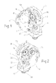
- the device is divided on the central longitudinal plane in a front housing shell 1 and in a rear housing shell 2.
- An electric motor 3 is attached to a flange 4 of the device.
- Each one in the housing shells 1 and 2 integrated stripper 5 has a cover 5a with a central opening, which covers the milling heads 25 of the peeling to the outside.
- the device is oriented horizontally, with the axes of the pullers and the milling device then being aligned vertically.
- the electric motor 4 drives coaxially a worm shaft 7.
- the worm shaft drives spur gears 9, 10 and 11 and finally a spur gear 12 of lying in the front housing shell 1 puller 5.
- the spur gear 11 is not on a Shaft shown connected to a same spur gear in the rear housing shell 2, which is in engagement with the ring gear of the arranged in the rear housing shell 2 second peeling device 5.
- the spur gears 12 run in the two housing shells in opposite directions of rotation.
- a bevel gear 13 is arranged, which is in engagement with a large bevel gear 14 of the milling device 6.
- each stripper 5 has a peel head 16, both of which are coaxially arranged in the housing shells 1 and 2 so as to face each other at a distance from each other.
- the robot's welding gun may, with simultaneous alignment with the peel heads, move sideways the one electrode cap for removal from the electrode cap receptacle 24 into one peel head 16 and thereafter insert the other electrode cap for peeling into the other peel head 16 with an opposite sideward movement.
- a cap-discharge channel 17 which has a lying in the housing shell 2 cap outlet 17a, to which a discharge hose, not shown, is connected.
- this repulsion bracket 18 may be replaced by a spring-loaded pin which protrudes correspondingly against the common axis of the two Abziehkexcellent 16.
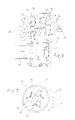
- Fig. 7 shows an enlarged schematic view of the essential structure of the two spur gears 12 of the peeling 5.
- An inserted into the central opening 15 of the spur gear 12 electrode cap is denoted by 20.
- two clamping jaws 22 are mounted on both sides projecting pin 22 at equal angular intervals from each other pivotally.
- Each jaw 22 is loaded with a tension spring 23 in the direction of the electrode cap 20. If the ring gear 12 pivots in a clockwise direction (arrow A), then the tension springs 23 pull the clamping jaws 22 against the electrode cap 20, which thus becomes increasingly firmly gripped and can then be pulled off the welding tongs.
- the electrode cap is inserted in stationary gear in the stripping device 5. Then the engine 3 starts and after one to two revolutions is stopped. The electrode cap is loosened in its seat and the welding robot moves the welding gun with the electrode cap receptacle 24 out of the electrode cap. The withdrawn electrode cap remains in the stripper and is pushed in a subsequent stripping process by the following cap in the discharge channel 17. When pushed the cap abuts the sprung obliquely shaped Abillonbügel 18, which deflects the cap toward the channel exit. An elevator disc hurls the cap pushed away from the push bar in the direction of the channel exit. This elevator disc is arranged on the inside of one of the two spur wheels 12. It has two elevator wings 33 (FIG. Fig. 6 ).
- the elevator vanes 33 rotate with each stripping operation and eject the withdrawn caps outwardly into the discharge channel 17, thereby preventing the caps from remaining on the stripping head. This is particularly advantageous in the horizontal position of the stripper. In the vertical position of the peeling the caps always fall down into the discharge channel 17th
- the two Abziehkexcellent 16 rotate in opposite directions.
- the one puller has a clockwise rotation
- the other puller also has a clockwise rotation.
- the possibly screwed electrode cap receptacles 24 of the welding gun are not loosened.
- Fig. 8 shows the milling device 6 in a simplified sectional view.
- the bevel gear pinion 13 is engaged with the bevel gear 14, with which the milling head 25 is drivingly connected.
- chips receiving chambers 26 On both sides of the milling head 25 are chips receiving chambers 26 which open into a common chip discharge channel 27 having at the free end a connecting piece 28 which can be connected via a discharge hose with a suction device.
- Each receiving chamber 26 is associated with a compressed air nozzle, not shown, which presses the chips in the discharge channel 27.
- Two compressed air connections are designated 36 and 37 ( Fig. 4 ).
- the milling device 6 can be covered with a transparent, elastic film cap 29 which has electrode cap through-openings and which is fastened with screws 30.
- a viewing window 34 is arranged in the region of the stripping device 5, which is covered with a transparent cap 35 ( Fig. 3 and 2 ).
Landscapes
- Engineering & Computer Science (AREA)
- Mechanical Engineering (AREA)
- Electrical Discharge Machining, Electrochemical Machining, And Combined Machining (AREA)
- Automatic Assembly (AREA)
- Resistance Welding (AREA)
Priority Applications (1)
| Application Number | Priority Date | Filing Date | Title |
|---|---|---|---|
| EP15172823.5A EP2960003A1 (fr) | 2012-03-15 | 2013-03-14 | Dispositif d'enlèvement d'embouts d'électrodes sur des robots de soudage |
Applications Claiming Priority (1)
| Application Number | Priority Date | Filing Date | Title |
|---|---|---|---|
| DE201210005259 DE102012005259A1 (de) | 2012-03-15 | 2012-03-15 | Kombinierte Vorrichtung zum mechanischen Bearbeiten und Entfernen von Elektrodenkappen an Schweißrobotern |
Related Child Applications (1)
| Application Number | Title | Priority Date | Filing Date |
|---|---|---|---|
| EP15172823.5A Division EP2960003A1 (fr) | 2012-03-15 | 2013-03-14 | Dispositif d'enlèvement d'embouts d'électrodes sur des robots de soudage |
Publications (2)
| Publication Number | Publication Date |
|---|---|
| EP2639005A2 true EP2639005A2 (fr) | 2013-09-18 |
| EP2639005A3 EP2639005A3 (fr) | 2013-11-20 |
Family
ID=47901785
Family Applications (2)
| Application Number | Title | Priority Date | Filing Date |
|---|---|---|---|
| EP13159105.9A Withdrawn EP2639005A3 (fr) | 2012-03-15 | 2013-03-14 | Dispositif combiné de traitement mécanique et d'enlèvement d'embouts d'électrodes sur des robots de soudage |
| EP15172823.5A Withdrawn EP2960003A1 (fr) | 2012-03-15 | 2013-03-14 | Dispositif d'enlèvement d'embouts d'électrodes sur des robots de soudage |
Family Applications After (1)
| Application Number | Title | Priority Date | Filing Date |
|---|---|---|---|
| EP15172823.5A Withdrawn EP2960003A1 (fr) | 2012-03-15 | 2013-03-14 | Dispositif d'enlèvement d'embouts d'électrodes sur des robots de soudage |
Country Status (2)
| Country | Link |
|---|---|
| EP (2) | EP2639005A3 (fr) |
| DE (2) | DE102012005259A1 (fr) |
Cited By (5)
| Publication number | Priority date | Publication date | Assignee | Title |
|---|---|---|---|---|
| CN103770070A (zh) * | 2013-11-14 | 2014-05-07 | 浙江吉利控股集团有限公司 | 一种用于拆卸焊接电极头的工具 |
| CN104801973A (zh) * | 2015-04-29 | 2015-07-29 | 广州市极动焊接机械有限公司 | 一种电极帽自动拆装修磨一体设备 |
| WO2016088056A1 (fr) * | 2014-12-04 | 2016-06-09 | Sinterleghe S.R.L. | Mécanisme pour libérer des capuchons d'électrode à partir d'un pistolet de soudage par points |
| CN107107245A (zh) * | 2015-09-15 | 2017-08-29 | 拓迈焊接机电设备有限公司 | 旋转更换装置 |
| EP3785840A1 (fr) * | 2019-08-29 | 2021-03-03 | Lutz Precision, K.S. | Dispositif et procédé de serrage et de retenue d'un capuchon d'électrode et de dévissage du capuchon d'électrode à partir du logement des capuchons d'électrode |
Families Citing this family (5)
| Publication number | Priority date | Publication date | Assignee | Title |
|---|---|---|---|---|
| WO2015118573A1 (fr) * | 2014-02-06 | 2015-08-13 | 株式会社キョクトー | Dispositif de travail rotatif |
| DE102014209828A1 (de) * | 2014-05-23 | 2015-11-26 | Lutz Technologies S.R.O. | Abziehwerkzeug zum Abziehen von Elektrodenkappen von Kappenträgern von Punktschweißelektroden |
| DE202015009336U1 (de) * | 2015-03-16 | 2017-03-06 | Lutz Technologies S.R.O. | Abzieheinheit zum Abziehen der Elektrodenkappen von Kappenträgern eines Paares von Punktschweißelektroden |
| EP3766621A1 (fr) * | 2019-07-15 | 2021-01-20 | Lutz Precision, K.S. | Dispositif permettant de dévisser et de détacher un capuchon d'électrode d'un dispositif de réception des capuchons d'électrode et dispositif de détachement |
| CN112809163B (zh) * | 2021-01-17 | 2022-11-22 | 东莞市飞越激光设备有限公司 | 一种激光切割圆形材料固定切割方法 |
Citations (5)
| Publication number | Priority date | Publication date | Assignee | Title |
|---|---|---|---|---|
| EP1287938A1 (fr) * | 2000-05-26 | 2003-03-05 | Kyokutoh Company | Dispositif de traitement et d'enlèvement d'embouts d'électrodes de soudage |
| DE102006041264A1 (de) * | 2006-09-02 | 2008-10-02 | Pst Lutz Technik Gmbh | Elektrodenkappenfräs- und Wechseleinrichtung |
| EP2002911A1 (fr) * | 2007-06-14 | 2008-12-17 | Beko GmbH | Tête d'usinage, notamment pour le fraisage d'électrodes, dispositif d'enlèvement de copeaux, ainsi q'une unité constituée d'une tête d'usinage et un dispositif d'enlèvement de copeaux. |
| DE202009004834U1 (de) * | 2009-05-20 | 2009-07-23 | Kaeseler, Werner | Fräser-Wechsler-Kombination für Schweisskappen |
| DE202009017079U1 (de) * | 2009-12-17 | 2010-03-18 | Schweißtechnik Bräuer GmbH | Elektrokappenfräs- und -abzieheinrichtung |
Family Cites Families (3)
| Publication number | Priority date | Publication date | Assignee | Title |
|---|---|---|---|---|
| FR2760391B1 (fr) * | 1997-03-06 | 1999-07-16 | Roger Louzier | Dispositif pour l'entretien des automates programmables |
| JP3680154B2 (ja) * | 1998-07-01 | 2005-08-10 | 株式会社キョクトー | 電極チップの抜き取り装置 |
| DE202011105419U1 (de) * | 2011-07-13 | 2011-11-16 | REU-Schweißtechnik GmbH | Vorrichtung zum Abheben einer Elektrodenkappe |
-
2012
- 2012-03-15 DE DE201210005259 patent/DE102012005259A1/de not_active Withdrawn
-
2013
- 2013-03-14 EP EP13159105.9A patent/EP2639005A3/fr not_active Withdrawn
- 2013-03-14 EP EP15172823.5A patent/EP2960003A1/fr not_active Withdrawn
- 2013-03-14 DE DE202013012196.3U patent/DE202013012196U1/de not_active Expired - Lifetime
Patent Citations (5)
| Publication number | Priority date | Publication date | Assignee | Title |
|---|---|---|---|---|
| EP1287938A1 (fr) * | 2000-05-26 | 2003-03-05 | Kyokutoh Company | Dispositif de traitement et d'enlèvement d'embouts d'électrodes de soudage |
| DE102006041264A1 (de) * | 2006-09-02 | 2008-10-02 | Pst Lutz Technik Gmbh | Elektrodenkappenfräs- und Wechseleinrichtung |
| EP2002911A1 (fr) * | 2007-06-14 | 2008-12-17 | Beko GmbH | Tête d'usinage, notamment pour le fraisage d'électrodes, dispositif d'enlèvement de copeaux, ainsi q'une unité constituée d'une tête d'usinage et un dispositif d'enlèvement de copeaux. |
| DE202009004834U1 (de) * | 2009-05-20 | 2009-07-23 | Kaeseler, Werner | Fräser-Wechsler-Kombination für Schweisskappen |
| DE202009017079U1 (de) * | 2009-12-17 | 2010-03-18 | Schweißtechnik Bräuer GmbH | Elektrokappenfräs- und -abzieheinrichtung |
Cited By (13)
| Publication number | Priority date | Publication date | Assignee | Title |
|---|---|---|---|---|
| CN103770070A (zh) * | 2013-11-14 | 2014-05-07 | 浙江吉利控股集团有限公司 | 一种用于拆卸焊接电极头的工具 |
| US20180264582A1 (en) * | 2014-12-04 | 2018-09-20 | Sinterleghe S.r.l | Mechanism for releasing electrode caps from a spot welding gun |
| US10737350B2 (en) * | 2014-12-04 | 2020-08-11 | Sinterleghe S.r.l | Mechanism for releasing electrode caps from a spot welding gun |
| WO2016088056A1 (fr) * | 2014-12-04 | 2016-06-09 | Sinterleghe S.R.L. | Mécanisme pour libérer des capuchons d'électrode à partir d'un pistolet de soudage par points |
| CN107206537B (zh) * | 2014-12-04 | 2019-11-22 | 希特丽格有限责任公司 | 用于从点焊枪释放电极帽的释放机构 |
| CN107206537A (zh) * | 2014-12-04 | 2017-09-26 | 希特丽格有限责任公司 | 用于从点焊枪释放电极帽的释放机构 |
| CN104801973B (zh) * | 2015-04-29 | 2017-06-20 | 广州市极动焊接机械有限公司 | 一种电极帽自动拆装修磨一体设备 |
| CN104801973A (zh) * | 2015-04-29 | 2015-07-29 | 广州市极动焊接机械有限公司 | 一种电极帽自动拆装修磨一体设备 |
| EP3205436A4 (fr) * | 2015-09-15 | 2018-01-17 | Tipman Co., Ltd. | Dispositif de remplacement rotatif |
| CN107107245B (zh) * | 2015-09-15 | 2019-06-07 | 拓迈焊接机电设备有限公司 | 旋转更换装置 |
| CN107107245A (zh) * | 2015-09-15 | 2017-08-29 | 拓迈焊接机电设备有限公司 | 旋转更换装置 |
| US10730136B2 (en) | 2015-09-15 | 2020-08-04 | Tipman Co., Ltd. | Rotary changer |
| EP3785840A1 (fr) * | 2019-08-29 | 2021-03-03 | Lutz Precision, K.S. | Dispositif et procédé de serrage et de retenue d'un capuchon d'électrode et de dévissage du capuchon d'électrode à partir du logement des capuchons d'électrode |
Also Published As
| Publication number | Publication date |
|---|---|
| EP2639005A3 (fr) | 2013-11-20 |
| DE102012005259A1 (de) | 2013-09-19 |
| EP2960003A1 (fr) | 2015-12-30 |
| DE202013012196U1 (de) | 2015-08-03 |
Similar Documents
| Publication | Publication Date | Title |
|---|---|---|
| EP2639005A2 (fr) | Dispositif combiné de traitement mécanique et d'enlèvement d'embouts d'électrodes sur des robots de soudage | |
| DE3038489C2 (de) | Handwerkzeugmaschine mit einem rotierend angetriebenen Werkzeug | |
| DE102010019852A1 (de) | Vorrichtung zum Schleifen von Handmessern | |
| EP0534106B1 (fr) | Dispositif pour appliquer des manchons sur câbles électriques | |
| DE202018100760U1 (de) | Zweihändig bedienbare Schleifmaschine | |
| EP3000559B1 (fr) | Machine-outil et sa structure porteuse | |
| DE4418603A1 (de) | Drahtführungsvorrichtung für eine einen Lichtbogen erzeugende elektrische Maschine mit Drahtelektroden | |
| DE10303400B4 (de) | Schlagwerkzeug | |
| DE102015105259B4 (de) | Werkzeugwechsler für eine Werkzeugmaschine | |
| EP2384980A1 (fr) | Station de travail pour machine d'emballage | |
| DE1729164B1 (de) | Vorrichtung zum automatischen abtrennen des angusses bzw. der anguesse von auf einer spritzgussmaschine hergestellten diapositiv-rahmen bzw. rahmenhaelften und zum aufreihen derselben auf transportstaebe | |
| DE202014105294U1 (de) | Schneidvorrichtung für Taschenfederstreifen | |
| DE102010045702A1 (de) | Faserschneidvorrichtung | |
| EP1779934B1 (fr) | Dispositif d'aspiration d'une zone de la paroi d'un alésage de moyeu de roues de véhicule revêtues de poudre | |
| DE102006061635A1 (de) | Handgeführte Werkzeugmaschine | |
| AT523406B1 (de) | Zerkleinerungsmaschine | |
| DE102014002045A1 (de) | Fräsvorrichtung | |
| EP3209464B1 (fr) | Machine-outil portative pourvue d'un porte-outil sds | |
| EP1070374A1 (fr) | Dispositif et procede de denudage | |
| DE102015002502A1 (de) | Vorrichtung zum Wenden von formstabilen Behältern | |
| EP3505355A1 (fr) | Dispositif de découpage pour rouleaux étiquettes | |
| DE112014003381T5 (de) | Spannvorrichtung | |
| EP2382066A1 (fr) | Dispositif de guidage pour une fraise à main pour électrodes de soudage par points | |
| DE202012100512U1 (de) | Aus wenigstens drei Teilen bestehendes Luftpumpensystem | |
| CH710171B1 (de) | Werkzeugmaschine. |
Legal Events
| Date | Code | Title | Description |
|---|---|---|---|
| PUAI | Public reference made under article 153(3) epc to a published international application that has entered the european phase |
Free format text: ORIGINAL CODE: 0009012 |
|
| AK | Designated contracting states |
Kind code of ref document: A2 Designated state(s): AL AT BE BG CH CY CZ DE DK EE ES FI FR GB GR HR HU IE IS IT LI LT LU LV MC MK MT NL NO PL PT RO RS SE SI SK SM TR |
|
| AX | Request for extension of the european patent |
Extension state: BA ME |
|
| PUAL | Search report despatched |
Free format text: ORIGINAL CODE: 0009013 |
|
| AK | Designated contracting states |
Kind code of ref document: A3 Designated state(s): AL AT BE BG CH CY CZ DE DK EE ES FI FR GB GR HR HU IE IS IT LI LT LU LV MC MK MT NL NO PL PT RO RS SE SI SK SM TR |
|
| AX | Request for extension of the european patent |
Extension state: BA ME |
|
| RIC1 | Information provided on ipc code assigned before grant |
Ipc: B23K 11/30 20060101AFI20131017BHEP |
|
| 17P | Request for examination filed |
Effective date: 20131203 |
|
| RBV | Designated contracting states (corrected) |
Designated state(s): AL AT BE BG CH CY CZ DE DK EE ES FI FR GB GR HR HU IE IS IT LI LT LU LV MC MK MT NL NO PL PT RO RS SE SI SK SM TR |
|
| 17Q | First examination report despatched |
Effective date: 20140103 |
|
| STAA | Information on the status of an ep patent application or granted ep patent |
Free format text: STATUS: THE APPLICATION IS DEEMED TO BE WITHDRAWN |
|
| 18D | Application deemed to be withdrawn |
Effective date: 20161001 |