EP3000559B1 - Machine-outil et sa structure porteuse - Google Patents
Machine-outil et sa structure porteuse Download PDFInfo
- Publication number
- EP3000559B1 EP3000559B1 EP15177978.2A EP15177978A EP3000559B1 EP 3000559 B1 EP3000559 B1 EP 3000559B1 EP 15177978 A EP15177978 A EP 15177978A EP 3000559 B1 EP3000559 B1 EP 3000559B1
- Authority
- EP
- European Patent Office
- Prior art keywords
- tool
- machine tool
- articulation
- connection
- suction
- Prior art date
- Legal status (The legal status is an assumption and is not a legal conclusion. Google has not performed a legal analysis and makes no representation as to the accuracy of the status listed.)
- Active
Links
- 239000000428 dust Substances 0.000 claims description 14
- 238000000605 extraction Methods 0.000 claims description 6
- 239000002245 particle Substances 0.000 claims description 4
- 229920003023 plastic Polymers 0.000 claims description 3
- 239000004033 plastic Substances 0.000 claims description 3
- 239000000463 material Substances 0.000 claims 1
- 238000005299 abrasion Methods 0.000 description 3
- 230000005540 biological transmission Effects 0.000 description 3
- 230000007704 transition Effects 0.000 description 3
- 239000012530 fluid Substances 0.000 description 2
- 238000004519 manufacturing process Methods 0.000 description 2
- 238000007789 sealing Methods 0.000 description 2
- 238000004140 cleaning Methods 0.000 description 1
- 238000011109 contamination Methods 0.000 description 1
- 230000000694 effects Effects 0.000 description 1
- 230000003993 interaction Effects 0.000 description 1
- 238000003754 machining Methods 0.000 description 1
Images

Classifications
-
- B—PERFORMING OPERATIONS; TRANSPORTING
- B24—GRINDING; POLISHING
- B24B—MACHINES, DEVICES, OR PROCESSES FOR GRINDING OR POLISHING; DRESSING OR CONDITIONING OF ABRADING SURFACES; FEEDING OF GRINDING, POLISHING, OR LAPPING AGENTS
- B24B55/00—Safety devices for grinding or polishing machines; Accessories fitted to grinding or polishing machines for keeping tools or parts of the machine in good working condition
- B24B55/06—Dust extraction equipment on grinding or polishing machines
- B24B55/10—Dust extraction equipment on grinding or polishing machines specially designed for portable grinding machines, e.g. hand-guided
-
- B—PERFORMING OPERATIONS; TRANSPORTING
- B24—GRINDING; POLISHING
- B24B—MACHINES, DEVICES, OR PROCESSES FOR GRINDING OR POLISHING; DRESSING OR CONDITIONING OF ABRADING SURFACES; FEEDING OF GRINDING, POLISHING, OR LAPPING AGENTS
- B24B23/00—Portable grinding machines, e.g. hand-guided; Accessories therefor
- B24B23/02—Portable grinding machines, e.g. hand-guided; Accessories therefor with rotating grinding tools; Accessories therefor
-
- B—PERFORMING OPERATIONS; TRANSPORTING
- B24—GRINDING; POLISHING
- B24B—MACHINES, DEVICES, OR PROCESSES FOR GRINDING OR POLISHING; DRESSING OR CONDITIONING OF ABRADING SURFACES; FEEDING OF GRINDING, POLISHING, OR LAPPING AGENTS
- B24B55/00—Safety devices for grinding or polishing machines; Accessories fitted to grinding or polishing machines for keeping tools or parts of the machine in good working condition
- B24B55/06—Dust extraction equipment on grinding or polishing machines
- B24B55/10—Dust extraction equipment on grinding or polishing machines specially designed for portable grinding machines, e.g. hand-guided
- B24B55/102—Dust extraction equipment on grinding or polishing machines specially designed for portable grinding machines, e.g. hand-guided with rotating tools
-
- B—PERFORMING OPERATIONS; TRANSPORTING
- B24—GRINDING; POLISHING
- B24B—MACHINES, DEVICES, OR PROCESSES FOR GRINDING OR POLISHING; DRESSING OR CONDITIONING OF ABRADING SURFACES; FEEDING OF GRINDING, POLISHING, OR LAPPING AGENTS
- B24B7/00—Machines or devices designed for grinding plane surfaces on work, including polishing plane glass surfaces; Accessories therefor
- B24B7/10—Single-purpose machines or devices
- B24B7/18—Single-purpose machines or devices for grinding floorings, walls, ceilings or the like
- B24B7/182—Single-purpose machines or devices for grinding floorings, walls, ceilings or the like for walls and ceilings
- B24B7/184—Single-purpose machines or devices for grinding floorings, walls, ceilings or the like for walls and ceilings pole sanders
Definitions
- the invention relates to a machine tool according to claim 1.
- the invention relates to a grinding machine, comprising a drive unit for driving a connectable tool, a tool unit having a tool holder to which the connectable tool can be attached, and a dust cover in the tool holder, wherein the tool unit is attached to the machine tool by means of a support structure.
- the machine tool also has for the discharge of exhaust air and dust particles contained therein from the dust cover to a suction on an air duct.
- Air ducts within carrying structures of small or manually operated tools are well known, it is exemplary of the US Pat. No. 7,249,996 B1 directed.
- a machine tool according to the preamble of claim 1 is known from the document US 2004/180616 A1 known.
- a hand-held grinding apparatus is already known, which comprises a holding device for holding the grinding machine, a drive motor for driving a tool and a tool head for receiving the tool.
- the document discloses DE 10 2012 111 990 A1 a corresponding arrangement in which further comprises a hood device on the tool head, which covers the tool holder. Due to the arrangement of the tool holder and the tool in the hood space of the hood device occurring during operation of the grinding machine abrasion can be maintained within the tool head. Contamination of the environment of the grinding machine can be avoided thereby.
- a suction device is provided in order to be able to remove the abrasion occurring in the grinding operation of the grinding machine from the tool head.
- This comprises a suction channel which fluidly connects the hood space with a suction device which can be connected to a connecting device of the grinding machine.
- a flexible tube element is attached, which connects the hood housing with other sections of the suction channel and at the same time allows an articulated connection of the tool head with the rest of the machine body.
- an object of the present invention is to further develop the known from the prior art machine tool and at least to reduce the disadvantages known from practice.
- the at least one articulated connection has an air guide channel which extends through the articulated connection and is in fluid communication with a suction opening on the dust protection cover.
- the at least one articulated connection additionally draws in outside air into the air duct, thereby creating a quasi-self-cleaning joint, since no dirt particles can accumulate within the articulated connection as a result of the absorbed external air.
- the at least one hinge connection is made of plastic. As a result, a particularly simple and inexpensive to produce articulated connection is created.
- the at least one articulated connection can furthermore comprise at least one articulated body and at least two, preferably four articulated parts, which in pairs define the at least one, preferably two articulation axes and, by cooperation with the articulated body, enable rotatable mounting of the tool unit on the supporting structure.
- the joint body can be rotatably mounted on the joint parts in this embodiment, in particular, the joint parts rotatably receive or support a portion of the joint body.
- the support structure may comprise a connecting piece for connecting a separately formed suction device, in particular a Allessaugers.
- a separately formed suction device in particular a Allessaugers.
- the machine tool comprises a permanently attached to this suction device.
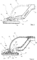
- the figures show a machine tool according to the invention, in particular its tool-side front portion, which is generally indicated by the reference numeral 10.
- the machine tool 10 is designed as a hand-held grinding machine, in particular as a long-necked sander, and comprises a tool unit (also called tool head) 12, a support structure 20 and a drive unit (not shown).
- the support structure 20 serves to hold the machine tool and connects the drive unit to the tool unit 12.
- the tool unit 12 is pivotally mounted at a distal end of the support structure 20 relative thereto.
- the tool unit 12 comprises in particular a hood device 14, which covers a tool holder 34b and a tool 36 received thereon of the tool unit 12.
- the hood device 14 is formed in the illustrated embodiment as a hood-shaped dust cover 14, which on a side facing the workpiece to be machined end comprises a sealing device which extends along a circumferential direction of the dust cover 14 and a sealing ring, in particular an annular brush ring 16 includes. This is how in the FIG. 3 represented relative to the dust cover 14 via a spring device 38 resiliently mounted, whereby a clean contact can be made to a surface to be machined.
- a hood space is formed, which serves to receive the resulting in the machining of a workpiece abrasion.
- the dust cover 14 also has suction openings 14a, in the region of which connecting sections 18 are provided, which mechanically and fluidically connect the dust cover 14 with a hinge connection 28.
- the support structure 20 of the present machine tool 10 comprises in the illustrated embodiment, a plurality of sections, namely a holding section or handle bar, a transition section 22 and a support fork or pivot fork 24, which has two support arms 26 for supporting the tool unit.
- a hinge connection 28 is provided between the connecting portions 18 of the dust cover 14 and the support arms 26 of the support fork 24, which due to their specific embodiment both a Pivoting the tool head 12 about two pivot axes A and B and a fluidic connection of the hood space with an air duct of the support structure 20 allows.
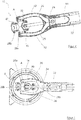
- the specific embodiment of the articulated connection 28 can be in particular also the FIGS. 3 to 5 remove.
- a joint body 28a Shown therein is a joint body 28a with a centrally tapered double cone, a thereto perpendicular, converging centrally with the double cone third cone and the third cone opposite fork structure, all of these elements are formed in the illustrated embodiment as interconnected with each other hollow body and together formed therein air duct 40.
- the joint body 28a is encompassed at free ends or its connection points in each case by annular joint parts 28b, wherein the joint body 28a is rotatably mounted with its connection points in each case within these annular genotype parts 28b.
- the joint body 28a as well as the joint parts 28b may be made of plastic, for example, which allows a particularly simple and cost-effective production of the joint.
- the joint parts 28b for rotatably receiving the joint body 28a may also be formed integrally with the connecting portions 18. However, a simpler production is made possible when the hinge parts 28b are formed separately, as shown in the figures.
- the joint body 28a allows by its interaction with the joint parts 28b in the manner of a universal joint pivoting of the tool unit 12 relative to the support structure 20 about the two axes of rotation A and B.
- the inner air duct 40 also the hood space within the hood-shaped dust cover 14 fluidly with the support structure 20 connected.
- the machine tool 10 further comprises a transmission shaft 32, which is at least partially guided within a tubular rod 30, which, like the transmission shaft 32, at least partially flexible. At its free end (distal end) 34a, the transmission shaft 32 drives the tool holder 34b, to which a tool 36 can be releasably attached.
- a machine tool in particular a long-necked sander, is provided, which takes less space in the region of its tool head than the known solutions do and is less susceptible to external damage.
- the functional combination of the support structure and the inclusion of a fluid channel for air guidance of the suction air a particularly simple and cost-effective solution is provided, the existing advantages of known solutions, without bringing their disadvantages with.
Landscapes
- Engineering & Computer Science (AREA)
- Mechanical Engineering (AREA)
- Grinding-Machine Dressing And Accessory Apparatuses (AREA)
- Finish Polishing, Edge Sharpening, And Grinding By Specific Grinding Devices (AREA)
- Constituent Portions Of Griding Lathes, Driving, Sensing And Control (AREA)
- Auxiliary Devices For Machine Tools (AREA)
Claims (7)
- Machine-outil (10) en particulier machine de ponçage, comportant :une unité d'entraînement pour assurer l'entraînement d'un outil connectable (36), une unité d'outillage (12) comportant un récepteur d'outil (34b), auquel l'outil connectable (36) peut être adapté, ainsi qu'une couverture de protection contre la poussière (14) dans le secteur du récepteur d'outil (34b), dans lequel l'unité d'outillage (12) est installée sur la machine-outil (10) au moyen d'une structure portante (20),ainsi qu'un canal de circulation d'air (40, 42, 44, 46) qui s'étend depuis la couverture de protection contre la poussière (14) jusqu'à une installation d'aspiration pour évacuer l'air d'aspiration ainsi que les particules de poussière qu'il contient, dans lequel le canal de circulation d'air (40, 42, 44, 46) est intégralement incorporé dans la structure portante (20) et dans lequel la structure portante (20) comporte au moins une liaison articulée (28), qui lie l'unité d'outillage (12) à la machine outil (10) de façon tournante autour d'au moins un axe (A, B), et de préférence autour de deux axes (A, B),caractérisée en ce que ladite au moins une liaison articulée (28) comporte des fentes dimensionnées de façon appropriées par rapport aux parties mobiles relativement entre elles de la liaison articulée ou complémentaires, de telle manière que au moins une liaison articulée (28) est capable d'aspirer de l'air extérieur supplémentaire dans le canal d'aération (40).
- Machine-outil (10) selon la revendication 1,
caractérisée en ce que la structure portante (20) de la machine-outil (10) comporte une tige de prise de contact à laquelle l'unité d'entrainement et l'unité d'outillage (12) sont fixées. - Machine-outil (10) selon les revendications 1 ou 2,
caractérisée en ce que la structure portante (20) comporte une fourche d'appui (24) avec au moins deux bras d'appui (26) pour soutenir l'unité d'outillage (12), dans lequel au moins un des bras d'appui (26) comporte un canal de conduite d'air (42) intégralement formé, qui se trouve en liaison fluidique avec une ouverture d'aspiration (14a) au niveau de la couverture de protection contre la poussière (14). - Machine-outil (10) selon l'une des revendications précédentes,
caractérisée en ce que ladite au moins une liaison articulée (28) comporte un canal de conduite d'air (40), qui s'étend à travers la liaison articulée (28) et se trouve en liaison fluidique avec une ouverture d'aspiration (14a) de la couverture de protection contre la poussière (14). - Machine-outil (10) selon l'une des revendications précédentes,
caractérisée en ce que ladite au moins une liaison articulée (28) est au moins partiellement réalisée en matière synthétique. - Machine-outil (10) selon l'une des revendications précédentes,
caractérisée en ce que ladite au moins une liaison articulée (28) comporte au moins un corps d'articulation (28a) ainsi qu'au moins deux, avantageusement quatre éléments d'articulations (28b) qui définissent par paire les axes (A, B) des articulations. - Machine-outil (10) selon l'une des revendications précédentes,
caractérisée en ce que la structure portante (20) comporte une butée d'arrêt pour arrêter une installation d'aspiration séparée, en particulier un aspirateur général.
Applications Claiming Priority (1)
| Application Number | Priority Date | Filing Date | Title |
|---|---|---|---|
| DE102014113881.3A DE102014113881A1 (de) | 2014-09-25 | 2014-09-25 | Werkzeugmaschine sowie Tragstruktur hierfür |
Publications (3)
| Publication Number | Publication Date |
|---|---|
| EP3000559A2 EP3000559A2 (fr) | 2016-03-30 |
| EP3000559A3 EP3000559A3 (fr) | 2016-04-06 |
| EP3000559B1 true EP3000559B1 (fr) | 2018-09-12 |
Family
ID=53886841
Family Applications (1)
| Application Number | Title | Priority Date | Filing Date |
|---|---|---|---|
| EP15177978.2A Active EP3000559B1 (fr) | 2014-09-25 | 2015-07-23 | Machine-outil et sa structure porteuse |
Country Status (2)
| Country | Link |
|---|---|
| EP (1) | EP3000559B1 (fr) |
| DE (1) | DE102014113881A1 (fr) |
Cited By (3)
| Publication number | Priority date | Publication date | Assignee | Title |
|---|---|---|---|---|
| US11919127B2 (en) | 2019-10-23 | 2024-03-05 | Black & Decker Inc. | Pole sander |
| US11951585B2 (en) | 2019-10-23 | 2024-04-09 | Black & Decker Inc. | Pole sander |
| US12005547B2 (en) | 2019-10-23 | 2024-06-11 | Black & Decker Inc. | Pole sander |
Families Citing this family (4)
| Publication number | Priority date | Publication date | Assignee | Title |
|---|---|---|---|---|
| EP3812093A1 (fr) * | 2019-10-23 | 2021-04-28 | Black & Decker Inc. | Ponceuse polaire |
| EP3812089A1 (fr) | 2019-10-23 | 2021-04-28 | Black & Decker Inc. | Ponceuse à manche |
| CN111958434A (zh) * | 2020-08-30 | 2020-11-20 | 陈维华 | 一种手持式机械加工用打磨装置 |
| US11867224B2 (en) | 2021-01-27 | 2024-01-09 | Black & Decker Inc. | Locking mechanism for two telescoping poles of a power tool |
Citations (1)
| Publication number | Priority date | Publication date | Assignee | Title |
|---|---|---|---|---|
| US20040180616A1 (en) * | 2003-03-11 | 2004-09-16 | Loveless Michael L. | Vacuum driven sander |
Family Cites Families (7)
| Publication number | Priority date | Publication date | Assignee | Title |
|---|---|---|---|---|
| US3826045A (en) * | 1973-09-14 | 1974-07-30 | Nat Detroit Inc | Abrading machine with dust collecting unit |
| US4759155A (en) * | 1987-03-06 | 1988-07-26 | Shaw Christopher J | Particle collecting sander |
| US5239783A (en) * | 1991-08-20 | 1993-08-31 | William Matechuk | Drywall sander |
| US7249996B1 (en) * | 2005-06-08 | 2007-07-31 | Mykhaylo Volyar | Vacuum sander |
| DE102008063508A1 (de) * | 2008-12-10 | 2010-06-17 | Flex-Elektrowerkzeuge Gmbh | Handgehaltene Reinigungs-/Schleifmaschine |
| ES2369582B1 (es) * | 2009-10-01 | 2012-11-06 | Reinaldo García Berenguer | Amoladora para reparación de carrocería con sistema de aspiración. |
| DE102012111990A1 (de) | 2012-12-07 | 2014-06-12 | Flex-Elektrowerkzeuge Gmbh | Handgehaltene Schleifmaschine |
-
2014
- 2014-09-25 DE DE102014113881.3A patent/DE102014113881A1/de not_active Ceased
-
2015
- 2015-07-23 EP EP15177978.2A patent/EP3000559B1/fr active Active
Patent Citations (1)
| Publication number | Priority date | Publication date | Assignee | Title |
|---|---|---|---|---|
| US20040180616A1 (en) * | 2003-03-11 | 2004-09-16 | Loveless Michael L. | Vacuum driven sander |
Cited By (3)
| Publication number | Priority date | Publication date | Assignee | Title |
|---|---|---|---|---|
| US11919127B2 (en) | 2019-10-23 | 2024-03-05 | Black & Decker Inc. | Pole sander |
| US11951585B2 (en) | 2019-10-23 | 2024-04-09 | Black & Decker Inc. | Pole sander |
| US12005547B2 (en) | 2019-10-23 | 2024-06-11 | Black & Decker Inc. | Pole sander |
Also Published As
| Publication number | Publication date |
|---|---|
| EP3000559A2 (fr) | 2016-03-30 |
| DE102014113881A1 (de) | 2016-03-31 |
| EP3000559A3 (fr) | 2016-04-06 |
Similar Documents
| Publication | Publication Date | Title |
|---|---|---|
| EP3000559B1 (fr) | Machine-outil et sa structure porteuse | |
| DE202014104588U1 (de) | Werkzeugmaschine sowie Tragstruktur hierfür | |
| EP3397392B1 (fr) | Pistolet pneumatique de nettoyage | |
| EP0470046B1 (fr) | Perceuse munie d'un aspirateur | |
| DE2813460C3 (de) | Rotierend angetriebenes Werkzeug mit Absauggehäuse | |
| DE102005058791B3 (de) | Zusatzgerät für Handbohrmaschinen zum Absaugen des beim Bohren entstehenden Staubes | |
| DE102007042667A1 (de) | Poliermaschine für Linsen und Verfahren zum Polieren einer Linse mit einer Bearbeitungsmaschine | |
| EP2960003A1 (fr) | Dispositif d'enlèvement d'embouts d'électrodes sur des robots de soudage | |
| EP3269504A1 (fr) | Capot d'aspiration pour machine-outil | |
| EP2140931B9 (fr) | Machine de mélange dotée d'une réception d'outil réglable en longueur | |
| DE202005007213U1 (de) | Düse für Bodenstaubsauger | |
| DE102006052807A1 (de) | Handwerkzeugmaschine mit einem vibrationsgedämpften Bügelhandgriff | |
| DE102006056854A1 (de) | Handwerkzeugmaschine mit schwenkbar angelengtem schwingungsisoliertem Handgriff | |
| EP3224433B1 (fr) | Machine de nettoyage immergée avec dispositif de déplacement | |
| DE1142681B (de) | Staubsaugermundstueck mit zwei gegeneinander beweglichen Werkzeugen | |
| DE4238245C2 (de) | Staubabsaugeinrichtung für ein als Handgerät ausgebildetes, motorisch angetriebenes Gerät | |
| DE3333177A1 (de) | Spanabhebendes werkzeug | |
| DE202021100353U1 (de) | Winkelkopf mit Anpassung des Positionierabstands und Positioniervorrichtung dafür | |
| DE202016104254U1 (de) | Zubehörgerät und dessen Kombination mit einem Kraftwerkzeug | |
| DE102007006498A1 (de) | Vorrichtung | |
| EP3145647B1 (fr) | Outil de nettoyage pour un bras robotique destiné à nettoyer des trous taraudés, des vis sans tête et des surfaces, entre autres au niveau de soubassements | |
| DE19821705A1 (de) | Sauggerät zum Ansaugen von Schmutz o. dgl. enthaltendem Sauggut | |
| EP1769883A1 (fr) | Dispositif pour nettoyage de la tige et de la surface de contact d'une machine outil | |
| EP3235602B1 (fr) | Dispositif de collecte de poussière comprenant un moyen de support | |
| EP3269503A1 (fr) | Capot d'aspiration comprenant une ouverture radiale d'insertion d'outil |
Legal Events
| Date | Code | Title | Description |
|---|---|---|---|
| PUAL | Search report despatched |
Free format text: ORIGINAL CODE: 0009013 |
|
| PUAI | Public reference made under article 153(3) epc to a published international application that has entered the european phase |
Free format text: ORIGINAL CODE: 0009012 |
|
| AK | Designated contracting states |
Kind code of ref document: A2 Designated state(s): AL AT BE BG CH CY CZ DE DK EE ES FI FR GB GR HR HU IE IS IT LI LT LU LV MC MK MT NL NO PL PT RO RS SE SI SK SM TR |
|
| AX | Request for extension of the european patent |
Extension state: BA ME |
|
| AK | Designated contracting states |
Kind code of ref document: A3 Designated state(s): AL AT BE BG CH CY CZ DE DK EE ES FI FR GB GR HR HU IE IS IT LI LT LU LV MC MK MT NL NO PL PT RO RS SE SI SK SM TR |
|
| AX | Request for extension of the european patent |
Extension state: BA ME |
|
| RIC1 | Information provided on ipc code assigned before grant |
Ipc: B24B 55/10 20060101AFI20160301BHEP Ipc: B24B 7/00 20060101ALI20160301BHEP Ipc: B24B 7/18 20060101ALI20160301BHEP Ipc: B24B 23/02 20060101ALI20160301BHEP |
|
| 17P | Request for examination filed |
Effective date: 20160916 |
|
| RBV | Designated contracting states (corrected) |
Designated state(s): AL AT BE BG CH CY CZ DE DK EE ES FI FR GB GR HR HU IE IS IT LI LT LU LV MC MK MT NL NO PL PT RO RS SE SI SK SM TR |
|
| STAA | Information on the status of an ep patent application or granted ep patent |
Free format text: STATUS: EXAMINATION IS IN PROGRESS |
|
| 17Q | First examination report despatched |
Effective date: 20170328 |
|
| GRAP | Despatch of communication of intention to grant a patent |
Free format text: ORIGINAL CODE: EPIDOSNIGR1 |
|
| STAA | Information on the status of an ep patent application or granted ep patent |
Free format text: STATUS: GRANT OF PATENT IS INTENDED |
|
| INTG | Intention to grant announced |
Effective date: 20171215 |
|
| GRAJ | Information related to disapproval of communication of intention to grant by the applicant or resumption of examination proceedings by the epo deleted |
Free format text: ORIGINAL CODE: EPIDOSDIGR1 |
|
| STAA | Information on the status of an ep patent application or granted ep patent |
Free format text: STATUS: EXAMINATION IS IN PROGRESS |
|
| INTC | Intention to grant announced (deleted) | ||
| GRAP | Despatch of communication of intention to grant a patent |
Free format text: ORIGINAL CODE: EPIDOSNIGR1 |
|
| STAA | Information on the status of an ep patent application or granted ep patent |
Free format text: STATUS: GRANT OF PATENT IS INTENDED |
|
| INTG | Intention to grant announced |
Effective date: 20180417 |
|
| GRAS | Grant fee paid |
Free format text: ORIGINAL CODE: EPIDOSNIGR3 |
|
| GRAA | (expected) grant |
Free format text: ORIGINAL CODE: 0009210 |
|
| STAA | Information on the status of an ep patent application or granted ep patent |
Free format text: STATUS: THE PATENT HAS BEEN GRANTED |
|
| AK | Designated contracting states |
Kind code of ref document: B1 Designated state(s): AL AT BE BG CH CY CZ DE DK EE ES FI FR GB GR HR HU IE IS IT LI LT LU LV MC MK MT NL NO PL PT RO RS SE SI SK SM TR |
|
| REG | Reference to a national code |
Ref country code: GB Ref legal event code: FG4D Free format text: NOT ENGLISH |
|
| REG | Reference to a national code |
Ref country code: CH Ref legal event code: EP |
|
| REG | Reference to a national code |
Ref country code: IE Ref legal event code: FG4D Free format text: LANGUAGE OF EP DOCUMENT: GERMAN |
|
| REG | Reference to a national code |
Ref country code: DE Ref legal event code: R096 Ref document number: 502015005810 Country of ref document: DE |
|
| REG | Reference to a national code |
Ref country code: AT Ref legal event code: REF Ref document number: 1039983 Country of ref document: AT Kind code of ref document: T Effective date: 20181015 |
|
| REG | Reference to a national code |
Ref country code: NL Ref legal event code: MP Effective date: 20180912 |
|
| REG | Reference to a national code |
Ref country code: LT Ref legal event code: MG4D |
|
| PG25 | Lapsed in a contracting state [announced via postgrant information from national office to epo] |
Ref country code: FI Free format text: LAPSE BECAUSE OF FAILURE TO SUBMIT A TRANSLATION OF THE DESCRIPTION OR TO PAY THE FEE WITHIN THE PRESCRIBED TIME-LIMIT Effective date: 20180912 Ref country code: GR Free format text: LAPSE BECAUSE OF FAILURE TO SUBMIT A TRANSLATION OF THE DESCRIPTION OR TO PAY THE FEE WITHIN THE PRESCRIBED TIME-LIMIT Effective date: 20181213 Ref country code: RS Free format text: LAPSE BECAUSE OF FAILURE TO SUBMIT A TRANSLATION OF THE DESCRIPTION OR TO PAY THE FEE WITHIN THE PRESCRIBED TIME-LIMIT Effective date: 20180912 Ref country code: SE Free format text: LAPSE BECAUSE OF FAILURE TO SUBMIT A TRANSLATION OF THE DESCRIPTION OR TO PAY THE FEE WITHIN THE PRESCRIBED TIME-LIMIT Effective date: 20180912 Ref country code: NO Free format text: LAPSE BECAUSE OF FAILURE TO SUBMIT A TRANSLATION OF THE DESCRIPTION OR TO PAY THE FEE WITHIN THE PRESCRIBED TIME-LIMIT Effective date: 20181212 Ref country code: LT Free format text: LAPSE BECAUSE OF FAILURE TO SUBMIT A TRANSLATION OF THE DESCRIPTION OR TO PAY THE FEE WITHIN THE PRESCRIBED TIME-LIMIT Effective date: 20180912 Ref country code: BG Free format text: LAPSE BECAUSE OF FAILURE TO SUBMIT A TRANSLATION OF THE DESCRIPTION OR TO PAY THE FEE WITHIN THE PRESCRIBED TIME-LIMIT Effective date: 20181212 |
|
| PG25 | Lapsed in a contracting state [announced via postgrant information from national office to epo] |
Ref country code: AL Free format text: LAPSE BECAUSE OF FAILURE TO SUBMIT A TRANSLATION OF THE DESCRIPTION OR TO PAY THE FEE WITHIN THE PRESCRIBED TIME-LIMIT Effective date: 20180912 Ref country code: HR Free format text: LAPSE BECAUSE OF FAILURE TO SUBMIT A TRANSLATION OF THE DESCRIPTION OR TO PAY THE FEE WITHIN THE PRESCRIBED TIME-LIMIT Effective date: 20180912 Ref country code: LV Free format text: LAPSE BECAUSE OF FAILURE TO SUBMIT A TRANSLATION OF THE DESCRIPTION OR TO PAY THE FEE WITHIN THE PRESCRIBED TIME-LIMIT Effective date: 20180912 |
|
| PG25 | Lapsed in a contracting state [announced via postgrant information from national office to epo] |
Ref country code: IS Free format text: LAPSE BECAUSE OF FAILURE TO SUBMIT A TRANSLATION OF THE DESCRIPTION OR TO PAY THE FEE WITHIN THE PRESCRIBED TIME-LIMIT Effective date: 20190112 Ref country code: NL Free format text: LAPSE BECAUSE OF FAILURE TO SUBMIT A TRANSLATION OF THE DESCRIPTION OR TO PAY THE FEE WITHIN THE PRESCRIBED TIME-LIMIT Effective date: 20180912 Ref country code: PL Free format text: LAPSE BECAUSE OF FAILURE TO SUBMIT A TRANSLATION OF THE DESCRIPTION OR TO PAY THE FEE WITHIN THE PRESCRIBED TIME-LIMIT Effective date: 20180912 Ref country code: CZ Free format text: LAPSE BECAUSE OF FAILURE TO SUBMIT A TRANSLATION OF THE DESCRIPTION OR TO PAY THE FEE WITHIN THE PRESCRIBED TIME-LIMIT Effective date: 20180912 Ref country code: ES Free format text: LAPSE BECAUSE OF FAILURE TO SUBMIT A TRANSLATION OF THE DESCRIPTION OR TO PAY THE FEE WITHIN THE PRESCRIBED TIME-LIMIT Effective date: 20180912 Ref country code: IT Free format text: LAPSE BECAUSE OF FAILURE TO SUBMIT A TRANSLATION OF THE DESCRIPTION OR TO PAY THE FEE WITHIN THE PRESCRIBED TIME-LIMIT Effective date: 20180912 Ref country code: RO Free format text: LAPSE BECAUSE OF FAILURE TO SUBMIT A TRANSLATION OF THE DESCRIPTION OR TO PAY THE FEE WITHIN THE PRESCRIBED TIME-LIMIT Effective date: 20180912 Ref country code: EE Free format text: LAPSE BECAUSE OF FAILURE TO SUBMIT A TRANSLATION OF THE DESCRIPTION OR TO PAY THE FEE WITHIN THE PRESCRIBED TIME-LIMIT Effective date: 20180912 |
|
| PG25 | Lapsed in a contracting state [announced via postgrant information from national office to epo] |
Ref country code: SM Free format text: LAPSE BECAUSE OF FAILURE TO SUBMIT A TRANSLATION OF THE DESCRIPTION OR TO PAY THE FEE WITHIN THE PRESCRIBED TIME-LIMIT Effective date: 20180912 Ref country code: PT Free format text: LAPSE BECAUSE OF FAILURE TO SUBMIT A TRANSLATION OF THE DESCRIPTION OR TO PAY THE FEE WITHIN THE PRESCRIBED TIME-LIMIT Effective date: 20190112 Ref country code: SK Free format text: LAPSE BECAUSE OF FAILURE TO SUBMIT A TRANSLATION OF THE DESCRIPTION OR TO PAY THE FEE WITHIN THE PRESCRIBED TIME-LIMIT Effective date: 20180912 |
|
| REG | Reference to a national code |
Ref country code: DE Ref legal event code: R097 Ref document number: 502015005810 Country of ref document: DE |
|
| PLBE | No opposition filed within time limit |
Free format text: ORIGINAL CODE: 0009261 |
|
| STAA | Information on the status of an ep patent application or granted ep patent |
Free format text: STATUS: NO OPPOSITION FILED WITHIN TIME LIMIT |
|
| PG25 | Lapsed in a contracting state [announced via postgrant information from national office to epo] |
Ref country code: DK Free format text: LAPSE BECAUSE OF FAILURE TO SUBMIT A TRANSLATION OF THE DESCRIPTION OR TO PAY THE FEE WITHIN THE PRESCRIBED TIME-LIMIT Effective date: 20180912 |
|
| 26N | No opposition filed |
Effective date: 20190613 |
|
| PG25 | Lapsed in a contracting state [announced via postgrant information from national office to epo] |
Ref country code: SI Free format text: LAPSE BECAUSE OF FAILURE TO SUBMIT A TRANSLATION OF THE DESCRIPTION OR TO PAY THE FEE WITHIN THE PRESCRIBED TIME-LIMIT Effective date: 20180912 |
|
| PG25 | Lapsed in a contracting state [announced via postgrant information from national office to epo] |
Ref country code: MC Free format text: LAPSE BECAUSE OF FAILURE TO SUBMIT A TRANSLATION OF THE DESCRIPTION OR TO PAY THE FEE WITHIN THE PRESCRIBED TIME-LIMIT Effective date: 20180912 |
|
| REG | Reference to a national code |
Ref country code: CH Ref legal event code: PL |
|
| PG25 | Lapsed in a contracting state [announced via postgrant information from national office to epo] |
Ref country code: TR Free format text: LAPSE BECAUSE OF FAILURE TO SUBMIT A TRANSLATION OF THE DESCRIPTION OR TO PAY THE FEE WITHIN THE PRESCRIBED TIME-LIMIT Effective date: 20180912 |
|
| REG | Reference to a national code |
Ref country code: BE Ref legal event code: MM Effective date: 20190731 |
|
| PG25 | Lapsed in a contracting state [announced via postgrant information from national office to epo] |
Ref country code: BE Free format text: LAPSE BECAUSE OF NON-PAYMENT OF DUE FEES Effective date: 20190731 Ref country code: CH Free format text: LAPSE BECAUSE OF NON-PAYMENT OF DUE FEES Effective date: 20190731 Ref country code: LU Free format text: LAPSE BECAUSE OF NON-PAYMENT OF DUE FEES Effective date: 20190723 Ref country code: LI Free format text: LAPSE BECAUSE OF NON-PAYMENT OF DUE FEES Effective date: 20190731 |
|
| PG25 | Lapsed in a contracting state [announced via postgrant information from national office to epo] |
Ref country code: IE Free format text: LAPSE BECAUSE OF NON-PAYMENT OF DUE FEES Effective date: 20190723 |
|
| PG25 | Lapsed in a contracting state [announced via postgrant information from national office to epo] |
Ref country code: CY Free format text: LAPSE BECAUSE OF FAILURE TO SUBMIT A TRANSLATION OF THE DESCRIPTION OR TO PAY THE FEE WITHIN THE PRESCRIBED TIME-LIMIT Effective date: 20180912 |
|
| PG25 | Lapsed in a contracting state [announced via postgrant information from national office to epo] |
Ref country code: HU Free format text: LAPSE BECAUSE OF FAILURE TO SUBMIT A TRANSLATION OF THE DESCRIPTION OR TO PAY THE FEE WITHIN THE PRESCRIBED TIME-LIMIT; INVALID AB INITIO Effective date: 20150723 Ref country code: MT Free format text: LAPSE BECAUSE OF FAILURE TO SUBMIT A TRANSLATION OF THE DESCRIPTION OR TO PAY THE FEE WITHIN THE PRESCRIBED TIME-LIMIT Effective date: 20180912 |
|
| REG | Reference to a national code |
Ref country code: AT Ref legal event code: MM01 Ref document number: 1039983 Country of ref document: AT Kind code of ref document: T Effective date: 20200723 |
|
| PG25 | Lapsed in a contracting state [announced via postgrant information from national office to epo] |
Ref country code: AT Free format text: LAPSE BECAUSE OF NON-PAYMENT OF DUE FEES Effective date: 20200723 |
|
| PG25 | Lapsed in a contracting state [announced via postgrant information from national office to epo] |
Ref country code: MK Free format text: LAPSE BECAUSE OF FAILURE TO SUBMIT A TRANSLATION OF THE DESCRIPTION OR TO PAY THE FEE WITHIN THE PRESCRIBED TIME-LIMIT Effective date: 20180912 |
|
| P01 | Opt-out of the competence of the unified patent court (upc) registered |
Effective date: 20230513 |
|
| PGFP | Annual fee paid to national office [announced via postgrant information from national office to epo] |
Ref country code: DE Payment date: 20240719 Year of fee payment: 10 |
|
| PGFP | Annual fee paid to national office [announced via postgrant information from national office to epo] |
Ref country code: GB Payment date: 20240723 Year of fee payment: 10 |
|
| PGFP | Annual fee paid to national office [announced via postgrant information from national office to epo] |
Ref country code: FR Payment date: 20240724 Year of fee payment: 10 |