EP3000559B1 - Machine tool and support structure therefor - Google Patents
Machine tool and support structure therefor Download PDFInfo
- Publication number
- EP3000559B1 EP3000559B1 EP15177978.2A EP15177978A EP3000559B1 EP 3000559 B1 EP3000559 B1 EP 3000559B1 EP 15177978 A EP15177978 A EP 15177978A EP 3000559 B1 EP3000559 B1 EP 3000559B1
- Authority
- EP
- European Patent Office
- Prior art keywords
- tool
- machine tool
- articulation
- connection
- suction
- Prior art date
- Legal status (The legal status is an assumption and is not a legal conclusion. Google has not performed a legal analysis and makes no representation as to the accuracy of the status listed.)
- Active
Links
Images

Classifications
-
- B—PERFORMING OPERATIONS; TRANSPORTING
- B24—GRINDING; POLISHING
- B24B—MACHINES, DEVICES, OR PROCESSES FOR GRINDING OR POLISHING; DRESSING OR CONDITIONING OF ABRADING SURFACES; FEEDING OF GRINDING, POLISHING, OR LAPPING AGENTS
- B24B55/00—Safety devices for grinding or polishing machines; Accessories fitted to grinding or polishing machines for keeping tools or parts of the machine in good working condition
- B24B55/06—Dust extraction equipment on grinding or polishing machines
- B24B55/10—Dust extraction equipment on grinding or polishing machines specially designed for portable grinding machines, e.g. hand-guided
-
- B—PERFORMING OPERATIONS; TRANSPORTING
- B24—GRINDING; POLISHING
- B24B—MACHINES, DEVICES, OR PROCESSES FOR GRINDING OR POLISHING; DRESSING OR CONDITIONING OF ABRADING SURFACES; FEEDING OF GRINDING, POLISHING, OR LAPPING AGENTS
- B24B23/00—Portable grinding machines, e.g. hand-guided; Accessories therefor
- B24B23/02—Portable grinding machines, e.g. hand-guided; Accessories therefor with rotating grinding tools; Accessories therefor
-
- B—PERFORMING OPERATIONS; TRANSPORTING
- B24—GRINDING; POLISHING
- B24B—MACHINES, DEVICES, OR PROCESSES FOR GRINDING OR POLISHING; DRESSING OR CONDITIONING OF ABRADING SURFACES; FEEDING OF GRINDING, POLISHING, OR LAPPING AGENTS
- B24B55/00—Safety devices for grinding or polishing machines; Accessories fitted to grinding or polishing machines for keeping tools or parts of the machine in good working condition
- B24B55/06—Dust extraction equipment on grinding or polishing machines
- B24B55/10—Dust extraction equipment on grinding or polishing machines specially designed for portable grinding machines, e.g. hand-guided
- B24B55/102—Dust extraction equipment on grinding or polishing machines specially designed for portable grinding machines, e.g. hand-guided with rotating tools
-
- B—PERFORMING OPERATIONS; TRANSPORTING
- B24—GRINDING; POLISHING
- B24B—MACHINES, DEVICES, OR PROCESSES FOR GRINDING OR POLISHING; DRESSING OR CONDITIONING OF ABRADING SURFACES; FEEDING OF GRINDING, POLISHING, OR LAPPING AGENTS
- B24B7/00—Machines or devices designed for grinding plane surfaces on work, including polishing plane glass surfaces; Accessories therefor
- B24B7/10—Single-purpose machines or devices
- B24B7/18—Single-purpose machines or devices for grinding floorings, walls, ceilings or the like
- B24B7/182—Single-purpose machines or devices for grinding floorings, walls, ceilings or the like for walls and ceilings
- B24B7/184—Single-purpose machines or devices for grinding floorings, walls, ceilings or the like for walls and ceilings pole sanders
Definitions
- the invention relates to a machine tool according to claim 1.
- the invention relates to a grinding machine, comprising a drive unit for driving a connectable tool, a tool unit having a tool holder to which the connectable tool can be attached, and a dust cover in the tool holder, wherein the tool unit is attached to the machine tool by means of a support structure.
- the machine tool also has for the discharge of exhaust air and dust particles contained therein from the dust cover to a suction on an air duct.
- Air ducts within carrying structures of small or manually operated tools are well known, it is exemplary of the US Pat. No. 7,249,996 B1 directed.
- a machine tool according to the preamble of claim 1 is known from the document US 2004/180616 A1 known.
- a hand-held grinding apparatus is already known, which comprises a holding device for holding the grinding machine, a drive motor for driving a tool and a tool head for receiving the tool.
- the document discloses DE 10 2012 111 990 A1 a corresponding arrangement in which further comprises a hood device on the tool head, which covers the tool holder. Due to the arrangement of the tool holder and the tool in the hood space of the hood device occurring during operation of the grinding machine abrasion can be maintained within the tool head. Contamination of the environment of the grinding machine can be avoided thereby.
- a suction device is provided in order to be able to remove the abrasion occurring in the grinding operation of the grinding machine from the tool head.
- This comprises a suction channel which fluidly connects the hood space with a suction device which can be connected to a connecting device of the grinding machine.
- a flexible tube element is attached, which connects the hood housing with other sections of the suction channel and at the same time allows an articulated connection of the tool head with the rest of the machine body.
- an object of the present invention is to further develop the known from the prior art machine tool and at least to reduce the disadvantages known from practice.
- the at least one articulated connection has an air guide channel which extends through the articulated connection and is in fluid communication with a suction opening on the dust protection cover.
- the at least one articulated connection additionally draws in outside air into the air duct, thereby creating a quasi-self-cleaning joint, since no dirt particles can accumulate within the articulated connection as a result of the absorbed external air.
- the at least one hinge connection is made of plastic. As a result, a particularly simple and inexpensive to produce articulated connection is created.
- the at least one articulated connection can furthermore comprise at least one articulated body and at least two, preferably four articulated parts, which in pairs define the at least one, preferably two articulation axes and, by cooperation with the articulated body, enable rotatable mounting of the tool unit on the supporting structure.
- the joint body can be rotatably mounted on the joint parts in this embodiment, in particular, the joint parts rotatably receive or support a portion of the joint body.
- the support structure may comprise a connecting piece for connecting a separately formed suction device, in particular a Allessaugers.
- a separately formed suction device in particular a Allessaugers.
- the machine tool comprises a permanently attached to this suction device.
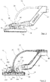
- the figures show a machine tool according to the invention, in particular its tool-side front portion, which is generally indicated by the reference numeral 10.
- the machine tool 10 is designed as a hand-held grinding machine, in particular as a long-necked sander, and comprises a tool unit (also called tool head) 12, a support structure 20 and a drive unit (not shown).
- the support structure 20 serves to hold the machine tool and connects the drive unit to the tool unit 12.
- the tool unit 12 is pivotally mounted at a distal end of the support structure 20 relative thereto.
- the tool unit 12 comprises in particular a hood device 14, which covers a tool holder 34b and a tool 36 received thereon of the tool unit 12.
- the hood device 14 is formed in the illustrated embodiment as a hood-shaped dust cover 14, which on a side facing the workpiece to be machined end comprises a sealing device which extends along a circumferential direction of the dust cover 14 and a sealing ring, in particular an annular brush ring 16 includes. This is how in the FIG. 3 represented relative to the dust cover 14 via a spring device 38 resiliently mounted, whereby a clean contact can be made to a surface to be machined.
- a hood space is formed, which serves to receive the resulting in the machining of a workpiece abrasion.
- the dust cover 14 also has suction openings 14a, in the region of which connecting sections 18 are provided, which mechanically and fluidically connect the dust cover 14 with a hinge connection 28.
- the support structure 20 of the present machine tool 10 comprises in the illustrated embodiment, a plurality of sections, namely a holding section or handle bar, a transition section 22 and a support fork or pivot fork 24, which has two support arms 26 for supporting the tool unit.
- a hinge connection 28 is provided between the connecting portions 18 of the dust cover 14 and the support arms 26 of the support fork 24, which due to their specific embodiment both a Pivoting the tool head 12 about two pivot axes A and B and a fluidic connection of the hood space with an air duct of the support structure 20 allows.
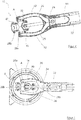
- the specific embodiment of the articulated connection 28 can be in particular also the FIGS. 3 to 5 remove.
- a joint body 28a Shown therein is a joint body 28a with a centrally tapered double cone, a thereto perpendicular, converging centrally with the double cone third cone and the third cone opposite fork structure, all of these elements are formed in the illustrated embodiment as interconnected with each other hollow body and together formed therein air duct 40.
- the joint body 28a is encompassed at free ends or its connection points in each case by annular joint parts 28b, wherein the joint body 28a is rotatably mounted with its connection points in each case within these annular genotype parts 28b.
- the joint body 28a as well as the joint parts 28b may be made of plastic, for example, which allows a particularly simple and cost-effective production of the joint.
- the joint parts 28b for rotatably receiving the joint body 28a may also be formed integrally with the connecting portions 18. However, a simpler production is made possible when the hinge parts 28b are formed separately, as shown in the figures.
- the joint body 28a allows by its interaction with the joint parts 28b in the manner of a universal joint pivoting of the tool unit 12 relative to the support structure 20 about the two axes of rotation A and B.
- the inner air duct 40 also the hood space within the hood-shaped dust cover 14 fluidly with the support structure 20 connected.
- the machine tool 10 further comprises a transmission shaft 32, which is at least partially guided within a tubular rod 30, which, like the transmission shaft 32, at least partially flexible. At its free end (distal end) 34a, the transmission shaft 32 drives the tool holder 34b, to which a tool 36 can be releasably attached.
- a machine tool in particular a long-necked sander, is provided, which takes less space in the region of its tool head than the known solutions do and is less susceptible to external damage.
- the functional combination of the support structure and the inclusion of a fluid channel for air guidance of the suction air a particularly simple and cost-effective solution is provided, the existing advantages of known solutions, without bringing their disadvantages with.
Landscapes
- Engineering & Computer Science (AREA)
- Mechanical Engineering (AREA)
- Grinding-Machine Dressing And Accessory Apparatuses (AREA)
- Finish Polishing, Edge Sharpening, And Grinding By Specific Grinding Devices (AREA)
- Auxiliary Devices For Machine Tools (AREA)
- Constituent Portions Of Griding Lathes, Driving, Sensing And Control (AREA)
Description
Die Erfindung betrifft eine Werkzeugmaschine gemäß Anspruch 1. Insbesondere betrifft die Erfindung eine Schleifmaschine, umfassend eine Antriebseinheit zum Antrieb eines verbindbaren Werkzeugs, eine Werkzeugeinheit die eine Werkzeugaufnahme aufweist, an der das verbindbare Werkzeug angebracht werden kann, sowie eine Staubschutzabdeckung im Bereich der Werkzeugaufnahme, wobei die Werkzeugeinheit mittels einer Tragstruktur an der Werkzeugmaschine angebracht ist. Die Werkzeugmaschine weist ferner zur Abführung von Absaugluft und darin enthaltenen Staubpartikeln von der Staubschutzabdeckung bis hin zur einer Absaugeinrichtung eine Luftführung auf.The invention relates to a machine tool according to claim 1. In particular, the invention relates to a grinding machine, comprising a drive unit for driving a connectable tool, a tool unit having a tool holder to which the connectable tool can be attached, and a dust cover in the tool holder, wherein the tool unit is attached to the machine tool by means of a support structure. The machine tool also has for the discharge of exhaust air and dust particles contained therein from the dust cover to a suction on an air duct.
Luftführungen innerhalb von Tragestrukturen von kleinen bzw. manuell betriebenen Werkzeugen sind hinlänglich bekannt, es sei beispielhaft auf die
Weiterhin ist eine Absaugvorrichtung vorgesehen, um den im Schleifbetrieb der Schleifmaschine anfallenden Abrieb aus dem Werkzeugkopf abführen zu können.Furthermore, a suction device is provided in order to be able to remove the abrasion occurring in the grinding operation of the grinding machine from the tool head.
Diese umfasst einen Absaugkanal, welcher den Haubenraum mit einer an einer Anschlussvorrichtung der Schleifmaschine anschließbaren Saugvorrichtung fluidwirksam verbindet. Im Bereich des Übergangs auf die Haubenvorrichtung ist ein flexibles Rohrelement angebracht, das das Haubengehäuse mit weiteren Abschnitten des Absaugkanals verbindet und zugleich eine gelenkige Verbindung des Werkzeugkopfes mit dem restlichen Maschinenkörper ermöglicht.This comprises a suction channel which fluidly connects the hood space with a suction device which can be connected to a connecting device of the grinding machine. In the area of the transition to the hood device, a flexible tube element is attached, which connects the hood housing with other sections of the suction channel and at the same time allows an articulated connection of the tool head with the rest of the machine body.
Demgegenüber besteht eine Aufgabe der vorliegenden Erfindung darin, die aus dem Stand der Technik bekannte Werkzeugmaschine weiter zu entwickeln und die aus der Praxis bekannt gewordenen Nachteile zumindest zu verringern.In contrast, an object of the present invention is to further develop the known from the prior art machine tool and at least to reduce the disadvantages known from practice.
Diese Aufgabe wird durch eine Werkzeugmaschine gemäß Anspruch 1 gelöst. Die wenigstens eine Gelenkverbindung weist einen Luftführungskanal auf, der sich durch die Gelenkverbindung hindurch erstreckt und in fluidischer Verbindung mit einer Absaugöffnung an der Staubschutzabdeckung steht. In jedem Fall zieht die wenigstens eine Gelenkverbindung zusätzlich Außenluft in den Luftführungskanal ein, wodurch ein quasi selbstreinigendes Gelenk geschaffen wird, da sich infolge der eingesogenen Außenluft keinerlei Schmutzpartikel innerhalb der Gelenkverbindung anzulagern vermögen.This object is achieved by a machine tool according to claim 1. The at least one articulated connection has an air guide channel which extends through the articulated connection and is in fluid communication with a suction opening on the dust protection cover. In any case, the at least one articulated connection additionally draws in outside air into the air duct, thereby creating a quasi-self-cleaning joint, since no dirt particles can accumulate within the articulated connection as a result of the absorbed external air.
Selbstverständlich wird dabei die zusätzliche in den Luftführungskanal eingezogene Außenluft in einem solchen Maß gehalten, dass der überwiegende Absaugeffekt eine Absaugung von Schmutzpartikeln im Bereich der Staubschutzabdeckung innerhalb des Haubenraums der haubenförmigen Abdeckung ermöglicht. Dies kann durch eine entsprechende Dimensionierung von Spalten an den relativ zueinander beweglichen Teilen der Gelenkverbindung oder durch zusätzliche, entsprechend dimensionierte Ausnehmungen erreicht werden.Of course, while the additional drawn into the air duct outer air is maintained to such an extent that the predominant suction effect allows extraction of dirt particles in the dust cover within the hood space of the hood-shaped cover. This can be achieved by a corresponding dimensioning of gaps on the relatively movable parts of the hinge connection or by additional, correspondingly dimensioned recesses.
Zudem kann vorgesehen sein, dass die wenigstens eine Gelenkverbindung aus Kunststoff hergestellt ist. Hierdurch wird eine besonders einfache und kostengünstig herzustellende Gelenkverbindung geschaffen.In addition, it can be provided that the at least one hinge connection is made of plastic. As a result, a particularly simple and inexpensive to produce articulated connection is created.
Die wenigstens eine Gelenkverbindung kann ferner zumindest einen Gelenkkörper sowie zumindest zwei, vorzugsweise vier Gelenkteile umfassen, die paarweise die wenigstens eine, vorzugsweise zwei Gelenkachsen definieren und durch ein Zusammenwirken mit dem Gelenkkörper eine drehbare Lagerung des Werkzeugeinheit an der Tragstruktur ermöglichen. Der Gelenkkörper kann bei dieser Ausgestaltung drehbar an den Gelenkteilen angebracht sein, insbesondere können die Gelenkteile einen Abschnitt des Gelenkkörpers drehbar aufnehmen oder abstützen.The at least one articulated connection can furthermore comprise at least one articulated body and at least two, preferably four articulated parts, which in pairs define the at least one, preferably two articulation axes and, by cooperation with the articulated body, enable rotatable mounting of the tool unit on the supporting structure. The joint body can be rotatably mounted on the joint parts in this embodiment, in particular, the joint parts rotatably receive or support a portion of the joint body.
Schließlich kann die Tragestruktur einen Anschlussstutzen zum Anschluss einer separat ausgebildeten Absaugeinrichtung insbesondere eines Allessaugers umfassen. Alternativ ist es jedoch selbstverständlich ebenfalls denkbar, dass die Werkzeugmaschine eine an dieser fest angebrachte Absaugeinrichtung umfasst.Finally, the support structure may comprise a connecting piece for connecting a separately formed suction device, in particular a Allessaugers. Alternatively, it is of course also conceivable that the machine tool comprises a permanently attached to this suction device.
Die Erfindung wird nachfolgend unter Bezugnahme auf die beigefügten Figuren detaillierter beschrieben, wobei diese eine bevorzugte Ausführungsform der Erfindung zeigen.The invention will be described in more detail below with reference to the attached figures, which show a preferred embodiment of the invention.
Weitere Merkmale der Erfindung ergeben sich zudem aus den beigefügten Ansprüchen.Further features of the invention will become apparent from the appended claims.
Die Figuren zeigen schematisch:
- Figur 1
- eine isometrische Ansicht eines vorderen Abschnitts der Werkzeugmaschine umfassend die Werkzeugeinheit sowie einen Teil der Tragestruktur der Werkzeugmaschine;
- Figur 2
- eine Seitenansicht der in
Figur 1 gezeigten Anordnung; - Figur 3
- eine geschnittene Darstellung der Anordnung gemäß den
Figuren 1 und2 in Seitenansicht; und - Figur 4
- eine Schnittansicht entlang der Schnittlinie IV-IV der
Figur 3 ; und - Figur 5
- eine Draufsicht auf die in den
Figuren 1 bis 4 gezeigten Anordnung.
- FIG. 1
- an isometric view of a front portion of the machine tool comprising the tool unit and a part of the support structure of the machine tool;
- FIG. 2
- a side view of in
FIG. 1 shown arrangement; - FIG. 3
- a sectional view of the arrangement according to the
FIGS. 1 and2 in side view; and - FIG. 4
- a sectional view taken along section line IV-IV of
FIG. 3 ; and - FIG. 5
- a plan view of the in the
FIGS. 1 to 4 shown arrangement.
Die Figuren zeigen eine erfindungsgemäße Werkzeugmaschine, insbesondere deren werkzeugseitigen vorderen Abschnitt, die allgemein mit dem Bezugszeichen 10 angegeben ist. Die Werkzeugmaschine 10 ist als handgehaltene Schleifmaschine, insbesondere als Langhalsschleifer, ausgebildet und umfasst eine Werkzeugeinheit (auch Werkzeugkopf genannt) 12, eine Tragestruktur 20 sowie eine Antriebseinheit (nicht dargestellt). Die Tragestruktur 20 dient zum Halten der Werkzeugmaschine und verbindet die Antriebseinheit mit der Werkzeugeinheit 12.The figures show a machine tool according to the invention, in particular its tool-side front portion, which is generally indicated by the
Die Werkzeugeinheit 12 ist an einem distalen Ende der Tragestruktur 20 relativ zu dieser schwenkbar angeordnet.The
Wie in der
Innerhalb der Staubschutzabdeckung 14 ist ein Haubenraum ausgebildet, der zur Aufnahme des bei der Bearbeitung eines Werkstücks anfallenden Abriebs dient.Within the
Die Staubschutzabdeckung 14 weist ferner Absaugöffnungen 14a auf, in deren Bereich Verbindungsabschnitte 18 vorgesehen sind, die die Staubschutzabdeckung 14 mechanisch und fluidisch mit einer Gelenkverbindung 28 verbinden.The
Die Tragestruktur 20 der vorliegenden Werkzeugmaschine 10 umfasst in der dargestellten Ausführungsform mehrere Abschnitte, nämlich einen nicht dargestellten Halteabschnitt bzw. Griffstab, einen Übergangsabschnitt 22 sowie eine Abstützgabel bzw. Schwenkgabel 24, die zur Abstützung der Werkzeugeinheit zwei Stützarme 26 aufweist.The
Wie in der
Darin gezeigt ist ein Gelenkkörper 28a mit einem sich mittig verjüngenden Doppelkegel, einem hierzu senkrechten, mittig mit dem Doppelkegel zusammenlaufenden dritten Kegel sowie einer dem dritten Kegel gegenüberliegenden Gabelstruktur, wobei alle diese Elemente in der dargestellten Ausführungsform als miteinander fluidisch verbundene Hohlkörper ausgebildet sind und gemeinsam einen darin ausgebildeten Luftführungskanal 40 bilden. Der Gelenkkörper 28a wird an freien Enden bzw. seinen Anschlussstellen jeweils von ringförmigen Gelenkteilen 28b umgriffen, wobei der Gelenkkörper 28a mit seinen Anschlussstellen jeweils drehbar innerhalb dieser ringförmigen Genkteile 28b gelagert ist.Shown therein is a
Der Gelenkkörper 28a wie auch die Gelenkteile 28b können beispielsweise aus Kunststoff hergestellt sein, was eine besonders einfache und kostengünstige Herstellung der Gelenkverbindung ermöglicht. Weiterhin können die Gelenkteile 28b zur drehbaren Aufnahme des Gelenkkörpers 28a auch einteilig mit den Verbindungsabschnitten 18 ausgebildet sein. Eine einfachere Herstellung wird jedoch ermöglich, wenn die Gelenkteile 28b separat ausgebildet sind, wie in den Figuren gezeigt.The
Der Gelenkkörper 28a ermöglicht durch sein Zusammenwirken mit den Gelenkteilen 28b in der Art eines Kreuzgelenks eine Verschwenkung der Werkzeugeinheit 12 relativ zu der Tragestruktur 20 um die beiden Drehachsen A und B. Durch den innenliegenden Luftführungskanal 40 wird zudem der Haubenraum innerhalb der haubenförmigen Staubschutzabdeckung 14 fluidisch mit der Tragestruktur 20 verbunden.The
Diese weist ebenfalls innerhalb ihrer Stützarme 26 kanalförmige Hohlräume 42 auf, die am Übergangsabschnitt 24 in einen gemeinsamen Kanal 44 münden, welcher mit einem Luftführungskanal der übrigen Tragestruktur fluidisch verbunden ist (nicht dargestellt).This also has within its
Die Werkzeugmaschine 10 umfasst ferner eine Übertragungswelle 32, die zumindest abschnittsweise innerhalb eines rohrförmigen Stabs 30 geführt ist, der, wie auch die Übertragungswelle 32, zumindest abschnittsweise flexibel ausgebildet sein kann. An ihrem freien Ende (distalen Ende) 34a treibt die Übertragungswelle 32 die Werkzeugaufnahme 34b an, an der ein Werkzeug 36 lösbar angebracht werden kann.The
Mit Hilfe der vorliegenden Verbindung wird eine Werkzeugmaschine, insbesondere ein Langhalsschleifer, bereitgestellt, der im Bereich seines Werkzeugkopfes weniger Bauraum in Anspruch nimmt als dies die bekannten Lösungen tun und gegenüber äußeren Beschädigungen zudem weniger anfällig ist. Durch die Funktionsvereinigung der Tragestruktur und der Aufnahme eines Fluidkanals für eine Luftführung der Absaugluft wird eine besonders einfache und kostengünstige Lösung bereitgestellt, die bestehende Vorteile von bekannten Lösungen aufgreift, ohne deren Nachteile mit zu bringen.With the aid of the present connection, a machine tool, in particular a long-necked sander, is provided, which takes less space in the region of its tool head than the known solutions do and is less susceptible to external damage. The functional combination of the support structure and the inclusion of a fluid channel for air guidance of the suction air, a particularly simple and cost-effective solution is provided, the existing advantages of known solutions, without bringing their disadvantages with.
Claims (7)
- Machine tool (10), in particular grinding machine:comprising a drive unit for driving a connectable tool (36),also comprising a tool unit (12) having a tool holder (34b), on which the connectable tool (36) can be fitted, and having a shroud-like dust-protection cover (14) in the region of the tool holder (34b), wherein the tool unit (12) is fitted on the machine tool (10) by means of a carrying structure (20),and further comprising an air guide (40, 42, 44, 46), which extends from the dust-protection cover (14) to a suction-extraction device for the purpose of channelling away suction-extraction air and dust particles contained therein, wherein the air guide (40, 42, 44, 46) is fully integrated in the carrying structure (20), and wherein the carrying structure (20) comprises at least one articulation connection (28), which connects the tool unit (12) to the machine tool (10) such that it can be rotated about at least one axis (A, B), preferably about two axes (A, B),characterized in that the at least one articulation connection (28) has appropriately dimensioned gaps on the articulation-connection parts which can be moved relative to one another, or has additional, appropriately dimensioned apertures, so that the at least one articulation connection (28) is able to draw additional outside air into the air-guide channel (40).
- Machine tool (10) according to Claim 1,
characterized in that the carrying structure (20) of the machine tool (10) comprises a handlebar, on which the drive unit and the tool unit (12) are fitted. - Machine tool (10) according to Claim 1 or 2,
characterized in that the carrying structure (20) comprises a supporting fork (24) with at least two supporting arms (26) for supporting the tool unit (12), wherein at least one of the supporting arms (26) comprises an integrally formed air-guide channel (42), which is in fluidic connection with a suction-extraction opening (14a) on the dust-protection cover (14). - Machine tool (10) according to one of the preceding claims,
characterized in that the one articulation connection (28) has an air-guide channel (40), which extends through the articulation connection (28) and is in fluidic connection with a suction-extraction opening (14a) on the dust-protection cover (14). - Machine tool (10) according to one of the preceding claims,
characterized in that the at least one articulation connection (28) is produced at least to some extent from plastics material. - Machine tool (10) according to one of the preceding claims,
characterized in that the at least one articulation connection (28) comprises at least one articulation body (28a) and at least two, preferably four, articulation parts (28b), which in pairs define the articulation axes (A, B). - Machine tool (10) according to one of the preceding claims,
characterized in that the carrying structure (20) comprises a connecting piece for the connection of a separately formed suction-extraction device, in particular of an all-purpose suction appliance.
Applications Claiming Priority (1)
| Application Number | Priority Date | Filing Date | Title |
|---|---|---|---|
| DE102014113881.3A DE102014113881A1 (en) | 2014-09-25 | 2014-09-25 | Machine tool and support structure for this |
Publications (3)
| Publication Number | Publication Date |
|---|---|
| EP3000559A2 EP3000559A2 (en) | 2016-03-30 |
| EP3000559A3 EP3000559A3 (en) | 2016-04-06 |
| EP3000559B1 true EP3000559B1 (en) | 2018-09-12 |
Family
ID=53886841
Family Applications (1)
| Application Number | Title | Priority Date | Filing Date |
|---|---|---|---|
| EP15177978.2A Active EP3000559B1 (en) | 2014-09-25 | 2015-07-23 | Machine tool and support structure therefor |
Country Status (2)
| Country | Link |
|---|---|
| EP (1) | EP3000559B1 (en) |
| DE (1) | DE102014113881A1 (en) |
Cited By (5)
| Publication number | Priority date | Publication date | Assignee | Title |
|---|---|---|---|---|
| US11867224B2 (en) | 2021-01-27 | 2024-01-09 | Black & Decker Inc. | Locking mechanism for two telescoping poles of a power tool |
| US11919127B2 (en) | 2019-10-23 | 2024-03-05 | Black & Decker Inc. | Pole sander |
| US11931851B2 (en) | 2019-10-23 | 2024-03-19 | Black & Decker Inc. | Pole sander |
| US11951585B2 (en) | 2019-10-23 | 2024-04-09 | Black & Decker Inc. | Pole sander |
| US12005547B2 (en) | 2019-10-23 | 2024-06-11 | Black & Decker Inc. | Pole sander |
Families Citing this family (3)
| Publication number | Priority date | Publication date | Assignee | Title |
|---|---|---|---|---|
| DE102016106556A1 (en) * | 2016-04-11 | 2017-10-12 | Festool Gmbh | Hand machine tool with a suction hose |
| EP3812093A1 (en) * | 2019-10-23 | 2021-04-28 | Black & Decker Inc. | Pole sander |
| CN111958434A (en) * | 2020-08-30 | 2020-11-20 | 陈维华 | A hand-held grinding device for machining |
Citations (1)
| Publication number | Priority date | Publication date | Assignee | Title |
|---|---|---|---|---|
| US20040180616A1 (en) * | 2003-03-11 | 2004-09-16 | Loveless Michael L. | Vacuum driven sander |
Family Cites Families (7)
| Publication number | Priority date | Publication date | Assignee | Title |
|---|---|---|---|---|
| US3826045A (en) * | 1973-09-14 | 1974-07-30 | Nat Detroit Inc | Abrading machine with dust collecting unit |
| US4759155A (en) * | 1987-03-06 | 1988-07-26 | Shaw Christopher J | Particle collecting sander |
| US5239783A (en) * | 1991-08-20 | 1993-08-31 | William Matechuk | Drywall sander |
| US7249996B1 (en) * | 2005-06-08 | 2007-07-31 | Mykhaylo Volyar | Vacuum sander |
| DE102008063508A1 (en) * | 2008-12-10 | 2010-06-17 | Flex-Elektrowerkzeuge Gmbh | Hand held cleaning / grinding machine |
| ES2369582B1 (en) * | 2009-10-01 | 2012-11-06 | Reinaldo García Berenguer | GRINDER FOR BODY REPAIR WITH ASPIRATION SYSTEM. |
| DE102012111990A1 (en) | 2012-12-07 | 2014-06-12 | Flex-Elektrowerkzeuge Gmbh | Hand held grinding machine |
-
2014
- 2014-09-25 DE DE102014113881.3A patent/DE102014113881A1/en not_active Ceased
-
2015
- 2015-07-23 EP EP15177978.2A patent/EP3000559B1/en active Active
Patent Citations (1)
| Publication number | Priority date | Publication date | Assignee | Title |
|---|---|---|---|---|
| US20040180616A1 (en) * | 2003-03-11 | 2004-09-16 | Loveless Michael L. | Vacuum driven sander |
Cited By (5)
| Publication number | Priority date | Publication date | Assignee | Title |
|---|---|---|---|---|
| US11919127B2 (en) | 2019-10-23 | 2024-03-05 | Black & Decker Inc. | Pole sander |
| US11931851B2 (en) | 2019-10-23 | 2024-03-19 | Black & Decker Inc. | Pole sander |
| US11951585B2 (en) | 2019-10-23 | 2024-04-09 | Black & Decker Inc. | Pole sander |
| US12005547B2 (en) | 2019-10-23 | 2024-06-11 | Black & Decker Inc. | Pole sander |
| US11867224B2 (en) | 2021-01-27 | 2024-01-09 | Black & Decker Inc. | Locking mechanism for two telescoping poles of a power tool |
Also Published As
| Publication number | Publication date |
|---|---|
| EP3000559A2 (en) | 2016-03-30 |
| DE102014113881A1 (en) | 2016-03-31 |
| EP3000559A3 (en) | 2016-04-06 |
Similar Documents
| Publication | Publication Date | Title |
|---|---|---|
| EP3000559B1 (en) | Machine tool and support structure therefor | |
| DE202014104588U1 (en) | Machine tool and support structure for this | |
| DE2813460C3 (en) | Rotating tool with suction housing | |
| EP3235602B1 (en) | Dust collecting apparatus having a supporting device | |
| DE102007042667A1 (en) | Polishing machine for lenses and method for polishing a lens with a processing machine | |
| EP2960003A1 (en) | Device for the removal of electrode caps on welding robots | |
| WO2017017286A2 (en) | Pneumatic cleaning gun | |
| EP3269504A1 (en) | Suction hood for machine tool | |
| EP2140931B9 (en) | Agitating machine with length-adjustable tool holder | |
| EP3235603A2 (en) | Dust collection device with a cover for a hand machine tool | |
| EP3224433B1 (en) | Underwater cleaning machine having a chassis system | |
| EP3431227B1 (en) | Hand-held machine tool connected to a suction device | |
| DE202005007213U1 (en) | Nozzle for vacuum cleaner | |
| DE4238245C3 (en) | Dust extraction device for a motor-driven device designed as a hand-held device | |
| DE1142681B (en) | Vacuum cleaner mouthpiece with two mutually movable tools | |
| DE102006056854A1 (en) | Hand tool with pivotally hinged vibration-insulated handle | |
| DE3333177A1 (en) | Cutting tool | |
| DE19821705A1 (en) | Suction device for sucking up dirt or the like | |
| DE102014200401B4 (en) | Grinding tool with a grinding element with internal drive | |
| DE102007006498A1 (en) | Automated machine finishing e.g. molding, device, for viscous material-crawler-type undercarriage preferably PVC-crawler-type undercarriage, has tool adjustable between operating and stowed positions, and control unit for automatic control | |
| DE202021100353U1 (en) | Angle head with adjustment of the positioning distance and positioning device for it | |
| EP3145647B1 (en) | Cleaning tool for a robot arm in order to clean threaded holes, stud bolts and surfaces, inter alia, on underbody structures | |
| DE202016104254U1 (en) | Accessory and its combination with a power tool | |
| EP2489443B1 (en) | Hose coupling device | |
| EP3269503A1 (en) | Suction hood with radial tool drawer opening |
Legal Events
| Date | Code | Title | Description |
|---|---|---|---|
| PUAL | Search report despatched |
Free format text: ORIGINAL CODE: 0009013 |
|
| PUAI | Public reference made under article 153(3) epc to a published international application that has entered the european phase |
Free format text: ORIGINAL CODE: 0009012 |
|
| AK | Designated contracting states |
Kind code of ref document: A2 Designated state(s): AL AT BE BG CH CY CZ DE DK EE ES FI FR GB GR HR HU IE IS IT LI LT LU LV MC MK MT NL NO PL PT RO RS SE SI SK SM TR |
|
| AX | Request for extension of the european patent |
Extension state: BA ME |
|
| AK | Designated contracting states |
Kind code of ref document: A3 Designated state(s): AL AT BE BG CH CY CZ DE DK EE ES FI FR GB GR HR HU IE IS IT LI LT LU LV MC MK MT NL NO PL PT RO RS SE SI SK SM TR |
|
| AX | Request for extension of the european patent |
Extension state: BA ME |
|
| RIC1 | Information provided on ipc code assigned before grant |
Ipc: B24B 55/10 20060101AFI20160301BHEP Ipc: B24B 7/00 20060101ALI20160301BHEP Ipc: B24B 7/18 20060101ALI20160301BHEP Ipc: B24B 23/02 20060101ALI20160301BHEP |
|
| 17P | Request for examination filed |
Effective date: 20160916 |
|
| RBV | Designated contracting states (corrected) |
Designated state(s): AL AT BE BG CH CY CZ DE DK EE ES FI FR GB GR HR HU IE IS IT LI LT LU LV MC MK MT NL NO PL PT RO RS SE SI SK SM TR |
|
| STAA | Information on the status of an ep patent application or granted ep patent |
Free format text: STATUS: EXAMINATION IS IN PROGRESS |
|
| 17Q | First examination report despatched |
Effective date: 20170328 |
|
| GRAP | Despatch of communication of intention to grant a patent |
Free format text: ORIGINAL CODE: EPIDOSNIGR1 |
|
| STAA | Information on the status of an ep patent application or granted ep patent |
Free format text: STATUS: GRANT OF PATENT IS INTENDED |
|
| INTG | Intention to grant announced |
Effective date: 20171215 |
|
| GRAJ | Information related to disapproval of communication of intention to grant by the applicant or resumption of examination proceedings by the epo deleted |
Free format text: ORIGINAL CODE: EPIDOSDIGR1 |
|
| STAA | Information on the status of an ep patent application or granted ep patent |
Free format text: STATUS: EXAMINATION IS IN PROGRESS |
|
| INTC | Intention to grant announced (deleted) | ||
| GRAP | Despatch of communication of intention to grant a patent |
Free format text: ORIGINAL CODE: EPIDOSNIGR1 |
|
| STAA | Information on the status of an ep patent application or granted ep patent |
Free format text: STATUS: GRANT OF PATENT IS INTENDED |
|
| INTG | Intention to grant announced |
Effective date: 20180417 |
|
| GRAS | Grant fee paid |
Free format text: ORIGINAL CODE: EPIDOSNIGR3 |
|
| GRAA | (expected) grant |
Free format text: ORIGINAL CODE: 0009210 |
|
| STAA | Information on the status of an ep patent application or granted ep patent |
Free format text: STATUS: THE PATENT HAS BEEN GRANTED |
|
| AK | Designated contracting states |
Kind code of ref document: B1 Designated state(s): AL AT BE BG CH CY CZ DE DK EE ES FI FR GB GR HR HU IE IS IT LI LT LU LV MC MK MT NL NO PL PT RO RS SE SI SK SM TR |
|
| REG | Reference to a national code |
Ref country code: GB Ref legal event code: FG4D Free format text: NOT ENGLISH |
|
| REG | Reference to a national code |
Ref country code: CH Ref legal event code: EP |
|
| REG | Reference to a national code |
Ref country code: IE Ref legal event code: FG4D Free format text: LANGUAGE OF EP DOCUMENT: GERMAN |
|
| REG | Reference to a national code |
Ref country code: DE Ref legal event code: R096 Ref document number: 502015005810 Country of ref document: DE |
|
| REG | Reference to a national code |
Ref country code: AT Ref legal event code: REF Ref document number: 1039983 Country of ref document: AT Kind code of ref document: T Effective date: 20181015 |
|
| REG | Reference to a national code |
Ref country code: NL Ref legal event code: MP Effective date: 20180912 |
|
| REG | Reference to a national code |
Ref country code: LT Ref legal event code: MG4D |
|
| PG25 | Lapsed in a contracting state [announced via postgrant information from national office to epo] |
Ref country code: FI Free format text: LAPSE BECAUSE OF FAILURE TO SUBMIT A TRANSLATION OF THE DESCRIPTION OR TO PAY THE FEE WITHIN THE PRESCRIBED TIME-LIMIT Effective date: 20180912 Ref country code: GR Free format text: LAPSE BECAUSE OF FAILURE TO SUBMIT A TRANSLATION OF THE DESCRIPTION OR TO PAY THE FEE WITHIN THE PRESCRIBED TIME-LIMIT Effective date: 20181213 Ref country code: RS Free format text: LAPSE BECAUSE OF FAILURE TO SUBMIT A TRANSLATION OF THE DESCRIPTION OR TO PAY THE FEE WITHIN THE PRESCRIBED TIME-LIMIT Effective date: 20180912 Ref country code: SE Free format text: LAPSE BECAUSE OF FAILURE TO SUBMIT A TRANSLATION OF THE DESCRIPTION OR TO PAY THE FEE WITHIN THE PRESCRIBED TIME-LIMIT Effective date: 20180912 Ref country code: NO Free format text: LAPSE BECAUSE OF FAILURE TO SUBMIT A TRANSLATION OF THE DESCRIPTION OR TO PAY THE FEE WITHIN THE PRESCRIBED TIME-LIMIT Effective date: 20181212 Ref country code: LT Free format text: LAPSE BECAUSE OF FAILURE TO SUBMIT A TRANSLATION OF THE DESCRIPTION OR TO PAY THE FEE WITHIN THE PRESCRIBED TIME-LIMIT Effective date: 20180912 Ref country code: BG Free format text: LAPSE BECAUSE OF FAILURE TO SUBMIT A TRANSLATION OF THE DESCRIPTION OR TO PAY THE FEE WITHIN THE PRESCRIBED TIME-LIMIT Effective date: 20181212 |
|
| PG25 | Lapsed in a contracting state [announced via postgrant information from national office to epo] |
Ref country code: AL Free format text: LAPSE BECAUSE OF FAILURE TO SUBMIT A TRANSLATION OF THE DESCRIPTION OR TO PAY THE FEE WITHIN THE PRESCRIBED TIME-LIMIT Effective date: 20180912 Ref country code: HR Free format text: LAPSE BECAUSE OF FAILURE TO SUBMIT A TRANSLATION OF THE DESCRIPTION OR TO PAY THE FEE WITHIN THE PRESCRIBED TIME-LIMIT Effective date: 20180912 Ref country code: LV Free format text: LAPSE BECAUSE OF FAILURE TO SUBMIT A TRANSLATION OF THE DESCRIPTION OR TO PAY THE FEE WITHIN THE PRESCRIBED TIME-LIMIT Effective date: 20180912 |
|
| PG25 | Lapsed in a contracting state [announced via postgrant information from national office to epo] |
Ref country code: IS Free format text: LAPSE BECAUSE OF FAILURE TO SUBMIT A TRANSLATION OF THE DESCRIPTION OR TO PAY THE FEE WITHIN THE PRESCRIBED TIME-LIMIT Effective date: 20190112 Ref country code: NL Free format text: LAPSE BECAUSE OF FAILURE TO SUBMIT A TRANSLATION OF THE DESCRIPTION OR TO PAY THE FEE WITHIN THE PRESCRIBED TIME-LIMIT Effective date: 20180912 Ref country code: PL Free format text: LAPSE BECAUSE OF FAILURE TO SUBMIT A TRANSLATION OF THE DESCRIPTION OR TO PAY THE FEE WITHIN THE PRESCRIBED TIME-LIMIT Effective date: 20180912 Ref country code: CZ Free format text: LAPSE BECAUSE OF FAILURE TO SUBMIT A TRANSLATION OF THE DESCRIPTION OR TO PAY THE FEE WITHIN THE PRESCRIBED TIME-LIMIT Effective date: 20180912 Ref country code: ES Free format text: LAPSE BECAUSE OF FAILURE TO SUBMIT A TRANSLATION OF THE DESCRIPTION OR TO PAY THE FEE WITHIN THE PRESCRIBED TIME-LIMIT Effective date: 20180912 Ref country code: IT Free format text: LAPSE BECAUSE OF FAILURE TO SUBMIT A TRANSLATION OF THE DESCRIPTION OR TO PAY THE FEE WITHIN THE PRESCRIBED TIME-LIMIT Effective date: 20180912 Ref country code: RO Free format text: LAPSE BECAUSE OF FAILURE TO SUBMIT A TRANSLATION OF THE DESCRIPTION OR TO PAY THE FEE WITHIN THE PRESCRIBED TIME-LIMIT Effective date: 20180912 Ref country code: EE Free format text: LAPSE BECAUSE OF FAILURE TO SUBMIT A TRANSLATION OF THE DESCRIPTION OR TO PAY THE FEE WITHIN THE PRESCRIBED TIME-LIMIT Effective date: 20180912 |
|
| PG25 | Lapsed in a contracting state [announced via postgrant information from national office to epo] |
Ref country code: SM Free format text: LAPSE BECAUSE OF FAILURE TO SUBMIT A TRANSLATION OF THE DESCRIPTION OR TO PAY THE FEE WITHIN THE PRESCRIBED TIME-LIMIT Effective date: 20180912 Ref country code: PT Free format text: LAPSE BECAUSE OF FAILURE TO SUBMIT A TRANSLATION OF THE DESCRIPTION OR TO PAY THE FEE WITHIN THE PRESCRIBED TIME-LIMIT Effective date: 20190112 Ref country code: SK Free format text: LAPSE BECAUSE OF FAILURE TO SUBMIT A TRANSLATION OF THE DESCRIPTION OR TO PAY THE FEE WITHIN THE PRESCRIBED TIME-LIMIT Effective date: 20180912 |
|
| REG | Reference to a national code |
Ref country code: DE Ref legal event code: R097 Ref document number: 502015005810 Country of ref document: DE |
|
| PLBE | No opposition filed within time limit |
Free format text: ORIGINAL CODE: 0009261 |
|
| STAA | Information on the status of an ep patent application or granted ep patent |
Free format text: STATUS: NO OPPOSITION FILED WITHIN TIME LIMIT |
|
| PG25 | Lapsed in a contracting state [announced via postgrant information from national office to epo] |
Ref country code: DK Free format text: LAPSE BECAUSE OF FAILURE TO SUBMIT A TRANSLATION OF THE DESCRIPTION OR TO PAY THE FEE WITHIN THE PRESCRIBED TIME-LIMIT Effective date: 20180912 |
|
| 26N | No opposition filed |
Effective date: 20190613 |
|
| PG25 | Lapsed in a contracting state [announced via postgrant information from national office to epo] |
Ref country code: SI Free format text: LAPSE BECAUSE OF FAILURE TO SUBMIT A TRANSLATION OF THE DESCRIPTION OR TO PAY THE FEE WITHIN THE PRESCRIBED TIME-LIMIT Effective date: 20180912 |
|
| PG25 | Lapsed in a contracting state [announced via postgrant information from national office to epo] |
Ref country code: MC Free format text: LAPSE BECAUSE OF FAILURE TO SUBMIT A TRANSLATION OF THE DESCRIPTION OR TO PAY THE FEE WITHIN THE PRESCRIBED TIME-LIMIT Effective date: 20180912 |
|
| REG | Reference to a national code |
Ref country code: CH Ref legal event code: PL |
|
| PG25 | Lapsed in a contracting state [announced via postgrant information from national office to epo] |
Ref country code: TR Free format text: LAPSE BECAUSE OF FAILURE TO SUBMIT A TRANSLATION OF THE DESCRIPTION OR TO PAY THE FEE WITHIN THE PRESCRIBED TIME-LIMIT Effective date: 20180912 |
|
| REG | Reference to a national code |
Ref country code: BE Ref legal event code: MM Effective date: 20190731 |
|
| PG25 | Lapsed in a contracting state [announced via postgrant information from national office to epo] |
Ref country code: BE Free format text: LAPSE BECAUSE OF NON-PAYMENT OF DUE FEES Effective date: 20190731 Ref country code: CH Free format text: LAPSE BECAUSE OF NON-PAYMENT OF DUE FEES Effective date: 20190731 Ref country code: LU Free format text: LAPSE BECAUSE OF NON-PAYMENT OF DUE FEES Effective date: 20190723 Ref country code: LI Free format text: LAPSE BECAUSE OF NON-PAYMENT OF DUE FEES Effective date: 20190731 |
|
| PG25 | Lapsed in a contracting state [announced via postgrant information from national office to epo] |
Ref country code: IE Free format text: LAPSE BECAUSE OF NON-PAYMENT OF DUE FEES Effective date: 20190723 |
|
| PG25 | Lapsed in a contracting state [announced via postgrant information from national office to epo] |
Ref country code: CY Free format text: LAPSE BECAUSE OF FAILURE TO SUBMIT A TRANSLATION OF THE DESCRIPTION OR TO PAY THE FEE WITHIN THE PRESCRIBED TIME-LIMIT Effective date: 20180912 |
|
| PG25 | Lapsed in a contracting state [announced via postgrant information from national office to epo] |
Ref country code: HU Free format text: LAPSE BECAUSE OF FAILURE TO SUBMIT A TRANSLATION OF THE DESCRIPTION OR TO PAY THE FEE WITHIN THE PRESCRIBED TIME-LIMIT; INVALID AB INITIO Effective date: 20150723 Ref country code: MT Free format text: LAPSE BECAUSE OF FAILURE TO SUBMIT A TRANSLATION OF THE DESCRIPTION OR TO PAY THE FEE WITHIN THE PRESCRIBED TIME-LIMIT Effective date: 20180912 |
|
| REG | Reference to a national code |
Ref country code: AT Ref legal event code: MM01 Ref document number: 1039983 Country of ref document: AT Kind code of ref document: T Effective date: 20200723 |
|
| PG25 | Lapsed in a contracting state [announced via postgrant information from national office to epo] |
Ref country code: AT Free format text: LAPSE BECAUSE OF NON-PAYMENT OF DUE FEES Effective date: 20200723 |
|
| PG25 | Lapsed in a contracting state [announced via postgrant information from national office to epo] |
Ref country code: MK Free format text: LAPSE BECAUSE OF FAILURE TO SUBMIT A TRANSLATION OF THE DESCRIPTION OR TO PAY THE FEE WITHIN THE PRESCRIBED TIME-LIMIT Effective date: 20180912 |
|
| P01 | Opt-out of the competence of the unified patent court (upc) registered |
Effective date: 20230513 |
|
| PGFP | Annual fee paid to national office [announced via postgrant information from national office to epo] |
Ref country code: DE Payment date: 20250722 Year of fee payment: 11 |
|
| PGFP | Annual fee paid to national office [announced via postgrant information from national office to epo] |
Ref country code: GB Payment date: 20250724 Year of fee payment: 11 |
|
| PGFP | Annual fee paid to national office [announced via postgrant information from national office to epo] |
Ref country code: FR Payment date: 20250723 Year of fee payment: 11 |