EP1769883A1 - Device for cleaning the shank and the contact surface of a machine tool - Google Patents
Device for cleaning the shank and the contact surface of a machine tool Download PDFInfo
- Publication number
- EP1769883A1 EP1769883A1 EP05021119A EP05021119A EP1769883A1 EP 1769883 A1 EP1769883 A1 EP 1769883A1 EP 05021119 A EP05021119 A EP 05021119A EP 05021119 A EP05021119 A EP 05021119A EP 1769883 A1 EP1769883 A1 EP 1769883A1
- Authority
- EP
- European Patent Office
- Prior art keywords
- stripping
- contact surface
- shaft
- tool
- cleaning
- Prior art date
- Legal status (The legal status is an assumption and is not a legal conclusion. Google has not performed a legal analysis and makes no representation as to the accuracy of the status listed.)
- Granted
Links
- 238000004140 cleaning Methods 0.000 title claims abstract description 15
- 238000011010 flushing procedure Methods 0.000 claims abstract description 8
- 229910000639 Spring steel Inorganic materials 0.000 claims description 2
- 239000002184 metal Substances 0.000 claims 2
- 238000007790 scraping Methods 0.000 abstract description 4
- 239000007788 liquid Substances 0.000 abstract description 2
- 230000000694 effects Effects 0.000 description 2
- 230000005540 biological transmission Effects 0.000 description 1
- 239000000356 contaminant Substances 0.000 description 1
- 230000001419 dependent effect Effects 0.000 description 1
- 238000011161 development Methods 0.000 description 1
- 230000018109 developmental process Effects 0.000 description 1
- 238000006073 displacement reaction Methods 0.000 description 1
- 239000012530 fluid Substances 0.000 description 1
- 238000000034 method Methods 0.000 description 1
Images


Classifications
-
- B—PERFORMING OPERATIONS; TRANSPORTING
- B23—MACHINE TOOLS; METAL-WORKING NOT OTHERWISE PROVIDED FOR
- B23Q—DETAILS, COMPONENTS, OR ACCESSORIES FOR MACHINE TOOLS, e.g. ARRANGEMENTS FOR COPYING OR CONTROLLING; MACHINE TOOLS IN GENERAL CHARACTERISED BY THE CONSTRUCTION OF PARTICULAR DETAILS OR COMPONENTS; COMBINATIONS OR ASSOCIATIONS OF METAL-WORKING MACHINES, NOT DIRECTED TO A PARTICULAR RESULT
- B23Q11/00—Accessories fitted to machine tools for keeping tools or parts of the machine in good working condition or for cooling work; Safety devices specially combined with or arranged in, or specially adapted for use in connection with, machine tools
- B23Q11/0042—Devices for removing chips
- B23Q11/005—Devices for removing chips by blowing
-
- B08B1/32—
Definitions
- the invention relates to a device according to the preamble of claim 1.
- Such devices are widely used in practice and for example from the EP 1 179 388 B1 known.
- the cleaning elements of these devices consist of brushes, by means of which, in the case of a corresponding rotary drive of the brushes, the shaft or the contact surface are cleaned.
- This embodiment has the disadvantage that the brush wear on the one hand and on the other hand pollute itself. After a certain period of operation, they therefore no longer clean reliably.
- the invention is therefore the object of developing a device of the generic type so that a perfect cleaning of shaft and contact surface of a machine tool is permanently guaranteed.
- the device shown in the drawing for cleaning the shaft and the contact surface of a machine tool has a housing 1, which may be attached to a machine tool or a transport device for transporting tools from a magazine to a tool spindle of a machine tool, as for example in US Pat of the EP 1 179 388 B1 is shown and described.
- a tool clamping device 2 is arranged, which has a tension rod 3.
- This clamping rod 3 has on her one - in Fig. 1 lower end - not shown jaws, which engage in a cavity of a HSK shaft 4 of a tool 5, wherein "HSK" has the meaning of "hollow shaft cone".
- the tension rod 3 is loaded with a biased against the housing 1 biased screw-pressure spring 6, the displacements of the tension rod 3 by this spring 6, So away from the tool 5, which spreads in the cavity of the shaft 4 located clamping jaws and thus the tool 5 pulls into the housing 1 and holds.
- the shaft 4 is radially fixed by the clamping device 2.
- the clamping rod 3 is loosened in the opposite direction by means of a piston 7 attached to the end of the clamping rod 3 opposite the tool 5, which can be acted upon by a pressure medium connection 8 with pressure medium, as a rule with pressure fluid, so that a release the tension rod 3 is against the force of the spring 6.
- Such tool clamping devices 2 are common in tool spindles and are also used in devices for cleaning tool shanks, as shown in EP 1 179 388 B1 evident.
- a scraper sleeve 9 is rotatably mounted, which is rotatably driven by means of a mounted on the housing 1 gear motor 10.
- the drive transmission takes place by means of a toothed pinion 11 attached to the motor 10, which engages in a toothed ring 12 mounted on the stripper sleeve 9.
- stripping sleeve 9 On the stripping sleeve 9 are distributed over the inner circumference distributed a plurality of shank stripping plates 13 for stripping the surface of the HSK shaft 4. Furthermore, a plurality of contact surface stripping plates 14 are attached to the stripping sleeve 9, which serve for stripping, that is, cleaning the contact surface 14 of the tool 5.
- This contact surface 15 extends radially to the central longitudinal axis 16 of the tool 5 and serves to rest against a corresponding alignment counter-surface on the tool clamping device of the tool spindle of a machine tool.
- the HSK shaft 4 is received in a corresponding cone of the tool clamping device of the tool spindle.
- the shank stripping plates 13, 14 are made of spring steel.
- the shank stripping plates 13 are fastened by means of screws 17 to the inner wall 18 of the stripping sleeve 9. They extend in the direction of the axis 16 over the area which is to be cleaned on the shaft 4. They have at their two in the direction of the axis 16 extending, in the circumferential direction of the inner wall 18 of the sleeve 9 spaced edges stripping edges 19, 20 which rest elastically resiliently against the cone-shaped shaft 4, so when turning the stripping sleeve. 9 by means of the motor 10 about the axis 16, both the leading and the trailing scraper edge 19 and 20 chips, dirt and the like from the shaft 4 strip.
- the contact surface stripping plates 14 are fastened by means of screws 22. They have an elastically resilient abutting on the contact surface 15 stripping edge 23, the cleaning effect is naturally best when it - relative to the direction of rotation 24 of the stripping sleeve 9 - is arranged leading.
- Both the wiper edges 19, 20, and the wiper edge 23 extend obliquely from the shaft stripping plate 13 or from the contact surface stripping plate 14 away from the shaft 4 and the contact surface 15, so that their cleaning or stripping effect always best, if they - are arranged leading in relation to the direction of rotation 24.
- the shaft 4 is secured against twisting during cleaning by the fact that projections 25 formed on the tensioning rod 3 engage in corresponding recesses 26 on the shaft 4.
- a flushing medium connection 27 is furthermore formed, which is connected to one or more flushing channels 28 in the stripping sleeve 9, so that flushing medium, that is, flushing gas or flushing liquid, during the stripping - Or cleaning process for cleaning and in particular for the removal of the stripped contaminants can be directed to the shaft 4.
Abstract
Description
Die Erfindung betrifft eine Vorrichtung nach dem Oberbegriff des Anspruches 1.The invention relates to a device according to the preamble of
Derartige Vorrichtungen sind in der Praxis allgemein verbreitet und beispielsweise aus der
Der Erfindung liegt daher die Aufgabe zugrunde, eine Vorrichtung der gattungsgemäßen Art so weiterzubilden, dass eine einwandfreie Reinigung von Schaft und Anlagefläche eines Maschinen-Werkzeugs dauerhaft gewährleistet ist.The invention is therefore the object of developing a device of the generic type so that a perfect cleaning of shaft and contact surface of a machine tool is permanently guaranteed.
Diese Aufgabe wird erfindungsgemäß durch das Merkmal im Kennzeichnungsteil des Anspruches 1 gelöst. Der mittels der Abstreif-Kante abgestreifte Schmutz beziehungsweise die abgestreiften Späne haften jedenfalls nicht an der Abstreif-Kante an. Die Abstreif-Kanten selber werden durch die Relativbewegung zwischen Schaft beziehungsweise Anlagefläche einerseits und Abstreif-Kante andererseits selbsttätig nachgeschärft und behalten dadurch ihre Funktionsfähigkeit.This object is achieved by the feature in the characterizing part of
Die Unteransprüche enthalten vorteilhafte Weiterbildungen der Erfindung.The dependent claims contain advantageous developments of the invention.
Weitere Merkmale, Einzelheiten und Vorteile der Erfindung ergeben sich im Übrigen aus der nachfolgenden Beschreibung eines Ausführungsbeispiels anhand der Zeichnung. Es zeigt
- Fig. 1 einen Längs-Mittel-Schnitt durch eine Vorrichtung nach der Erfindung,
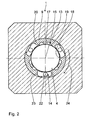
- Fig. 2 einen Querschnitt durch die Vorrichtung nach Fig. 1,
- Fig. 3 eine Teil-Vergrößerung aus Fig. 1, die ein Schaft-Abstreif-Blech zeigt, und
- Fig. 4 eine Teil-Vergrößerung aus Fig. 1, die ein Anlageflächen-Abstreif Blech zeigt.
- 1 shows a longitudinal center section through a device according to the invention,
- 2 shows a cross section through the device according to Fig. 1,
- Fig. 3 is a partial enlargement of Fig. 1, showing a shaft-stripping plate, and
- Fig. 4 is a partial enlargement of Fig. 1, showing a contact surface stripping plate.
Die in der Zeichnung dargestellte Vorrichtung zum Reinigen des Schaftes und der Anlagefläche eines Maschinen-Werkzeuges weist ein Gehäuse 1 auf, das an einer Werkzeugmaschine oder einer Transporteinrichtung zum Transport von Werkzeugen von einem Magazin zu einer Werkzeugspindel einer Werkzeugmaschine angebracht sein kann, wie es beispielsweise in der
Im Gehäuse 1 ist eine Abstreif-Hülse 9 drehbar gelagert, die mittels eines am Gehäuse 1 angebrachten Getriebe-Motors 10 drehantreibbar ist. Die Antriebsübertragung erfolgt mittels eines am Motor 10 angebrachten Zahn-Ritzels 11, das in einen auf der Abstreif-Hülse 9 angebrachten Zahn-Ring 12 eingreift.In the
An der Abstreif-Hülse 9 sind über deren Innen-Umfang verteilt mehrere Schaft-Abstreif-Bleche 13 zum Abstreifen der Oberfläche des HSK-Schaftes 4 angebracht. Des Weiteren sind an der Abstreif-Hülse 9 mehrere Anlageflächen-Abstreif-Bleche 14 angebracht, die zum Abstreifen, das heißt Reinigen der Anlagefläche 14 des Werkzeugs 5 dienen. Diese Anlagefläche 15 erstreckt sich radial zur Mittel-Längs-Achse 16 des Werkzeugs 5 und dient zur Anlage an einer entsprechenden Ausricht-Gegen-Fläche an der Werkzeug-Spanneinrichtung der Werkzeugspindel einer Werkzeugmaschine. Der HSK-Schaft 4 wird dagegen in einem entsprechenden Konus der Werkzeug-Spanneinrichtung der Werkzeugspindel aufgenommen.On the
Die Schaft-Abstreif-Bleche 13, 14 bestehen aus Federstahl. Die Schaft-Abstreif-Bleche 13 sind mittels Schrauben 17 an der Innenwand 18 der Abstreif-Hülse 9 befestigt. Sie erstrecken sich in Richtung der Achse 16 über den Bereich, der am Schaft 4 zu reinigen ist. Sie weisen an ihren beiden sich in Richtung der Achse 16 erstreckenden, in Umfangsrichtung der Innenwand 18 der Hülse 9 voneinander beabstandeten Rändern Abstreif-Kanten 19, 20 auf, die elastisch federnd gegen den konusförmigen Schaft 4 anliegen, sodass beim Drehen der Abstreif-Hülse 9 mittels des Motors 10 um die Achse 16 sowohl die voreilende als auch die nacheilende Abstreif-Kante 19 bzw. 20 Späne, Schmutz und dergleichen vom Schaft 4 abstreifen.The
An der zugeordneten Stirnseite 21 der Abstreif-Hülse 9 sind die Anlageflächen-Abstreif-Bleche 14 mittels Schrauben 22 befestigt. Sie weisen eine elastisch federnd an der Anlagefläche 15 anliegende Abstreif-Kante 23 auf, deren Reinigungswirkung naturgemäß am besten ist, wenn sie - bezogen auf die Drehrichtung 24 der Abstreif-Hülse 9 - voreilend angeordnet ist. Sowohl die Abstreif-Kanten 19, 20, als auch die Abstreif-Kante 23 verlaufen vom Schaft-Abstreif-Blech 13 beziehungsweise vom Anlagenflächen-Abstreif-Blech 14 weg schräg nach vom zum Schaft 4 beziehungsweise zur Anlagefläche 15, sodass ihre Reinigungs- beziehungsweise AbstreifWirkung immer am besten ist, wenn sie - bezogen auf die Drehrichtung 24 - voreilend angeordnet sind. Der Schaft 4 wird gegen ein Verdrehen während der Reinigung dadurch gesichert, dass an der Spannstange 3 ausgebildete Vorsprünge 25 in entsprechende Ausnehmungen 26 an dem Schaft 4 eingreifen.At the associated
Im Gehäuse 1 ist weiterhin ein Spül-Medium-Anschluss 27 ausgebildet, der mit ein oder mehreren Spül-Kanälen 28 in der Abstreif-Hülse 9 verbunden ist, sodass Spül-Medium, das heißt Spül-Gas oder Spül-Flüssigkeit, während des Abstreif- beziehungsweise Reinigungs-Vorgangs zum Reinigen und insbesondere zum Abtransport der abgestreiften Verunreinigungen auf den Schaft 4 gerichtet werden kann.In the
Claims (6)
dass die Reinigungs-Elemente als Abstreif-Bleche (13, 14) ausgebildet sind, die jeweils mindestens eine an den Schaft (4) beziehungsweise die Anlagefläche (15) elastisch federnd anlegbare Abstreif-Kante (19, 20, 23) aufweisen.Device for cleaning a shaft (4) and a contact surface (15) of a machine tool (5),
in that the cleaning elements are in the form of stripper plates (13, 14) which each have at least one stripping edge (19, 20, 23) which can be elastically resiliently applied to the shaft (4) or the contact surface (15).
dass die Abstreif-Bleche (13, 14) aus Federstahl bestehen.Device according to claim 1, characterized in that
that the stripping metal sheets (13, 14) made of spring steel.
dass die Abstreif-Bleche (13, 14) einstückig ausgebildet sind.Device according to Claim 1 or 2, characterized
that the stripping plates (13, 14) are integrally formed.
dass die Abstreif-Bleche (13, 14) lös- und auswechselbar am Träger angebracht sind.Device according to one of claims 1 to 3, characterized
that the stripping metal sheets (13, 14) detachably and replaceably mounted on the carrier.
dass der Träger als den Schaft (4) zumindest im Wesentlichen aufnehmende Abstreif-Hülse (9) ausgebildet ist, an deren Innenwand (18) das mindestens eine Schaft-Abstreif-Blech (13) und an deren Stirnseite (21) das mindestens eine Anlageflächen-Abstreif-Blech (14) angebracht ist.Device according to one of claims 1 to 4, characterized
in that the support is constructed as a stripping sleeve (9) at least substantially receiving the shank (4), on the inner wall (18) of which the at least one shank stripping plate (13) and on its end face (21) the at least one contact surface Stripping plate (14) is attached.
dass mindestens ein in den Träger mündender Spül-Kanal (26) für ein Spül-Medium vorgesehen ist.Device according to one of claims 1 to 5, characterized
in that at least one flushing channel (26) opening into the support is provided for a flushing medium.
Priority Applications (3)
| Application Number | Priority Date | Filing Date | Title |
|---|---|---|---|
| EP05021119A EP1769883B1 (en) | 2005-09-28 | 2005-09-28 | Device for cleaning the shank and the contact surface of a machine tool |
| AT05021119T ATE380092T1 (en) | 2005-09-28 | 2005-09-28 | DEVICE FOR CLEANING THE SHANK AND THE CONTACT SURFACE OF A MACHINE TOOL |
| DE502005002178T DE502005002178D1 (en) | 2005-09-28 | 2005-09-28 | Device for cleaning the shaft and the contact surface of a machine tool |
Applications Claiming Priority (1)
| Application Number | Priority Date | Filing Date | Title |
|---|---|---|---|
| EP05021119A EP1769883B1 (en) | 2005-09-28 | 2005-09-28 | Device for cleaning the shank and the contact surface of a machine tool |
Publications (2)
| Publication Number | Publication Date |
|---|---|
| EP1769883A1 true EP1769883A1 (en) | 2007-04-04 |
| EP1769883B1 EP1769883B1 (en) | 2007-12-05 |
Family
ID=35351670
Family Applications (1)
| Application Number | Title | Priority Date | Filing Date |
|---|---|---|---|
| EP05021119A Active EP1769883B1 (en) | 2005-09-28 | 2005-09-28 | Device for cleaning the shank and the contact surface of a machine tool |
Country Status (3)
| Country | Link |
|---|---|
| EP (1) | EP1769883B1 (en) |
| AT (1) | ATE380092T1 (en) |
| DE (1) | DE502005002178D1 (en) |
Cited By (3)
| Publication number | Priority date | Publication date | Assignee | Title |
|---|---|---|---|---|
| DE102007000726A1 (en) | 2007-09-12 | 2009-04-02 | Miksch Gmbh | Tool cone cleaning device for tool fitting, has vibrating element with data transfer device which has basket-shaped design such that vibrating element partially encompasses lateral surface of tool cone |
| CN102527652A (en) * | 2011-12-31 | 2012-07-04 | 太原重工股份有限公司 | Cleaning device for oil and dust of machine with rotation relation between upper part and lower part thereof |
| DE102019127362A1 (en) * | 2019-10-10 | 2021-04-15 | Narr Beteiligungs Gmbh | Jig |
Citations (3)
| Publication number | Priority date | Publication date | Assignee | Title |
|---|---|---|---|---|
| CH615105A5 (en) * | 1977-10-17 | 1980-01-15 | Dixi Sa | Apparatus for cleaning the spindle taper holes of machine tools and use thereof |
| EP0945213A2 (en) * | 1998-03-24 | 1999-09-29 | DECKEL MAHO GmbH | Cleaning apparatus for conical shanks of tool holders |
| EP1179388A2 (en) * | 2000-08-08 | 2002-02-13 | Gebr. Heller Maschinenfabrik GmbH | Method of cleaning tool shafts and device for carying out such a method |
-
2005
- 2005-09-28 EP EP05021119A patent/EP1769883B1/en active Active
- 2005-09-28 AT AT05021119T patent/ATE380092T1/en active
- 2005-09-28 DE DE502005002178T patent/DE502005002178D1/en active Active
Patent Citations (3)
| Publication number | Priority date | Publication date | Assignee | Title |
|---|---|---|---|---|
| CH615105A5 (en) * | 1977-10-17 | 1980-01-15 | Dixi Sa | Apparatus for cleaning the spindle taper holes of machine tools and use thereof |
| EP0945213A2 (en) * | 1998-03-24 | 1999-09-29 | DECKEL MAHO GmbH | Cleaning apparatus for conical shanks of tool holders |
| EP1179388A2 (en) * | 2000-08-08 | 2002-02-13 | Gebr. Heller Maschinenfabrik GmbH | Method of cleaning tool shafts and device for carying out such a method |
Cited By (4)
| Publication number | Priority date | Publication date | Assignee | Title |
|---|---|---|---|---|
| DE102007000726A1 (en) | 2007-09-12 | 2009-04-02 | Miksch Gmbh | Tool cone cleaning device for tool fitting, has vibrating element with data transfer device which has basket-shaped design such that vibrating element partially encompasses lateral surface of tool cone |
| DE102007000726B4 (en) * | 2007-09-12 | 2009-12-03 | Miksch Gmbh | Device for cleaning a tool cone of a tool holder |
| CN102527652A (en) * | 2011-12-31 | 2012-07-04 | 太原重工股份有限公司 | Cleaning device for oil and dust of machine with rotation relation between upper part and lower part thereof |
| DE102019127362A1 (en) * | 2019-10-10 | 2021-04-15 | Narr Beteiligungs Gmbh | Jig |
Also Published As
| Publication number | Publication date |
|---|---|
| DE502005002178D1 (en) | 2008-01-17 |
| ATE380092T1 (en) | 2007-12-15 |
| EP1769883B1 (en) | 2007-12-05 |
Similar Documents
| Publication | Publication Date | Title |
|---|---|---|
| EP0065293B1 (en) | Cleaning apparatus for a machine spindle | |
| EP0385133B1 (en) | Device for removing damaged spots from rubber parts | |
| DE102013210158A1 (en) | Roll-shaped wire brush | |
| EP3000559B1 (en) | Machine tool and support structure therefor | |
| DE202014104588U1 (en) | Machine tool and support structure for this | |
| DE202011000400U1 (en) | toolholder | |
| DE10251983A1 (en) | Doctor blade mounting, to clean roller surfaces in the papermaking and steel industries, has a mounting tube at the base plate to fit into a quadrilateral tube attached to the cover plate | |
| EP1769883B1 (en) | Device for cleaning the shank and the contact surface of a machine tool | |
| DE4037944C2 (en) | Hand tool for thread processing | |
| DE4400969A1 (en) | Device on hand-held machine tools for turning tools | |
| CH649011A5 (en) | Pipe cleaning device in particular for internally coated pipes | |
| DE19913747C2 (en) | Device for cleaning or cleaning elongated cavities | |
| DE102008054925A1 (en) | Drilling tool for rock | |
| DE19818284A1 (en) | Wall core cutting tool | |
| WO2019086212A1 (en) | Drilling tool | |
| EP1331290B1 (en) | Device for reversibly connecting a rotating tool to a spindle | |
| EP0172157B1 (en) | Holding element for the working units of a cylindrical brush | |
| DE19639748B4 (en) | Device for cleaning joints | |
| DE102005057368A1 (en) | Clutch for receiving of tool e.g. drilling or cutting tool, has damping element arranged between connecting part and tool housing for transmission of torque | |
| DE2540942C3 (en) | Honing device | |
| DE202006006225U1 (en) | Intermittent removal device for material residue on rotating brush heads has additional perforated disk on brush head connecting to axial-displacement setting unit | |
| EP1559525B1 (en) | Rotatable tool | |
| DE10121986B4 (en) | Multi-blade reamer with internal coolant supply | |
| EP1122013B1 (en) | Core bit | |
| DE10011246A1 (en) | Device for external cleaning of pipes has semi-circular base component located perpendicularly to axis of pipe, and exchangeable scraper element installed on base component and encompassing half the pipe |
Legal Events
| Date | Code | Title | Description |
|---|---|---|---|
| PUAI | Public reference made under article 153(3) epc to a published international application that has entered the european phase |
Free format text: ORIGINAL CODE: 0009012 |
|
| AK | Designated contracting states |
Kind code of ref document: A1 Designated state(s): AT BE BG CH CY CZ DE DK EE ES FI FR GB GR HU IE IS IT LI LT LU LV MC NL PL PT RO SE SI SK TR |
|
| AX | Request for extension of the european patent |
Extension state: AL BA HR MK YU |
|
| GRAP | Despatch of communication of intention to grant a patent |
Free format text: ORIGINAL CODE: EPIDOSNIGR1 |
|
| 17P | Request for examination filed |
Effective date: 20070413 |
|
| GRAS | Grant fee paid |
Free format text: ORIGINAL CODE: EPIDOSNIGR3 |
|
| GRAA | (expected) grant |
Free format text: ORIGINAL CODE: 0009210 |
|
| AK | Designated contracting states |
Kind code of ref document: B1 Designated state(s): AT BE BG CH CY CZ DE DK EE ES FI FR GB GR HU IE IS IT LI LT LU LV MC NL PL PT RO SE SI SK TR |
|
| REG | Reference to a national code |
Ref country code: GB Ref legal event code: FG4D Free format text: NOT ENGLISH |
|
| AKX | Designation fees paid |
Designated state(s): AT BE BG CH CY CZ DE DK EE ES FI FR GB GR HU IE IS IT LI LT LU LV MC NL PL PT RO SE SI SK TR |
|
| REG | Reference to a national code |
Ref country code: IE Ref legal event code: FG4D Free format text: LANGUAGE OF EP DOCUMENT: GERMAN |
|
| GBT | Gb: translation of ep patent filed (gb section 77(6)(a)/1977) |
Effective date: 20071205 |
|
| REG | Reference to a national code |
Ref country code: CH Ref legal event code: EP |
|
| REF | Corresponds to: |
Ref document number: 502005002178 Country of ref document: DE Date of ref document: 20080117 Kind code of ref document: P |
|
| PG25 | Lapsed in a contracting state [announced via postgrant information from national office to epo] |
Ref country code: SE Free format text: LAPSE BECAUSE OF FAILURE TO SUBMIT A TRANSLATION OF THE DESCRIPTION OR TO PAY THE FEE WITHIN THE PRESCRIBED TIME-LIMIT Effective date: 20080305 Ref country code: NL Free format text: LAPSE BECAUSE OF FAILURE TO SUBMIT A TRANSLATION OF THE DESCRIPTION OR TO PAY THE FEE WITHIN THE PRESCRIBED TIME-LIMIT Effective date: 20071205 Ref country code: ES Free format text: LAPSE BECAUSE OF FAILURE TO SUBMIT A TRANSLATION OF THE DESCRIPTION OR TO PAY THE FEE WITHIN THE PRESCRIBED TIME-LIMIT Effective date: 20080316 |
|
| ET | Fr: translation filed | ||
| PG25 | Lapsed in a contracting state [announced via postgrant information from national office to epo] |
Ref country code: SI Free format text: LAPSE BECAUSE OF FAILURE TO SUBMIT A TRANSLATION OF THE DESCRIPTION OR TO PAY THE FEE WITHIN THE PRESCRIBED TIME-LIMIT Effective date: 20071205 Ref country code: FI Free format text: LAPSE BECAUSE OF FAILURE TO SUBMIT A TRANSLATION OF THE DESCRIPTION OR TO PAY THE FEE WITHIN THE PRESCRIBED TIME-LIMIT Effective date: 20071205 Ref country code: LV Free format text: LAPSE BECAUSE OF FAILURE TO SUBMIT A TRANSLATION OF THE DESCRIPTION OR TO PAY THE FEE WITHIN THE PRESCRIBED TIME-LIMIT Effective date: 20071205 Ref country code: LT Free format text: LAPSE BECAUSE OF FAILURE TO SUBMIT A TRANSLATION OF THE DESCRIPTION OR TO PAY THE FEE WITHIN THE PRESCRIBED TIME-LIMIT Effective date: 20071205 Ref country code: PL Free format text: LAPSE BECAUSE OF FAILURE TO SUBMIT A TRANSLATION OF THE DESCRIPTION OR TO PAY THE FEE WITHIN THE PRESCRIBED TIME-LIMIT Effective date: 20071205 |
|
| NLV1 | Nl: lapsed or annulled due to failure to fulfill the requirements of art. 29p and 29m of the patents act | ||
| PG25 | Lapsed in a contracting state [announced via postgrant information from national office to epo] |
Ref country code: CZ Free format text: LAPSE BECAUSE OF FAILURE TO SUBMIT A TRANSLATION OF THE DESCRIPTION OR TO PAY THE FEE WITHIN THE PRESCRIBED TIME-LIMIT Effective date: 20071205 Ref country code: IS Free format text: LAPSE BECAUSE OF FAILURE TO SUBMIT A TRANSLATION OF THE DESCRIPTION OR TO PAY THE FEE WITHIN THE PRESCRIBED TIME-LIMIT Effective date: 20080405 |
|
| PG25 | Lapsed in a contracting state [announced via postgrant information from national office to epo] |
Ref country code: RO Free format text: LAPSE BECAUSE OF FAILURE TO SUBMIT A TRANSLATION OF THE DESCRIPTION OR TO PAY THE FEE WITHIN THE PRESCRIBED TIME-LIMIT Effective date: 20071205 Ref country code: SK Free format text: LAPSE BECAUSE OF FAILURE TO SUBMIT A TRANSLATION OF THE DESCRIPTION OR TO PAY THE FEE WITHIN THE PRESCRIBED TIME-LIMIT Effective date: 20071205 |
|
| PG25 | Lapsed in a contracting state [announced via postgrant information from national office to epo] |
Ref country code: PT Free format text: LAPSE BECAUSE OF FAILURE TO SUBMIT A TRANSLATION OF THE DESCRIPTION OR TO PAY THE FEE WITHIN THE PRESCRIBED TIME-LIMIT Effective date: 20080505 |
|
| REG | Reference to a national code |
Ref country code: IE Ref legal event code: FD4D |
|
| PLBE | No opposition filed within time limit |
Free format text: ORIGINAL CODE: 0009261 |
|
| STAA | Information on the status of an ep patent application or granted ep patent |
Free format text: STATUS: NO OPPOSITION FILED WITHIN TIME LIMIT |
|
| PG25 | Lapsed in a contracting state [announced via postgrant information from national office to epo] |
Ref country code: IE Free format text: LAPSE BECAUSE OF FAILURE TO SUBMIT A TRANSLATION OF THE DESCRIPTION OR TO PAY THE FEE WITHIN THE PRESCRIBED TIME-LIMIT Effective date: 20071205 Ref country code: DK Free format text: LAPSE BECAUSE OF FAILURE TO SUBMIT A TRANSLATION OF THE DESCRIPTION OR TO PAY THE FEE WITHIN THE PRESCRIBED TIME-LIMIT Effective date: 20071205 |
|
| 26N | No opposition filed |
Effective date: 20080908 |
|
| PG25 | Lapsed in a contracting state [announced via postgrant information from national office to epo] |
Ref country code: GR Free format text: LAPSE BECAUSE OF FAILURE TO SUBMIT A TRANSLATION OF THE DESCRIPTION OR TO PAY THE FEE WITHIN THE PRESCRIBED TIME-LIMIT Effective date: 20080306 |
|
| BERE | Be: lapsed |
Owner name: HULLER HILLE G.M.B.H. Effective date: 20080930 |
|
| PG25 | Lapsed in a contracting state [announced via postgrant information from national office to epo] |
Ref country code: MC Free format text: LAPSE BECAUSE OF NON-PAYMENT OF DUE FEES Effective date: 20080930 Ref country code: EE Free format text: LAPSE BECAUSE OF FAILURE TO SUBMIT A TRANSLATION OF THE DESCRIPTION OR TO PAY THE FEE WITHIN THE PRESCRIBED TIME-LIMIT Effective date: 20071205 |
|
| PG25 | Lapsed in a contracting state [announced via postgrant information from national office to epo] |
Ref country code: BE Free format text: LAPSE BECAUSE OF NON-PAYMENT OF DUE FEES Effective date: 20080930 Ref country code: CY Free format text: LAPSE BECAUSE OF FAILURE TO SUBMIT A TRANSLATION OF THE DESCRIPTION OR TO PAY THE FEE WITHIN THE PRESCRIBED TIME-LIMIT Effective date: 20071205 |
|
| PG25 | Lapsed in a contracting state [announced via postgrant information from national office to epo] |
Ref country code: HU Free format text: LAPSE BECAUSE OF FAILURE TO SUBMIT A TRANSLATION OF THE DESCRIPTION OR TO PAY THE FEE WITHIN THE PRESCRIBED TIME-LIMIT Effective date: 20080606 Ref country code: LU Free format text: LAPSE BECAUSE OF NON-PAYMENT OF DUE FEES Effective date: 20080928 |
|
| PG25 | Lapsed in a contracting state [announced via postgrant information from national office to epo] |
Ref country code: TR Free format text: LAPSE BECAUSE OF FAILURE TO SUBMIT A TRANSLATION OF THE DESCRIPTION OR TO PAY THE FEE WITHIN THE PRESCRIBED TIME-LIMIT Effective date: 20071205 |
|
| PG25 | Lapsed in a contracting state [announced via postgrant information from national office to epo] |
Ref country code: BG Free format text: LAPSE BECAUSE OF FAILURE TO SUBMIT A TRANSLATION OF THE DESCRIPTION OR TO PAY THE FEE WITHIN THE PRESCRIBED TIME-LIMIT Effective date: 20071205 |
|
| PGFP | Annual fee paid to national office [announced via postgrant information from national office to epo] |
Ref country code: AT Payment date: 20110915 Year of fee payment: 7 |
|
| REG | Reference to a national code |
Ref country code: AT Ref legal event code: MM01 Ref document number: 380092 Country of ref document: AT Kind code of ref document: T Effective date: 20120928 |
|
| PG25 | Lapsed in a contracting state [announced via postgrant information from national office to epo] |
Ref country code: AT Free format text: LAPSE BECAUSE OF NON-PAYMENT OF DUE FEES Effective date: 20120928 |
|
| REG | Reference to a national code |
Ref country code: FR Ref legal event code: PLFP Year of fee payment: 12 |
|
| REG | Reference to a national code |
Ref country code: FR Ref legal event code: PLFP Year of fee payment: 13 |
|
| REG | Reference to a national code |
Ref country code: FR Ref legal event code: PLFP Year of fee payment: 14 |
|
| P01 | Opt-out of the competence of the unified patent court (upc) registered |
Effective date: 20230522 |
|
| PGFP | Annual fee paid to national office [announced via postgrant information from national office to epo] |
Ref country code: GB Payment date: 20230921 Year of fee payment: 19 |
|
| PGFP | Annual fee paid to national office [announced via postgrant information from national office to epo] |
Ref country code: FR Payment date: 20230918 Year of fee payment: 19 Ref country code: DE Payment date: 20230919 Year of fee payment: 19 |
|
| PGFP | Annual fee paid to national office [announced via postgrant information from national office to epo] |
Ref country code: IT Payment date: 20230929 Year of fee payment: 19 Ref country code: CH Payment date: 20231001 Year of fee payment: 19 |