EP2638258B1 - Abgasnachbearbeitungsvorrichtung und -verfahren für ein fahrzeug mit einer durch ein peltier-element erwärmten reduktionsmittelverdampfungsoberfläche - Google Patents
Abgasnachbearbeitungsvorrichtung und -verfahren für ein fahrzeug mit einer durch ein peltier-element erwärmten reduktionsmittelverdampfungsoberfläche Download PDFInfo
- Publication number
- EP2638258B1 EP2638258B1 EP11840488.8A EP11840488A EP2638258B1 EP 2638258 B1 EP2638258 B1 EP 2638258B1 EP 11840488 A EP11840488 A EP 11840488A EP 2638258 B1 EP2638258 B1 EP 2638258B1
- Authority
- EP
- European Patent Office
- Prior art keywords
- peltier element
- exhaust
- exhaust pipe
- reducing agent
- treatment device
- Prior art date
- Legal status (The legal status is an assumption and is not a legal conclusion. Google has not performed a legal analysis and makes no representation as to the accuracy of the status listed.)
- Active
Links
- 239000003638 chemical reducing agent Substances 0.000 title claims description 73
- 238000000034 method Methods 0.000 title claims description 19
- 239000007789 gas Substances 0.000 claims description 64
- 239000007788 liquid Substances 0.000 claims description 54
- MWUXSHHQAYIFBG-UHFFFAOYSA-N nitrogen oxide Inorganic materials O=[N] MWUXSHHQAYIFBG-UHFFFAOYSA-N 0.000 claims description 36
- 238000010521 absorption reaction Methods 0.000 claims description 22
- XSQUKJJJFZCRTK-UHFFFAOYSA-N Urea Chemical compound NC(N)=O XSQUKJJJFZCRTK-UHFFFAOYSA-N 0.000 claims description 13
- 239000004202 carbamide Substances 0.000 claims description 12
- 239000003054 catalyst Substances 0.000 claims description 12
- 238000010792 warming Methods 0.000 claims description 12
- 230000015572 biosynthetic process Effects 0.000 claims description 7
- 238000011144 upstream manufacturing Methods 0.000 claims description 7
- 239000004020 conductor Substances 0.000 claims description 3
- 229910052751 metal Inorganic materials 0.000 claims description 3
- 239000002184 metal Substances 0.000 claims description 3
- 150000002739 metals Chemical class 0.000 claims description 3
- QGZKDVFQNNGYKY-UHFFFAOYSA-N Ammonia Chemical compound N QGZKDVFQNNGYKY-UHFFFAOYSA-N 0.000 description 16
- 239000000243 solution Substances 0.000 description 6
- 229910021529 ammonia Inorganic materials 0.000 description 4
- 229910000069 nitrogen hydride Inorganic materials 0.000 description 4
- 239000000654 additive Substances 0.000 description 3
- 230000000996 additive effect Effects 0.000 description 3
- 238000006243 chemical reaction Methods 0.000 description 3
- 238000001149 thermolysis Methods 0.000 description 3
- 238000009834 vaporization Methods 0.000 description 3
- 238000001321 HNCO Methods 0.000 description 2
- OWIKHYCFFJSOEH-UHFFFAOYSA-N Isocyanic acid Chemical compound N=C=O OWIKHYCFFJSOEH-UHFFFAOYSA-N 0.000 description 2
- 238000004140 cleaning Methods 0.000 description 2
- 238000010586 diagram Methods 0.000 description 2
- 230000000694 effects Effects 0.000 description 2
- 230000007062 hydrolysis Effects 0.000 description 2
- 238000006460 hydrolysis reaction Methods 0.000 description 2
- RYGMFSIKBFXOCR-UHFFFAOYSA-N Copper Chemical compound [Cu] RYGMFSIKBFXOCR-UHFFFAOYSA-N 0.000 description 1
- 238000001816 cooling Methods 0.000 description 1
- 229910052802 copper Inorganic materials 0.000 description 1
- 239000010949 copper Substances 0.000 description 1
- 239000008367 deionised water Substances 0.000 description 1
- 239000002283 diesel fuel Substances 0.000 description 1
- 239000012153 distilled water Substances 0.000 description 1
- 230000005611 electricity Effects 0.000 description 1
- 238000002309 gasification Methods 0.000 description 1
- 238000002347 injection Methods 0.000 description 1
- 239000007924 injection Substances 0.000 description 1
- 238000002844 melting Methods 0.000 description 1
- 230000008018 melting Effects 0.000 description 1
- 230000000737 periodic effect Effects 0.000 description 1
- 239000007787 solid Substances 0.000 description 1
- 230000001360 synchronised effect Effects 0.000 description 1
- 230000005676 thermoelectric effect Effects 0.000 description 1
- XLYOFNOQVPJJNP-UHFFFAOYSA-N water Substances O XLYOFNOQVPJJNP-UHFFFAOYSA-N 0.000 description 1
Images


Classifications
-
- F—MECHANICAL ENGINEERING; LIGHTING; HEATING; WEAPONS; BLASTING
- F01—MACHINES OR ENGINES IN GENERAL; ENGINE PLANTS IN GENERAL; STEAM ENGINES
- F01N—GAS-FLOW SILENCERS OR EXHAUST APPARATUS FOR MACHINES OR ENGINES IN GENERAL; GAS-FLOW SILENCERS OR EXHAUST APPARATUS FOR INTERNAL COMBUSTION ENGINES
- F01N3/00—Exhaust or silencing apparatus having means for purifying, rendering innocuous, or otherwise treating exhaust
- F01N3/08—Exhaust or silencing apparatus having means for purifying, rendering innocuous, or otherwise treating exhaust for rendering innocuous
- F01N3/10—Exhaust or silencing apparatus having means for purifying, rendering innocuous, or otherwise treating exhaust for rendering innocuous by thermal or catalytic conversion of noxious components of exhaust
- F01N3/18—Exhaust or silencing apparatus having means for purifying, rendering innocuous, or otherwise treating exhaust for rendering innocuous by thermal or catalytic conversion of noxious components of exhaust characterised by methods of operation; Control
- F01N3/20—Exhaust or silencing apparatus having means for purifying, rendering innocuous, or otherwise treating exhaust for rendering innocuous by thermal or catalytic conversion of noxious components of exhaust characterised by methods of operation; Control specially adapted for catalytic conversion ; Methods of operation or control of catalytic converters
- F01N3/206—Adding periodically or continuously substances to exhaust gases for promoting purification, e.g. catalytic material in liquid form, NOx reducing agents
-
- F—MECHANICAL ENGINEERING; LIGHTING; HEATING; WEAPONS; BLASTING
- F01—MACHINES OR ENGINES IN GENERAL; ENGINE PLANTS IN GENERAL; STEAM ENGINES
- F01N—GAS-FLOW SILENCERS OR EXHAUST APPARATUS FOR MACHINES OR ENGINES IN GENERAL; GAS-FLOW SILENCERS OR EXHAUST APPARATUS FOR INTERNAL COMBUSTION ENGINES
- F01N3/00—Exhaust or silencing apparatus having means for purifying, rendering innocuous, or otherwise treating exhaust
- F01N3/08—Exhaust or silencing apparatus having means for purifying, rendering innocuous, or otherwise treating exhaust for rendering innocuous
- F01N3/10—Exhaust or silencing apparatus having means for purifying, rendering innocuous, or otherwise treating exhaust for rendering innocuous by thermal or catalytic conversion of noxious components of exhaust
- F01N3/18—Exhaust or silencing apparatus having means for purifying, rendering innocuous, or otherwise treating exhaust for rendering innocuous by thermal or catalytic conversion of noxious components of exhaust characterised by methods of operation; Control
- F01N3/20—Exhaust or silencing apparatus having means for purifying, rendering innocuous, or otherwise treating exhaust for rendering innocuous by thermal or catalytic conversion of noxious components of exhaust characterised by methods of operation; Control specially adapted for catalytic conversion ; Methods of operation or control of catalytic converters
- F01N3/2066—Selective catalytic reduction [SCR]
-
- F—MECHANICAL ENGINEERING; LIGHTING; HEATING; WEAPONS; BLASTING
- F01—MACHINES OR ENGINES IN GENERAL; ENGINE PLANTS IN GENERAL; STEAM ENGINES
- F01N—GAS-FLOW SILENCERS OR EXHAUST APPARATUS FOR MACHINES OR ENGINES IN GENERAL; GAS-FLOW SILENCERS OR EXHAUST APPARATUS FOR INTERNAL COMBUSTION ENGINES
- F01N13/00—Exhaust or silencing apparatus characterised by constructional features ; Exhaust or silencing apparatus, or parts thereof, having pertinent characteristics not provided for in, or of interest apart from, groups F01N1/00 - F01N5/00, F01N9/00, F01N11/00
- F01N13/08—Other arrangements or adaptations of exhaust conduits
-
- F—MECHANICAL ENGINEERING; LIGHTING; HEATING; WEAPONS; BLASTING
- F01—MACHINES OR ENGINES IN GENERAL; ENGINE PLANTS IN GENERAL; STEAM ENGINES
- F01N—GAS-FLOW SILENCERS OR EXHAUST APPARATUS FOR MACHINES OR ENGINES IN GENERAL; GAS-FLOW SILENCERS OR EXHAUST APPARATUS FOR INTERNAL COMBUSTION ENGINES
- F01N9/00—Electrical control of exhaust gas treating apparatus
-
- F—MECHANICAL ENGINEERING; LIGHTING; HEATING; WEAPONS; BLASTING
- F01—MACHINES OR ENGINES IN GENERAL; ENGINE PLANTS IN GENERAL; STEAM ENGINES
- F01N—GAS-FLOW SILENCERS OR EXHAUST APPARATUS FOR MACHINES OR ENGINES IN GENERAL; GAS-FLOW SILENCERS OR EXHAUST APPARATUS FOR INTERNAL COMBUSTION ENGINES
- F01N2240/00—Combination or association of two or more different exhaust treating devices, or of at least one such device with an auxiliary device, not covered by indexing codes F01N2230/00 or F01N2250/00, one of the devices being
- F01N2240/02—Combination or association of two or more different exhaust treating devices, or of at least one such device with an auxiliary device, not covered by indexing codes F01N2230/00 or F01N2250/00, one of the devices being a heat exchanger
-
- F—MECHANICAL ENGINEERING; LIGHTING; HEATING; WEAPONS; BLASTING
- F01—MACHINES OR ENGINES IN GENERAL; ENGINE PLANTS IN GENERAL; STEAM ENGINES
- F01N—GAS-FLOW SILENCERS OR EXHAUST APPARATUS FOR MACHINES OR ENGINES IN GENERAL; GAS-FLOW SILENCERS OR EXHAUST APPARATUS FOR INTERNAL COMBUSTION ENGINES
- F01N2240/00—Combination or association of two or more different exhaust treating devices, or of at least one such device with an auxiliary device, not covered by indexing codes F01N2230/00 or F01N2250/00, one of the devices being
- F01N2240/16—Combination or association of two or more different exhaust treating devices, or of at least one such device with an auxiliary device, not covered by indexing codes F01N2230/00 or F01N2250/00, one of the devices being an electric heater, i.e. a resistance heater
-
- F—MECHANICAL ENGINEERING; LIGHTING; HEATING; WEAPONS; BLASTING
- F01—MACHINES OR ENGINES IN GENERAL; ENGINE PLANTS IN GENERAL; STEAM ENGINES
- F01N—GAS-FLOW SILENCERS OR EXHAUST APPARATUS FOR MACHINES OR ENGINES IN GENERAL; GAS-FLOW SILENCERS OR EXHAUST APPARATUS FOR INTERNAL COMBUSTION ENGINES
- F01N2610/00—Adding substances to exhaust gases
- F01N2610/02—Adding substances to exhaust gases the substance being ammonia or urea
-
- F—MECHANICAL ENGINEERING; LIGHTING; HEATING; WEAPONS; BLASTING
- F01—MACHINES OR ENGINES IN GENERAL; ENGINE PLANTS IN GENERAL; STEAM ENGINES
- F01N—GAS-FLOW SILENCERS OR EXHAUST APPARATUS FOR MACHINES OR ENGINES IN GENERAL; GAS-FLOW SILENCERS OR EXHAUST APPARATUS FOR INTERNAL COMBUSTION ENGINES
- F01N2610/00—Adding substances to exhaust gases
- F01N2610/10—Adding substances to exhaust gases the substance being heated, e.g. by heating tank or supply line of the added substance
- F01N2610/102—Adding substances to exhaust gases the substance being heated, e.g. by heating tank or supply line of the added substance after addition to exhaust gases, e.g. by a passively or actively heated surface in the exhaust conduit
-
- Y—GENERAL TAGGING OF NEW TECHNOLOGICAL DEVELOPMENTS; GENERAL TAGGING OF CROSS-SECTIONAL TECHNOLOGIES SPANNING OVER SEVERAL SECTIONS OF THE IPC; TECHNICAL SUBJECTS COVERED BY FORMER USPC CROSS-REFERENCE ART COLLECTIONS [XRACs] AND DIGESTS
- Y02—TECHNOLOGIES OR APPLICATIONS FOR MITIGATION OR ADAPTATION AGAINST CLIMATE CHANGE
- Y02A—TECHNOLOGIES FOR ADAPTATION TO CLIMATE CHANGE
- Y02A50/00—TECHNOLOGIES FOR ADAPTATION TO CLIMATE CHANGE in human health protection, e.g. against extreme weather
- Y02A50/20—Air quality improvement or preservation, e.g. vehicle emission control or emission reduction by using catalytic converters
-
- Y—GENERAL TAGGING OF NEW TECHNOLOGICAL DEVELOPMENTS; GENERAL TAGGING OF CROSS-SECTIONAL TECHNOLOGIES SPANNING OVER SEVERAL SECTIONS OF THE IPC; TECHNICAL SUBJECTS COVERED BY FORMER USPC CROSS-REFERENCE ART COLLECTIONS [XRACs] AND DIGESTS
- Y02—TECHNOLOGIES OR APPLICATIONS FOR MITIGATION OR ADAPTATION AGAINST CLIMATE CHANGE
- Y02T—CLIMATE CHANGE MITIGATION TECHNOLOGIES RELATED TO TRANSPORTATION
- Y02T10/00—Road transport of goods or passengers
- Y02T10/10—Internal combustion engine [ICE] based vehicles
- Y02T10/12—Improving ICE efficiencies
Definitions
- the invention relates to an exhaust post-treatment device for a vehicle according to the preamble of claim 1 and a method for post-treatment of exhaust gases from vehicles according to the preamble of claim 13.
- the SCR method i.e. a method for selective reduction of nitrogen oxides, is used to clean the vehicle's exhaust gases so that those released into the surroundings do not contain high contents of nitrogen oxides.
- a liquid urea solution injected into the exhaust pipe may be used as NO x reducing agent.
- liquid urea solution may entail problems at low exhaust temperatures in that the reducing agent injected does not become vaporised quickly enough, with consequent formation in the exhaust system of deposits which may lead to pressure drop, a problem which is solved by maintaining such a high exhaust temperature that the reducing agent injected becomes vaporised in the exhaust pipe.
- EP 2 078 834 A refers to a method and a system for cleaning of exhaust gases at such a high exhaust temperature that an additive becomes gasified such that the exhaust gases are warmed to shorten the time required before injection of liquid additive can commence, which involves using a great deal of energy.
- US 2005/0204733 A1 refers to a device in which a thermoelectric element is used to generate electrical energy.
- US 2009107119 refers to a system for cleaning exhaust gases including a heater.
- gaseous ammonia injected into the exhaust pipe may also be used as reducing agent.
- gaseous reducing agent reduces problems due to deposits of reducing agent in the exhaust pipe, since they only occur if the exhaust temperature before the exhaust gases reach the catalyst falls so low that the reducing agent is converted from gas to liquid or solid.
- DE 10 2007 058 768 A1 refers to a device and a method for post-treatment of exhaust gases whereby gaseous reducing agent, e.g. ammonia, is injected into the exhaust pipe, and energy present in the exhaust gases is used to vaporise the reducing agent before it is injected in the exhaust pipe.
- gaseous reducing agent e.g. ammonia
- the object of the present invention is to propose an exhaust post-treatment device for a vehicle and a method for post-treatment of exhaust gases from vehicles, which device can operate even if the temperature of the exhaust gases is low.
- an exhaust post-treatment device according to the characterising part of claim 1 and a method for post-treatment of exhaust gases from vehicles according to the characterising part of claim 13.
- an exhaust post-treatment device for a vehicle which is adapted to reducing nitrogen oxides present in the vehicle's exhaust gases by supplying liquid reducing agent to the exhaust gases in an exhaust pipe according to the characterising part of claim 1 presents the characteristic that the device comprises a Peltier element and is adapted to locally warming a surface within the exhaust pipe by means of a Peltier element by using thermal energy from the exhaust gases to vaporise liquid reducing agent which reaches the surface
- a method for post-treatment of exhaust gases from vehicles by supplying liquid reducing agent to the exhaust gases in an exhaust pipe in order to reduce nitrogen oxides present in them presents the characteristic of locally warming a surface within the exhaust pipe with an exhaust post-treatment device comprising a Peltier element by using thermal energy from the exhaust gases to vaporise liquid reducing agent which
- one side of the Peltier element is adapted to diverting thermal energy from the exhaust gases to the Peltier element by said energy being absorbed on one side of the Peltier element, and the other side of the Peltier element is adapted to locally warming a surface within the exhaust pipe by thermal energy being delivered from the Peltier element to the surface within the exhaust pipe, thereby achieving the advantage that the exhaust post-treatment device needs only moderate amounts of energy for its operation.
- the Peltier element comprises at least two electrodes made of different semiconductive metals such that every second electrode is of N type and the alternate electrodes are of P type, which electrodes are arranged to extend from one side of the Peltier element to the other side of the Peltier element and are connected in series via conductors to a direct-current source, such that closing the electric circuit causes electrons in the N type electrode to move in the opposite direction to the current, and holes in the P type electrode to move in the direction of the current, both of them diverting heat from one side of the Peltier element to the other side of the Peltier element, thereby achieving the advantage that the configuration of the exhaust post-treatment device is adaptable, e.g. depending on the desired effect of the Peltier element.
- the thermal energy absorption side of the Peltier element may be situated at least partly within the exhaust pipe or adjacent to the outside of the exhaust pipe, the thermal energy absorption side of the Peltier element may be situated downstream or upstream of the supply device for supply of liquid reducing agent to the exhaust gases in the exhaust pipe, as seen in their direction of flow, the thermal energy delivery side of the Peltier element may be situated adjacent to the outside of the exhaust pipe or at least partly within the exhaust pipe, the surface which is locally warmed within the exhaust pipe may be a surface of the thermal energy delivery side of the Peltier element which is situated within the exhaust pipe, or a surface on the inside of the exhaust pipe, a catalyst may be provided in the exhaust pipe downstream of the supply device for the liquid reducing agent, as seen in the direction of flow of the exhaust gases, and a control unit may be provided to control the Peltier element and the supply of liquid reducing agent, thereby achieving the advantage that the configuration of the exhaust post-treatment device is adaptable, e.g. depending on whether high efficiency or simple configuration and easy
- the thermal energy absorption side of the Peltier element may be warmed by the exhaust gases, direct current may be applied across the Peltier element, and thermal energy may be delivered to the surface within the exhaust pipe from the thermal energy delivery side of the Peltier element, thereby achieving the advantage that the exhaust post-treatment device needs only moderate amounts of energy for its operation.
- Fig. 1 depicts schematically an exhaust post-treatment device 2 for a vehicle 4 according to a first embodiment of the invention, which device 2 comprises a Peltier element 6 also called a thermoelectric cooling element.
- the Peltier element 6 itself comprises at least one "thermocouple" composed of two electrodes 8, 10 made of different semiconductive metals such that every second electrode 8 is of N type and the alternate electrodes 10 are of P type, which electrodes 8, 10 are arranged to extend from one side 28 of the Peltier element 6 to the other side 30 of the Peltier element 6 and are connected in series via conductors 12, preferably made of copper, to a direct-current source 14, such that closing the electric circuit causes electrons in the N type electrode to move in an opposite direction to the current, and holes in the P type electrode to move in the direction of the current, as illustrated in the diagram, both of them diverting heat from one side 28 of the Peltier element 6 to the other side 30 of the Peltier element 6.
- thermoelectric effects in the Peltier element 6 which result in thermal energy being absorbed on one side 28 of the Peltier element 6 and being delivered on the other side 30 of the Peltier element 6, i.e. the Peltier element 6 has a heat absorption side 28 and a heat delivery side 30.
- the exhaust post-treatment device 2 comprises also a supply device 16 for supply to the exhaust gases 20 of liquid reducing agent 18 which is intended for reduction of nitrogen oxides present in the exhaust gases 20.
- the Peltier element 6 is thus adapted to diverting thermal energy from the exhaust gases 20 and to thereby locally warming a surface 31 which according to this embodiment is part of the inside wall of an exhaust pipe 32 by diverting thermal energy from the Peltier element 6 to the surface 31 within the exhaust pipe 32.
- the exhaust post-treatment device 2 is adapted to reducing nitrogen oxides present in the exhaust gases 20 of the vehicle 4 by supplying liquid reducing agent 18 to the exhaust gases 20 in an exhaust pipe 32, and to locally warming a surface 31 within the exhaust pipe 32 by means of a Peltier element 6 by using thermal energy from the exhaust gases 20 to vaporise liquid reducing agent 18 which reaches the surface 31, and thereby prevent formation of deposits of reducing agent within the exhaust pipe.
- Using a heat pump as above makes it possible to increase the temperature locally on the surface 31 within the exhaust pipe 32 where liquid reducing agent 18 is supplied, e.g. by being injected, so that vaporisation of the reducing agent 18 can take place.
- the liquid reducing agent 18 is an NO x reducing agent, e.g. a liquid NO x reducing agent such as a liquid urea solution, e.g. the additive marketed under the trade name "Ad Blue" which contains 32.5 wt% of urea in distilled/deionised water.
- a liquid NO x reducing agent such as a liquid urea solution
- Ad Blue the additive marketed under the trade name "Ad Blue” which contains 32.5 wt% of urea in distilled/deionised water.
- the surface 31 in the exhaust pipe 32 needs to be kept at a temperature of at least about 200°C for vaporisation to be assured.
- At least one control unit 34 is preferably provided to control the Peltier element 6 and the supply of liquid reducing agent 18, depending on which reducing agent is used and on the temperature of the exhaust gases in the exhaust pipe 32, so that these activities only take place when necessary. If the Peltier element 6 and the supply of liquid reducing agent 18 are controlled by separate control units, the latter have to be synchronised such that the control unit for controlling the Peltier element 6 preferably serves as a "slave unit" to the control unit for controlling the supply of liquid reducing agent 18. If the exhaust gases 20 are very cold, e.g.
- the control unit 34 will block the supply of liquid reducing agent 18 in the exhaust pipe 32.
- the control unit 34 will block operation of the Peltier element 6.
- the control unit 34 will ensure that reducing agent 18 is supplied to the exhaust gases 20 and that the Peltier element 6 is in operation if the exhaust temperature is so high that the reducing agent 18 which does not reach the surface 31 within the exhaust pipe 32 can become gasified, but not so high that the reducing agent 18 which reaches, and thereby cools, a surface 31 within the exhaust pipe 32 also becomes gasified.
- This temperature range may be set by the control unit 34, depending on which reducing agent is used.
- the exhaust temperature has to be high enough for the reducing agent 18 which does not reach a surface 31 within the exhaust pipe 32 to become gasified, which temperature is different for different reducing agents 18.
- the exhaust temperature required for liquid NO x reducing agent which reaches and thereby cools a surface 31 within the exhaust pipe 32 to nevertheless become gasified depends on various factors such as the temperature of the liquid reducing agent at the time of supply, the dimensions of the exhaust pipe, the velocity of the exhaust flow, the size of the area reached by liquid reducing agent, etc.
- the exhaust gases may normally be at a temperature of between about 200°C and about 700°C during operation.
- the heat absorption side 28 of the Peltier element 6 is situated within an exhaust pipe 32, so warm exhaust gases 20 pass a surface 36 of the heat absorption side 28 of the Peltier element 6, leading to warming of the heat absorption side 28 of the Peltier element 6.
- the exhaust post-treatment device 2 works according to the following principle during operation of the Peltier element 6, based on the example of using a liquid urea solution as reducing agent.
- the heat delivery side 30 of the Peltier element 6 is situated adjacent to the wall of the exhaust pipe 32 where there is risk of deposits, i.e. preferably adjacent to the region where the liquid reducing agent 18 from the supply device 16 reaches the inside surface of the exhaust pipe, e.g. centrally to the supply device 16 for liquid reducing agent, where the heat delivery side 30 of the Peltier element 6 delivers thermal energy to a surface 31 within the exhaust pipe 32, in this case to the wall of the exhaust pipe, and thereby locally warms the inside surface of the exhaust pipe as a result of the heat delivery side 30 of the Peltier element 6 being in thermal contact with the exhaust pipe 32.
- the aforesaid method makes it possible for the thermal energy present in the exhaust gases to be utilised, despite the exhaust temperature being only moderate, e.g. about 100-300°C, to substantially completely gasify the reducing agent 18. Without the local warming described above of a surface 31 within the exhaust pipe 32, moderate exhaust temperatures might cause parts of the reducing agent reaching this surface 31 to solidify, potentially causing deposits and consequent pressure drop in the exhaust system. Increasing pressure drop may preferably be used to detect build-up of deposits. Such deposits certainly burn away if the exhaust temperature thereafter becomes very high, but on long runs at low load and steady speed, e.g. when driving an unladen vehicle combination in flat terrain, the exhaust temperature will remain at low levels for long periods, potentially leading to deposits. Warming instead the whole exhaust flow, e.g. by electricity or diesel fuel or heat pump, would consume a great deal more energy than the aforesaid utilisation of the thermal energy present in the exhaust gases.
- a catalyst 38 is provided in the exhaust pipe 32 downstream of the supply device 16 for the liquid reducing agent 18, to ensure that not only thermolysis of urea but also hydrolysis as above takes place.
- the diagram shows the catalyst 38 upstream of the heat absorption side 28 of the Peltier element 6 but it may also be situated downstream of the heat absorption side 28 of the Peltier element 6, with respect in either case to the exhaust flow direction A in the exhaust pipe 32.
- the exhaust post-treatment device may be used with no catalyst, but this is not advisable because it might lead to periodic build-up of deposits.
- Fig. 2 depicts schematically an exhaust post-treatment device 2 for a vehicle 4 according to a second embodiment of the invention, which device 2 comprises a Peltier element 6.
- the device 2 comprises also a supply device 16 for supply to the exhaust gases 20 of liquid reducing agent 18 intended for reduction of nitrogen oxides present in them.
- the embodiment depicted in Fig. 2 differs from that described with reference to Fig. 1 in that in this case the heat absorption side 28 of the Peltier element 6 is adjacent to the outside of an exhaust pipe 32, and that a possible catalyst 38 is provided downstream of the heat absorption side 28 of the Peltier element 6.
- the catalyst 38 may however also be situated upstream of the heat absorption side 28 of the Peltier element 6, as in Fig. 1 , or alternatively the exhaust post-treatment device may be used with no catalyst.
- the description with respect to Fig. 1 applies also, e.g. as regards a possible control unit, in Fig. 2 .
- Fig. 3 depicts schematically an exhaust post-treatment device 2 for a vehicle 4 according to a third embodiment of the invention, which device 2 comprises a Peltier element 6.
- the device 2 likewise comprises a supply device 16 for supply to the exhaust gases 20 of liquid reducing agent 18 intended for reduction of nitrogen oxides present in them.
- the embodiment depicted in Fig. 3 differs from that described with respect to Fig. 1 in that in this case the heat absorption side 28 of the Peltier element 6 is upstream of the supply device 16 for supply of liquid reducing agent 18 to the exhaust gases 20.
- the description with respect to Fig. 1 applies also, e.g. as regards a possible control unit, to the embodiment depicted in Fig. 2 but any catalyst 38 has to be situated downstream of the supply device 16 for supply of liquid reducing agent 18 to the exhaust gases 20.
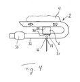
- Fig. 4 depicts schematically an exhaust post-treatment device 2 for a vehicle 4 according to a fourth embodiment of the invention, which device 2 comprises a Peltier element 6.
- the device 2 likewise comprises a supply device 16 for supply to the exhaust gases 20 of liquid reducing agent 18 intended for reduction of nitrogen oxides present in them.
- the embodiment depicted in Fig. 4 differs from that described with respect to Fig. 1 in that in this case the heat absorption side 28 of the Peltier element 6 is upstream of its heat delivery side 30 and is adjacent to the outside of an exhaust pipe 32.
- This embodiment further differs from that described with respect to Fig. 1 in that the heat delivery side 30 of the Peltier element 6 is at least partly situated within an exhaust pipe 32 so that it has within the exhaust pipe 32 a surface 31 which is warmed locally.
- the description with respect to Fig. 1 applies also, e.g. as regards a possible control unit, to the embodiment depicted in Fig. 2 but any catalyst 38 has to be situated downstream of the supply device 16 for supply of liquid reducing agent 18 to the exhaust gases 20.
- the liquid reducing agent 18 is preferably kept warm enough not to freeze, which in the case of "Ad Blue” would take place at about -11°C.
- FIGS 5 and 6 illustrate examples of the method for post-treatment of exhaust gases.
- Fig. 5 is a schematic flowchart of a method according to an embodiment of the invention, and the reference notations 2, 4, 18, 20, 31, 32 used here are those of Figures 1-4 .
- the method for post-treatment of exhaust gases from vehicles by 100 supplying liquid reducing agent 18 to the exhaust gases 20 in an exhaust pipe 32 in order thereby to reduce nitrogen oxides present in the exhaust gases 20 of the vehicle 4 comprises also the step of 200 locally warming a surface 31 within the exhaust pipe 32 with an exhaust post-treatment device 2 comprising a Peltier element 6 by using thermal energy from the exhaust gases 20 to vaporise liquid reducing agent 18 which reaches the surface 31, and thereby prevent formation of deposits of reducing agent within the exhaust pipe.
- Fig. 6 is a schematic flowchart of a method according to a further embodiment of the invention, and the reference notations 6, 20, 28, 30, 31, 32 used here are those of Figures 1-4 .
- the embodiment in Fig. 6 comprises not only the steps of Fig. 5 but also those of using the exhaust gases 20 to warm 110 the heat absorption side 28 of the Peltier element 6, 120 applying a direct current across the Peltier element 6, and 200 delivering thermal energy to the surface 31 within the exhaust pipe 32 from the heat delivery side 30 of the Peltier element 6.
- the invention is in no way restricted to the embodiments described but may be varied freely within the scopes of the claims. Parts from the various embodiments may be combined.
- the heat absorption side 28 of the Peltier element 6 may thus be situated adjacent to the outside of the exhaust pipe 32 or at least partly within the exhaust pipe 32.
- the absorption side 28 of the Peltier element 6 may thus be situated either downstream or upstream of the supply device 16 for supply of liquid reducing agent 18 to the exhaust gases 20 in the exhaust pipe 32, as seen in their direction of flow, but a downstream location is advisable purely functionally in that having the heat absorption side 28 of the Peltier element 6 downstream of the supply device 16 for supply of liquid reducing agent 18 means that energy is only absorbed from the exhaust gases 20 after the supply of liquid reducing agent 18 to the exhaust gases 20, thereby avoiding a corresponding lowering of the exhaust temperature before supply of liquid reducing agent 18, which would be disadvantageous for its vaporisation.
- the heat delivery side 30 of the Peltier element 6 might thus be situated either adjacent to the outside of the exhaust pipe 32 or at least partly within the exhaust pipe 32.
- the surface 31 which is warmed might thus be part of the inside of the exhaust pipe 32 or be a surface of the heat delivery side 30 of the Peltier element 6 which is situated within the exhaust pipe 32 or be some other surface within the exhaust pipe which is in thermally conductive contact with the heat delivery side 30 of the Peltier element 6.
Landscapes
- Engineering & Computer Science (AREA)
- Chemical & Material Sciences (AREA)
- Chemical Kinetics & Catalysis (AREA)
- Combustion & Propulsion (AREA)
- Mechanical Engineering (AREA)
- General Engineering & Computer Science (AREA)
- Health & Medical Sciences (AREA)
- Toxicology (AREA)
- Exhaust Gas After Treatment (AREA)
Claims (12)
- Abgasnachbehandlungsvorrichtung (2) für ein Fahrzeug (4), die dazu eingerichtet ist, in den Abgasen (20) des Fahrzeugs (4) vorhandene Stickstoffoxide durch Zuführen von flüssigem Reduktionsmittel (18) an die Abgase (20) in einem Abgasrohr (32) zu reduzieren, dadurch gekennzeichnet, dass die Vorrichtung (2) ein Peltier-Element (6) zum Ableiten von Wärmeenergie von den Abgasen (20) umfasst, indem Wärmeenergie auf einer Seite (28) des Peltier-Elements absorbiert wird, und indem die andere Seite (30) des Peltier-Elements (6) dazu eingerichtet ist, eine Oberfläche (31) in dem Abgasrohr (32) lokal zu erwärmen, indem Wärmeenergie von dem Peltier-Element (6) an die Oberfläche (31) abgegeben wird, um das flüssige Reduktionsmittel (18) zu verdampfen, das an die Oberfläche (31) gelangt, und dadurch ein Bilden von Ablagerungen des Reduktionsmittels in dem Abgasrohr zu vermeiden, und dass das Peltier-Element (6) mit einer Gleichstromquelle (14) verbunden ist, und dass Strom von diesem die Wärme von einer Seite (28) des Peltier-Elements (6) zu der anderen Seite (30) des Peltier-Elements (6) ableitet.
- Abgasnachbehandlungsvorrichtung (2) nach Anspruch 1, dadurch gekennzeichnet, dass das Peltier-Element (6) wenigstens zwei Elektroden (8, 10) umfasst, die aus unterschiedlichen halbleitenden Metallen hergestellt sind, wobei jede zweite Elektrode (8) von einem N-Typ ist und die alternierenden Elektroden (10) von einem P-Typ sind, wobei die Elektroden (8, 10) derart angeordnet sind, dass sie sich von einer Seite (28) des Peltier-Elements (6) zu der anderen Seite (30) des Peltier-Elements (6) erstrecken und mittels Leitern (12) in Reihenschaltung mit der Gleichstromquelle (14) verbunden sind, sodass ein Schließen des elektrischen Schaltkreises Elektronen in der N-Typ Elektrode dazu veranlasst, sich in eine dem Strom entgegengesetzte Richtung zu bewegen, und Löcher in der P-Type Elektrode veranlasst, sich in die Richtung des Stroms zu bewegen, wobei beide von diesen Wärme von einer Seite (28) des Peltier-Elements (6) zu der anderen Seite (30) des Peltier-Elements (6) ableiten.
- Abgasnachbehandlungsvorrichtung (2) nach einem der Ansprüche 1 bis 2, dadurch gekennzeichnet, dass das flüssige Reduktionsmittel (18) eine flüssige Harnstofflösung ist.
- Abgasnachbehandlungsvorrichtung (2) nach einem der Ansprüche 1 bis 3 dadurch gekennzeichnet, dass die Wärmeenergieabsorptionsseite (28) des Peltier-Elements (6) zumindest abschnittsweise in dem Abgasrohr (32) angeordnet ist.
- Abgasnachbehandlungsvorrichtung (2) nach einem der Ansprüche 1 bis 3, dadurch gekennzeichnet, dass die Wärmeenergieabsorptionsseite (28) des Peltier-Elements (6) an die Außenseite des Abgasrohrs (32) angrenzend angeordnet ist.
- Abgasnachbehandlungsvorrichtung (2) nach einem der Ansprüche 1 bis 5, dadurch gekennzeichnet, dass die Wärmeenergieabsorptionsseite (28) des Peltier-Elements (6) der Zuführvorrichtung (16) zum Zuführen von flüssigem Reduktionsmittel (18) an die Abgase (20) in dem Abgasrohr (32) nachgelagert oder vorgelagert angeordnet ist, betrachtet in Richtung der Strömung der Abgase (20).
- Abgasnachbehandlungsvorrichtung (2) nach einem der Ansprüche 1 bis 6, dadurch gekennzeichnet, dass die Wärmeenergiezuführseite (30) des Peltier-Elements (6) an die Außenseite des Abgasrohrs (32) angrenzend angeordnet ist.
- Abgasnachbehandlungsvorrichtung (2) nach einem der Ansprüche 1 bis 6, dadurch gekennzeichnet, dass die Wärmeenergiezuführseite (30) des Peltier-Elements (6) zumindest abschnittsweise in dem Abgasrohr (32) angeordnet ist.
- Abgasnachbehandlungsvorrichtung (2) nach Anspruch 8, dadurch gekennzeichnet, dass die Oberfläche (31), die in dem Abgasrohr lokal erwärmt wird, eine Oberfläche der Wärmeenergiezuführseite (30) des Peltier-Elements (6) ist, die in dem Abgasrohr (32) angeordnet ist.
- Abgasnachbehandlungsvorrichtung (2) nach einem der Ansprüche 1 bis 9, dadurch gekennzeichnet, dass in dem Abgasrohr (32) ein der Zuführvorrichtung (16) zum Zuführen von flüssigem Reduktionsmittel (18) nachgelagerter Katalysator (38) vorgesehen ist, betrachtet in Richtung der Strömung der Abgase (20).
- Abgasnachbehandlungsvorrichtung (2) nach einem der Ansprüche 1 bis 10, dadurch gekennzeichnet, dass wenigstens eine Steuerungseinheit (34) vorgesehen ist, um das Peltier-Element (6) und das Zuführen von flüssigem Reduktionsmittel (18) zu steuern.
- Verfahren zum Nachbehandeln von Abgasen von Fahrzeugen durch Zuführen von flüssigem Reduktionsmittel (18) an die Abgase (20) in einem Abgasrohr (32), um in den Abgasen (20) des Fahrzeugs (4) vorhandene Stickstoffoxide zu reduzieren, gekennzeichnet durch den Schritt: lokales Erwärmen (200) einer Oberfläche (31) in dem Abgasrohr (32) mit einer Abgasnachbehandlungsvorrichtung (2), die ein Peltier-Element (6) umfasst, durch Verwenden von Wärmeenergie von den Abgasen (20), um flüssiges Reduktionsmittel (18) zu verdampfen, das an die Oberfläche (31) gelangt, und dabei das Bilden von Ablagerungen des Reduktionsmittels in dem Abgasrohr zu vermeiden, und durch die Schritte: Verwenden der Abgase (20), um die Wärmeenergieabsorptionsseite (28) des Peltier-Elements (6) zu erwärmen (110), Anlegen (120) eines Gleichstroms (A) über das Peltier-Element (6), und Zuführen (200) von Wärmenergie zu einer Oberfläche (31) in dem Abgasrohr (32) von der Wärmeenergiezuführseite (30) des Peltier-Elements (6).
Applications Claiming Priority (2)
| Application Number | Priority Date | Filing Date | Title |
|---|---|---|---|
| SE1051161A SE535355C2 (sv) | 2010-11-08 | 2010-11-08 | Avgasefterbehandlingsanordning och förfarande för efterbehandling av avgaser |
| PCT/SE2011/051244 WO2012064253A1 (en) | 2010-11-08 | 2011-10-18 | Exhaust post-treatment device and method for a vehicle, with a reductant vaporising surface being warmed by a peltier element. |
Publications (3)
| Publication Number | Publication Date |
|---|---|
| EP2638258A1 EP2638258A1 (de) | 2013-09-18 |
| EP2638258A4 EP2638258A4 (de) | 2014-07-09 |
| EP2638258B1 true EP2638258B1 (de) | 2015-07-29 |
Family
ID=46051192
Family Applications (1)
| Application Number | Title | Priority Date | Filing Date |
|---|---|---|---|
| EP11840488.8A Active EP2638258B1 (de) | 2010-11-08 | 2011-10-18 | Abgasnachbearbeitungsvorrichtung und -verfahren für ein fahrzeug mit einer durch ein peltier-element erwärmten reduktionsmittelverdampfungsoberfläche |
Country Status (9)
| Country | Link |
|---|---|
| US (1) | US9062582B2 (de) |
| EP (1) | EP2638258B1 (de) |
| JP (1) | JP5635705B2 (de) |
| KR (1) | KR20130140056A (de) |
| CN (1) | CN103189609B (de) |
| BR (1) | BR112013009358A2 (de) |
| RU (1) | RU2541361C2 (de) |
| SE (1) | SE535355C2 (de) |
| WO (1) | WO2012064253A1 (de) |
Families Citing this family (20)
| Publication number | Priority date | Publication date | Assignee | Title |
|---|---|---|---|---|
| JP6136960B2 (ja) * | 2014-01-31 | 2017-05-31 | トヨタ自動車株式会社 | 内燃機関の排気系構造 |
| WO2017127512A1 (en) * | 2016-01-19 | 2017-07-27 | The Regents Of The University Of Michigan | Thermoelectric micro-module with high leg density for energy harvesting and cooling applications |
| ITUA20163109A1 (it) * | 2016-05-03 | 2017-11-03 | Fpt Motorenforschung Ag | Sistema di gestione termica di un sistema di post trattamento dei gas esausti (ats) |
| US10295489B2 (en) | 2016-09-12 | 2019-05-21 | Ecolab Usa Inc. | Deposit monitor |
| US10816285B2 (en) * | 2017-02-24 | 2020-10-27 | Ecolab Usa Inc. | Thermoelectric deposit monitor |
| US10337380B2 (en) | 2017-07-07 | 2019-07-02 | Faurecia Emissions Control Technologies, Usa, Llc | Mixer for a vehicle exhaust system |
| US10239018B2 (en) * | 2017-07-13 | 2019-03-26 | Sisu Energy & Environmental, LLC | Exhaust gas reagent vaporization system |
| US10577995B2 (en) | 2017-08-25 | 2020-03-03 | Faurecia Emissions Control Technologies, Usa, Llc | Double wall mixer with active heat transfer |
| DE102017124276A1 (de) * | 2017-10-18 | 2019-04-18 | Eberspächer Exhaust Technology GmbH & Co. KG | Mischanordnung |
| US10316721B1 (en) | 2018-04-23 | 2019-06-11 | Faurecia Emissions Control Technologies, Usa, Llc | High efficiency mixer for vehicle exhaust system |
| US10287948B1 (en) | 2018-04-23 | 2019-05-14 | Faurecia Emissions Control Technologies, Usa, Llc | High efficiency mixer for vehicle exhaust system |
| US10787946B2 (en) | 2018-09-19 | 2020-09-29 | Faurecia Emissions Control Technologies, Usa, Llc | Heated dosing mixer |
| US11953458B2 (en) | 2019-03-14 | 2024-04-09 | Ecolab Usa Inc. | Systems and methods utilizing sensor surface functionalization |
| US11193413B2 (en) | 2019-12-12 | 2021-12-07 | Faurecia Emissions Control Technologies, Usa, Llc | Exhaust aftertreatment system with virtual temperature determination and control |
| US20210222601A1 (en) * | 2020-01-22 | 2021-07-22 | Cnh Industrial America Llc | System for cooling a diesel exhaust fluid |
| US11319853B2 (en) | 2020-03-31 | 2022-05-03 | Faurecia Emissions Control Technologies, Usa, Llc | Automotive exhaust aftertreatment system with doser |
| US11092054B1 (en) | 2020-04-29 | 2021-08-17 | Faurecia Emissions Control Technologies, Usa, Llc | Flash-boiling doser with thermal transfer helix |
| US11511239B2 (en) | 2020-04-29 | 2022-11-29 | Faurecia Emissions Control Technologies, Usa, Llc | Heated flash-boiling doser with integrated helix |
| US11384667B2 (en) | 2020-05-29 | 2022-07-12 | Faurecia Emissions Control Technologies, Usa, Llc | Exhaust aftertreatment system with heated dosing control |
| US11225894B1 (en) | 2020-06-30 | 2022-01-18 | Faurecia Emissions Control Technologies, Usa, Llc | Exhaust aftertreatment system with thermally controlled reagent doser |
Family Cites Families (22)
| Publication number | Priority date | Publication date | Assignee | Title |
|---|---|---|---|---|
| DE4438335A1 (de) * | 1994-10-27 | 1996-05-02 | Bosch Gmbh Robert | Brennstoffeinspritzvorrichtung für eine Brennkraftmaschine |
| US5968456A (en) * | 1997-05-09 | 1999-10-19 | Parise; Ronald J. | Thermoelectric catalytic power generator with preheat |
| JPH11257064A (ja) * | 1998-03-10 | 1999-09-21 | Nissan Motor Co Ltd | 内燃機関の排気管冷却装置 |
| WO1999067770A2 (en) * | 1998-06-25 | 1999-12-29 | Koninklijke Philips Electronics N.V. | Display device with temperature-stabilizing means |
| DE10041955A1 (de) * | 2000-08-25 | 2002-03-07 | Audi Ag | Kraftfahrzeugbauteil |
| JP4290027B2 (ja) * | 2004-02-02 | 2009-07-01 | 日産ディーゼル工業株式会社 | 排気浄化装置 |
| WO2005073528A1 (ja) * | 2004-02-02 | 2005-08-11 | Nissan Diesel Motor Co., Ltd. | エンジンの排気浄化装置 |
| JP2005223132A (ja) * | 2004-02-05 | 2005-08-18 | Toyota Motor Corp | 内燃機関の熱電発電装置 |
| JP4085998B2 (ja) * | 2004-03-22 | 2008-05-14 | トヨタ自動車株式会社 | 排熱回収装置 |
| JP4290081B2 (ja) * | 2004-07-02 | 2009-07-01 | 日産ディーゼル工業株式会社 | 排気浄化装置 |
| US20070048204A1 (en) * | 2005-09-01 | 2007-03-01 | Rahul Mital | Flash injector for NH3-SCR NOx aftertreatment |
| DE102006023148A1 (de) * | 2006-05-16 | 2007-11-22 | Emitec Gesellschaft Für Emissionstechnologie Mbh | Vorrichtung zur Aufbereitung von Abgas einer Verbrennungskraftmaschine |
| JP2008196479A (ja) * | 2007-02-09 | 2008-08-28 | Sulzer Chemtech Ag | 排気ガス浄化システム |
| US8061123B2 (en) * | 2007-10-30 | 2011-11-22 | Caterpillar Inc. | Method and system of thermal management in an exhaust system |
| US20090139207A1 (en) * | 2007-11-30 | 2009-06-04 | Caterpillar Inc. | Thermo-electric auxiliary power unit |
| DE102007058768A1 (de) | 2007-12-06 | 2009-06-10 | Robert Bosch Gmbh | Abgasnachbehandlungsanordnung mit Reduktionsmittelspeicher und Verfahren zur Nachbehandlung von Abgasen |
| US7921640B2 (en) * | 2007-12-14 | 2011-04-12 | Gm Global Technology Operations, Llc | Exhaust gas waste heat recovery |
| FR2925583A3 (fr) | 2007-12-21 | 2009-06-26 | Renault Sas | Dispositif de depollution des gaz d'echappement d'un moteur a combustion interne |
| EP2078834B1 (de) | 2008-01-10 | 2014-06-04 | Haldor Topsoe A/S | Verfahren und System zur Reinigung von Abgas aus Dieselmotoren |
| WO2009106609A1 (de) * | 2008-02-29 | 2009-09-03 | Emitec Gesellschaft Für Emissionstechnologie Mbh | Verdampfungseinheit zur erzeugung eines mindestens einen reduktionsmittelvorläufer und/oder ein reduktionsmittel umfassenden gases |
| JP5107787B2 (ja) * | 2008-04-24 | 2012-12-26 | 三菱ふそうトラック・バス株式会社 | 排気浄化装置 |
| DE102008063861A1 (de) * | 2008-12-19 | 2010-07-01 | Emcon Technologies Germany (Augsburg) Gmbh | Abgasbehandlungsvorrichtung |
-
2010
- 2010-11-08 SE SE1051161A patent/SE535355C2/sv unknown
-
2011
- 2011-10-18 BR BR112013009358A patent/BR112013009358A2/pt not_active IP Right Cessation
- 2011-10-18 WO PCT/SE2011/051244 patent/WO2012064253A1/en active Application Filing
- 2011-10-18 KR KR1020137014590A patent/KR20130140056A/ko not_active Application Discontinuation
- 2011-10-18 EP EP11840488.8A patent/EP2638258B1/de active Active
- 2011-10-18 CN CN201180053566.5A patent/CN103189609B/zh not_active Expired - Fee Related
- 2011-10-18 US US13/879,634 patent/US9062582B2/en not_active Expired - Fee Related
- 2011-10-18 RU RU2013126427/06A patent/RU2541361C2/ru not_active IP Right Cessation
- 2011-10-18 JP JP2013537637A patent/JP5635705B2/ja not_active Expired - Fee Related
Also Published As
| Publication number | Publication date |
|---|---|
| SE535355C2 (sv) | 2012-07-03 |
| CN103189609A (zh) | 2013-07-03 |
| SE1051161A1 (sv) | 2012-05-09 |
| RU2541361C2 (ru) | 2015-02-10 |
| RU2013126427A (ru) | 2014-12-20 |
| BR112013009358A2 (pt) | 2016-08-02 |
| WO2012064253A1 (en) | 2012-05-18 |
| CN103189609B (zh) | 2015-07-15 |
| JP2013543945A (ja) | 2013-12-09 |
| US9062582B2 (en) | 2015-06-23 |
| KR20130140056A (ko) | 2013-12-23 |
| EP2638258A4 (de) | 2014-07-09 |
| US20130232956A1 (en) | 2013-09-12 |
| EP2638258A1 (de) | 2013-09-18 |
| JP5635705B2 (ja) | 2014-12-03 |
Similar Documents
| Publication | Publication Date | Title |
|---|---|---|
| EP2638258B1 (de) | Abgasnachbearbeitungsvorrichtung und -verfahren für ein fahrzeug mit einer durch ein peltier-element erwärmten reduktionsmittelverdampfungsoberfläche | |
| EP3102801B1 (de) | Systemaufbau einer abgasnachbehandlug für verbrennungsmotoren | |
| JP4888480B2 (ja) | 排気浄化システムの制御装置 | |
| CN102016251B (zh) | 用于输送还原剂的设备和用于制造机动车的方法 | |
| KR101199272B1 (ko) | 첨가제를 저장하여 엔진의 배기 가스에 이를 분사하는방법과 시스템 | |
| JP6045034B2 (ja) | 排ガス処理装置の作動方法 | |
| US20170107881A1 (en) | Device for providing a liquid additive | |
| US9879582B2 (en) | Method for starting the operation of a device for providing a liquid additive | |
| JP2015152010A (ja) | 内燃機関 | |
| US20170159523A1 (en) | Heater for a device for providing a liquid additive | |
| US20130000729A1 (en) | Def pump and tank thawing system and method | |
| US8438838B2 (en) | Fuel-fired burner and heat exchanger system for heating a NOx reducing agent supply tank | |
| JP2011080397A (ja) | 内燃機関の排気浄化装置 | |
| JP4087350B2 (ja) | エンジンの排気浄化装置 | |
| EP2917527A1 (de) | Vorrichtung zur bereitstellung eines flüssigen zusatzstoffs und verfahren zum erhitzen des zusatzstoffs | |
| GB2533099A (en) | Method for providing heating to a diesel exhaust fluid (DEF) tank and diesel exhaust fluid (DEF) tank | |
| US9279354B2 (en) | Control unit for urea-water adding device | |
| US20160076424A1 (en) | Coolant heating method for releasing reductant | |
| JP2015502490A (ja) | 排ガス処理剤注入ユニットを有する排気処理装置 | |
| JP6015579B2 (ja) | 蓄熱装置 | |
| SE1450417A1 (sv) | Avgasefterbehandlingsarrangemang och ett motorfordon innefattande ett sådant avgasefterbehandlingsarrangemang | |
| WO2020076231A1 (en) | Heating arrangement | |
| SE541586C2 (en) | An arrangement for heating and providing a reducing agent to an exhaust treatment device |
Legal Events
| Date | Code | Title | Description |
|---|---|---|---|
| PUAI | Public reference made under article 153(3) epc to a published international application that has entered the european phase |
Free format text: ORIGINAL CODE: 0009012 |
|
| 17P | Request for examination filed |
Effective date: 20130610 |
|
| AK | Designated contracting states |
Kind code of ref document: A1 Designated state(s): AL AT BE BG CH CY CZ DE DK EE ES FI FR GB GR HR HU IE IS IT LI LT LU LV MC MK MT NL NO PL PT RO RS SE SI SK SM TR |
|
| DAX | Request for extension of the european patent (deleted) | ||
| A4 | Supplementary search report drawn up and despatched |
Effective date: 20140606 |
|
| RIC1 | Information provided on ipc code assigned before grant |
Ipc: F01N 3/20 20060101AFI20140602BHEP Ipc: F01N 13/08 20100101ALI20140602BHEP Ipc: F01N 9/00 20060101ALI20140602BHEP |
|
| REG | Reference to a national code |
Ref country code: DE Ref legal event code: R079 Ref document number: 602011018355 Country of ref document: DE Free format text: PREVIOUS MAIN CLASS: F01N0003200000 Ipc: F01N0003180000 |
|
| GRAP | Despatch of communication of intention to grant a patent |
Free format text: ORIGINAL CODE: EPIDOSNIGR1 |
|
| RIC1 | Information provided on ipc code assigned before grant |
Ipc: F01N 3/20 20060101AFI20150130BHEP |
|
| RIC1 | Information provided on ipc code assigned before grant |
Ipc: F01N 3/18 20060101AFI20150211BHEP |
|
| INTG | Intention to grant announced |
Effective date: 20150303 |
|
| GRAS | Grant fee paid |
Free format text: ORIGINAL CODE: EPIDOSNIGR3 |
|
| GRAA | (expected) grant |
Free format text: ORIGINAL CODE: 0009210 |
|
| AK | Designated contracting states |
Kind code of ref document: B1 Designated state(s): AL AT BE BG CH CY CZ DE DK EE ES FI FR GB GR HR HU IE IS IT LI LT LU LV MC MK MT NL NO PL PT RO RS SE SI SK SM TR |
|
| REG | Reference to a national code |
Ref country code: GB Ref legal event code: FG4D |
|
| REG | Reference to a national code |
Ref country code: CH Ref legal event code: EP |
|
| REG | Reference to a national code |
Ref country code: AT Ref legal event code: REF Ref document number: 739486 Country of ref document: AT Kind code of ref document: T Effective date: 20150815 |
|
| REG | Reference to a national code |
Ref country code: IE Ref legal event code: FG4D |
|
| REG | Reference to a national code |
Ref country code: DE Ref legal event code: R096 Ref document number: 602011018355 Country of ref document: DE |
|
| REG | Reference to a national code |
Ref country code: AT Ref legal event code: MK05 Ref document number: 739486 Country of ref document: AT Kind code of ref document: T Effective date: 20150729 |
|
| REG | Reference to a national code |
Ref country code: LT Ref legal event code: MG4D |
|
| REG | Reference to a national code |
Ref country code: NL Ref legal event code: MP Effective date: 20150729 |
|
| PG25 | Lapsed in a contracting state [announced via postgrant information from national office to epo] |
Ref country code: GR Free format text: LAPSE BECAUSE OF FAILURE TO SUBMIT A TRANSLATION OF THE DESCRIPTION OR TO PAY THE FEE WITHIN THE PRESCRIBED TIME-LIMIT Effective date: 20151030 Ref country code: LT Free format text: LAPSE BECAUSE OF FAILURE TO SUBMIT A TRANSLATION OF THE DESCRIPTION OR TO PAY THE FEE WITHIN THE PRESCRIBED TIME-LIMIT Effective date: 20150729 Ref country code: FI Free format text: LAPSE BECAUSE OF FAILURE TO SUBMIT A TRANSLATION OF THE DESCRIPTION OR TO PAY THE FEE WITHIN THE PRESCRIBED TIME-LIMIT Effective date: 20150729 Ref country code: NO Free format text: LAPSE BECAUSE OF FAILURE TO SUBMIT A TRANSLATION OF THE DESCRIPTION OR TO PAY THE FEE WITHIN THE PRESCRIBED TIME-LIMIT Effective date: 20151029 Ref country code: LV Free format text: LAPSE BECAUSE OF FAILURE TO SUBMIT A TRANSLATION OF THE DESCRIPTION OR TO PAY THE FEE WITHIN THE PRESCRIBED TIME-LIMIT Effective date: 20150729 |
|
| PG25 | Lapsed in a contracting state [announced via postgrant information from national office to epo] |
Ref country code: RS Free format text: LAPSE BECAUSE OF FAILURE TO SUBMIT A TRANSLATION OF THE DESCRIPTION OR TO PAY THE FEE WITHIN THE PRESCRIBED TIME-LIMIT Effective date: 20150729 Ref country code: PT Free format text: LAPSE BECAUSE OF FAILURE TO SUBMIT A TRANSLATION OF THE DESCRIPTION OR TO PAY THE FEE WITHIN THE PRESCRIBED TIME-LIMIT Effective date: 20151130 Ref country code: AT Free format text: LAPSE BECAUSE OF FAILURE TO SUBMIT A TRANSLATION OF THE DESCRIPTION OR TO PAY THE FEE WITHIN THE PRESCRIBED TIME-LIMIT Effective date: 20150729 Ref country code: IS Free format text: LAPSE BECAUSE OF FAILURE TO SUBMIT A TRANSLATION OF THE DESCRIPTION OR TO PAY THE FEE WITHIN THE PRESCRIBED TIME-LIMIT Effective date: 20151129 Ref country code: PL Free format text: LAPSE BECAUSE OF FAILURE TO SUBMIT A TRANSLATION OF THE DESCRIPTION OR TO PAY THE FEE WITHIN THE PRESCRIBED TIME-LIMIT Effective date: 20150729 Ref country code: HR Free format text: LAPSE BECAUSE OF FAILURE TO SUBMIT A TRANSLATION OF THE DESCRIPTION OR TO PAY THE FEE WITHIN THE PRESCRIBED TIME-LIMIT Effective date: 20150729 Ref country code: SE Free format text: LAPSE BECAUSE OF FAILURE TO SUBMIT A TRANSLATION OF THE DESCRIPTION OR TO PAY THE FEE WITHIN THE PRESCRIBED TIME-LIMIT Effective date: 20150729 Ref country code: ES Free format text: LAPSE BECAUSE OF FAILURE TO SUBMIT A TRANSLATION OF THE DESCRIPTION OR TO PAY THE FEE WITHIN THE PRESCRIBED TIME-LIMIT Effective date: 20150729 |
|
| PG25 | Lapsed in a contracting state [announced via postgrant information from national office to epo] |
Ref country code: NL Free format text: LAPSE BECAUSE OF FAILURE TO SUBMIT A TRANSLATION OF THE DESCRIPTION OR TO PAY THE FEE WITHIN THE PRESCRIBED TIME-LIMIT Effective date: 20150729 |
|
| PG25 | Lapsed in a contracting state [announced via postgrant information from national office to epo] |
Ref country code: IT Free format text: LAPSE BECAUSE OF FAILURE TO SUBMIT A TRANSLATION OF THE DESCRIPTION OR TO PAY THE FEE WITHIN THE PRESCRIBED TIME-LIMIT Effective date: 20150729 Ref country code: DK Free format text: LAPSE BECAUSE OF FAILURE TO SUBMIT A TRANSLATION OF THE DESCRIPTION OR TO PAY THE FEE WITHIN THE PRESCRIBED TIME-LIMIT Effective date: 20150729 Ref country code: EE Free format text: LAPSE BECAUSE OF FAILURE TO SUBMIT A TRANSLATION OF THE DESCRIPTION OR TO PAY THE FEE WITHIN THE PRESCRIBED TIME-LIMIT Effective date: 20150729 Ref country code: CZ Free format text: LAPSE BECAUSE OF FAILURE TO SUBMIT A TRANSLATION OF THE DESCRIPTION OR TO PAY THE FEE WITHIN THE PRESCRIBED TIME-LIMIT Effective date: 20150729 Ref country code: SK Free format text: LAPSE BECAUSE OF FAILURE TO SUBMIT A TRANSLATION OF THE DESCRIPTION OR TO PAY THE FEE WITHIN THE PRESCRIBED TIME-LIMIT Effective date: 20150729 |
|
| REG | Reference to a national code |
Ref country code: DE Ref legal event code: R097 Ref document number: 602011018355 Country of ref document: DE |
|
| PG25 | Lapsed in a contracting state [announced via postgrant information from national office to epo] |
Ref country code: RO Free format text: LAPSE BECAUSE OF FAILURE TO SUBMIT A TRANSLATION OF THE DESCRIPTION OR TO PAY THE FEE WITHIN THE PRESCRIBED TIME-LIMIT Effective date: 20150729 Ref country code: LU Free format text: LAPSE BECAUSE OF FAILURE TO SUBMIT A TRANSLATION OF THE DESCRIPTION OR TO PAY THE FEE WITHIN THE PRESCRIBED TIME-LIMIT Effective date: 20151018 |
|
| REG | Reference to a national code |
Ref country code: CH Ref legal event code: PL |
|
| PLBE | No opposition filed within time limit |
Free format text: ORIGINAL CODE: 0009261 |
|
| STAA | Information on the status of an ep patent application or granted ep patent |
Free format text: STATUS: NO OPPOSITION FILED WITHIN TIME LIMIT |
|
| GBPC | Gb: european patent ceased through non-payment of renewal fee |
Effective date: 20151029 |
|
| PG25 | Lapsed in a contracting state [announced via postgrant information from national office to epo] |
Ref country code: MC Free format text: LAPSE BECAUSE OF FAILURE TO SUBMIT A TRANSLATION OF THE DESCRIPTION OR TO PAY THE FEE WITHIN THE PRESCRIBED TIME-LIMIT Effective date: 20150729 |
|
| 26N | No opposition filed |
Effective date: 20160502 |
|
| REG | Reference to a national code |
Ref country code: IE Ref legal event code: MM4A |
|
| PG25 | Lapsed in a contracting state [announced via postgrant information from national office to epo] |
Ref country code: GB Free format text: LAPSE BECAUSE OF NON-PAYMENT OF DUE FEES Effective date: 20151029 Ref country code: LI Free format text: LAPSE BECAUSE OF NON-PAYMENT OF DUE FEES Effective date: 20151031 Ref country code: CH Free format text: LAPSE BECAUSE OF NON-PAYMENT OF DUE FEES Effective date: 20151031 |
|
| REG | Reference to a national code |
Ref country code: FR Ref legal event code: ST Effective date: 20160630 |
|
| PG25 | Lapsed in a contracting state [announced via postgrant information from national office to epo] |
Ref country code: SI Free format text: LAPSE BECAUSE OF FAILURE TO SUBMIT A TRANSLATION OF THE DESCRIPTION OR TO PAY THE FEE WITHIN THE PRESCRIBED TIME-LIMIT Effective date: 20150729 Ref country code: FR Free format text: LAPSE BECAUSE OF NON-PAYMENT OF DUE FEES Effective date: 20151102 |
|
| PG25 | Lapsed in a contracting state [announced via postgrant information from national office to epo] |
Ref country code: IE Free format text: LAPSE BECAUSE OF NON-PAYMENT OF DUE FEES Effective date: 20151018 |
|
| PG25 | Lapsed in a contracting state [announced via postgrant information from national office to epo] |
Ref country code: BE Free format text: LAPSE BECAUSE OF FAILURE TO SUBMIT A TRANSLATION OF THE DESCRIPTION OR TO PAY THE FEE WITHIN THE PRESCRIBED TIME-LIMIT Effective date: 20150729 |
|
| PG25 | Lapsed in a contracting state [announced via postgrant information from national office to epo] |
Ref country code: BG Free format text: LAPSE BECAUSE OF FAILURE TO SUBMIT A TRANSLATION OF THE DESCRIPTION OR TO PAY THE FEE WITHIN THE PRESCRIBED TIME-LIMIT Effective date: 20150729 Ref country code: SM Free format text: LAPSE BECAUSE OF FAILURE TO SUBMIT A TRANSLATION OF THE DESCRIPTION OR TO PAY THE FEE WITHIN THE PRESCRIBED TIME-LIMIT Effective date: 20150729 Ref country code: HU Free format text: LAPSE BECAUSE OF FAILURE TO SUBMIT A TRANSLATION OF THE DESCRIPTION OR TO PAY THE FEE WITHIN THE PRESCRIBED TIME-LIMIT; INVALID AB INITIO Effective date: 20111018 |
|
| PG25 | Lapsed in a contracting state [announced via postgrant information from national office to epo] |
Ref country code: CY Free format text: LAPSE BECAUSE OF FAILURE TO SUBMIT A TRANSLATION OF THE DESCRIPTION OR TO PAY THE FEE WITHIN THE PRESCRIBED TIME-LIMIT Effective date: 20150729 |
|
| PG25 | Lapsed in a contracting state [announced via postgrant information from national office to epo] |
Ref country code: MT Free format text: LAPSE BECAUSE OF FAILURE TO SUBMIT A TRANSLATION OF THE DESCRIPTION OR TO PAY THE FEE WITHIN THE PRESCRIBED TIME-LIMIT Effective date: 20150729 |
|
| PG25 | Lapsed in a contracting state [announced via postgrant information from national office to epo] |
Ref country code: MK Free format text: LAPSE BECAUSE OF FAILURE TO SUBMIT A TRANSLATION OF THE DESCRIPTION OR TO PAY THE FEE WITHIN THE PRESCRIBED TIME-LIMIT Effective date: 20150729 Ref country code: TR Free format text: LAPSE BECAUSE OF FAILURE TO SUBMIT A TRANSLATION OF THE DESCRIPTION OR TO PAY THE FEE WITHIN THE PRESCRIBED TIME-LIMIT Effective date: 20150729 |
|
| PG25 | Lapsed in a contracting state [announced via postgrant information from national office to epo] |
Ref country code: AL Free format text: LAPSE BECAUSE OF FAILURE TO SUBMIT A TRANSLATION OF THE DESCRIPTION OR TO PAY THE FEE WITHIN THE PRESCRIBED TIME-LIMIT Effective date: 20150729 |
|
| PGFP | Annual fee paid to national office [announced via postgrant information from national office to epo] |
Ref country code: DE Payment date: 20230830 Year of fee payment: 13 |