EP2637730B1 - Dispositifs intravaginaux pour l'administration régulée de lubrifiants - Google Patents
Dispositifs intravaginaux pour l'administration régulée de lubrifiants Download PDFInfo
- Publication number
- EP2637730B1 EP2637730B1 EP11839939.3A EP11839939A EP2637730B1 EP 2637730 B1 EP2637730 B1 EP 2637730B1 EP 11839939 A EP11839939 A EP 11839939A EP 2637730 B1 EP2637730 B1 EP 2637730B1
- Authority
- EP
- European Patent Office
- Prior art keywords
- ivr
- water
- segment
- lubricant
- ring
- Prior art date
- Legal status (The legal status is an assumption and is not a legal conclusion. Google has not performed a legal analysis and makes no representation as to the accuracy of the status listed.)
- Active
Links
- 239000000314 lubricant Substances 0.000 title claims description 145
- PEDCQBHIVMGVHV-UHFFFAOYSA-N Glycerine Chemical compound OCC(O)CO PEDCQBHIVMGVHV-UHFFFAOYSA-N 0.000 claims description 315
- XLYOFNOQVPJJNP-UHFFFAOYSA-N water Substances O XLYOFNOQVPJJNP-UHFFFAOYSA-N 0.000 claims description 170
- 239000004814 polyurethane Substances 0.000 claims description 55
- 229920002635 polyurethane Polymers 0.000 claims description 55
- 229920000642 polymer Polymers 0.000 claims description 46
- 239000012530 fluid Substances 0.000 claims description 40
- 229920001971 elastomer Polymers 0.000 claims description 33
- 239000000806 elastomer Substances 0.000 claims description 32
- 241000186660 Lactobacillus Species 0.000 claims description 31
- 229940039696 lactobacillus Drugs 0.000 claims description 27
- QTBSBXVTEAMEQO-UHFFFAOYSA-N Acetic acid Chemical compound CC(O)=O QTBSBXVTEAMEQO-UHFFFAOYSA-N 0.000 claims description 26
- 239000007864 aqueous solution Substances 0.000 claims description 26
- 239000000243 solution Substances 0.000 claims description 23
- 229920001296 polysiloxane Polymers 0.000 claims description 20
- 210000001215 vagina Anatomy 0.000 claims description 19
- 230000002209 hydrophobic effect Effects 0.000 claims description 18
- JVTAAEKCZFNVCJ-UHFFFAOYSA-N lactic acid Chemical compound CC(O)C(O)=O JVTAAEKCZFNVCJ-UHFFFAOYSA-N 0.000 claims description 16
- 239000003795 chemical substances by application Substances 0.000 claims description 14
- 206010047791 Vulvovaginal dryness Diseases 0.000 claims description 12
- 239000006041 probiotic Substances 0.000 claims description 11
- 235000018291 probiotics Nutrition 0.000 claims description 11
- 239000002904 solvent Substances 0.000 claims description 10
- WQZGKKKJIJFFOK-GASJEMHNSA-N Glucose Natural products OC[C@H]1OC(O)[C@H](O)[C@@H](O)[C@@H]1O WQZGKKKJIJFFOK-GASJEMHNSA-N 0.000 claims description 9
- 239000004721 Polyphenylene oxide Substances 0.000 claims description 9
- 239000000654 additive Substances 0.000 claims description 9
- 239000003814 drug Substances 0.000 claims description 9
- 229920000570 polyether Polymers 0.000 claims description 9
- WQZGKKKJIJFFOK-VFUOTHLCSA-N beta-D-glucose Chemical compound OC[C@H]1O[C@@H](O)[C@H](O)[C@@H](O)[C@@H]1O WQZGKKKJIJFFOK-VFUOTHLCSA-N 0.000 claims description 8
- 229940079593 drug Drugs 0.000 claims description 8
- 239000008103 glucose Substances 0.000 claims description 8
- 235000014655 lactic acid Nutrition 0.000 claims description 8
- 239000004310 lactic acid Substances 0.000 claims description 8
- 150000001735 carboxylic acids Chemical class 0.000 claims description 6
- 238000009792 diffusion process Methods 0.000 claims description 6
- 239000004952 Polyamide Substances 0.000 claims description 5
- 229920002647 polyamide Polymers 0.000 claims description 5
- 239000003755 preservative agent Substances 0.000 claims description 5
- 150000003839 salts Chemical class 0.000 claims description 5
- 208000004483 Dyspareunia Diseases 0.000 claims description 4
- 239000004909 Moisturizer Substances 0.000 claims description 4
- 239000003963 antioxidant agent Substances 0.000 claims description 4
- 239000000796 flavoring agent Substances 0.000 claims description 4
- 235000013355 food flavoring agent Nutrition 0.000 claims description 4
- 235000003599 food sweetener Nutrition 0.000 claims description 4
- 229940088597 hormone Drugs 0.000 claims description 4
- 239000005556 hormone Substances 0.000 claims description 4
- 230000009245 menopause Effects 0.000 claims description 4
- 230000001333 moisturizer Effects 0.000 claims description 4
- 230000035935 pregnancy Effects 0.000 claims description 4
- 230000001568 sexual effect Effects 0.000 claims description 4
- 239000004094 surface-active agent Substances 0.000 claims description 4
- 239000003765 sweetening agent Substances 0.000 claims description 4
- 208000019901 Anxiety disease Diseases 0.000 claims description 3
- 206010061218 Inflammation Diseases 0.000 claims description 3
- 208000006262 Psychological Sexual Dysfunctions Diseases 0.000 claims description 3
- 208000027520 Somatoform disease Diseases 0.000 claims description 3
- 206010046914 Vaginal infection Diseases 0.000 claims description 3
- 201000008100 Vaginitis Diseases 0.000 claims description 3
- 230000036506 anxiety Effects 0.000 claims description 3
- 239000000872 buffer Substances 0.000 claims description 3
- 206010012601 diabetes mellitus Diseases 0.000 claims description 3
- 230000004054 inflammatory process Effects 0.000 claims description 3
- 229910052500 inorganic mineral Inorganic materials 0.000 claims description 3
- 239000011707 mineral Substances 0.000 claims description 3
- 208000027753 pain disease Diseases 0.000 claims description 3
- 210000001635 urinary tract Anatomy 0.000 claims description 3
- 229940088594 vitamin Drugs 0.000 claims description 3
- 239000011782 vitamin Substances 0.000 claims description 3
- 235000013343 vitamin Nutrition 0.000 claims description 3
- 229930003231 vitamin Natural products 0.000 claims description 3
- 239000008186 active pharmaceutical agent Substances 0.000 claims description 2
- 150000003431 steroids Chemical class 0.000 claims description 2
- 235000011187 glycerol Nutrition 0.000 description 105
- 239000011159 matrix material Substances 0.000 description 69
- 230000000052 comparative effect Effects 0.000 description 56
- 238000007906 compression Methods 0.000 description 41
- 230000006835 compression Effects 0.000 description 41
- 238000000034 method Methods 0.000 description 40
- 239000008188 pellet Substances 0.000 description 39
- -1 e.g. Substances 0.000 description 36
- DNIAPMSPPWPWGF-UHFFFAOYSA-N Propylene glycol Chemical compound CC(O)CO DNIAPMSPPWPWGF-UHFFFAOYSA-N 0.000 description 33
- 239000000203 mixture Substances 0.000 description 33
- DSUFPYCILZXJFF-UHFFFAOYSA-N 4-[[4-[[4-(pentoxycarbonylamino)cyclohexyl]methyl]cyclohexyl]carbamoyloxy]butyl n-[4-[[4-(butoxycarbonylamino)cyclohexyl]methyl]cyclohexyl]carbamate Chemical compound C1CC(NC(=O)OCCCCC)CCC1CC1CCC(NC(=O)OCCCCOC(=O)NC2CCC(CC3CCC(CC3)NC(=O)OCCCC)CC2)CC1 DSUFPYCILZXJFF-UHFFFAOYSA-N 0.000 description 29
- 239000000499 gel Substances 0.000 description 29
- 239000000523 sample Substances 0.000 description 28
- 125000001931 aliphatic group Chemical group 0.000 description 25
- 238000005516 engineering process Methods 0.000 description 23
- FAPWRFPIFSIZLT-UHFFFAOYSA-M Sodium chloride Chemical compound [Na+].[Cl-] FAPWRFPIFSIZLT-UHFFFAOYSA-M 0.000 description 22
- OKKJLVBELUTLKV-UHFFFAOYSA-N Methanol Chemical compound OC OKKJLVBELUTLKV-UHFFFAOYSA-N 0.000 description 21
- 238000003466 welding Methods 0.000 description 20
- CSCPPACGZOOCGX-UHFFFAOYSA-N Acetone Chemical compound CC(C)=O CSCPPACGZOOCGX-UHFFFAOYSA-N 0.000 description 18
- 241001494479 Pecora Species 0.000 description 18
- 230000008859 change Effects 0.000 description 18
- 230000006698 induction Effects 0.000 description 17
- 239000007788 liquid Substances 0.000 description 17
- 239000000463 material Substances 0.000 description 17
- 239000004354 Hydroxyethyl cellulose Substances 0.000 description 16
- 229920000663 Hydroxyethyl cellulose Polymers 0.000 description 16
- 238000013461 design Methods 0.000 description 16
- 229940071826 hydroxyethyl cellulose Drugs 0.000 description 16
- 235000019447 hydroxyethyl cellulose Nutrition 0.000 description 16
- 229940068196 placebo Drugs 0.000 description 15
- 239000000902 placebo Substances 0.000 description 15
- 239000004433 Thermoplastic polyurethane Substances 0.000 description 14
- 239000000853 adhesive Substances 0.000 description 14
- 230000001070 adhesive effect Effects 0.000 description 14
- 238000012360 testing method Methods 0.000 description 14
- 229920002803 thermoplastic polyurethane Polymers 0.000 description 14
- 239000004676 acrylonitrile butadiene styrene Substances 0.000 description 13
- 238000011049 filling Methods 0.000 description 13
- 239000011148 porous material Substances 0.000 description 13
- 229920001169 thermoplastic Polymers 0.000 description 13
- 239000004416 thermosoftening plastic Substances 0.000 description 13
- 229920002153 Hydroxypropyl cellulose Polymers 0.000 description 12
- 239000008351 acetate buffer Substances 0.000 description 12
- XECAHXYUAAWDEL-UHFFFAOYSA-N acrylonitrile butadiene styrene Chemical compound C=CC=C.C=CC#N.C=CC1=CC=CC=C1 XECAHXYUAAWDEL-UHFFFAOYSA-N 0.000 description 12
- 229920000122 acrylonitrile butadiene styrene Polymers 0.000 description 12
- 230000009977 dual effect Effects 0.000 description 12
- 235000010977 hydroxypropyl cellulose Nutrition 0.000 description 12
- 239000001863 hydroxypropyl cellulose Substances 0.000 description 12
- 210000001519 tissue Anatomy 0.000 description 12
- 238000001816 cooling Methods 0.000 description 11
- 229960004063 propylene glycol Drugs 0.000 description 11
- 239000011780 sodium chloride Substances 0.000 description 11
- 238000000338 in vitro Methods 0.000 description 10
- 230000001050 lubricating effect Effects 0.000 description 10
- 239000012528 membrane Substances 0.000 description 10
- 239000007787 solid Substances 0.000 description 10
- 229920003171 Poly (ethylene oxide) Polymers 0.000 description 9
- 229960000583 acetic acid Drugs 0.000 description 9
- KRKNYBCHXYNGOX-UHFFFAOYSA-N citric acid Chemical compound OC(=O)CC(O)(C(O)=O)CC(O)=O KRKNYBCHXYNGOX-UHFFFAOYSA-N 0.000 description 9
- 238000009472 formulation Methods 0.000 description 9
- 238000004128 high performance liquid chromatography Methods 0.000 description 9
- 229910052782 aluminium Inorganic materials 0.000 description 8
- XAGFODPZIPBFFR-UHFFFAOYSA-N aluminium Chemical compound [Al] XAGFODPZIPBFFR-UHFFFAOYSA-N 0.000 description 8
- 238000001704 evaporation Methods 0.000 description 8
- 230000008020 evaporation Effects 0.000 description 8
- 238000007789 sealing Methods 0.000 description 8
- 239000000126 substance Substances 0.000 description 8
- 239000011888 foil Substances 0.000 description 7
- 210000004877 mucosa Anatomy 0.000 description 7
- 239000011734 sodium Substances 0.000 description 7
- 229910052708 sodium Inorganic materials 0.000 description 7
- 235000015424 sodium Nutrition 0.000 description 7
- 238000003756 stirring Methods 0.000 description 7
- WSFSSNUMVMOOMR-UHFFFAOYSA-N Formaldehyde Chemical compound O=C WSFSSNUMVMOOMR-UHFFFAOYSA-N 0.000 description 6
- DGAQECJNVWCQMB-PUAWFVPOSA-M Ilexoside XXIX Chemical compound C[C@@H]1CC[C@@]2(CC[C@@]3(C(=CC[C@H]4[C@]3(CC[C@@H]5[C@@]4(CC[C@@H](C5(C)C)OS(=O)(=O)[O-])C)C)[C@@H]2[C@]1(C)O)C)C(=O)O[C@H]6[C@@H]([C@H]([C@@H]([C@H](O6)CO)O)O)O.[Na+] DGAQECJNVWCQMB-PUAWFVPOSA-M 0.000 description 6
- 229910019142 PO4 Inorganic materials 0.000 description 6
- NBIIXXVUZAFLBC-UHFFFAOYSA-N Phosphoric acid Chemical compound OP(O)(O)=O NBIIXXVUZAFLBC-UHFFFAOYSA-N 0.000 description 6
- 239000002202 Polyethylene glycol Chemical group 0.000 description 6
- HEMHJVSKTPXQMS-UHFFFAOYSA-M Sodium hydroxide Chemical compound [OH-].[Na+] HEMHJVSKTPXQMS-UHFFFAOYSA-M 0.000 description 6
- XQAXGZLFSSPBMK-UHFFFAOYSA-M [7-(dimethylamino)phenothiazin-3-ylidene]-dimethylazanium;chloride;trihydrate Chemical compound O.O.O.[Cl-].C1=CC(=[N+](C)C)C=C2SC3=CC(N(C)C)=CC=C3N=C21 XQAXGZLFSSPBMK-UHFFFAOYSA-M 0.000 description 6
- 239000002585 base Substances 0.000 description 6
- 230000002727 hyperosmolar Effects 0.000 description 6
- 229960000907 methylthioninium chloride Drugs 0.000 description 6
- 239000010452 phosphate Substances 0.000 description 6
- NBIIXXVUZAFLBC-UHFFFAOYSA-K phosphate Chemical compound [O-]P([O-])([O-])=O NBIIXXVUZAFLBC-UHFFFAOYSA-K 0.000 description 6
- 229920001983 poloxamer Polymers 0.000 description 6
- 229920001223 polyethylene glycol Chemical group 0.000 description 6
- 239000000843 powder Substances 0.000 description 6
- 239000000047 product Substances 0.000 description 6
- 238000002791 soaking Methods 0.000 description 6
- 229910001220 stainless steel Inorganic materials 0.000 description 6
- 239000010935 stainless steel Substances 0.000 description 6
- XSQUKJJJFZCRTK-UHFFFAOYSA-N urea group Chemical group NC(=O)N XSQUKJJJFZCRTK-UHFFFAOYSA-N 0.000 description 6
- VEXZGXHMUGYJMC-UHFFFAOYSA-N Hydrochloric acid Chemical compound Cl VEXZGXHMUGYJMC-UHFFFAOYSA-N 0.000 description 5
- 238000000692 Student's t-test Methods 0.000 description 5
- 210000004369 blood Anatomy 0.000 description 5
- 239000008280 blood Substances 0.000 description 5
- 235000010418 carrageenan Nutrition 0.000 description 5
- 229920001525 carrageenan Polymers 0.000 description 5
- 230000000694 effects Effects 0.000 description 5
- 229940011871 estrogen Drugs 0.000 description 5
- 239000000262 estrogen Substances 0.000 description 5
- 229920001600 hydrophobic polymer Polymers 0.000 description 5
- 238000005259 measurement Methods 0.000 description 5
- 238000012353 t test Methods 0.000 description 5
- VBICKXHEKHSIBG-UHFFFAOYSA-N 1-monostearoylglycerol Chemical compound CCCCCCCCCCCCCCCCCC(=O)OCC(O)CO VBICKXHEKHSIBG-UHFFFAOYSA-N 0.000 description 4
- 206010003694 Atrophy Diseases 0.000 description 4
- VTYYLEPIZMXCLO-UHFFFAOYSA-L Calcium carbonate Chemical compound [Ca+2].[O-]C([O-])=O VTYYLEPIZMXCLO-UHFFFAOYSA-L 0.000 description 4
- JOYRKODLDBILNP-UHFFFAOYSA-N Ethyl urethane Chemical compound CCOC(N)=O JOYRKODLDBILNP-UHFFFAOYSA-N 0.000 description 4
- DHMQDGOQFOQNFH-UHFFFAOYSA-N Glycine Chemical compound NCC(O)=O DHMQDGOQFOQNFH-UHFFFAOYSA-N 0.000 description 4
- VYPSYNLAJGMNEJ-UHFFFAOYSA-N Silicium dioxide Chemical compound O=[Si]=O VYPSYNLAJGMNEJ-UHFFFAOYSA-N 0.000 description 4
- CDBYLPFSWZWCQE-UHFFFAOYSA-L Sodium Carbonate Chemical compound [Na+].[Na+].[O-]C([O-])=O CDBYLPFSWZWCQE-UHFFFAOYSA-L 0.000 description 4
- 206010047786 Vulvovaginal discomfort Diseases 0.000 description 4
- 238000002835 absorbance Methods 0.000 description 4
- YRKCREAYFQTBPV-UHFFFAOYSA-N acetylacetone Chemical compound CC(=O)CC(C)=O YRKCREAYFQTBPV-UHFFFAOYSA-N 0.000 description 4
- WNLRTRBMVRJNCN-UHFFFAOYSA-N adipic acid Chemical compound OC(=O)CCCCC(O)=O WNLRTRBMVRJNCN-UHFFFAOYSA-N 0.000 description 4
- 230000037444 atrophy Effects 0.000 description 4
- 210000004027 cell Anatomy 0.000 description 4
- 239000000470 constituent Substances 0.000 description 4
- 230000003247 decreasing effect Effects 0.000 description 4
- 239000004205 dimethyl polysiloxane Substances 0.000 description 4
- 210000000981 epithelium Anatomy 0.000 description 4
- 239000012362 glacial acetic acid Substances 0.000 description 4
- 239000011521 glass Substances 0.000 description 4
- 238000002657 hormone replacement therapy Methods 0.000 description 4
- 238000001727 in vivo Methods 0.000 description 4
- QIQXTHQIDYTFRH-UHFFFAOYSA-N octadecanoic acid Chemical compound CCCCCCCCCCCCCCCCCC(O)=O QIQXTHQIDYTFRH-UHFFFAOYSA-N 0.000 description 4
- 239000002357 osmotic agent Substances 0.000 description 4
- 230000003204 osmotic effect Effects 0.000 description 4
- 229920000435 poly(dimethylsiloxane) Polymers 0.000 description 4
- IIZPXYDJLKNOIY-JXPKJXOSSA-N 1-palmitoyl-2-arachidonoyl-sn-glycero-3-phosphocholine Chemical compound CCCCCCCCCCCCCCCC(=O)OC[C@H](COP([O-])(=O)OCC[N+](C)(C)C)OC(=O)CCC\C=C/C\C=C/C\C=C/C\C=C/CCCCC IIZPXYDJLKNOIY-JXPKJXOSSA-N 0.000 description 3
- CYDQOEWLBCCFJZ-UHFFFAOYSA-N 4-(4-fluorophenyl)oxane-4-carboxylic acid Chemical compound C=1C=C(F)C=CC=1C1(C(=O)O)CCOCC1 CYDQOEWLBCCFJZ-UHFFFAOYSA-N 0.000 description 3
- WEVYAHXRMPXWCK-UHFFFAOYSA-N Acetonitrile Chemical compound CC#N WEVYAHXRMPXWCK-UHFFFAOYSA-N 0.000 description 3
- 244000144927 Aloe barbadensis Species 0.000 description 3
- 235000002961 Aloe barbadensis Nutrition 0.000 description 3
- 229920002307 Dextran Polymers 0.000 description 3
- FEWJPZIEWOKRBE-JCYAYHJZSA-N Dextrotartaric acid Chemical compound OC(=O)[C@H](O)[C@@H](O)C(O)=O FEWJPZIEWOKRBE-JCYAYHJZSA-N 0.000 description 3
- KCXVZYZYPLLWCC-UHFFFAOYSA-N EDTA Chemical compound OC(=O)CN(CC(O)=O)CCN(CC(O)=O)CC(O)=O KCXVZYZYPLLWCC-UHFFFAOYSA-N 0.000 description 3
- 108010010803 Gelatin Proteins 0.000 description 3
- KFZMGEQAYNKOFK-UHFFFAOYSA-N Isopropanol Chemical compound CC(C)O KFZMGEQAYNKOFK-UHFFFAOYSA-N 0.000 description 3
- 239000004166 Lanolin Substances 0.000 description 3
- 241001465754 Metazoa Species 0.000 description 3
- 238000005481 NMR spectroscopy Methods 0.000 description 3
- 239000004677 Nylon Substances 0.000 description 3
- RVGRUAULSDPKGF-UHFFFAOYSA-N Poloxamer Chemical compound C1CO1.CC1CO1 RVGRUAULSDPKGF-UHFFFAOYSA-N 0.000 description 3
- 229920002614 Polyether block amide Polymers 0.000 description 3
- ZLMJMSJWJFRBEC-UHFFFAOYSA-N Potassium Chemical compound [K] ZLMJMSJWJFRBEC-UHFFFAOYSA-N 0.000 description 3
- KWYUFKZDYYNOTN-UHFFFAOYSA-M Potassium hydroxide Chemical compound [OH-].[K+] KWYUFKZDYYNOTN-UHFFFAOYSA-M 0.000 description 3
- 229920002125 Sokalan® Polymers 0.000 description 3
- 235000021355 Stearic acid Nutrition 0.000 description 3
- FEWJPZIEWOKRBE-UHFFFAOYSA-N Tartaric acid Natural products [H+].[H+].[O-]C(=O)C(O)C(O)C([O-])=O FEWJPZIEWOKRBE-UHFFFAOYSA-N 0.000 description 3
- 235000011399 aloe vera Nutrition 0.000 description 3
- 229910000147 aluminium phosphate Inorganic materials 0.000 description 3
- 239000012620 biological material Substances 0.000 description 3
- 229920001400 block copolymer Polymers 0.000 description 3
- MKJXYGKVIBWPFZ-UHFFFAOYSA-L calcium lactate Chemical compound [Ca+2].CC(O)C([O-])=O.CC(O)C([O-])=O MKJXYGKVIBWPFZ-UHFFFAOYSA-L 0.000 description 3
- 239000001527 calcium lactate Substances 0.000 description 3
- 229960002401 calcium lactate Drugs 0.000 description 3
- 235000011086 calcium lactate Nutrition 0.000 description 3
- 239000002775 capsule Substances 0.000 description 3
- 239000004202 carbamide Substances 0.000 description 3
- 239000004568 cement Substances 0.000 description 3
- 235000015165 citric acid Nutrition 0.000 description 3
- 239000006071 cream Substances 0.000 description 3
- 230000001186 cumulative effect Effects 0.000 description 3
- 230000007423 decrease Effects 0.000 description 3
- 238000001125 extrusion Methods 0.000 description 3
- 239000012467 final product Substances 0.000 description 3
- 239000008273 gelatin Substances 0.000 description 3
- 229920000159 gelatin Polymers 0.000 description 3
- 235000019322 gelatine Nutrition 0.000 description 3
- 235000011852 gelatine desserts Nutrition 0.000 description 3
- 239000003292 glue Substances 0.000 description 3
- 230000000887 hydrating effect Effects 0.000 description 3
- 229920001477 hydrophilic polymer Polymers 0.000 description 3
- 238000007654 immersion Methods 0.000 description 3
- 239000007924 injection Substances 0.000 description 3
- 238000002347 injection Methods 0.000 description 3
- 238000001746 injection moulding Methods 0.000 description 3
- XUGNVMKQXJXZCD-UHFFFAOYSA-N isopropyl palmitate Chemical compound CCCCCCCCCCCCCCCC(=O)OC(C)C XUGNVMKQXJXZCD-UHFFFAOYSA-N 0.000 description 3
- 235000019388 lanolin Nutrition 0.000 description 3
- 229940039717 lanolin Drugs 0.000 description 3
- 235000010445 lecithin Nutrition 0.000 description 3
- 239000000787 lecithin Substances 0.000 description 3
- 229940067606 lecithin Drugs 0.000 description 3
- 230000000670 limiting effect Effects 0.000 description 3
- 230000014759 maintenance of location Effects 0.000 description 3
- 230000003020 moisturizing effect Effects 0.000 description 3
- 229920001778 nylon Polymers 0.000 description 3
- GLDOVTGHNKAZLK-UHFFFAOYSA-N octadecan-1-ol Chemical compound CCCCCCCCCCCCCCCCCCO GLDOVTGHNKAZLK-UHFFFAOYSA-N 0.000 description 3
- OQCDKBAXFALNLD-UHFFFAOYSA-N octadecanoic acid Natural products CCCCCCCC(C)CCCCCCCCC(O)=O OQCDKBAXFALNLD-UHFFFAOYSA-N 0.000 description 3
- 229960000502 poloxamer Drugs 0.000 description 3
- 239000011591 potassium Substances 0.000 description 3
- 229910052700 potassium Inorganic materials 0.000 description 3
- 230000000529 probiotic effect Effects 0.000 description 3
- PYWVYCXTNDRMGF-UHFFFAOYSA-N rhodamine B Chemical compound [Cl-].C=12C=CC(=[N+](CC)CC)C=C2OC2=CC(N(CC)CC)=CC=C2C=1C1=CC=CC=C1C(O)=O PYWVYCXTNDRMGF-UHFFFAOYSA-N 0.000 description 3
- 229940043267 rhodamine b Drugs 0.000 description 3
- 239000001540 sodium lactate Substances 0.000 description 3
- 235000011088 sodium lactate Nutrition 0.000 description 3
- 229940005581 sodium lactate Drugs 0.000 description 3
- 239000008117 stearic acid Substances 0.000 description 3
- 208000024891 symptom Diseases 0.000 description 3
- 239000011975 tartaric acid Substances 0.000 description 3
- 235000002906 tartaric acid Nutrition 0.000 description 3
- 229960001367 tartaric acid Drugs 0.000 description 3
- JNYAEWCLZODPBN-JGWLITMVSA-N (2r,3r,4s)-2-[(1r)-1,2-dihydroxyethyl]oxolane-3,4-diol Chemical class OC[C@@H](O)[C@H]1OC[C@H](O)[C@H]1O JNYAEWCLZODPBN-JGWLITMVSA-N 0.000 description 2
- FDCJDKXCCYFOCV-UHFFFAOYSA-N 1-hexadecoxyhexadecane Chemical compound CCCCCCCCCCCCCCCCOCCCCCCCCCCCCCCCC FDCJDKXCCYFOCV-UHFFFAOYSA-N 0.000 description 2
- 238000005160 1H NMR spectroscopy Methods 0.000 description 2
- WRMNZCZEMHIOCP-UHFFFAOYSA-N 2-phenylethanol Chemical compound OCCC1=CC=CC=C1 WRMNZCZEMHIOCP-UHFFFAOYSA-N 0.000 description 2
- NIXOWILDQLNWCW-UHFFFAOYSA-N Acrylic acid Chemical compound OC(=O)C=C NIXOWILDQLNWCW-UHFFFAOYSA-N 0.000 description 2
- USFZMSVCRYTOJT-UHFFFAOYSA-N Ammonium acetate Chemical compound N.CC(O)=O USFZMSVCRYTOJT-UHFFFAOYSA-N 0.000 description 2
- 239000005695 Ammonium acetate Substances 0.000 description 2
- CIWBSHSKHKDKBQ-JLAZNSOCSA-N Ascorbic acid Natural products OC[C@H](O)[C@H]1OC(=O)C(O)=C1O CIWBSHSKHKDKBQ-JLAZNSOCSA-N 0.000 description 2
- 241000894006 Bacteria Species 0.000 description 2
- 239000004322 Butylated hydroxytoluene Substances 0.000 description 2
- NLZUEZXRPGMBCV-UHFFFAOYSA-N Butylhydroxytoluene Chemical compound CC1=CC(C(C)(C)C)=C(O)C(C(C)(C)C)=C1 NLZUEZXRPGMBCV-UHFFFAOYSA-N 0.000 description 2
- 229920000049 Carbon (fiber) Polymers 0.000 description 2
- 229920000045 Dermatan sulfate Polymers 0.000 description 2
- WHUUTDBJXJRKMK-UHFFFAOYSA-N Glutamic acid Natural products OC(=O)C(N)CCC(O)=O WHUUTDBJXJRKMK-UHFFFAOYSA-N 0.000 description 2
- 239000004471 Glycine Substances 0.000 description 2
- 229920002907 Guar gum Polymers 0.000 description 2
- 229920000271 Kevlar® Polymers 0.000 description 2
- DCXYFEDJOCDNAF-REOHCLBHSA-N L-asparagine Chemical compound OC(=O)[C@@H](N)CC(N)=O DCXYFEDJOCDNAF-REOHCLBHSA-N 0.000 description 2
- WHUUTDBJXJRKMK-VKHMYHEASA-N L-glutamic acid Chemical compound OC(=O)[C@@H](N)CCC(O)=O WHUUTDBJXJRKMK-VKHMYHEASA-N 0.000 description 2
- FFEARJCKVFRZRR-BYPYZUCNSA-N L-methionine Chemical compound CSCC[C@H](N)C(O)=O FFEARJCKVFRZRR-BYPYZUCNSA-N 0.000 description 2
- 108010000817 Leuprolide Proteins 0.000 description 2
- HSHXDCVZWHOWCS-UHFFFAOYSA-N N'-hexadecylthiophene-2-carbohydrazide Chemical compound CCCCCCCCCCCCCCCCNNC(=O)c1cccs1 HSHXDCVZWHOWCS-UHFFFAOYSA-N 0.000 description 2
- 108010021717 Nafarelin Proteins 0.000 description 2
- 239000004264 Petrolatum Substances 0.000 description 2
- 239000004372 Polyvinyl alcohol Substances 0.000 description 2
- JUJWROOIHBZHMG-UHFFFAOYSA-N Pyridine Chemical compound C1=CC=NC=C1 JUJWROOIHBZHMG-UHFFFAOYSA-N 0.000 description 2
- VYGQUTWHTHXGQB-FFHKNEKCSA-N Retinol Palmitate Chemical compound CCCCCCCCCCCCCCCC(=O)OC\C=C(/C)\C=C\C=C(/C)\C=C\C1=C(C)CCCC1(C)C VYGQUTWHTHXGQB-FFHKNEKCSA-N 0.000 description 2
- 208000019802 Sexually transmitted disease Diseases 0.000 description 2
- UIIMBOGNXHQVGW-DEQYMQKBSA-M Sodium bicarbonate-14C Chemical compound [Na+].O[14C]([O-])=O UIIMBOGNXHQVGW-DEQYMQKBSA-M 0.000 description 2
- KDYFGRWQOYBRFD-UHFFFAOYSA-N Succinic acid Natural products OC(=O)CCC(O)=O KDYFGRWQOYBRFD-UHFFFAOYSA-N 0.000 description 2
- GWEVSGVZZGPLCZ-UHFFFAOYSA-N Titan oxide Chemical compound O=[Ti]=O GWEVSGVZZGPLCZ-UHFFFAOYSA-N 0.000 description 2
- RTAQQCXQSZGOHL-UHFFFAOYSA-N Titanium Chemical compound [Ti] RTAQQCXQSZGOHL-UHFFFAOYSA-N 0.000 description 2
- GSEJCLTVZPLZKY-UHFFFAOYSA-N Triethanolamine Chemical compound OCCN(CCO)CCO GSEJCLTVZPLZKY-UHFFFAOYSA-N 0.000 description 2
- DPXJVFZANSGRMM-UHFFFAOYSA-N acetic acid;2,3,4,5,6-pentahydroxyhexanal;sodium Chemical compound [Na].CC(O)=O.OCC(O)C(O)C(O)C(O)C=O DPXJVFZANSGRMM-UHFFFAOYSA-N 0.000 description 2
- 239000001361 adipic acid Substances 0.000 description 2
- 235000011037 adipic acid Nutrition 0.000 description 2
- POJWUDADGALRAB-UHFFFAOYSA-N allantoin Chemical compound NC(=O)NC1NC(=O)NC1=O POJWUDADGALRAB-UHFFFAOYSA-N 0.000 description 2
- AVJBPWGFOQAPRH-FWMKGIEWSA-N alpha-L-IdopA-(1->3)-beta-D-GalpNAc4S Chemical compound CC(=O)N[C@H]1[C@H](O)O[C@H](CO)[C@H](OS(O)(=O)=O)[C@@H]1O[C@H]1[C@H](O)[C@@H](O)[C@H](O)[C@H](C(O)=O)O1 AVJBPWGFOQAPRH-FWMKGIEWSA-N 0.000 description 2
- 229910000329 aluminium sulfate Inorganic materials 0.000 description 2
- DIZPMCHEQGEION-UHFFFAOYSA-H aluminium sulfate (anhydrous) Chemical compound [Al+3].[Al+3].[O-]S([O-])(=O)=O.[O-]S([O-])(=O)=O.[O-]S([O-])(=O)=O DIZPMCHEQGEION-UHFFFAOYSA-H 0.000 description 2
- 235000011128 aluminium sulphate Nutrition 0.000 description 2
- WMGSQTMJHBYJMQ-UHFFFAOYSA-N aluminum;magnesium;silicate Chemical compound [Mg+2].[Al+3].[O-][Si]([O-])([O-])[O-] WMGSQTMJHBYJMQ-UHFFFAOYSA-N 0.000 description 2
- 235000019257 ammonium acetate Nutrition 0.000 description 2
- 229940043376 ammonium acetate Drugs 0.000 description 2
- 238000010171 animal model Methods 0.000 description 2
- 235000006708 antioxidants Nutrition 0.000 description 2
- 235000010323 ascorbic acid Nutrition 0.000 description 2
- 239000011668 ascorbic acid Substances 0.000 description 2
- 229960005070 ascorbic acid Drugs 0.000 description 2
- WPYMKLBDIGXBTP-UHFFFAOYSA-N benzoic acid Chemical compound OC(=O)C1=CC=CC=C1 WPYMKLBDIGXBTP-UHFFFAOYSA-N 0.000 description 2
- 230000015572 biosynthetic process Effects 0.000 description 2
- KDYFGRWQOYBRFD-NUQCWPJISA-N butanedioic acid Chemical compound O[14C](=O)CC[14C](O)=O KDYFGRWQOYBRFD-NUQCWPJISA-N 0.000 description 2
- 235000010354 butylated hydroxytoluene Nutrition 0.000 description 2
- VSGNNIFQASZAOI-UHFFFAOYSA-L calcium acetate Chemical compound [Ca+2].CC([O-])=O.CC([O-])=O VSGNNIFQASZAOI-UHFFFAOYSA-L 0.000 description 2
- 235000011092 calcium acetate Nutrition 0.000 description 2
- 239000001639 calcium acetate Substances 0.000 description 2
- 229960005147 calcium acetate Drugs 0.000 description 2
- 229910000019 calcium carbonate Inorganic materials 0.000 description 2
- 235000010216 calcium carbonate Nutrition 0.000 description 2
- 238000004364 calculation method Methods 0.000 description 2
- 238000011088 calibration curve Methods 0.000 description 2
- 229960001631 carbomer Drugs 0.000 description 2
- 239000004917 carbon fiber Substances 0.000 description 2
- 239000001768 carboxy methyl cellulose Substances 0.000 description 2
- 239000000679 carrageenan Substances 0.000 description 2
- 229940113118 carrageenan Drugs 0.000 description 2
- 238000006243 chemical reaction Methods 0.000 description 2
- HGAZMNJKRQFZKS-UHFFFAOYSA-N chloroethene;ethenyl acetate Chemical compound ClC=C.CC(=O)OC=C HGAZMNJKRQFZKS-UHFFFAOYSA-N 0.000 description 2
- HVYWMOMLDIMFJA-DPAQBDIFSA-N cholesterol Chemical compound C1C=C2C[C@@H](O)CC[C@]2(C)[C@@H]2[C@@H]1[C@@H]1CC[C@H]([C@H](C)CCCC(C)C)[C@@]1(C)CC2 HVYWMOMLDIMFJA-DPAQBDIFSA-N 0.000 description 2
- 150000001875 compounds Chemical class 0.000 description 2
- 230000008602 contraction Effects 0.000 description 2
- 229920001577 copolymer Polymers 0.000 description 2
- GVJHHUAWPYXKBD-UHFFFAOYSA-N d-alpha-tocopherol Natural products OC1=C(C)C(C)=C2OC(CCCC(C)CCCC(C)CCCC(C)C)(C)CCC2=C1C GVJHHUAWPYXKBD-UHFFFAOYSA-N 0.000 description 2
- POZRVZJJTULAOH-LHZXLZLDSA-N danazol Chemical compound C1[C@]2(C)[C@H]3CC[C@](C)([C@](CC4)(O)C#C)[C@@H]4[C@@H]3CCC2=CC2=C1C=NO2 POZRVZJJTULAOH-LHZXLZLDSA-N 0.000 description 2
- 229960000766 danazol Drugs 0.000 description 2
- 229940051593 dermatan sulfate Drugs 0.000 description 2
- 238000010790 dilution Methods 0.000 description 2
- 239000012895 dilution Substances 0.000 description 2
- 235000013870 dimethyl polysiloxane Nutrition 0.000 description 2
- 239000000839 emulsion Substances 0.000 description 2
- BEFDCLMNVWHSGT-UHFFFAOYSA-N ethenylcyclopentane Chemical compound C=CC1CCCC1 BEFDCLMNVWHSGT-UHFFFAOYSA-N 0.000 description 2
- 239000005038 ethylene vinyl acetate Substances 0.000 description 2
- 239000000835 fiber Substances 0.000 description 2
- 239000003205 fragrance Substances 0.000 description 2
- 230000006870 function Effects 0.000 description 2
- 239000007789 gas Substances 0.000 description 2
- 239000004220 glutamic acid Substances 0.000 description 2
- 235000013922 glutamic acid Nutrition 0.000 description 2
- 150000004676 glycans Chemical class 0.000 description 2
- 229960005150 glycerol Drugs 0.000 description 2
- 229940075529 glyceryl stearate Drugs 0.000 description 2
- 239000000665 guar gum Substances 0.000 description 2
- 235000010417 guar gum Nutrition 0.000 description 2
- 229960002154 guar gum Drugs 0.000 description 2
- BXWNKGSJHAJOGX-UHFFFAOYSA-N hexadecan-1-ol Chemical compound CCCCCCCCCCCCCCCCO BXWNKGSJHAJOGX-UHFFFAOYSA-N 0.000 description 2
- 235000010979 hydroxypropyl methyl cellulose Nutrition 0.000 description 2
- 239000001866 hydroxypropyl methyl cellulose Substances 0.000 description 2
- 229920003088 hydroxypropyl methyl cellulose Polymers 0.000 description 2
- 230000002401 inhibitory effect Effects 0.000 description 2
- 238000003780 insertion Methods 0.000 description 2
- 230000037431 insertion Effects 0.000 description 2
- 235000015110 jellies Nutrition 0.000 description 2
- 238000005304 joining Methods 0.000 description 2
- 239000004761 kevlar Substances 0.000 description 2
- TYQCGQRIZGCHNB-JLAZNSOCSA-N l-ascorbic acid Chemical compound OC[C@H](O)[C@H]1OC(O)=C(O)C1=O TYQCGQRIZGCHNB-JLAZNSOCSA-N 0.000 description 2
- 238000005461 lubrication Methods 0.000 description 2
- PSGAAPLEWMOORI-PEINSRQWSA-N medroxyprogesterone acetate Chemical compound C([C@@]12C)CC(=O)C=C1[C@@H](C)C[C@@H]1[C@@H]2CC[C@]2(C)[C@@](OC(C)=O)(C(C)=O)CC[C@H]21 PSGAAPLEWMOORI-PEINSRQWSA-N 0.000 description 2
- 229910052751 metal Inorganic materials 0.000 description 2
- 239000002184 metal Substances 0.000 description 2
- VNWKTOKETHGBQD-UHFFFAOYSA-N methane Chemical compound C VNWKTOKETHGBQD-UHFFFAOYSA-N 0.000 description 2
- 229930182817 methionine Natural products 0.000 description 2
- 229920000609 methyl cellulose Polymers 0.000 description 2
- 235000010981 methylcellulose Nutrition 0.000 description 2
- 239000001923 methylcellulose Substances 0.000 description 2
- LXCFILQKKLGQFO-UHFFFAOYSA-N methylparaben Chemical compound COC(=O)C1=CC=C(O)C=C1 LXCFILQKKLGQFO-UHFFFAOYSA-N 0.000 description 2
- 244000005700 microbiome Species 0.000 description 2
- 235000010755 mineral Nutrition 0.000 description 2
- 238000012986 modification Methods 0.000 description 2
- 230000004048 modification Effects 0.000 description 2
- HWPKGOGLCKPRLZ-UHFFFAOYSA-M monosodium citrate Chemical compound [Na+].OC(=O)CC(O)(C([O-])=O)CC(O)=O HWPKGOGLCKPRLZ-UHFFFAOYSA-M 0.000 description 2
- 239000002524 monosodium citrate Substances 0.000 description 2
- 235000018342 monosodium citrate Nutrition 0.000 description 2
- 230000035515 penetration Effects 0.000 description 2
- 229940066842 petrolatum Drugs 0.000 description 2
- 235000019271 petrolatum Nutrition 0.000 description 2
- 239000008194 pharmaceutical composition Substances 0.000 description 2
- WVDDGKGOMKODPV-ZQBYOMGUSA-N phenyl(114C)methanol Chemical compound O[14CH2]C1=CC=CC=C1 WVDDGKGOMKODPV-ZQBYOMGUSA-N 0.000 description 2
- 239000002953 phosphate buffered saline Substances 0.000 description 2
- 230000035479 physiological effects, processes and functions Effects 0.000 description 2
- 229920001200 poly(ethylene-vinyl acetate) Polymers 0.000 description 2
- 239000008389 polyethoxylated castor oil Substances 0.000 description 2
- 229920000259 polyoxyethylene lauryl ether Polymers 0.000 description 2
- 229920001282 polysaccharide Polymers 0.000 description 2
- 239000005017 polysaccharide Substances 0.000 description 2
- 229920000136 polysorbate Polymers 0.000 description 2
- 229940068965 polysorbates Drugs 0.000 description 2
- 229920002451 polyvinyl alcohol Polymers 0.000 description 2
- 229940068984 polyvinyl alcohol Drugs 0.000 description 2
- SCVFZCLFOSHCOH-UHFFFAOYSA-M potassium acetate Chemical compound [K+].CC([O-])=O SCVFZCLFOSHCOH-UHFFFAOYSA-M 0.000 description 2
- QELSKZZBTMNZEB-UHFFFAOYSA-N propylparaben Chemical compound CCCOC(=O)C1=CC=C(O)C=C1 QELSKZZBTMNZEB-UHFFFAOYSA-N 0.000 description 2
- 238000000425 proton nuclear magnetic resonance spectrum Methods 0.000 description 2
- 238000011002 quantification Methods 0.000 description 2
- 230000004044 response Effects 0.000 description 2
- CVHZOJJKTDOEJC-UHFFFAOYSA-N saccharin Chemical compound C1=CC=C2C(=O)NS(=O)(=O)C2=C1 CVHZOJJKTDOEJC-UHFFFAOYSA-N 0.000 description 2
- 238000005070 sampling Methods 0.000 description 2
- WXMKPNITSTVMEF-UHFFFAOYSA-M sodium benzoate Chemical compound [Na+].[O-]C(=O)C1=CC=CC=C1 WXMKPNITSTVMEF-UHFFFAOYSA-M 0.000 description 2
- 235000010234 sodium benzoate Nutrition 0.000 description 2
- 239000004299 sodium benzoate Substances 0.000 description 2
- 229910000029 sodium carbonate Inorganic materials 0.000 description 2
- 235000019812 sodium carboxymethyl cellulose Nutrition 0.000 description 2
- 229920001027 sodium carboxymethylcellulose Polymers 0.000 description 2
- 239000001509 sodium citrate Substances 0.000 description 2
- NLJMYIDDQXHKNR-UHFFFAOYSA-K sodium citrate Chemical compound O.O.[Na+].[Na+].[Na+].[O-]C(=O)CC(O)(CC([O-])=O)C([O-])=O NLJMYIDDQXHKNR-UHFFFAOYSA-K 0.000 description 2
- 235000011083 sodium citrates Nutrition 0.000 description 2
- 235000019333 sodium laurylsulphate Nutrition 0.000 description 2
- JQWHASGSAFIOCM-UHFFFAOYSA-M sodium periodate Chemical compound [Na+].[O-]I(=O)(=O)=O JQWHASGSAFIOCM-UHFFFAOYSA-M 0.000 description 2
- 235000010199 sorbic acid Nutrition 0.000 description 2
- 239000004334 sorbic acid Substances 0.000 description 2
- 229940075582 sorbic acid Drugs 0.000 description 2
- 238000003860 storage Methods 0.000 description 2
- 238000013268 sustained release Methods 0.000 description 2
- 239000012730 sustained-release form Substances 0.000 description 2
- 238000003786 synthesis reaction Methods 0.000 description 2
- 230000001225 therapeutic effect Effects 0.000 description 2
- 239000010936 titanium Substances 0.000 description 2
- 229910052719 titanium Inorganic materials 0.000 description 2
- 235000010384 tocopherol Nutrition 0.000 description 2
- 239000011732 tocopherol Substances 0.000 description 2
- 229930003799 tocopherol Natural products 0.000 description 2
- 229960001295 tocopherol Drugs 0.000 description 2
- 230000000699 topical effect Effects 0.000 description 2
- VZCYOOQTPOCHFL-UHFFFAOYSA-N trans-butenedioic acid Natural products OC(=O)C=CC(O)=O VZCYOOQTPOCHFL-UHFFFAOYSA-N 0.000 description 2
- 238000011282 treatment Methods 0.000 description 2
- UHVMMEOXYDMDKI-JKYCWFKZSA-L zinc;1-(5-cyanopyridin-2-yl)-3-[(1s,2s)-2-(6-fluoro-2-hydroxy-3-propanoylphenyl)cyclopropyl]urea;diacetate Chemical compound [Zn+2].CC([O-])=O.CC([O-])=O.CCC(=O)C1=CC=C(F)C([C@H]2[C@H](C2)NC(=O)NC=2N=CC(=CC=2)C#N)=C1O UHVMMEOXYDMDKI-JKYCWFKZSA-L 0.000 description 2
- GVJHHUAWPYXKBD-IEOSBIPESA-N α-tocopherol Chemical compound OC1=C(C)C(C)=C2O[C@@](CCC[C@H](C)CCC[C@H](C)CCCC(C)C)(C)CCC2=C1C GVJHHUAWPYXKBD-IEOSBIPESA-N 0.000 description 2
- TXUICONDJPYNPY-UHFFFAOYSA-N (1,10,13-trimethyl-3-oxo-4,5,6,7,8,9,11,12,14,15,16,17-dodecahydrocyclopenta[a]phenanthren-17-yl) heptanoate Chemical compound C1CC2CC(=O)C=C(C)C2(C)C2C1C1CCC(OC(=O)CCCCCC)C1(C)CC2 TXUICONDJPYNPY-UHFFFAOYSA-N 0.000 description 1
- YYGNTYWPHWGJRM-UHFFFAOYSA-N (6E,10E,14E,18E)-2,6,10,15,19,23-hexamethyltetracosa-2,6,10,14,18,22-hexaene Chemical compound CC(C)=CCCC(C)=CCCC(C)=CCCC=C(C)CCC=C(C)CCC=C(C)C YYGNTYWPHWGJRM-UHFFFAOYSA-N 0.000 description 1
- WSWCOQWTEOXDQX-MQQKCMAXSA-M (E,E)-sorbate Chemical class C\C=C\C=C\C([O-])=O WSWCOQWTEOXDQX-MQQKCMAXSA-M 0.000 description 1
- 229920002818 (Hydroxyethyl)methacrylate Polymers 0.000 description 1
- LQIAZOCLNBBZQK-UHFFFAOYSA-N 1-(1,2-Diphosphanylethyl)pyrrolidin-2-one Chemical compound PCC(P)N1CCCC1=O LQIAZOCLNBBZQK-UHFFFAOYSA-N 0.000 description 1
- PQUXFUBNSYCQAL-UHFFFAOYSA-N 1-(2,3-difluorophenyl)ethanone Chemical compound CC(=O)C1=CC=CC(F)=C1F PQUXFUBNSYCQAL-UHFFFAOYSA-N 0.000 description 1
- SLZAMKNXRDJWLA-UHFFFAOYSA-N 1-(5-acetyl-2,6-dimethyl-1,4-dihydropyridin-3-yl)ethanone Chemical compound CC(=O)C1=C(C)NC(C)=C(C(C)=O)C1 SLZAMKNXRDJWLA-UHFFFAOYSA-N 0.000 description 1
- IXPNQXFRVYWDDI-UHFFFAOYSA-N 1-methyl-2,4-dioxo-1,3-diazinane-5-carboximidamide Chemical compound CN1CC(C(N)=N)C(=O)NC1=O IXPNQXFRVYWDDI-UHFFFAOYSA-N 0.000 description 1
- OWEGMIWEEQEYGQ-UHFFFAOYSA-N 100676-05-9 Natural products OC1C(O)C(O)C(CO)OC1OCC1C(O)C(O)C(O)C(OC2C(OC(O)C(O)C2O)CO)O1 OWEGMIWEEQEYGQ-UHFFFAOYSA-N 0.000 description 1
- CHHHXKFHOYLYRE-UHFFFAOYSA-M 2,4-Hexadienoic acid, potassium salt (1:1), (2E,4E)- Chemical compound [K+].CC=CC=CC([O-])=O CHHHXKFHOYLYRE-UHFFFAOYSA-M 0.000 description 1
- PWVUXRBUUYZMKM-UHFFFAOYSA-N 2-(2-hydroxyethoxy)ethyl octadecanoate Chemical compound CCCCCCCCCCCCCCCCCC(=O)OCCOCCO PWVUXRBUUYZMKM-UHFFFAOYSA-N 0.000 description 1
- FLPJVCMIKUWSDR-UHFFFAOYSA-N 2-(4-formylphenoxy)acetamide Chemical compound NC(=O)COC1=CC=C(C=O)C=C1 FLPJVCMIKUWSDR-UHFFFAOYSA-N 0.000 description 1
- FKOKUHFZNIUSLW-UHFFFAOYSA-N 2-Hydroxypropyl stearate Chemical compound CCCCCCCCCCCCCCCCCC(=O)OCC(C)O FKOKUHFZNIUSLW-UHFFFAOYSA-N 0.000 description 1
- LEACJMVNYZDSKR-UHFFFAOYSA-N 2-octyldodecan-1-ol Chemical compound CCCCCCCCCCC(CO)CCCCCCCC LEACJMVNYZDSKR-UHFFFAOYSA-N 0.000 description 1
- FHYNZKLNCPUNEU-UHFFFAOYSA-N 4-[(3,4-dihydroxyphenyl)methyl]-3-[(4-hydroxyphenyl)methyl]oxolan-2-one Chemical compound C1=CC(O)=CC=C1CC1C(=O)OCC1CC1=CC=C(O)C(O)=C1 FHYNZKLNCPUNEU-UHFFFAOYSA-N 0.000 description 1
- HIQIXEFWDLTDED-UHFFFAOYSA-N 4-hydroxy-1-piperidin-4-ylpyrrolidin-2-one Chemical compound O=C1CC(O)CN1C1CCNCC1 HIQIXEFWDLTDED-UHFFFAOYSA-N 0.000 description 1
- QTBSBXVTEAMEQO-UHFFFAOYSA-M Acetate Chemical compound CC([O-])=O QTBSBXVTEAMEQO-UHFFFAOYSA-M 0.000 description 1
- 229920000936 Agarose Polymers 0.000 description 1
- POJWUDADGALRAB-PVQJCKRUSA-N Allantoin Natural products NC(=O)N[C@@H]1NC(=O)NC1=O POJWUDADGALRAB-PVQJCKRUSA-N 0.000 description 1
- GUBGYTABKSRVRQ-XLOQQCSPSA-N Alpha-Lactose Chemical compound O[C@@H]1[C@@H](O)[C@@H](O)[C@@H](CO)O[C@H]1O[C@@H]1[C@@H](CO)O[C@H](O)[C@H](O)[C@H]1O GUBGYTABKSRVRQ-XLOQQCSPSA-N 0.000 description 1
- 239000005711 Benzoic acid Substances 0.000 description 1
- 108091003079 Bovine Serum Albumin Proteins 0.000 description 1
- 206010006187 Breast cancer Diseases 0.000 description 1
- 208000026310 Breast neoplasm Diseases 0.000 description 1
- 239000004255 Butylated hydroxyanisole Substances 0.000 description 1
- GHXZTYHSJHQHIJ-UHFFFAOYSA-N Chlorhexidine Chemical compound C=1C=C(Cl)C=CC=1NC(N)=NC(N)=NCCCCCCN=C(N)N=C(N)NC1=CC=C(Cl)C=C1 GHXZTYHSJHQHIJ-UHFFFAOYSA-N 0.000 description 1
- VEXZGXHMUGYJMC-UHFFFAOYSA-M Chloride anion Chemical compound [Cl-] VEXZGXHMUGYJMC-UHFFFAOYSA-M 0.000 description 1
- 102000008186 Collagen Human genes 0.000 description 1
- 108010035532 Collagen Proteins 0.000 description 1
- 229920000858 Cyclodextrin Polymers 0.000 description 1
- FBPFZTCFMRRESA-KVTDHHQDSA-N D-Mannitol Chemical compound OC[C@@H](O)[C@@H](O)[C@H](O)[C@H](O)CO FBPFZTCFMRRESA-KVTDHHQDSA-N 0.000 description 1
- ZAKOWWREFLAJOT-CEFNRUSXSA-N D-alpha-tocopherylacetate Chemical compound CC(=O)OC1=C(C)C(C)=C2O[C@@](CCC[C@H](C)CCC[C@H](C)CCCC(C)C)(C)CCC2=C1C ZAKOWWREFLAJOT-CEFNRUSXSA-N 0.000 description 1
- SNPLKNRPJHDVJA-ZETCQYMHSA-N D-panthenol Chemical compound OCC(C)(C)[C@@H](O)C(=O)NCCCO SNPLKNRPJHDVJA-ZETCQYMHSA-N 0.000 description 1
- 235000004866 D-panthenol Nutrition 0.000 description 1
- 239000011703 D-panthenol Substances 0.000 description 1
- 239000003109 Disodium ethylene diamine tetraacetate Substances 0.000 description 1
- 206010014733 Endometrial cancer Diseases 0.000 description 1
- 206010014759 Endometrial neoplasm Diseases 0.000 description 1
- 239000001856 Ethyl cellulose Substances 0.000 description 1
- ZZSNKZQZMQGXPY-UHFFFAOYSA-N Ethyl cellulose Chemical compound CCOCC1OC(OC)C(OCC)C(OCC)C1OC1C(O)C(O)C(OC)C(CO)O1 ZZSNKZQZMQGXPY-UHFFFAOYSA-N 0.000 description 1
- 239000001116 FEMA 4028 Substances 0.000 description 1
- 244000068988 Glycine max Species 0.000 description 1
- 235000010469 Glycine max Nutrition 0.000 description 1
- 229920000544 Gore-Tex Polymers 0.000 description 1
- 241000208818 Helianthus Species 0.000 description 1
- WOBHKFSMXKNTIM-UHFFFAOYSA-N Hydroxyethyl methacrylate Chemical compound CC(=C)C(=O)OCCO WOBHKFSMXKNTIM-UHFFFAOYSA-N 0.000 description 1
- 241000257303 Hymenoptera Species 0.000 description 1
- GUBGYTABKSRVRQ-QKKXKWKRSA-N Lactose Natural products OC[C@H]1O[C@@H](O[C@H]2[C@H](O)[C@@H](O)C(O)O[C@@H]2CO)[C@H](O)[C@@H](O)[C@H]1O GUBGYTABKSRVRQ-QKKXKWKRSA-N 0.000 description 1
- 240000007472 Leucaena leucocephala Species 0.000 description 1
- 235000010643 Leucaena leucocephala Nutrition 0.000 description 1
- GUBGYTABKSRVRQ-PICCSMPSSA-N Maltose Natural products O[C@@H]1[C@@H](O)[C@H](O)[C@@H](CO)O[C@@H]1O[C@@H]1[C@@H](CO)OC(O)[C@H](O)[C@H]1O GUBGYTABKSRVRQ-PICCSMPSSA-N 0.000 description 1
- 229930195725 Mannitol Natural products 0.000 description 1
- GRYLNZFGIOXLOG-UHFFFAOYSA-N Nitric acid Chemical compound O[N+]([O-])=O GRYLNZFGIOXLOG-UHFFFAOYSA-N 0.000 description 1
- 206010033372 Pain and discomfort Diseases 0.000 description 1
- 235000019482 Palm oil Nutrition 0.000 description 1
- 229920000148 Polycarbophil calcium Polymers 0.000 description 1
- 239000004698 Polyethylene Substances 0.000 description 1
- 239000004743 Polypropylene Substances 0.000 description 1
- 229920001213 Polysorbate 20 Polymers 0.000 description 1
- 229920001214 Polysorbate 60 Polymers 0.000 description 1
- VYGQUTWHTHXGQB-UHFFFAOYSA-N Retinol hexadecanoate Natural products CCCCCCCCCCCCCCCC(=O)OCC=C(C)C=CC=C(C)C=CC1=C(C)CCCC1(C)C VYGQUTWHTHXGQB-UHFFFAOYSA-N 0.000 description 1
- PMZURENOXWZQFD-UHFFFAOYSA-L Sodium Sulfate Chemical compound [Na+].[Na+].[O-]S([O-])(=O)=O PMZURENOXWZQFD-UHFFFAOYSA-L 0.000 description 1
- VMHLLURERBWHNL-UHFFFAOYSA-M Sodium acetate Chemical compound [Na+].CC([O-])=O VMHLLURERBWHNL-UHFFFAOYSA-M 0.000 description 1
- 229920002385 Sodium hyaluronate Polymers 0.000 description 1
- DBMJMQXJHONAFJ-UHFFFAOYSA-M Sodium laurylsulphate Chemical compound [Na+].CCCCCCCCCCCCOS([O-])(=O)=O DBMJMQXJHONAFJ-UHFFFAOYSA-M 0.000 description 1
- 239000004163 Spermaceti wax Substances 0.000 description 1
- 229910000639 Spring steel Inorganic materials 0.000 description 1
- 229930182558 Sterol Natural products 0.000 description 1
- 208000006011 Stroke Diseases 0.000 description 1
- 229930006000 Sucrose Natural products 0.000 description 1
- CZMRCDWAGMRECN-UGDNZRGBSA-N Sucrose Chemical compound O[C@H]1[C@H](O)[C@@H](CO)O[C@@]1(CO)O[C@@H]1[C@H](O)[C@@H](O)[C@H](O)[C@@H](CO)O1 CZMRCDWAGMRECN-UGDNZRGBSA-N 0.000 description 1
- BGNXCDMCOKJUMV-UHFFFAOYSA-N Tert-Butylhydroquinone Chemical compound CC(C)(C)C1=CC(O)=CC=C1O BGNXCDMCOKJUMV-UHFFFAOYSA-N 0.000 description 1
- BHEOSNUKNHRBNM-UHFFFAOYSA-N Tetramethylsqualene Natural products CC(=C)C(C)CCC(=C)C(C)CCC(C)=CCCC=C(C)CCC(C)C(=C)CCC(C)C(C)=C BHEOSNUKNHRBNM-UHFFFAOYSA-N 0.000 description 1
- 208000007536 Thrombosis Diseases 0.000 description 1
- 229910021626 Tin(II) chloride Inorganic materials 0.000 description 1
- 241000700605 Viruses Species 0.000 description 1
- 206010069055 Vulvovaginal pain Diseases 0.000 description 1
- 206010056530 Vulvovaginal pruritus Diseases 0.000 description 1
- TVXBFESIOXBWNM-UHFFFAOYSA-N Xylitol Natural products OCCC(O)C(O)C(O)CCO TVXBFESIOXBWNM-UHFFFAOYSA-N 0.000 description 1
- 229940022663 acetate Drugs 0.000 description 1
- 239000002253 acid Substances 0.000 description 1
- 230000002378 acidificating effect Effects 0.000 description 1
- 239000002535 acidifier Substances 0.000 description 1
- 150000007513 acids Chemical class 0.000 description 1
- 239000013543 active substance Substances 0.000 description 1
- 239000002390 adhesive tape Substances 0.000 description 1
- 150000001298 alcohols Chemical class 0.000 description 1
- 150000001299 aldehydes Chemical class 0.000 description 1
- 239000003513 alkali Substances 0.000 description 1
- 125000000217 alkyl group Chemical group 0.000 description 1
- 229960000458 allantoin Drugs 0.000 description 1
- 229940009868 aluminum magnesium silicate Drugs 0.000 description 1
- 150000001412 amines Chemical class 0.000 description 1
- 235000001014 amino acid Nutrition 0.000 description 1
- 150000001413 amino acids Chemical class 0.000 description 1
- BTFJIXJJCSYFAL-UHFFFAOYSA-N arachidyl alcohol Natural products CCCCCCCCCCCCCCCCCCCCO BTFJIXJJCSYFAL-UHFFFAOYSA-N 0.000 description 1
- 150000004984 aromatic diamines Chemical class 0.000 description 1
- 239000012298 atmosphere Substances 0.000 description 1
- QVGXLLKOCUKJST-UHFFFAOYSA-N atomic oxygen Chemical compound [O] QVGXLLKOCUKJST-UHFFFAOYSA-N 0.000 description 1
- 239000005667 attractant Substances 0.000 description 1
- 230000008901 benefit Effects 0.000 description 1
- 239000000440 bentonite Substances 0.000 description 1
- 229910000278 bentonite Inorganic materials 0.000 description 1
- SVPXDRXYRYOSEX-UHFFFAOYSA-N bentoquatam Chemical compound O.O=[Si]=O.O=[Al]O[Al]=O SVPXDRXYRYOSEX-UHFFFAOYSA-N 0.000 description 1
- 229960000686 benzalkonium chloride Drugs 0.000 description 1
- UREZNYTWGJKWBI-UHFFFAOYSA-M benzethonium chloride Chemical compound [Cl-].C1=CC(C(C)(C)CC(C)(C)C)=CC=C1OCCOCC[N+](C)(C)CC1=CC=CC=C1 UREZNYTWGJKWBI-UHFFFAOYSA-M 0.000 description 1
- 229960001950 benzethonium chloride Drugs 0.000 description 1
- 235000010233 benzoic acid Nutrition 0.000 description 1
- 229960004365 benzoic acid Drugs 0.000 description 1
- CADWTSSKOVRVJC-UHFFFAOYSA-N benzyl(dimethyl)azanium;chloride Chemical compound [Cl-].C[NH+](C)CC1=CC=CC=C1 CADWTSSKOVRVJC-UHFFFAOYSA-N 0.000 description 1
- WHGYBXFWUBPSRW-FOUAGVGXSA-N beta-cyclodextrin Chemical compound OC[C@H]([C@H]([C@@H]([C@H]1O)O)O[C@H]2O[C@@H]([C@@H](O[C@H]3O[C@H](CO)[C@H]([C@@H]([C@H]3O)O)O[C@H]3O[C@H](CO)[C@H]([C@@H]([C@H]3O)O)O[C@H]3O[C@H](CO)[C@H]([C@@H]([C@H]3O)O)O[C@H]3O[C@H](CO)[C@H]([C@@H]([C@H]3O)O)O3)[C@H](O)[C@H]2O)CO)O[C@@H]1O[C@H]1[C@H](O)[C@@H](O)[C@@H]3O[C@@H]1CO WHGYBXFWUBPSRW-FOUAGVGXSA-N 0.000 description 1
- 235000011175 beta-cyclodextrine Nutrition 0.000 description 1
- GUBGYTABKSRVRQ-QUYVBRFLSA-N beta-maltose Chemical compound OC[C@H]1O[C@H](O[C@H]2[C@H](O)[C@@H](O)[C@H](O)O[C@@H]2CO)[C@H](O)[C@@H](O)[C@@H]1O GUBGYTABKSRVRQ-QUYVBRFLSA-N 0.000 description 1
- 229960004853 betadex Drugs 0.000 description 1
- 230000004071 biological effect Effects 0.000 description 1
- 230000000740 bleeding effect Effects 0.000 description 1
- KGBXLFKZBHKPEV-UHFFFAOYSA-N boric acid Chemical compound OB(O)O KGBXLFKZBHKPEV-UHFFFAOYSA-N 0.000 description 1
- 239000004327 boric acid Substances 0.000 description 1
- 229960002645 boric acid Drugs 0.000 description 1
- 235000010338 boric acid Nutrition 0.000 description 1
- 229940098773 bovine serum albumin Drugs 0.000 description 1
- DQXBYHZEEUGOBF-UHFFFAOYSA-N but-3-enoic acid;ethene Chemical compound C=C.OC(=O)CC=C DQXBYHZEEUGOBF-UHFFFAOYSA-N 0.000 description 1
- SKKTUOZKZKCGTB-UHFFFAOYSA-N butyl carbamate Chemical compound CCCCOC(N)=O SKKTUOZKZKCGTB-UHFFFAOYSA-N 0.000 description 1
- 235000019282 butylated hydroxyanisole Nutrition 0.000 description 1
- CZBZUDVBLSSABA-UHFFFAOYSA-N butylated hydroxyanisole Chemical compound COC1=CC=C(O)C(C(C)(C)C)=C1.COC1=CC=C(O)C=C1C(C)(C)C CZBZUDVBLSSABA-UHFFFAOYSA-N 0.000 description 1
- 229940043253 butylated hydroxyanisole Drugs 0.000 description 1
- 229940095259 butylated hydroxytoluene Drugs 0.000 description 1
- AXCZMVOFGPJBDE-UHFFFAOYSA-L calcium dihydroxide Chemical compound [OH-].[OH-].[Ca+2] AXCZMVOFGPJBDE-UHFFFAOYSA-L 0.000 description 1
- 239000000920 calcium hydroxide Substances 0.000 description 1
- 229910001861 calcium hydroxide Inorganic materials 0.000 description 1
- 125000003178 carboxy group Chemical group [H]OC(*)=O 0.000 description 1
- 210000003679 cervix uteri Anatomy 0.000 description 1
- 229940082500 cetostearyl alcohol Drugs 0.000 description 1
- 229960000541 cetyl alcohol Drugs 0.000 description 1
- 229940074979 cetyl palmitate Drugs 0.000 description 1
- 238000012512 characterization method Methods 0.000 description 1
- 125000003636 chemical group Chemical group 0.000 description 1
- 239000003153 chemical reaction reagent Substances 0.000 description 1
- 230000031902 chemoattractant activity Effects 0.000 description 1
- 238000002512 chemotherapy Methods 0.000 description 1
- 235000012000 cholesterol Nutrition 0.000 description 1
- 229960004106 citric acid Drugs 0.000 description 1
- 239000011248 coating agent Substances 0.000 description 1
- 238000000576 coating method Methods 0.000 description 1
- 229920001436 collagen Polymers 0.000 description 1
- 229940075614 colloidal silicon dioxide Drugs 0.000 description 1
- 239000003086 colorant Substances 0.000 description 1
- 238000010276 construction Methods 0.000 description 1
- 238000013270 controlled release Methods 0.000 description 1
- 238000011461 current therapy Methods 0.000 description 1
- ZAKOWWREFLAJOT-UHFFFAOYSA-N d-alpha-Tocopheryl acetate Natural products CC(=O)OC1=C(C)C(C)=C2OC(CCCC(C)CCCC(C)CCCC(C)C)(C)CCC2=C1C ZAKOWWREFLAJOT-UHFFFAOYSA-N 0.000 description 1
- 239000000645 desinfectant Substances 0.000 description 1
- 239000008121 dextrose Substances 0.000 description 1
- 229940031768 diglycol stearate Drugs 0.000 description 1
- 239000012470 diluted sample Substances 0.000 description 1
- 229940008099 dimethicone Drugs 0.000 description 1
- LOKCTEFSRHRXRJ-UHFFFAOYSA-I dipotassium trisodium dihydrogen phosphate hydrogen phosphate dichloride Chemical compound P(=O)(O)(O)[O-].[K+].P(=O)(O)([O-])[O-].[Na+].[Na+].[Cl-].[K+].[Cl-].[Na+] LOKCTEFSRHRXRJ-UHFFFAOYSA-I 0.000 description 1
- 235000019301 disodium ethylene diamine tetraacetate Nutrition 0.000 description 1
- BNIILDVGGAEEIG-UHFFFAOYSA-L disodium hydrogen phosphate Chemical compound [Na+].[Na+].OP([O-])([O-])=O BNIILDVGGAEEIG-UHFFFAOYSA-L 0.000 description 1
- 235000019800 disodium phosphate Nutrition 0.000 description 1
- 229910000397 disodium phosphate Inorganic materials 0.000 description 1
- 238000004090 dissolution Methods 0.000 description 1
- PRAKJMSDJKAYCZ-UHFFFAOYSA-N dodecahydrosqualene Natural products CC(C)CCCC(C)CCCC(C)CCCCC(C)CCCC(C)CCCC(C)C PRAKJMSDJKAYCZ-UHFFFAOYSA-N 0.000 description 1
- 238000005553 drilling Methods 0.000 description 1
- 238000012377 drug delivery Methods 0.000 description 1
- 238000010828 elution Methods 0.000 description 1
- 239000003974 emollient agent Substances 0.000 description 1
- 239000003995 emulsifying agent Substances 0.000 description 1
- 201000003914 endometrial carcinoma Diseases 0.000 description 1
- 230000002357 endometrial effect Effects 0.000 description 1
- 201000006828 endometrial hyperplasia Diseases 0.000 description 1
- 235000019325 ethyl cellulose Nutrition 0.000 description 1
- 229920001249 ethyl cellulose Polymers 0.000 description 1
- 229960004667 ethyl cellulose Drugs 0.000 description 1
- 230000005284 excitation Effects 0.000 description 1
- 125000003709 fluoroalkyl group Chemical group 0.000 description 1
- 239000006260 foam Substances 0.000 description 1
- 235000011389 fruit/vegetable juice Nutrition 0.000 description 1
- 125000000524 functional group Chemical group 0.000 description 1
- 239000003349 gelling agent Substances 0.000 description 1
- 229940075507 glyceryl monostearate Drugs 0.000 description 1
- 125000003827 glycol group Chemical group 0.000 description 1
- 230000007407 health benefit Effects 0.000 description 1
- 238000010438 heat treatment Methods 0.000 description 1
- PXDJXZJSCPSGGI-UHFFFAOYSA-N hexadecanoic acid hexadecyl ester Natural products CCCCCCCCCCCCCCCCOC(=O)CCCCCCCCCCCCCCC PXDJXZJSCPSGGI-UHFFFAOYSA-N 0.000 description 1
- 239000011796 hollow space material Substances 0.000 description 1
- WJRBRSLFGCUECM-UHFFFAOYSA-N hydantoin Chemical compound O=C1CNC(=O)N1 WJRBRSLFGCUECM-UHFFFAOYSA-N 0.000 description 1
- 229940091173 hydantoin Drugs 0.000 description 1
- 150000004677 hydrates Chemical class 0.000 description 1
- 230000036571 hydration Effects 0.000 description 1
- 238000006703 hydration reaction Methods 0.000 description 1
- 229920001480 hydrophilic copolymer Polymers 0.000 description 1
- 229920003063 hydroxymethyl cellulose Polymers 0.000 description 1
- 229940031574 hydroxymethyl cellulose Drugs 0.000 description 1
- 208000026278 immune system disease Diseases 0.000 description 1
- 238000010874 in vitro model Methods 0.000 description 1
- 238000010348 incorporation Methods 0.000 description 1
- 239000004615 ingredient Substances 0.000 description 1
- 230000010354 integration Effects 0.000 description 1
- 150000002500 ions Chemical class 0.000 description 1
- 230000007794 irritation Effects 0.000 description 1
- 239000012948 isocyanate Substances 0.000 description 1
- 150000002513 isocyanates Chemical class 0.000 description 1
- 230000007803 itching Effects 0.000 description 1
- 150000002576 ketones Chemical class 0.000 description 1
- 230000006651 lactation Effects 0.000 description 1
- 239000008101 lactose Substances 0.000 description 1
- GFIJNRVAKGFPGQ-LIJARHBVSA-N leuprolide Chemical compound CCNC(=O)[C@@H]1CCCN1C(=O)[C@H](CCCNC(N)=N)NC(=O)[C@H](CC(C)C)NC(=O)[C@@H](CC(C)C)NC(=O)[C@@H](NC(=O)[C@H](CO)NC(=O)[C@H](CC=1C2=CC=CC=C2NC=1)NC(=O)[C@H](CC=1N=CNC=1)NC(=O)[C@H]1NC(=O)CC1)CC1=CC=C(O)C=C1 GFIJNRVAKGFPGQ-LIJARHBVSA-N 0.000 description 1
- RGLRXNKKBLIBQS-XNHQSDQCSA-N leuprolide acetate Chemical compound CC(O)=O.CCNC(=O)[C@@H]1CCCN1C(=O)[C@H](CCCNC(N)=N)NC(=O)[C@H](CC(C)C)NC(=O)[C@@H](CC(C)C)NC(=O)[C@@H](NC(=O)[C@H](CO)NC(=O)[C@H](CC=1C2=CC=CC=C2NC=1)NC(=O)[C@H](CC=1N=CNC=1)NC(=O)[C@H]1NC(=O)CC1)CC1=CC=C(O)C=C1 RGLRXNKKBLIBQS-XNHQSDQCSA-N 0.000 description 1
- 229960004338 leuprorelin Drugs 0.000 description 1
- 238000012417 linear regression Methods 0.000 description 1
- 238000011068 loading method Methods 0.000 description 1
- 238000004020 luminiscence type Methods 0.000 description 1
- 229940087857 lupron Drugs 0.000 description 1
- 229920002521 macromolecule Polymers 0.000 description 1
- 239000000594 mannitol Substances 0.000 description 1
- 235000010355 mannitol Nutrition 0.000 description 1
- 238000002483 medication Methods 0.000 description 1
- 229960004616 medroxyprogesterone Drugs 0.000 description 1
- 238000002844 melting Methods 0.000 description 1
- 230000008018 melting Effects 0.000 description 1
- HEBKCHPVOIAQTA-UHFFFAOYSA-N meso ribitol Natural products OCC(O)C(O)C(O)CO HEBKCHPVOIAQTA-UHFFFAOYSA-N 0.000 description 1
- 235000010270 methyl p-hydroxybenzoate Nutrition 0.000 description 1
- 239000004292 methyl p-hydroxybenzoate Substances 0.000 description 1
- 229960002216 methylparaben Drugs 0.000 description 1
- 230000005012 migration Effects 0.000 description 1
- 238000013508 migration Methods 0.000 description 1
- 239000002480 mineral oil Substances 0.000 description 1
- 235000010446 mineral oil Nutrition 0.000 description 1
- 238000002156 mixing Methods 0.000 description 1
- 238000012544 monitoring process Methods 0.000 description 1
- 239000001788 mono and diglycerides of fatty acids Substances 0.000 description 1
- 208000010125 myocardial infarction Diseases 0.000 description 1
- GOQYKNQRPGWPLP-UHFFFAOYSA-N n-heptadecyl alcohol Natural products CCCCCCCCCCCCCCCCCO GOQYKNQRPGWPLP-UHFFFAOYSA-N 0.000 description 1
- RWHUEXWOYVBUCI-ITQXDASVSA-N nafarelin Chemical compound C([C@@H](C(=O)N[C@H](CC=1C=C2C=CC=CC2=CC=1)C(=O)N[C@@H](CC(C)C)C(=O)N[C@@H](CCCN=C(N)N)C(=O)N1[C@@H](CCC1)C(=O)NCC(N)=O)NC(=O)[C@H](CO)NC(=O)[C@H](CC=1C2=CC=CC=C2NC=1)NC(=O)[C@H](CC=1NC=NC=1)NC(=O)[C@H]1NC(=O)CC1)C1=CC=C(O)C=C1 RWHUEXWOYVBUCI-ITQXDASVSA-N 0.000 description 1
- 229960002333 nafarelin Drugs 0.000 description 1
- FSBTYDWUUWLHBD-UDXTWCDOSA-N nafarelin acetate hydrate Chemical compound O.CC(O)=O.C([C@@H](C(=O)N[C@H](CC=1C=C2C=CC=CC2=CC=1)C(=O)N[C@@H](CC(C)C)C(=O)N[C@@H](CCCN=C(N)N)C(=O)N1[C@@H](CCC1)C(=O)NCC(N)=O)NC(=O)[C@H](CO)NC(=O)[C@H](CC=1C2=CC=CC=C2NC=1)NC(=O)[C@H](CC=1NC=NC=1)NC(=O)[C@H]1NC(=O)CC1)C1=CC=C(O)C=C1 FSBTYDWUUWLHBD-UDXTWCDOSA-N 0.000 description 1
- 229910017604 nitric acid Inorganic materials 0.000 description 1
- 231100000344 non-irritating Toxicity 0.000 description 1
- 239000003605 opacifier Substances 0.000 description 1
- 230000002611 ovarian Effects 0.000 description 1
- 210000001672 ovary Anatomy 0.000 description 1
- 230000003647 oxidation Effects 0.000 description 1
- 238000007254 oxidation reaction Methods 0.000 description 1
- 239000001301 oxygen Substances 0.000 description 1
- 229910052760 oxygen Inorganic materials 0.000 description 1
- 239000002540 palm oil Substances 0.000 description 1
- 239000011049 pearl Substances 0.000 description 1
- 239000002304 perfume Substances 0.000 description 1
- KHIWWQKSHDUIBK-UHFFFAOYSA-N periodic acid Chemical compound OI(=O)(=O)=O KHIWWQKSHDUIBK-UHFFFAOYSA-N 0.000 description 1
- 230000035699 permeability Effects 0.000 description 1
- 239000000825 pharmaceutical preparation Substances 0.000 description 1
- 229940067107 phenylethyl alcohol Drugs 0.000 description 1
- 235000021317 phosphate Nutrition 0.000 description 1
- 229960004838 phosphoric acid Drugs 0.000 description 1
- 235000011007 phosphoric acid Nutrition 0.000 description 1
- 229960003506 piperazine hexahydrate Drugs 0.000 description 1
- AVRVZRUEXIEGMP-UHFFFAOYSA-N piperazine;hexahydrate Chemical compound O.O.O.O.O.O.C1CNCCN1 AVRVZRUEXIEGMP-UHFFFAOYSA-N 0.000 description 1
- 210000002381 plasma Anatomy 0.000 description 1
- 229920003023 plastic Polymers 0.000 description 1
- 239000004033 plastic Substances 0.000 description 1
- 229920002401 polyacrylamide Polymers 0.000 description 1
- 229950005134 polycarbophil Drugs 0.000 description 1
- 229920000573 polyethylene Polymers 0.000 description 1
- 235000010486 polyoxyethylene sorbitan monolaurate Nutrition 0.000 description 1
- 239000000256 polyoxyethylene sorbitan monolaurate Substances 0.000 description 1
- 235000010989 polyoxyethylene sorbitan monostearate Nutrition 0.000 description 1
- 239000001818 polyoxyethylene sorbitan monostearate Substances 0.000 description 1
- 229920001155 polypropylene Polymers 0.000 description 1
- 229940068977 polysorbate 20 Drugs 0.000 description 1
- 229940113124 polysorbate 60 Drugs 0.000 description 1
- 229920003225 polyurethane elastomer Polymers 0.000 description 1
- 235000019422 polyvinyl alcohol Nutrition 0.000 description 1
- 235000011056 potassium acetate Nutrition 0.000 description 1
- PHZLMBHDXVLRIX-UHFFFAOYSA-M potassium lactate Chemical compound [K+].CC(O)C([O-])=O PHZLMBHDXVLRIX-UHFFFAOYSA-M 0.000 description 1
- 235000011085 potassium lactate Nutrition 0.000 description 1
- 239000001521 potassium lactate Substances 0.000 description 1
- 229960001304 potassium lactate Drugs 0.000 description 1
- 235000010241 potassium sorbate Nutrition 0.000 description 1
- 239000004302 potassium sorbate Substances 0.000 description 1
- 229940069338 potassium sorbate Drugs 0.000 description 1
- 230000002265 prevention Effects 0.000 description 1
- 235000010232 propyl p-hydroxybenzoate Nutrition 0.000 description 1
- 239000004405 propyl p-hydroxybenzoate Substances 0.000 description 1
- 235000013772 propylene glycol Nutrition 0.000 description 1
- 229940093625 propylene glycol monostearate Drugs 0.000 description 1
- 229960003415 propylparaben Drugs 0.000 description 1
- 229940063222 provera Drugs 0.000 description 1
- UMJSCPRVCHMLSP-UHFFFAOYSA-N pyridine Natural products COC1=CC=CN=C1 UMJSCPRVCHMLSP-UHFFFAOYSA-N 0.000 description 1
- 238000004445 quantitative analysis Methods 0.000 description 1
- 238000001959 radiotherapy Methods 0.000 description 1
- 230000009467 reduction Effects 0.000 description 1
- 230000002829 reductive effect Effects 0.000 description 1
- 230000001105 regulatory effect Effects 0.000 description 1
- 229940108325 retinyl palmitate Drugs 0.000 description 1
- 235000019172 retinyl palmitate Nutrition 0.000 description 1
- 239000011769 retinyl palmitate Substances 0.000 description 1
- 238000004007 reversed phase HPLC Methods 0.000 description 1
- 239000005060 rubber Substances 0.000 description 1
- 239000000377 silicon dioxide Substances 0.000 description 1
- 235000012239 silicon dioxide Nutrition 0.000 description 1
- 229960001866 silicon dioxide Drugs 0.000 description 1
- 239000001632 sodium acetate Substances 0.000 description 1
- 235000017281 sodium acetate Nutrition 0.000 description 1
- 229940047670 sodium acrylate Drugs 0.000 description 1
- 235000010413 sodium alginate Nutrition 0.000 description 1
- 239000000661 sodium alginate Substances 0.000 description 1
- 229940005550 sodium alginate Drugs 0.000 description 1
- 235000010378 sodium ascorbate Nutrition 0.000 description 1
- PPASLZSBLFJQEF-RKJRWTFHSA-M sodium ascorbate Substances [Na+].OC[C@@H](O)[C@H]1OC(=O)C(O)=C1[O-] PPASLZSBLFJQEF-RKJRWTFHSA-M 0.000 description 1
- 229960005055 sodium ascorbate Drugs 0.000 description 1
- 229960003885 sodium benzoate Drugs 0.000 description 1
- HRZFUMHJMZEROT-UHFFFAOYSA-L sodium disulfite Chemical compound [Na+].[Na+].[O-]S(=O)S([O-])(=O)=O HRZFUMHJMZEROT-UHFFFAOYSA-L 0.000 description 1
- 229940010747 sodium hyaluronate Drugs 0.000 description 1
- 229940001584 sodium metabisulfite Drugs 0.000 description 1
- 235000010262 sodium metabisulphite Nutrition 0.000 description 1
- 239000001488 sodium phosphate Substances 0.000 description 1
- 229910000162 sodium phosphate Inorganic materials 0.000 description 1
- 235000011008 sodium phosphates Nutrition 0.000 description 1
- JXKPEJDQGNYQSM-UHFFFAOYSA-M sodium propionate Chemical compound [Na+].CCC([O-])=O JXKPEJDQGNYQSM-UHFFFAOYSA-M 0.000 description 1
- 235000010334 sodium propionate Nutrition 0.000 description 1
- 239000004324 sodium propionate Substances 0.000 description 1
- 229960003212 sodium propionate Drugs 0.000 description 1
- PPASLZSBLFJQEF-RXSVEWSESA-M sodium-L-ascorbate Chemical compound [Na+].OC[C@H](O)[C@H]1OC(=O)C(O)=C1[O-] PPASLZSBLFJQEF-RXSVEWSESA-M 0.000 description 1
- YWIVKILSMZOHHF-QJZPQSOGSA-N sodium;(2s,3s,4s,5r,6r)-6-[(2s,3r,4r,5s,6r)-3-acetamido-2-[(2s,3s,4r,5r,6r)-6-[(2r,3r,4r,5s,6r)-3-acetamido-2,5-dihydroxy-6-(hydroxymethyl)oxan-4-yl]oxy-2-carboxy-4,5-dihydroxyoxan-3-yl]oxy-5-hydroxy-6-(hydroxymethyl)oxan-4-yl]oxy-3,4,5-trihydroxyoxane-2- Chemical compound [Na+].CC(=O)N[C@H]1[C@H](O)O[C@H](CO)[C@@H](O)[C@@H]1O[C@H]1[C@H](O)[C@@H](O)[C@H](O[C@H]2[C@@H]([C@@H](O[C@H]3[C@@H]([C@@H](O)[C@H](O)[C@H](O3)C(O)=O)O)[C@H](O)[C@@H](CO)O2)NC(C)=O)[C@@H](C(O)=O)O1 YWIVKILSMZOHHF-QJZPQSOGSA-N 0.000 description 1
- QYNMSPKSYXPZHG-UHFFFAOYSA-M sodium;4-ethoxycarbonylphenolate Chemical compound [Na+].CCOC(=O)C1=CC=C([O-])C=C1 QYNMSPKSYXPZHG-UHFFFAOYSA-M 0.000 description 1
- CRPCXAMJWCDHFM-UHFFFAOYSA-M sodium;5-oxopyrrolidine-2-carboxylate Chemical compound [Na+].[O-]C(=O)C1CCC(=O)N1 CRPCXAMJWCDHFM-UHFFFAOYSA-M 0.000 description 1
- 229940075554 sorbate Drugs 0.000 description 1
- 241000894007 species Species 0.000 description 1
- 238000004611 spectroscopical analysis Methods 0.000 description 1
- 235000019385 spermaceti wax Nutrition 0.000 description 1
- 229940031439 squalene Drugs 0.000 description 1
- TUHBEKDERLKLEC-UHFFFAOYSA-N squalene Natural products CC(=CCCC(=CCCC(=CCCC=C(/C)CCC=C(/C)CC=C(C)C)C)C)C TUHBEKDERLKLEC-UHFFFAOYSA-N 0.000 description 1
- 239000012899 standard injection Substances 0.000 description 1
- 239000001119 stannous chloride Substances 0.000 description 1
- 235000011150 stannous chloride Nutrition 0.000 description 1
- 150000003432 sterols Chemical class 0.000 description 1
- 235000003702 sterols Nutrition 0.000 description 1
- 230000000638 stimulation Effects 0.000 description 1
- 229920006132 styrene block copolymer Polymers 0.000 description 1
- 229920000468 styrene butadiene styrene block copolymer Polymers 0.000 description 1
- 239000000758 substrate Substances 0.000 description 1
- 239000005720 sucrose Substances 0.000 description 1
- 229960004793 sucrose Drugs 0.000 description 1
- 239000000725 suspension Substances 0.000 description 1
- 230000002459 sustained effect Effects 0.000 description 1
- 230000008961 swelling Effects 0.000 description 1
- 229940086546 synarel Drugs 0.000 description 1
- 230000001839 systemic circulation Effects 0.000 description 1
- FQZYTYWMLGAPFJ-OQKDUQJOSA-N tamoxifen citrate Chemical compound [H+].[H+].[H+].[O-]C(=O)CC(O)(CC([O-])=O)C([O-])=O.C=1C=CC=CC=1C(/CC)=C(C=1C=CC(OCCN(C)C)=CC=1)/C1=CC=CC=C1 FQZYTYWMLGAPFJ-OQKDUQJOSA-N 0.000 description 1
- 239000004250 tert-Butylhydroquinone Substances 0.000 description 1
- 235000019281 tert-butylhydroquinone Nutrition 0.000 description 1
- MHXBHWLGRWOABW-UHFFFAOYSA-N tetradecyl octadecanoate Chemical compound CCCCCCCCCCCCCCCCCC(=O)OCCCCCCCCCCCCCC MHXBHWLGRWOABW-UHFFFAOYSA-N 0.000 description 1
- OULAJFUGPPVRBK-UHFFFAOYSA-N tetratriacontyl alcohol Natural products CCCCCCCCCCCCCCCCCCCCCCCCCCCCCCCCCCO OULAJFUGPPVRBK-UHFFFAOYSA-N 0.000 description 1
- 238000002560 therapeutic procedure Methods 0.000 description 1
- 229920001187 thermosetting polymer Polymers 0.000 description 1
- 230000008719 thickening Effects 0.000 description 1
- 239000002562 thickening agent Substances 0.000 description 1
- 239000004408 titanium dioxide Substances 0.000 description 1
- 229940042585 tocopherol acetate Drugs 0.000 description 1
- 238000011200 topical administration Methods 0.000 description 1
- 231100000331 toxic Toxicity 0.000 description 1
- 230000002588 toxic effect Effects 0.000 description 1
- RYFMWSXOAZQYPI-UHFFFAOYSA-K trisodium phosphate Chemical compound [Na+].[Na+].[Na+].[O-]P([O-])([O-])=O RYFMWSXOAZQYPI-UHFFFAOYSA-K 0.000 description 1
- 150000003673 urethanes Chemical class 0.000 description 1
- 235000015112 vegetable and seed oil Nutrition 0.000 description 1
- 239000003981 vehicle Substances 0.000 description 1
- 239000001993 wax Substances 0.000 description 1
- 238000005303 weighing Methods 0.000 description 1
- 239000000080 wetting agent Substances 0.000 description 1
- 239000000230 xanthan gum Substances 0.000 description 1
- 235000010493 xanthan gum Nutrition 0.000 description 1
- 229920001285 xanthan gum Polymers 0.000 description 1
- 229940082509 xanthan gum Drugs 0.000 description 1
- 239000000811 xylitol Substances 0.000 description 1
- 235000010447 xylitol Nutrition 0.000 description 1
- HEBKCHPVOIAQTA-SCDXWVJYSA-N xylitol Chemical compound OC[C@H](O)[C@@H](O)[C@H](O)CO HEBKCHPVOIAQTA-SCDXWVJYSA-N 0.000 description 1
- 229960002675 xylitol Drugs 0.000 description 1
Images
Classifications
-
- A—HUMAN NECESSITIES
- A61—MEDICAL OR VETERINARY SCIENCE; HYGIENE
- A61K—PREPARATIONS FOR MEDICAL, DENTAL OR TOILETRY PURPOSES
- A61K9/00—Medicinal preparations characterised by special physical form
- A61K9/0012—Galenical forms characterised by the site of application
- A61K9/0034—Urogenital system, e.g. vagina, uterus, cervix, penis, scrotum, urethra, bladder; Personal lubricants
- A61K9/0036—Devices retained in the vagina or cervix for a prolonged period, e.g. intravaginal rings, medicated tampons, medicated diaphragms
-
- A—HUMAN NECESSITIES
- A61—MEDICAL OR VETERINARY SCIENCE; HYGIENE
- A61M—DEVICES FOR INTRODUCING MEDIA INTO, OR ONTO, THE BODY; DEVICES FOR TRANSDUCING BODY MEDIA OR FOR TAKING MEDIA FROM THE BODY; DEVICES FOR PRODUCING OR ENDING SLEEP OR STUPOR
- A61M3/00—Medical syringes, e.g. enemata; Irrigators
- A61M3/02—Enemata; Irrigators
-
- A—HUMAN NECESSITIES
- A61—MEDICAL OR VETERINARY SCIENCE; HYGIENE
- A61F—FILTERS IMPLANTABLE INTO BLOOD VESSELS; PROSTHESES; DEVICES PROVIDING PATENCY TO, OR PREVENTING COLLAPSING OF, TUBULAR STRUCTURES OF THE BODY, e.g. STENTS; ORTHOPAEDIC, NURSING OR CONTRACEPTIVE DEVICES; FOMENTATION; TREATMENT OR PROTECTION OF EYES OR EARS; BANDAGES, DRESSINGS OR ABSORBENT PADS; FIRST-AID KITS
- A61F13/00—Bandages or dressings; Absorbent pads
- A61F13/15—Absorbent pads, e.g. sanitary towels, swabs or tampons for external or internal application to the body; Supporting or fastening means therefor; Tampon applicators
- A61F13/20—Tampons, e.g. catamenial tampons; Accessories therefor
-
- A—HUMAN NECESSITIES
- A61—MEDICAL OR VETERINARY SCIENCE; HYGIENE
- A61K—PREPARATIONS FOR MEDICAL, DENTAL OR TOILETRY PURPOSES
- A61K35/00—Medicinal preparations containing materials or reaction products thereof with undetermined constitution
- A61K35/66—Microorganisms or materials therefrom
- A61K35/74—Bacteria
- A61K35/741—Probiotics
- A61K35/744—Lactic acid bacteria, e.g. enterococci, pediococci, lactococci, streptococci or leuconostocs
- A61K35/747—Lactobacilli, e.g. L. acidophilus or L. brevis
-
- A—HUMAN NECESSITIES
- A61—MEDICAL OR VETERINARY SCIENCE; HYGIENE
- A61K—PREPARATIONS FOR MEDICAL, DENTAL OR TOILETRY PURPOSES
- A61K9/00—Medicinal preparations characterised by special physical form
- A61K9/0087—Galenical forms not covered by A61K9/02 - A61K9/7023
- A61K9/0092—Hollow drug-filled fibres, tubes of the core-shell type, coated fibres, coated rods, microtubules or nanotubes
-
- A—HUMAN NECESSITIES
- A61—MEDICAL OR VETERINARY SCIENCE; HYGIENE
- A61M—DEVICES FOR INTRODUCING MEDIA INTO, OR ONTO, THE BODY; DEVICES FOR TRANSDUCING BODY MEDIA OR FOR TAKING MEDIA FROM THE BODY; DEVICES FOR PRODUCING OR ENDING SLEEP OR STUPOR
- A61M29/00—Dilators with or without means for introducing media, e.g. remedies
- A61M29/02—Dilators made of swellable material
-
- A—HUMAN NECESSITIES
- A61—MEDICAL OR VETERINARY SCIENCE; HYGIENE
- A61M—DEVICES FOR INTRODUCING MEDIA INTO, OR ONTO, THE BODY; DEVICES FOR TRANSDUCING BODY MEDIA OR FOR TAKING MEDIA FROM THE BODY; DEVICES FOR PRODUCING OR ENDING SLEEP OR STUPOR
- A61M31/00—Devices for introducing or retaining media, e.g. remedies, in cavities of the body
- A61M31/002—Devices for releasing a drug at a continuous and controlled rate for a prolonged period of time
-
- A—HUMAN NECESSITIES
- A61—MEDICAL OR VETERINARY SCIENCE; HYGIENE
- A61M—DEVICES FOR INTRODUCING MEDIA INTO, OR ONTO, THE BODY; DEVICES FOR TRANSDUCING BODY MEDIA OR FOR TAKING MEDIA FROM THE BODY; DEVICES FOR PRODUCING OR ENDING SLEEP OR STUPOR
- A61M37/00—Other apparatus for introducing media into the body; Percutany, i.e. introducing medicines into the body by diffusion through the skin
-
- A—HUMAN NECESSITIES
- A61—MEDICAL OR VETERINARY SCIENCE; HYGIENE
- A61K—PREPARATIONS FOR MEDICAL, DENTAL OR TOILETRY PURPOSES
- A61K35/00—Medicinal preparations containing materials or reaction products thereof with undetermined constitution
- A61K2035/11—Medicinal preparations comprising living procariotic cells
- A61K2035/115—Probiotics
Definitions
- the present technology relates to intravaginal devices, and to these devices for intravaginal delivery of aqueous lubricants, including hypo-osmotic, iso-osmotic, and hyper-osmotic lubricants, water and gels.
- aqueous lubricants including hypo-osmotic, iso-osmotic, and hyper-osmotic lubricants, water and gels.
- Vaginal dryness is a common problem for many women. Although it is traditionally considered to be a condition that affects postmenopausal women, it can occur during the premenopausal and perimenopausal years, as well as throughout their lifetime.
- Current therapies for increasing vaginal moisture include lubricating creams or jellies, topical estrogen creams, and HRT (hormone replacement therapy). Lubricating jellies are often messy to use and provide short-lived and temporary relief.
- Topical estrogen creams if used on a regular basis, may be absorbed into the systemic circulation. This can cause endometrial stimulation and can lead to endometrial hyperplasia and carcinoma.
- HRT is widely used and effective at relieving symptoms of, e.g., vaginal atrophy and hence vaginal dryness.
- US5439685 discloses a pharmaceutical composition for the prevention of sexually transmitted diseases, intended to be contacted with a mucosa.
- the composition contains at least one constituent active against the viruses and bacteria responsible for the said sexually transmitted diseases and a product inhibiting the penetration of the active constituent across a mucosa, in combination with a pharmaceutically acceptable vehicle adapted to the topical administration of this composition.
- the product inhibiting penetration is a film-former capable of forming a film with which the active constituent or constituents are associated.
- US2007/043332 relates to an intravaginal drug delivery device comprising at least one reservoir, the, or each, reservoir containing at least one pharmacologically active agent dispersed in a carrier system; and a sheath discontinuously surrounding the at least one reservoir, so that, in use, at least part of that reservoir is directly exposed to the vaginal environment.
- the sheath defines one or more holes or openings, the, or each, hole or opening extending through the sheath to the at least one reservoir, so that at least part of that reservoir is exposed, in use, to the vaginal environment.
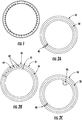
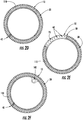
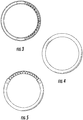
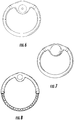
- a first embodiment of the invention relates to an intravaginal device comprising: a first segment comprising:
- a second embodiment of the invention relates to the above intravaginal device for use in relieving vaginal dryness from vaginitis, inflammation of the vagina, and of the outer urinary tract, due to the thinning and shrinking of the tissues, sexual arousal disorder, menopause, drug-induced vaginal dryness, dyspareunia, sexual pain disorder, pregnancy, hormone imbalance, anxiety or diabetes.
- references in the description to methods of treatment refer to the compounds, pharmaceutical compositions and medicaments of the present invention for use in a method of treatment of the human or animal body by therapy.
- the present technology provides devices and their use for intravaginal delivery of aqueous lubricants.
- Lubricants of the present technology include only those lubricants that are suitable for use on vaginal tissues.
- aqueous lubricant is meant water or any water-based solution, emulsion, suspension, gel or foam that can provide lubrication and moisture to the vaginal tissues.
- use of intravaginal devices of the present technology directly relieve the symptoms of vaginal atrophy, dryness, irritation, pain and discomfort.
- the aqueous lubricants released by the present devices can soothe and revitalize or restore dry tissues within the vaginal mucosa.
- the lubricants may also be formulated to maintain appropriate pH and physiology and promote a normal vaginal environment.
- the present devices are non-irritating, safe, easy to use, and typically, hormone free. They may be designed for use over several hours, a single day or continuously for up to 30 days.
- the present technology provides intravaginal devices that include a first segment that includes an outer surface and a lumen containing an aqueous lubricant, e.g., a moisturizing or wetting agent.
- the first segment is configured to deliver the contents of the lumen to the outer surface by diffusion, for example, in a controlled or sustained fashion.
- the first segment includes a hydrophilic, semi-permeable elastomer that is water-swellable and is selected from the group consisting of hydrophilic polyurethane, hydrophilic silicone polyurethane copolymer, and hydrophilic polyether polyamide, wherein no macroscopic channels are present in the first segment.
- the devices may be an intravaginal ring, a tampon-shaped device, or any other size and shape suitable for residence in a subject's vagina.
- lubricant delivered to the outer surface of the device will be available for lubrication of vaginal tissues.
- the elastomer is not gelatin and does not dissolve in the vaginal environment.
- the first segment of the intravaginal device includes a hydrophilic, semi-permeable elastomer. Because such polymers are semi-permeable, they allow the aqueous lubricant to slowly diffuse from the lumen to the outer surface of the device. No macroscopic channels such as slits or holes are present in the first segment. Such are not necessary to deliver the aqueous lubricant in devices due to the use of such polymers to form the lumen and outer surface of the device.
- the hydrophilic elastomers are water-swellable; e.g., in water they may swell up to 500% of their dry weight.
- the hydrophilic elastomer of the device swells from about 20 wt% to about 500 wt% over its dry weight. In other embodiments the hydrophilic elastomer swells from about 5 wt%, about 10 wt%, about 20 wt%, about 30 wt%, about 40 wt%, or about 50 wt% up to about 100 wt %, about 150 wt%, about 200 wt%, about 300 wt%, about 400 wt% or about 500 wt% over its dry weight or over a range including any two such values.
- hydrophilic, semi-permeable elastomers for use in the present devices are selected from the group consisting of hydrophilic polyurethane, hydrophilic silicone polyurethane copolymer, and hydrophilic polyether polyamide.
- Hydrophilic polyurethanes are a class of thermoplastic or thermoset elastomers that may contain a mixture of soft blocks in the urethane that are both hydrophilic and hydrophobic. (See, e.g., Y. Gnanou, G. Hild, P. Rempp, "Hydrophilic polyurethane networks based on poly(ethylene oxide): synthesis, characterization, and properties.
- the hydrophilic soft block may be made from polyethylene oxide and the hydrophobic soft block may be polytetramethylene oxide.
- These soft blocks can be mixed at certain ratios known in the art to allow the polyurethane to absorb water and therefore allow water and molecules to pass across the polyurethane. Even though the polyurethane is impregnated with water, the polyurethane retains its elastomeric properties and can still function as a comfortable biomedical device.
- the polyurethane is made from only a hydrophobic soft block such as polytetramethylene oxide, the resulting polymer is almost impermeable to water and would not be useful in the delivery of water slowly to vaginal cavity.
- aliphatic diisocyanates form the urethane linkages between the block copolymers because aliphatic diisocyanates do not degrade into toxic aromatic diamines.
- Hydrophilic polyurethanes include polyurethanes having ionomeric groups in the backbone of the polyurethane such as, but not limited to, carboxylic acids.
- ionomeric groups in the backbone of the polyurethane
- Other ionomeric and water soluble functional groups such as urea will allow water to be imbibed into the elastomer and will allow the elastomer to swell.
- FE Gould "Hydrophilic polyurethanes of improved strength" US Patent No.
- hydrophilic polyurethanes are TECOPHILIC (a hydrophilic copolymer urethane containing both polyethylene oxide and polytetramethylene oxide soft blocks available from Lubrizol Advanced Materials, Inc., Cleveland, OH), HYDROTHANE (an aliphatic polyether polyurethane, available from AdvanSource Biomaterials Corp., Wilmington, MA), a hydrophilic styrene ethylene butylene styrene block copolymer or hydrophilic styrene butadiene styrene block copolymer DRYFLEX (Elasto, Sweden), and polyether urethanes such as HYDROMED 640 (AdvanSource Biomaterials Corp., Wilmington, MA).
- TECOPHILIC a hydrophilic copolymer urethane containing both polyethylene oxide and polytetramethylene oxide soft blocks available from Lubrizol Advanced Materials, Inc., Cleveland, OH
- HYDROTHANE an aliphatic polyether
- hydrophilic polyurethanes may further include alkyl groups, polyethylene glycol groups, fluoroalkyl groups, charged groups (e.g., carboxylic acids, amines and the like) or other chemical groups attached to the reactive isocyanates attached to the ends of the polymer chains during synthesis ( US Patent 5,589,563 ).
- Hydrophilic silicone polyurethane copolymers are polymers that are a mixture of polyether segments and polydimethylsiloxane rubber (PDMS) segments copolymerized in linear block copolymers that can be melt processed.
- PDMS polydimethylsiloxane rubber
- this class of polymers there will need to be added a hydrophilic group like polyethylene oxide or segments that contain ionomeric groups so that the normally hydrophobic nature of PDMS can be counteracted so the polymer can imbibe water and deliver it through the device membrane ( US Pat. 5,756,632 ).
- Preferred embodiments use aliphatic diisocyanates to form the block copolymers.
- Hydrophilic polyether polyamides include PEBAX (Arkema, Inc., France) and polyether block amide copolymers.
- Polyether block amide copolymers i.e. polyamidepolyether copolymers (PAEPC) are described in U.S. Pat. No. 4,361,680 (1982) to Borg et al ; U.S. Pat. No. 4,332,920 (1982) to Foy et al ; and U.S. Pat. No. 4,331,786 (1982) to Foy et al.
- PAEPC polyamidepolyether copolymers
- These polymers can be modified with enough hydrophilic groups like polyethylene oxide to increase their hydrophilicity and allow them to absorb water so it can be delivered through the device membrane or wall.
- IVDs of the present technology may be manufactured using opacifiers, colors, fragrances and the like to tailor the appearance and smell of the IVDs as desired.
- the lubricant delivered by the first segment of the intravaginal devices of the invention is aqueous.
- the aqueous lubricant can be water, hypo-osmolar water or solution, an aqueous solution, hyper-osmotic water or solution, iso-osmotic water or solution, and aqueous solution, or a gel.
- the aqueous lubricant may be at least 90 wt% water or at least 95 wt%, at least 96 wt%, at least 97 wt%, at least 98 wt% or at least 99 wt% water, or essentially 100 wt% water.
- the aqueous lubricant is iso-osmolar or hypo-osmolar and may include ions such as potassium, sodium, chloride and phosphate, e.g., at about 0.1 wt% to about 0.25 wt%, about 0.5 wt% or about 0.75 wt%.
- the aqueous lubricant may be buffered, optionally at an acidic pH to promote the natural acidity of the vagina.
- the present aqueous lubricants may have a pH of about 3 to about 8, from about 3 to about 6 or from about 3.5 to about 4.5 or about 4.
- the aqueous lubricant may include vaginal fluid simulant, about 5 to about 50 mM lactic acid, an acetic acid buffer at a pH of about 3.5 to about 4.5 or to about 5.0, and optionally about 5 to about 50 mM glucose.
- the aqueous lubricant may include vaginal fluid simulant, about 20 to about 30 mM (or about 25 mM) lactic acid, a 10 mM to about 30 mM (or about 18 mM) acetic acid buffer at a pH of about 3.5 to about 4.5 or to about 5.0 and optionally about 20 to about 30 mM (or about 25 mM) glucose.
- the aqueous lubricant may be free of steroids or may be free of any active pharmaceutical ingredient (i.e., those ingredients that have a therapeutic effect as opposed to a non-therapeutic biological effect).
- the present aqueous lubricants may include water and a wide variety of additives such as, but not limited to, one or more salts, nonaqueous solvents (e.g., propylene glycol, glycerol), acids such as C1-8 carboxylic acids (i.e., carboxylic acids having 1-8 carbons such as, e.g., lactic acid, acetic acid), glucose, antioxidants (e.g., BHT, ascorbic acid), preservatives (e.g. sorbital, sorbic acid, parabens, EDTA, sodium benzoate, tocopherol), surfactants (e.g.
- nonaqueous solvents e.g., propylene glycol, glycerol
- acids such as C1-8 carboxylic acids (i.e., carboxylic acids having 1-8 carbons such as, e.g., lactic acid, acetic acid), glucose, antioxidants (e.g., BHT, ascorbic acid), pre
- the lubricants may include pyridine, squalene, urea, complex alcohols, aldehydes, ketones, stearic acid, stearate, isopropyl palmitate, petrolatum, aloe barbadensis (Aloe Vera) leaf juice, cucumus sativus extract, helianthus annulus seed oil, soybean sterol, vitamin E acetate, vitamin A palmitate, provitamin B5, sodium acrylate/acryloyldimethyl taurate copolymer, dimethicone, glyceryl stearate, ceylalcohol, lecithin, mineral water, sodium PCA, potassium lactate, collagen, aminoacids, triethanolamine, DMDM, hydantoin, iodopropynyl, butylcarbamate, diso
- the additives may be added at a concentration such that the aqueous lubricant is hypo-osmotic, hyper-osmotic or iso-osmolar in comparison to vaginal fluids or blood or tissue.
- hypo-osmotic lubricant is meant that the osmolality of the lubricant is less than that of the vaginal fluid, or blood, or tissue fluid.
- a hyper-osmotic lubricant has an osmolality that is greater than that of the vaginal fluid, or blood, or tissue fluid, while an iso-osmotic lubricant roughly matches the osmolality of the vaginal fluid, or blood, or tissue fluid.
- Hyper-osmotic lubricants may be aqueous or non-aqueous. Such non-aqueous lubricants may be water-soluble ( i.e., at least 1 mg/mL at 25°C). Hyper-osmotic lubricants may be prepared from appropriate concentrations of various agents including, but not limited to, glycerol, polyethylene glycol, propylene glycol, carrageenan (i.e., sulfated polysaccharides), other lubricating or hydrating substances, salts, and hyper-osmotic aqueous agents, and the like.
- Hyper-osmotic lubricants may include, e.g., 100% glycerol or mixtures of water and glycerol such as at least 4 wt%, about 4 wt%, about 10 wt%, about 20 wt%, about 30 wt%, about 40 wt%, about 50 wt%, about 60 wt%, about 70 wt%, about 80 wt%, about 90 wt%, about 91 wt%, about 92 wt%, about 93 wt%, about 94 wt%, about 95 wt%, about 96 wt%, about 97 wt%, about 98 wt%, about 99 wt% glycerol, or ranges between and including any two such values.
- Hyper-osmotic lubricants may also include, e.g., 100% propylene glycol or mixtures of water and propylene glycol such as about 3 wt%, about 10 wt%, about 20 wt%, about 30 wt%, about 40 wt%, about 50 wt%, about 60 wt%, about 70 wt%, about 80 wt%, about 90 wt%, about 91 wt%, about 92 wt%, about 93 wt%, about 94 wt%, about 95 wt%, about 96 wt%, about 97 wt%, about 98 wt%, about 99 wt% propylene glycol, or ranges between and including any two such values.
- the aqueous lubricant in the lumen of the first segment may be an hyper-osmotic solution comprising glycerol.
- the lubricant from an IVD placed in the vagina and filled with glycerol or other appropriate hyper-osmotic agent diffuses down its concentration gradient from the IVD and into the vaginal space. Because there are potentially two or more diffusing species (e.g., the osmotic agent in the device and the physiologic fluid outside the device), co-diffusion of both of these agents can occur leading to behavior that varies with time.
- the hyper osmotic device also attracts water from the vagina due to the low concentration of water in the device and thus a water concentration gradient is present in the system.
- the hydrophilic elastomer of the IVD swells with water and releases glycerol, while still attracting water into the device.
- glycerol Once the glycerol is present in the vaginal lumen at a concentration that is hyper-osmotic to blood, water diffuses from the bloodstream and hydrates the vaginal cavity along with the moisturizing effect of the glycerol.
- An additional benefit may be that the water absorbed into the polymer that was initially attracted by the glycerol (or other hyper-osmotic agent) later may act as a hydration source that could be released in response to the moisture needs of the vaginal mucosa at a later time when all of the hypo-osmotic agent has diffused from the IVD.
- the lubricant when it is an aqueous gel, it may include, e.g., water and one or more additives selected from the group consisting of preservatives or disinfectants (e.g., benzalkonium chloride, benzethonium chloride, benzoic acid, benzyl alcohol, boric acid, calcium lactate, glycerin, glacial acetic acid, hibitane acetate, methyl paraben, phenylethyl alcohol, potassium sorbate, propylene glycol, propyl paraben, sodium benzoate, sodium ethyl paraben, sodium propionate, sorbic acid, sorbital, tocopherol), thickening/gelling agents (e.g., agarose, aluminum magnesium silicate, carbomer, carbopol, carrageenans, dermatan sulfate, ethyl cellulose, silicon dioxide, guar gum, hydroxyethyl cellulose, hydroxyethyl meth
- the aqueous gel lubricant may also be a water emulsion.
- the gel may be also in a dry form that is mounted on the ring and is hydrated in the vagina by the aqueous solution lubricant.
- the dry gel may contain a probiotic.
- Probiotics are live microorganisms thought to be healthy for the host organism. According to the currently adopted definition by FAO/WHO, probiotics are: "Live microorganisms, which when administered in adequate amounts confer a health benefit on the host for example Lactic acid bacteria (LAB) or Lactobacillus.”
- the amount of aqueous lubricant that may be released by the present devices may vary.
- the present intravaginal devices may deliver 0.001 mg to about 1000 mg or even up to 2000 mg of lubricant to the outer surface of the device per day.
- the amount of lubricant delivered may be at least about 0.01 mg, about 0.1 mg, about 1 mg, about 5 mg, about 10 mg, about 25 mg, about 50 mg, about 75 mg, about 100 mg, about 250 mg, about 500 mg, about 750 mg, about 1000 mg, or about 2000 mg per day or a range between or including any two of the foregoing values.
- the rate of lubricant delivered will depend on the amount of dryness or water content of the vaginal epithelium. If the vagina is wet, less lubricant will be released, and if it is dry, more will be released. This means that the amount of lubricant that is released will change over time after the initial release from the device. Functionally this is an on demand release rate based on the water content of the vaginal epithelium.
- Intravaginal devices of the present technology may have a first segment that includes a tube formed from the polymer and having two ends. The ends of the first segment may be joined to each other to form, e.g., an intravaginal ring.
- the intravaginal devices may further include one or more additional segments, each of which comprises a polymer, an outer surface and optionally a lumen.
- the additional segments may contain different lubricants or other substances for delivery to the vagina.
- a segment may contain an aqueous gel lubricant and another segment may contain an aqueous solution lubricant.
- Each additional segment may be separated from any adjacent segment by a polymer segment or plug.
- the polymer segment or plug may be a hydrophobic polyurethane such as TECOFLEX or ethylene vinyl acetate.
- the polymer of the first segment is different from the polymer of at least one additional segment.
- the at least one additional segment may be a hydrophobic elastomer.
- the device may include one solid segment and one segment with a lumen.
- the segment including the lumen includes an aqueous gel lubricant.
- the intravaginal device is refillable with aqueous lubricant.
- the intravaginal devices of the present technology may be designed to include one or more release chambers ("pods") for the release of additional lubricant(s) or other substances, including but not limited to drugs, as described in USSN 61/375,671, filed 8/20/2010 and entitled "Devices and methods for intravaginal delivery of drugs and other substances.”
- the intravaginal device further includes one or more pods loaded with an agent selected from the group consisting of drugs and probiotics such as, e.g., Lactobacillus, vitamins, and minerals.
- the pods may be located on the inner side of the ring or the outer side of the ring (See, e.g., FIGS. 2C , 2F , 6, 8 ).
- the intravaginal device is an intravaginal ring having a pillow ring on the inner side of the ring.
- the pod contains an ovule (see, e.g., FIG 7 ).
- the ovule is a lumen containing a non-aqueous solution lubricant surrounded by a gelatin coating that dissolves when placed in the vagina.
- Such ovules are available as K-Y® Brand LIQUIBEADS (Johnson & Johnson Healthcare Products Division of McNeil-PPC, Inc., Skillman, NJ).
- the intravaginal devices of the present technology include a wide variety of designs.
- the device may be an intravaginal ring.
- Such rings may have an outer diameter ranging from about 40 mm to about 80 mm (e.g., from about 50 mm to about 70 mm, or about 60 mm).
- the ring may further have a cross-sectional diameter ranging from about 3 mm, from about 5 mm, or from about 7 mm to about 10 mm or to about 12 mm, and/or an inner diameter of about 1 mm, about 2 mm, about 3 mm, about 4 mm, or about 5 mm to about 6 mm, to about 8 mm, to about 10 mm, or to about 11 mm (e.g., 8 mm).
- the walls of the ring may range in thickness from about 0.3 mm to about 3 mm (e.g., about 0.5 to about 1 or about 2 mm).
- the rings may be circular, oval, tear-drop shaped, hour-glass shaped or any other suitable shape for use in the vagina.
- the ring or device may have accordion-like folds that allow for extra capacity in the lumen, but sufficient structural integrity to maintain its basic shape when filled with aqueous lubricant.
- the intravaginal rings and devices of the present technology are flexible and may be constructed so that a force of not more than 10N is sufficient to compress the ring or device by 10%, or in some embodiments, 25%.
- the ring further comprises a spring configured to support the ring or any part thereof. The spring may be embedded in or inserted into the ring and encircles at least one lumen of the ring.
- vaginal atrophy The most common cause of vaginal atrophy is the decrease in estrogen, which happens naturally during perimenopause, and increasingly so in post-menopause. However this condition can sometimes be caused by other circumstances and can occur throughout a woman's lifetime.
- the symptoms can include vaginal soreness and itching, as well as painful intercourse, and bleeding after sexual intercourse. The shrinkage of the tissues can be extreme enough to make intercourse impossible.
- the cause of vaginal atrophy is usually the normal decrease in estrogen as a result of menopause.
- the present technology provides the intravaginal device disclosed herein for use in relieving vaginal dryness from vaginitis, inflammation of the vagina, and of the outer urinary tract, due to the thinning and shrinking of the tissues, sexual arousal disorder, menopause, drug-induced vaginal dryness, dyspareunia, sexual pain disorder, pregnancy, hormone imbalance, anxiety or diabetes.
- the device may deliver any of the aqueous lubricants described herein, including water, aqueous solution, hypo-osmolar water, iso-osmolar or hyper-osmotic solution.
- the aqueous lubricant may be delivered to the vaginal tissue in the form of a liquid, a vapor or a combination of both.
- the device delivers 0.001 - 1000 mg or even up to 2000 mg of lubricant to the outer surface of the device per day.
- Other amounts of lubricant may be delivered as described herein.
- the lubricant may be delivered over any period of time ranging from 1 hour to 1 month. Thus, the period that the lubricant is delivered may range from 1, 2, 3, 4, 5, 10, 18, or 24 hours, or may range from 1, 2, 3, 4, 5, 6, 7, 8, 9, 10, 11, 12, 13, 14, 15, 16, 17, 18, 19, 20, 21, 22, 23, 24, 25, 26, 27, 28 , 29, 30 or 31 days.
- the present technology in another aspect provides methods of making the intravaginal devices as described herein.
- the intravaginal devices are an intravaginal ring
- the extrusion molding is joined together by welding.
- the material is then swollen or loaded with lubricant into its final ring shape.
- the methods include adding a physiologically acceptable water-soluble ionic or non-ionic material to a lumen of an intravaginal device and exposing (e.g., soaking) the intravaginal device to water.
- the ionic material may include an alkali halide salt (e.g., NaCl, KCl) and/or other salts including but not limited to sodium acetate, potassium acetate, sodium phosphate, sodium hydrogen phosphate.
- the non-ionic material may include but is not limited to glycerol, polyethylene glycol, or propylene glycol.
- Hyper-osmotic devices will be able to attract water or aqueous lubricant into the ring internal lumen without puncturing the lumen.
- the time this may take is between 1 and 24 hours depending on permeability of the membrane and the amount and nature of the osmotic attractant.
- Comparative Example 1 Single Segment Tubular IVR Constructed of Hydrophobic Elastomeric Tubing with Multiple Holes Containing Aqueous Gel Lubricant.
- a length of 6.5 mm outer diameter hydrophobic TYGON tubing (Saint-Gobain Corp., Paris, France) with a 1 mm wall thickness was formed into a ring of diameter of ⁇ 55-60 mm, by connecting the ends of the tubing with a hollow plug comprised of the same tubing material.
- the hollow plug dimensions were chosen as to connect the tubing ends to form a full ring structure. Small holes were drilled into the tubing along the outer annulus of the ring at ⁇ 1 cm spacings. Aqueous lubricant was loaded into the lumen via a syringe needle.
- Comparative Example 2 Single Segment Tubular IVR Constructed of Hydrophobic Elastomeric Tubing with Multiple Slits Containing Aqueous Lubricant.
- a ring of similar dimensions and construction as described in Example 1 was formed, however slits rather than holes were spaced along the inner annulus of the ring, parallel to the central ring axis.
- Lubricating gel JUICY LUBE, ID LUBRICANTS, Westridge Laboratories, Inc., Santa Ana, CA
- Application of external force to the ring results in the expulsion of the lubricating gel from the lumen through the slits to the outer surface of the inner annulus of the tubular IVR.
- the slits are in compression and thus closed unless a force (such as that which may arise from the contraction and relaxation of vaginal musculature) is applied to the IVR.
- a force such as that which may arise from the contraction and relaxation of vaginal musculature
- Example 3 Single Segment Tubular IVR Constructed of Hydrophilic, Semi-Permeable Elastomeric Tubing Containing Water.
- TECOPHILIC HP-93A-100 is made of a hydrophilic, semi-permeable elastomeric polyurethane that swells to 100% of its weight when placed in water.
- a length of this tubing was submersed in water and the two ends of the tubing were connected to each other using a connector made from polyethylene tubing that has an outer diameter that is slightly larger than the inner diameter of the TECOPHILIC tubing while still submersed in water to form a ring. When removed from the water, the water-swelled ring contained approximately 5 mL of water within the lumen.
- the water-swelled ring had an outer diameter of ⁇ 60 mm with a tubing outer diameter of ⁇ 8 mm.
- the wall thickness of the water-swelled tubing was estimated to be ⁇ 2 mm.
- Excess water from the surface of the ring was removed.
- a line drawing of the ring is shown in FIG. 3 .
- the surface of the ring continued to remain moist as a result of permeation of the water from the lumen through the polyurethane to the outer surface of the ring.
- a moisturizing and hydrating effect was noted. Over several days, air bubbles became visible in the lumen as a result of pressure equalization due to the continued water migration from the lumen, through the microporous holes of the polyurethane tubing and subsequent evaporation from the outer surface of the ring.
- Example 4 Two Segment Tubular IVR Constructed of a Hydrophilic, Semi-Permeable Elastomeric Segment Containing Water and a Hydrophobic Elastomeric Segment with Multiple Holes Containing a Gel Lubricant.
- a first length of a hydrophobic tubing made out of TYGON, approximately 50 mm long with an outer diameter of 7 mm was plugged at each end using a small plug of molten polyurethane. Such plugs were employed to prevent/ mixing of the contents upon connecting the first segment to the second segment.
- a second segment was created by taking a second length of tubing made of TECOPHILIC HP-93A-100, a hydrophilic, semi-permeable polyurethane elastomer. The ends of the first segment were connected to the ends of the second segment using appropriately sized hollow polypropylene tubing connectors to form a ring. Two holes, approximately 1 mm in diameter were placed parallel to the ring axis in the first segment.
- the first segment was filled with gel lubricant using a syringe.
- the second segment was filled with water, also using a syringe.
- the two segment tubular IVR thus constructed released both a small amount of vaginal lubricant as well as aqueous lubricant over a period of time.
- Example 5 Two Segment Tubular IVR Constructed of a Hydrophilic, Semi-Permeable Elastomeric Segment Containing Water and a Hydrophobic Elastomeric Segment with Multiple Holes Containing Vaginal Lubricant.
- Example 4 As a variation to Example 4, two holes, approximately 1 mm in diameter were drilled perpendicular, rather than parallel, to the ring axis. A similar effect was achieved as in Example 4.
- Example 6 Collapsible Hydrophobic Tubing.
- the IVR in Example 5 may be modified by employing hydrophobic tubing, which has small holes and is collapsible under vaginal pressure. Such pressure provides the force necessary to expel the vaginal lubricant from the lumen through the holes and to the outer surface the tubular IVR.
- Comparative Example 7 Collapsible Hydrophobic Tubing with a Support Band.
- the IVR in Comparative Example 1 may be modified by incorporation of a band of flexible spring material (e.g., nylon or spring steel) into the ring, providing support to the ring as well as a retractive force useful for retention of the ring in the vaginal canal.
- a band of flexible spring material e.g., nylon or spring steel
- Example 8 Membrane-containing IVRs, structurally supported.
- the water-swellable tubing is made thin, at a wall thickness of, but not limited to, 0.1 mm to 3 mm to allow for delivery of the aqueous solution lubricant.
- This thin structure may not be strong enough to provide a counterbalancing force to keep the ring in the vaginal canal. Therefore, the water-swellable tubing can be stiffened using a number of support-structures that are well known in the art.
- the water-swellable tubing is extruded at a cross sectional diameter of, but not limited to, 2 mm to 10 mm and is wrapped with fiber mesh support-structure and then jacketed with another layer of molten water-swellable tubing.
- the water-swellable tubing of cross sectional diameter of, but not limited to, 2 mm to 10 mm is jacketed over a spring or a metal mesh support-structure that is made of materials including but not limited to titanium, KEVLAR, nylon, carbon fiber, stainless steel or other spring like materials or polymers that can be jacketed in a jacketing mold tool.
- the resulting water-swellable tubing when formed into ring would have a force to compress the IVR 10% of its initial outer diameter of, but not limited to, approximately 0.25 to 10 N.
- the resulting tube is cut into the correct length of, but not limited to, approximately 10 to 30 cm and formed into a ring by directly welding the water-swellable tubing ends together.
- a connector is used to form rings from the length of water-swellable tubing.
- the connector is a part that either jackets the water-swellable tubing or is inserted into the water-swellable tubing.
- the connector is welded into the water-swellable tubing making an intact and aqueous solution lubricant tight device where the aqueous solution lubricant is not leaking through the connection of the two ends of the water-swellable tubing.
- the weld is made by solvent welding, heat welding, induction welding, butt welding, or other thermoplastic welding techniques well known to those skilled in the art.
- the device is dry at this point and is filled with the aqueous solution lubricant.
- the aqueous solution lubricant is filled into the device at a volume of, but not limited to, 1 to 12 mL, via a syringe or similar filling apparatus that enters the device through a port built into the connector that reseals after the syringe is removed.
- the aqueous solution lubricant filling port is mounted in the water-swellable tubing.
- the device with a thin wall would collapse due to the reduced amount of aqueous solution lubricant in the core of the device after being placed in the vagina.
- This problem is alleviated by adding a support-structure to the water-swellable elastomer of the device.
- a check valve that allows gasses into the device, but does not allow appreciable water out of the ring through the check valve, is formed into the device.
- the check valve is assembled into the connector that connects the two ends of water-swellable tubing together in a torus shape (i.e., an IVR).
- the check valve is mounted into the water-swellable tubing.
- a piece of gas permeable membrane e.g., GORE-TEX is mounted in the connecter and allows air into the device after aqueous solution lubricant is released.
- the gas permeable membrane is mounted on a hole that is formed in the water-swellable tubing.
- Example 10 Rigidification of Hydrophilic Tubing.
- the water-swellable tubing is thin, at a wall thickness of, but not limited to, 0.1 mm to 3 mm to allow for delivery of the aqueous solution lubricant.
- This thin structure may not be strong enough to provide a counterbalancing force to keep the device in the vaginal canal. Therefore, the water-swellable tubing can be stiffened using a number of support-structures that are well known in the art.
- the water-swellable tubing is extruded at diameter of, but not limited to, 2 mm to 10 mm and wrapped with fiber mesh support-structure and then jacketed with another layer of molten water-swellable tubing.
- the water-swellable tubing is jacketed over a spring or a metal mesh support-structure that is made materials, including but not limited to, titanium, KEVLAR, nylon, carbon fiber, stainless steel or other spring like materials or polymers that can be jacketed in a jacketing mold.
- the resulting water-swellable tubing when formed into ring would have a force to compress the IVR 10% of its initial outer diameter of, but not limited to, 0.25 to 10 N.
- the resulting tube is cut into the correct length of, but not limited to, approximately 10 to 30 cm and formed into a ring by directly welding the water-swellable tubing ends together.
- the lumen of the device of this example is filled with water.
- a gel forming formulation is attached to or inserted in the ring.
- the gel forming formulation includes polymers such as, but not limited to, hydroxyethyl cellulose, carrageenans, dermatan sulfate, hydroxypropyl cellulose, polyethylene oxide, methyl cellulose.
- the gel forming formulation may also include lanolin, aloe vera, moisturizers, preservatives, vitamins and probiotics or other agents known to those skilled in the art.
- One aspect uses a connector that is attached on the end of the water-swellable tubing and is used to form a torus from the length of water-swellable tubing.
- the connector is a part that either jackets the water-swellable tubing or is inserted into the water-swellable tubing.
- the connector has attached to it the ability to hold a compressed pellet of gel forming formulation.
- the connector is welded into the water-swellable tubing making an intact and aqueous solution lubricant tight device where the aqueous solution lubricant is not leaking through the connection of the two ends of the water-swellable tubing.
- the weld is made by solvent welding, heat welding, induction welding, butt welding, or other thermoplastic welding techniques well known to those skilled in the art.
- the device is dry at this point and is filled with the aqueous solution lubricant.
- An IVR was constructed containing two separate reservoirs.
- One reservoir was made from a hydrophilic polymer and the other from a hydrophobic polymer with pores in the elastomer. These separate reservoirs can be used to hold and release different liquids/lubricants.
- the first segment (hydrophilic polymer) delivered the aqueous solution lubricant and the second segment (hydrophobic polymer) delivered the aqueous gel lubricant.
- the aqueous gel lubricant is delivered through pores in the tubing wall.
- the device was fabricated from an 80 mm length of TECOFLEX EG-85A tubing segment (5.5 mm cross-section x 1.5 mm wall thickness) and an 80 mm length of hydrophilic aliphatic thermoplastic polyurethane tubing segment (5.5 mm cross-section x 0.7 mm wall thickness).
- the ends of the TECOFLEX segment were sealed using a PlasticWeld Systems, Inc. (Newfane, NY) bonding die (HPS-EM; preheat 10 seconds, heat 11 seconds, cool 15 seconds, power 16%, travel distance of 3 mm). After sealing the ends, a 0.5 mm drill bit was used to drill holes along one side of the sealed tube, approximately every 3 mm starting and ending 20 mm from each end to give 20 holes.
- holes were only drilled into one wall of the tube, forming a channel from the inner lumen to the surface of the tube.
- the holes can be drilled all around the rod axially so that the holes point in many directions.
- this design can be configured as a tampon-like device.
- the ends of the hydrophilic aliphatic thermoplastic polyurethane segment were sealed using a bonding die (HPS-EM). By placing the clamp 9 mm from the die opening, a 6 second preheat cycle was followed by a 7 second heat cycle with a 10 second cooling cycle following. The ends of each segment were joined together using an induction welder split die (HPS-20).
- the ends were placed into the die, clamped, and subjected to a 25 second cycle at 50% power followed by a 12 second soak and a 20 second cooling cycle, resulting in the joining of the ends and then repeated to form the ring.
- the pores in the TECOFLEX segment were configured to place the drilled holes along the inner annulus of the IVR.
- the IVRs were annealed at 65°C for 5 minutes and cooled at 10°C for 20 minutes.
- a 0.360 mm (27 gauge) needle was inserted along the inner annulus of the IVR through the joint and into the lumen of the TECOPHILIC side.
- Another needle was inserted into the lumen on the other side of the joint and a 3 mL syringe was used to inject 0.5 grams of water into the IVR until the liquid started to emerge out of the other needle, thus filling the TECOPHILIC side of the IVR device.
- a 0.360 mm (27 gauge) needle and 3 mL syringe was used to inject the lumen of the TECOFLEX side with 0.1 grams of a 0.2 wt% methylene blue/K-Y® Brand Jelly (Johnson & Johnson Healthcare Products Division of McNeil-PPC, Inc., Skillman, NJ) mixture.
- the devices described above can be made via a multistep injection molding process where the water swellable tubing is formed into the device by methods well known to those skilled in the art.
- Example 12 IVRs of varying shapes.
- any of the IVRs of the present technology can be modified as to promote increased comfort and/or to promote increased contact with the vaginal canal.
- the IVR may be deformed or changed from a toroid shape.
- any of the examples listed are readily adaptable to cylindrical shape such as that of a tampon (see Examples 40-41 below).
- the IVR is shaped similar to an "accordion" or “bellowed” to increase the surface area of the tubing that is in contact with the vaginal epithelium.
- the shape of the IVR is elliptical, which increases comfort for the patient.
- the pods or cores are located on the outer portion of the IVR, rather than on the inner portion of the IVR.
- the concept of the pods or cores on the IVR are the addition of one or two or more pods or cores attached to or inserted into the IVR.
- the pods or cores deliver substances such as carrageenans simultaneously with the aqueous solution lubricant.
- the ring is bent out of plane to be curved, which may increase comfort to the patient and increase the surface area in contact with the vaginal epithelium.
- the ring is the shape of an "hour-glass,” which also increases the comfort to the patient.
- the IVR is prepared in the shape of a circle, with adjoining "pillows" on four sides of the inner portion of the ring containing a greater quantity of aqueous solution lubricant.
- the dimensions of the ring are approximately 60 mm in total diameter.
- the outer portion of the ring containing the aqueous solution lubricant is 3 to 10 mm in diameter, and the diameter is approximately 7 mm of swollen polymer tubing.
- Adjoining pillows attached to four sides of the inner tubing are up 10 to 25 mm inward from the outer edge of the tubing. This would leave up to 10 mm of hollow space in the center of the "pillowed" IVR for fluid lubricant.
- Example 13 Method of Insertion.
- the device is inserted into the vagina using a device or ring applicator ( WO/1999/038468 and US Patent No. D442,688 ) or feminine product applicators similar to those supplied with tampons and lubricant or moisturizer products.
- a device or ring applicator WO/1999/038468 and US Patent No. D442,688
- feminine product applicators similar to those supplied with tampons and lubricant or moisturizer products.
- Example 14 Acidifying Agents in the IVR.
- IVR includes pH modifying agents (e.g ., adipic acid, alkyl fumarate, aluminium sulfate, calcium acetate, calcium carbonate, calcium lactate, citric acid, glacial acetic acid, glutamic acid, glycine, hydrochloric acid, lactic acid, methionine, phosphoric acid, potassium bitartarate, sodium dihydrogen citrate, sodium citrate, sodium dibasic phosphate, sodium carbonate, sodium bicarbonate, sodium hydroxide, sodium lactate, sodium monobasic phosphate, succinic acid, tartaric acid) in the aqueous lubricant to promote the natural acidity of the vagina.
- pH modifying agents e.g ., adipic acid, alkyl fumarate, aluminium sulfate, calcium acetate, calcium carbonate, calcium lactate, citric acid, glacial acetic acid, glutamic acid, glycine, hydrochloric acid, lactic acid, methionine,
- Example 15 Continuous Release of Aqueous Lubricant.
- An IVD of the present technology is administered to a woman in need of or desiring and a sufficient amount of the aqueous and optionally non-aqueous lubricant (including, e.g., gel lubricant) is released continuously over 24 to 72 hours or up to including 5 to 7 days or up to 30 days to provide relief from vaginal dryness or vaginal discomfort.
- a sufficient amount of the aqueous lubricant (and gel lubricant) is released continuously over several minutes to several hours (up to 24 hours) to provide relief of vaginal dryness or vaginal discomfort.
- a sufficient amount of the aqueous lubricant and gel lubricant is released continuously over several days (3 to 7 days) to provide relief of vaginal dryness or vaginal discomfort.
- the aqueous solution lubricant and gel lubricant is released in such a manner that it would provide sufficient relief of vaginal dryness or vaginal discomfort and be used as needed on an as needed basis from several minutes to several days.
- the IVD remains in place from several minutes to several days and is removed when the woman determines she has sufficient relief, or wears for as long as desired for up to several days.
- Comparative Example 16 Solid Polymer Matrix IVR Constructed of TECOPHILIC SP-80A- 150
- a matrix IVR was constructed that is capable of holding various fluids using water-swellable polymers that can hydrate (swell) up to but not limited to 150% of its dry mass, such as with TECOPHILIC SP-80A-150.
- Rods of TECOPHILIC SP-80A-150 were cut to 110 mm and the ends were joined by induction welding using a split die welder (HPS-20) settings of 45% power for 25 seconds followed by an 18 second soak and 20 second cool. After the joint was completed, it was allowed to cool for 10 minutes on the inside of a small beaker to support the cooling joint.
- the rings were annealed to make the device circular by: 1) securing the rings around the cylindrical neck of a 125 mL Erlenmeyer flask and heating in a convection oven at 80°C for 5 minutes, then air cooled at room temperature for 10 minutes.
- a matrix IVR loaded with iso-osmolar fluid was prepared as follows.
- TECOPHILIC SP-80A-150 intravaginal rings (IVRs) were placed in 100 mL of 100 mM acetate buffer, containing 30 mM NaCl (pH 5, 305 mOsm) for 4 days to swell the polymer to equilibrium.
- a matrix IVR loaded with a hypo-osmolar fluid was prepared as follows. TECOPHILIC SP-80A-150 IVRs were placed in 100 mL of distilled de-ionized (DDI) water for 4 days to swell the polymer to equilibrium.
- DAI distilled de-ionized
- a matrix IVR loaded with a hyper-osmolar fluid was prepared.
- TECOPHILIC SP-80A-150 IVRs were placed in 100 mL of a 70/30 %v/v mixture of 100 mM acetate buffer with 30 mM NaCl and 3.8 M glycerol (pH 5, 428 mOsm) for 4 days to swell the polymer to equilibrium.
- glycerol could be replaced with propylene glycol.
- a matrix IVR loaded with vaginal fluid simulant (VFS) was prepared as follows. To prepare 1 L of VFS, the following were combined: 5 g of glucose, 3.51 g of NaCl, 2.0 g of lactic acid, 0.4 g of urea, 0.222 g of calcium hydroxide, 0.16 g of glycerin, 0.02 g of bovine serum albumin, 1 g of glacial acetic acid, and 1.4 g of potassium hydroxide were added to DDI water. Subsequently, 5 mL of 1 M HCl was added to bring the pH to 4.21 and DDI water was then added to a 1 L volume. A TECOPHILIC SP-80A-150 IVR was placed in 100 mL of VFS for 3 days to swell the polymer to equilibrium with 3.2 mL of VFS.
- VFS vaginal fluid simulant
- the purpose of the following prototype was to construct an IVR out of a silicone material.
- segments of hydrophilic silicone polyurethane (DSM Biomedical, Berkeley, CA) rod were cut to 155 mm (5.2 mm cross-section). The ends were joined by butt welding the segments together (max power, 8 second melt time) to form a ring. The resultant flashing was removed from the polymer ring after curing overnight.
- Comparative Example 18 TECOPHILIC HP-93A-100 Matrix Device with Pod Holder
- An IVD was constructed combining a swellable polymer matrix IVR with a non-swellable elastomeric section to hold a pod.
- a pod is a polymeric chamber that has at least one orifice through which a formulation is released when in contact with the vaginal cavity.
- the chamber contains a sustained release formulation, wherein the formulation includes a water-swellable polymer and an intravaginally administrable substance.
- sustained release formulation is meant a formulation of the intravaginally administrable substance that is released over the course of a period of one or more hours up to several days.
- a 30 mm segment, including the pod holder, was cut out of an injection molded TECOFLEXEG-85A pod holder.
- a TECOPHILIC HP-93A-100 rod (cross-section 4.6 mm) was cut to 105 mm.
- the TECOPHILIC polymer segment was annealed, to form a ring shape with high circularity at 70°C for 5 minutes inside of a 100 mL beaker, and then cooled at room temperature (RT) for 15 minutes to provide initial curvature to the segment.
- RT room temperature
- a ring was formed by butt-welding (max power, 8 seconds of melting) the ends of the TECOPHILIC rod to the ends of the TECOFLEX pod holder segment.
- Example 19 TECOPHILIC HP-93A-100 Reservoir Device with Pod Holder
- the present device combines a swellable reservoir IVR with a non-swellable section to hold a pod.
- An injection molded TECOFLEX EG-85A pod holder IVR was cut in half so each half included a pod holder and was 80 mm in length.
- TECOPHILIC HP-93A-100 tubing (cross-section of 4.8 mm and wall thickness of 250 ⁇ m) was cut to 76 mm.
- a stainless steel spring (4.01 mm cross-section, 0.51 mm wire diameter, 3 coils/cm) was cut to 80 mm.
- Example 20 Lactobacillus Pods
- pods were constructed out of acrylonitrile butadiene styrene (ABS) for the purpose of holding and releasing pellets made of materials such as Lactobacillus.
- ABS acrylonitrile butadiene styrene
- the pods were inserted into matrix (comparative) and reservoir IVDs having pod holders (described above in comparative Example 18 and Example 19).
- Pellets were made from powder contained in Natural Factors (Coquitlam, BC, Canada), Multi Acidophilus capsules. Approximately 170 mg of the powder was pressed into a pellet of 4.6 mm height ⁇ 6 mm diameter for 1.5 minutes at 2268 Kg (5000 lbs) of pressure using a manual bench top press (Carver Inc., Wabash, IN).
- ABS pods were fabricated on a lathe by using 0.635 cm (1 ⁇ 4 inch) ABS rod stock with interior dimensions of 5.8 mm height and a diameter of 6.5 mm. The pellets were inserted into these pods and ABS lids or caps with a 1.5 mm orifice were glued onto the pods using ABS cement, which sealed the pellet inside. A pod was inserted into a comparative matrix pod holder and a reservoir pod holder for release studies
- An IVR was constructed that combines a water-swellable section and a non-swellable section holding and releasing a Lactobacillus pellet.
- a TECOPHILIC HP-93A-100 matrix pod holder IVR (described earlier) was used. Approximately 170 mg of the inside powder from Natural Factors Multi Acidophilus capsules was pressed into a pellet of 4.6 mm height ⁇ 6 mm diameter for 1.5 minutes at 2268 Kg (5000 lbs) of pressure using a manual bench top press.
- a Lactobacillus pellet (6 mm in diameter ⁇ 4.6 mm in height, 0.1717 g) was glued into a circular hole in the elastomer made by injection molding using the TECOFLEX 1-MP adhesive. Only one of the exposed, circular sides of the cylindrical pellet was coated with glue.
- An identical device has been fabricated with a removable adhesive strip covering the pellet to prevent leaking or dispensing of the contents in the device prior to use.
- Example 22 HPC / Lactobacillus Pellet/Pod
- An IVR was constructed that can release Lactobacillus from a pod.
- the pod was made out of ABS and holds and releases material that is in the form of a pellet composed of a HPC / Lactobacillus mixture.
- pellets were made by combining Klucel GF Pharm hydroxypropyl cellulose (HPC) (Hercules Inc., Wilmington, DE) with the powder obtained from Natural Factors Multi Acidophilus capsules (50/50 wt%). Approximately 170 mg of the powder was pressed into a pellet of 4.6 mm height x 6 mm diameter for 1.5 minutes at 2268 Kg (5000 lbs) of pressure using a manual bench top press.
- HPC Klucel GF Pharm hydroxypropyl cellulose
- the pellets were inserted into ABS pods with interior dimensions of 5.8 mm height and 6.5 mm diameter. ABS lids with a 1.5 mm orifice were glued onto the pods using an ABS cement to seal the pellet inside.
- a pod was inserted into a comparative matrix pod holder (of Example 18) and a reservoir pod holder (of Example 19) for release studies.
- An identical device has been fabricated with a removable adhesive strip covering the pod to prevent leaking or dispensing of the contents in the pod prior to use.
- pods were constructed out of ABS for the purpose of holding and releasing pellets made of materials such as hydroxyethyl cellulose (HEC) lubricant.
- Pellets were made from 1 wt% Rhodamine B Isothiocyanate-Dextran and 99 wt% NatrasolTM 250 HX hydroxy ethyl cellulose (HEC). Approximately 170 mg of the powder was pressed into a pellet of 4.6 mm height x 6 mm diameter for 1.5 minutes at 2268 Kg (5000 lbs) of pressure using a manual bench top press (Carver Inc., Wabash, IN). Pellets also were made from 100 wt% NatrasolTM 250 HX hydroxyethyl cellulose using an identical method.
- the pellets were inserted into ABS pods with interior dimensions of 5.8 mm height and 6.5 mm diameter. ABS lids with a 1.5 mm orifice were glued onto the pods using an ABS cement to seal the pellet inside.
- a pod was inserted into a comparative matrix pod holder (of Example 18) and a reservoir pod holder (of Example 19) for release studies.
- An identical device has been fabricated with a removable adhesive strip covering the pellet to prevent leaking or dispensing of the contents in the device prior to use.
- a glycerin ovule such as the K-Y® Brand LIQUIBEADS® ovule was mounted in a matrix pod holder IVR.
- a Tecophilic HP-93A-100 comparative matrix pod holder IVR (of Example 18) was used. The pod holder was stretched over a 10 mm Allen Wrench and annealed in an oven for 5 minutes at 100°C. The pod holder was then stretched over a 5 mL scintillation vial and placed in the oven for 5 minutes at 100°C. After cooling at room temperature for 20 minutes, a K-Y® Brand LIQUIBEADS® ovule was inserted into the pod holder.
- a reservoir IVR filled with glycerol was constructed as follows.
- the intravaginal rings were constructed using hydrophilic aliphatic thermoplastic polyurethane TECOPHILIC HP-60D-35 tubing with a cross-section of 4.8 mm and a wall thickness of 1.10 mm.
- the tubing was cut to a length of 170 mm and both ends were sealed using a tip-forming die. Since the cross-section of the tubing was smaller than the 5.5 mm inner diameter of the bonding die clamps, the air that pressurizes the clamps was disabled The unpressurized clamps were still used to support and guide the tubing into the die.
- a 10 second preheat cycle was followed by an 11 second heat cycle, with the tubing manually fed into the die opening after the 10 second preheat cycle.
- a 15-second cooling cycle followed and resulted in a 2 - 3 mm tip.
- an induction welder was used to join the ends together to form a ring.
- the ends were placed into the die, clamped, and subjected to a 27 second cycle at 45% power, which was followed by an 18 second soak and a 15 second cooling cycle.
- glycerol could be replaced with propylene glycol.
- Example 26 Hydrophilic Thermoplastic Aliphatic Polyurethane Lumen Devices (0.7 mm wall thickness)
- HPS-EM bonding die
- the syringe needles were inserted through the inside wall of the torus, which is under compression.
- a syringe filled with various liquids described in Examples 28, 29 and 31 below was used to fill the lumen with the mixture through one syringe needles.
- the lumen of the first segment comprises an aqueous lubricant.
- TECOFLEX 1-MP adhesive was used to seal the syringe needle holes after filling.
- Example 27 Hydrophilic Thermoplastic Aliphatic Polyurethane Lumen Devices (1.5 mm wall thickness)
- a syringe filled with various lubricants as described in Examples 30 and 32 below was used to fill the lumen with the mixture through one syringe needles.
- the lumen of the first segment comprises an aqueous lubricant.
- TECOFLEX 1-MP adhesive was used to seal the syringe needle holes after filling.
- Example 28 70 wt% Glycerol/30 wt% Water Hydrophilic Thermoplastic Aliphatic Polyurethane (0.7 mm wall thickness) Reservoir Device
- a reservoir IVR containing a mixture of glycerol and water was constructed as described.
- the device from Example 26 was filled with a 70/30 wt% water/glycerol mixture using the syringe method from Example 26.
- glycerol could be replaced with propylene glycol.
- Comparative Example 29 100% glvcerol-filled Hydrophilic Thermoplastic Aliphatic Polyurethane (0.7 mm wall thickness) Reservoir Device
- a reservoir IVR containing glycerol was constructed as described.
- the device from Example 26 was filled with 100% glycerol using the syringe method from Example 26.
- Comparative Example 30 100% glvcerol-filled hydrophilic thermoplastic aliphatic polyurethane (1.5mm wall thickness) Reservoir Device
- a reservoir IVR containing glycerol was constructed as described.
- the device from Example 27 was filled with 100% glycerol using the syringe method from Example 27.
- Example 31 DDI water-filled hydrophilic thermoplastic aliphatic polyurethane (0.7 mm wall thickness) Reservoir Device
- a reservoir IVR containing DDI water was constructed as described.
- the device from Example 26 was filled with DDI water using the syringe method from Example 26.
- Example 32 DDI water-filled hydrophilic thermoplastic aliphatic polyurethane (1.5 mm wall thickness) Reservoir Device
- a reservoir IVR containing DDI water was constructed as described.
- the device from Example 27 was filled with DDI water using the syringe method from Example 27.
- IVRs filled with water and fabricated without puncturing or perforating the wall of the device was constructed.
- IVRs was prepared using tubing made from TECOPHILIC HP-93A-100 with a cross-section of 4.8 mm and a wall thickness of approximately 250 ⁇ m cut to a length of 120 mm.
- the same polymer in the form of a solid rod of 4.6 mm cross-section was cut into 20 mm segments to be used as plugs to seal the tube.
- One plug was inserted 10 mm into one end of the tube and then 0.3784 and 0.6873 grams of NaCl was placed into each device, respectively.
- the other end of the plug was inserted into the open end of the tube until the two ends of the tube were joined together, forming a closed system.
- An induction welder was used to join the ends of the tube together and join them onto the plug.
- the plug was placed into the die, clamped, and subjected to a 25 second cycle at 45% power followed by an 8 second soak and a 10 second cooling cycle.
- the IVRs were placed in 250 mL of DDI water at 37°C. After 5 days, the IVRs had increased in mass by approximately 2.5 grams and the inside was filled with the liquid.
- the osmolality was found to be 62 mOsm, making this IVR hypo-osmotic to blood plasma. Adjusting the amount of NaCl added to the interior or the amount of water the IVR is placed in to soak, the final, equilibrium concentration of NaCl is used to create a hyper-osmotic, iso-osmotic, or hypo-osmotic interior lumen of the IVR relative to the body.
- Example 34 A 97/3 wt% Water/Glycerol Reservoir (Remote Loading Method)
- IVR An IVR filled with a mixture of glycerol and water loaded into the IVR without creating a hole in the membrane by puncturing with a syringe.
- IVRs were constructed using tubing made from TECOPHILIC HP-93A-100, with a cross-section of 4.8 mm and a wall thickness of approximately 250 ⁇ m cut to a length of 120 mm.
- To load the tubing with glycerol 0.8 grams of glycerol was placed into each sample of tubing along with a custom compression spring (120 mm long, 4.01 mm cross-section, 0.51 mm wire, 3 coils/cm).
- a solid rod of TECOPHILIC HP-93A-100 of 4.6 mm cross-sectional diameter was cut into 20 mm segments to be used as plugs to seal the tube ends.
- a closed ring or tube is formed by inserting a 10 mm polymer plug into the two open ends of the tubing and joining the ends together.
- a 1 cm wide x 80 mm long piece of aluminum foil was wrapped around the joint to increase the cross-section to 5.5 mm so it would fit into the welder.
- An induction welder was used to join the ends of the tube together and join them onto the plug. The plug was placed into the die, clamped, and subjected to a 25 second cycle at 45% power followed by an 8 second soak and a 10 second cooling cycle.
- the IVRs were placed in 20 mL of DDI water at 37°C. After 2 days, the IVRs had increased in mass by 2 - 2.3 grams and the inside (lumen) was filled with liquid, which was a mixture of 97 wt% water/3 wt% glycerol. Increasing/decreasing the amount of glycerol added to the interior or increasing/decreasing the amount of water the device is immersed in will influence the final ratio of glycerol to water, as well as osmolality of the final solution.
- the device also could be placed in a mixture such as water and glycerol to soak. This will load water and glycerol into the device. Alternatively, the device is placed into water for an initial soaking and then placed in glycerol or another mixture to draw glycerol into the device, as well.
- Appropriate agents also may be used to create an osmotic gradient to load the IVRs with aqueous fluid lubricant using agents including, but not limited to, glycerol, polyethylene glycol, propylene glycol, carrageenan (i.e., sulfated polysaccharides), other lubricating or hydrating substances, salts, and osmotic aqueous agents, etc.
- agents including, but not limited to, glycerol, polyethylene glycol, propylene glycol, carrageenan (i.e., sulfated polysaccharides), other lubricating or hydrating substances, salts, and osmotic aqueous agents, etc.
- a reservoir IVR filled with DDI water was constructed as follows. Devices filled with a hypo-osmotic solution (e.g., water with little or no additives) were constructed and demonstrated controlled delivery of water.
- the hyper-osmotic vaginal fluid solution in the vaginal cavity osmotically attracts the water or water vapor from the IVR in a manner that delivers the water from the IVR slowly over a period of time (i.e., several days (1 - 5 days) and potentially up to 30 days).
- the IVRs were constructed using tubing made from TECOPHILIC HP-93A-100 with a cross-section of 4.8 mm and a wall thickness of ⁇ 250 ⁇ m cut to a length of 120 mm.
- the same polymer as a solid rod of 4.6 mm cross-section was cut into 20 mm long segments to be used as plugs to seal the tube. Inserting one end of the plug 10 mm into the tube, a compression spring (120 mm long, 4.01 mm cross-sectional width, 0.51 mm OD wire, 3 coils/cm) was inserted into the tube and the other end of the plug was inserted into the opened end of the tubing to form a closed tube. (In another example, the spring/support was omitted from the device.) An induction welder was used to join the ends of the tube together and fuse them onto the plug.
- the plug with tubing over it was placed into the die, clamped, and subjected to a 25 second cycle at 45% power followed by an 8 second soak and a 10 second cooling cycle.
- a 0.360 mm (27 gauge) needle was inserted along the inner annulus of the IVR through the joint and into the lumen.
- Another needle was inserted into the lumen on the other side of the joint.
- the syringe needles were inserted through the inside wall of the torus under compression.
- a 3 mL syringe was used to inject approximately 1.5 grams of double distilled (DDI) water into the IVR until the water started to come out of the other needle, filling the IVR with liquid.
- the IVRs were placed in 100 mL of DDI water with the needles left in place, allowing the polymer to reach equilibrium swelling.
- DDI double distilled
- An IVD was constructed as follows using two different types of liquid/lubricant reservoirs: a solid and a hollow, or matrix and reservoir, respectively, each holding a different type of liquid/lubricant.
- TECOPHILIC HP-93A-100 tubing cross-sectional diameter of 4.8 mm and wall thickness of 250 ⁇ m
- TECOPHILIC HP-93A-100 polymer rod cross-section 4.6 mm
- the rod section was annealed at 70°C for 5 minutes inside of a 50 mL beaker, then air cooled at room temperature to give a circular final product.
- a stainless steel spring (4.01 mm cross-section, 0.51 mm wire diameter, 3 coils/cm) was cut to 38.45 mm.
- a 5 mm section of the TECOPHILIC HP-93A-100 tubing was overlapped onto the TECOPHILIC HP-93A-100 rod and then wrapped in a 3 mm wide x 80 mm long piece of aluminum foil to increase the cross-section to 5.5 mm.
- the resultant joint was induction welded using a split-die welder (HPS-20; PlasticWeld Systems, Inc.) at 45% power for 25 seconds followed by an 8 second soak and a 10 second cool to join the tubing to the rod.
- the spring was inserted into the open end of the tube and compressed to allow the other end of the tube to overlap onto the other end of the TECOPHILIC HP-93A-100 rod and then wrapped in a 3 mm wide x 80 mm long piece of aluminum foil to increase the cross-section to 5.5 mm.
- the resultant joint was induction welded using a split-die welder (HPS-20; PlasticWeld Systems, Inc.) at 45% power for 25 seconds followed by an 8 second soak and a 10 second cool to join the tubing to the rod, forming a complete ring.
- a 0.360 mm (27 gauge) needle was inserted through each joint into the lumen of the tubing section and a 3 mL syringe was used to fill the lumen with glycerol through one needle while air escaped from the other needle.
- TECOFLEX 1-MP Adhesive (Lubrizol Advanced Materials, Inc., Cleveland, OH) was then used to seal the needle holes after filling.
- a reservoir IVR was constructed out of a hydrophobic polymer with pores allowing the release of loaded lubricant/liquid.
- TECOFLEX EG-85A tubing (5.5 mm cross-section x 1.5 mm wall) was cut to 159 mm and the ends were sealed using a bonding die (HPS-EM; preheat 10 seconds, heat 11 seconds, cool 15 seconds, power 16%, travel distance of 3 mm).
- HPS-EM bonding die
- a 0.5 mm drill bit was used to drill holes along one side of the sealed tube, approximately every 3 mm starting and ending 20 mm from each end to give 40 holes in the rod segment. The holes were only drilled into one wall of the tube, forming a channel from the inner lumen to the surface of the tube.
- the ends were welded together using an induction welder (25 seconds of 37% power, 12 second soak, 15 second cool) in a configuration placing the drilled holes along the inner annulus of the IVR.
- a 0.360 mm (27 gauge) needle and 3 mL syringe was used to inject the lumen of the TECOFLEX EG-85A side with 0.1 grams of a 0.2 wt% methylene blue/K-Y® Brand Jelly mixture.
- An identical device has been fabricated with a removable adhesive strip to prevent leaking of the contents in the device prior to use.
- An IVR containing two separate reservoirs was constructed from a hydrophilic elastomer with a hydrophobic polymer separating the two reservoirs. These separate reservoirs can be used to hold and release different liquids/lubricants.
- the device was fabricated from two 80 mm length of hydrophilic aliphatic thermoplastic polyurethane tubing segment (5.5 mm cross-section x 0.7 mm wall thickness). The ends of the hydrophilic aliphatic thermoplastic polyurethane segment were sealed using a bonding die (HPS-EM). By placing the clamp 9 mm from the die opening, a 6 second preheat cycle was followed by a 7 second heat cycle with a 10 second cooling cycle following.
- TECOFLEX EG-85A Two 5 mm long segments (5.5 mm cross-section) of TECOFLEX EG-85A were cut to act as separators/connectors. These connectors have the property of not allowing the aqueous solution lubricant from the first segment into the second segment forming two independent volumes.
- a Fenner Drives (Mannheim, PA) polyurethane butt welding kit was used with maximum power to melt the TECOFLEX EG-85A segments on the ends of the tubing segments. These ends were then melted together using the same procedure to produce an IVR.
- a 0.360 mm (27 gauge) needle was inserted along the inner annulus of the IVR through the joint and into one lumen.
- Another needle was inserted into the lumen on the other side of the joint and a 3 mL syringe was used to inject 0.8 grams of water into the IVR until the liquid started to emerge out of the other needle. The same procedure was repeated with the other chamber except 0.8 g of a 70/30 wt% glycerol/water mixture was used.
- TECOFLEX 1-MP adhesive was used to seal the syringe needle holes after filling.
- TECOPHILIC HP-93A-100 tubing (10.1 mm cross-section x 1.56 mm wall thickness) was cut to 60 mm. Approximately 2 mm of each end of the tube were lightly clamped between two aluminum plates at 145°C for 20 seconds to seal each end of the tube. A 0.360 mm (27 gauge) needle was inserted on either end of the tube and a syringe was used to inject glycerol into the tube through one of the needles. In one embodiment, 1-2 cm of each end of the tube was then dipped into approximately 50 mg of TECOFLEX 1-MP adhesive to seal the needle holes. An "unglued" length of 3 cm remained.
- the present example demonstrates an alternative design for a lubricating device with two different reservoirs delivering different lubricants.
- Two 30 mm segments of TECOPHILIC HP-93A-100 tubing (9.53 mm cross-section with 1.4 mm wall thickness) were cut.
- a TECOFLEX EG-85A plug (7 mm cross-section, 5 mm long) was inserted into the end of each tube and a Fenner Drives polyurethane butt welding kit was used with maximum power to melt the plugs into the end of each tube, sealing the tube. After sealing each tube, one end was joined to another end using the same procedure to produce an approximately 60 mm long dual reservoir device.
- a 0.360 mm (27 gauge) needle was inserted through the joint and into one lumen of the device.
- Another needle was inserted into end of the device and a 3 mL syringe was used to inject 0.8 grams of water into the IVR until the liquid emerged out of the other needle, thus filling one of the chambers.
- the same procedure was repeated with the other chamber except 0.8 g of a 70/30 wt% glycerol/water mixture was used.
- TECOFLEX 1-MP adhesive was used to seal the syringe needle holes after filling.
- Comparative Example 41 100 wt% Water-Swellable Polyurethane Device
- Water swellable polyurethane HP-93A-100 was extrusion molded on a Haake Minilab (Thermo Electron Corporation, Newington, NH) extruder into a cord that was 5.5 mm in cross sectional diameter and about 155 mm long.
- the device was welded using induction welding into a ring shape and annealed on a glass cone for 30 minutes at 70 °C.
- the resultant device was measured and swelled in 300 mL vaginal fluid simulant (90.6 mM sodium chloride, 25.6 mM sodium lactate and 17.7 mM acetic acid). Over two days the device swelled to its equilibrium mass that was approximately two times its initial mass. When placed in the air the device would provide moisture to surfaces it was in contact with and would feel moist to the touch, as well as lose mass in the form of moisture to the ambient atmosphere.
- the present example demonstrates an alternative design for a lubricating device with a reservoir section and a matrix section delivering lubricants.
- a segment of TECOPHILIC HP-93A-100 tubing (cross-sectional diameter of 4.8 mm and wall thickness of 250 ⁇ m) was cut to 30 mm.
- TECOPHILIC HP-93A-100 polymer rod (cross-section 4.6 mm) was cut to 30 mm.
- the TECOPHILIC HP-93A-100 rod section was inserted 10 mm into the end of the tubing section and then wrapped in a 3 mm wide x 80 mm long piece of aluminum foil to increase the cross-section to 5.5 mm.
- the resultant joint was induction welded using a split-die welder (HPS-20Y) at 45% power for 25 seconds followed by an 8 second soak and a 10 second cool to join the tubing to the rod.
- a 5 mm long section of TECOPHILIC HP-93A-100 rod was inserted into the other, open end of the tubing section and then wrapped in a 3 mm wide x 80 mm long piece of aluminum foil to increase the cross-section to 5.5 mm.
- the resultant joint was induction welded using a split-die welder (HPS-20; PlasticWeld Systems, Inc., Newfane, NY) at 45% power for 25 seconds followed by an 8 second soak and a 10 second cool to join the tubing onto the 5 mm rod section, sealing the tubing section.
- a 0.360 mm (27 gauge) needle was inserted through the joint and into the lumen of the tubing section. Another needle was inserted into the end of the device and a 3 mL syringe was used to inject 0.2 grams of water into the IVR until the liquid emerged out of the other needle, thus filling the lumen.
- TECOFLEX 1-MP adhesive was used to seal the syringe needle holes after filling. After the TECOFLEX 1-MP adhesive had cured for 10 minutes, the device was submerged in 50 mL of water to soak/swell the rod/matrix section of the device. After soaking for 24 hours, the rod/matrix section had swollen with 0.45 g of water.
- the designs described above used in the sheep model include iso-osmolar, hypo-osmolar, and hyper-osmolar solution containing IVRs such as: 1) iso-osmolar acetate buffer matrix IVR (comparative Example 16.3), 2) 97/3 wt% water/glycerol reservoir IVR (Example 34), 3) 70/30 wt% acetate buffer/glycerol matrix IVR (comparative Example 16.5), 4) 100% glycerol reservoir IVR (comparative Example 25), 5) 70/30 wt% glycerol/water reservoir IVR (Example 28), 6) DDI water reservoir IVR (Example 35), 7) DDI water matrix IVR (comparative Example 16.4), 8) na ⁇ ve/baseline data (no IVR, naive control), and 9) aliphatic thermoplastic polyurethane (PU) IVR (placebo control IVR).
- IVRs such as: 1) iso-os
- Each IVR design remained in the sheep vagina up to a 5 day period.
- a spear-tipped Weck-Cel® (Medtronic Inc., Fridley, MN) swab attached to a custom made gel applicator apparatus was placed onto the vaginal epithelial mucosa at approximately 6 cm into the vagina for 2 minutes and held parallel to the floor to ensure contact with the vaginal epithelia mucosa.
- the spear-tipped Weck-Cel® swab readily absorbs up to approximately 400 ⁇ l of water or aqueous fluid.
- the Weck-Cel® swab measurements were made at 6 hours and up to 1, 2, 3, 4, and 5 days.
- Weck-Cels® swabs were weighed prior to and immediately following each sample time point to determine the amount of fluid collected, as a result of the fluid released or generated in the vaginal canal.
- the collected Weck-Cel® swab weights were compared to multi-day na ⁇ ve/baseline and placebo IVR data for each group of sheep.
- Table 1 The results are shown in Table 1.
- hypo-osmotic IVR designs show a daily increase in Weck-Cel® fluid collection of approximately 70% to 220% of placebo measurements.
- 100% glycerol reservoir IVRs comparative Example 25
- 70/30 wt% glycerol/water reservoir IVRs Example 28
- the hyper-osmolar solution containing IVRs (both 100% glycerol reservoir IVRs and 70/30 wt% glycerol/water reservoir IVRs) showed a daily increase of approximately 360 to 470% of placebo fluid levels collected using the Weck-Cel® method.
- Table 1 The in vivo Weck-Cel® swab sheep results.
- the na ⁇ ve/baseline data resulted in a mean Weck-Cel® mass of 11 ⁇ 6 mg.
- the placebo IVRs resulted in a mean Weck-Cel® mass of 23 ⁇ 24 mg. Positive values indicate an increase in mass of the Weck-Cel® swab.
- a second method of monitoring the effect of the IVR device involved weighing the IVRs before and after placing them in the sheep vaginal lumen for 5 days.
- a reduction (negative change) in weight indicated fluid release from the IVR as shown in Table 2.
- the IVRs were removed and cleaned with a 70/30 v% isopropyl alcohol/water solution to eliminate any surface substrate (i.e., residual mucous) and weighed to determine the fluid weight change of the IVR following exposure to the sheep vaginal epithelial mucosa for up to 5 days.
- hypo-osmolar devices 9/3 wt% water/glycerol reservoir, DDI water reservoir, DDI water matrix (comparative)
- comparative iso-osmolar IVR Acetate Buffer matrix
- these hypo-osmolar IVRs produced statistically significant decreases in IVR masses, showing delivery of liquid to the sheep vagina. Table 2.
- IVR Design Change in IVR Mass Change in mass (mg) % of change in placebo mass (%)
- Iso-osmolar IVR Acetate Buffer Matrix -109 ⁇ 15* -240 ⁇ 32* Hypo-osmolar IVRs 97% Water/3% Glycerin Reservoir -416 ⁇ 55* -916 ⁇ 121* DDI Water Reservoir -860 ⁇ 177* -1892 ⁇ 389* DDI Water Matrix -404 ⁇ 3* -888 ⁇ 7* Hyper-osmolar IVRs 70% Acetate Buffer/30% Glycerin Matrix 276 ⁇ 30* 608 ⁇ 67* 100% Glycerin Reservoir 955 ⁇ 86* 2103 ⁇ 189* 70% Glycerin/30% Water Reservoir 916 ⁇ 85* 2016 ⁇ 187* Data are mean ⁇ SEM (*p ⁇ 0.05 compared with placebo IVR control data, Student's two
- the placebo IVRs resulted in a mean change in IVR mass from day 0 to day 5 of 46 ⁇ 2 mg. Negative changes in mass indicate a loss of delivery or release of fluid from the IVR. Positive changes indicate vaginal fluid or water was absorbed into the IVR from the vaginal cavity.
- the IVR mechanical properties of the IVRs examined in sheep were tested by measuring the amount of force needed to compress the ring one-tenth of its initial outer diameter using a cyclical compression-relaxation program on an Instron 3342 (Norwood, Massachusetts) with Bluehill Lite (Norwood, Massachusetts) software.
- the ring was placed in a small slotted base and held upright by minimal pressure from a probe attached to the upper pressure transducer.
- the IVRs were compressed 10% of their outer diameter at a rate of 1 mm/sec.
- the force (N) at that compression was measured.
- the results of the force testing before and after insertion in sheep can be seen in Table 3. All IVRs exhibited a force at 10% compression range between 0.4 N and 2.6 N. Table 3.
- Example 47 Measuring glycerol on Weck-Cel® Swabs
- the results show the presence of glycerol, which was released from the devices in the sheep vaginal tract during the 5 day study.
- the amount of glycerol present on each swab ranged from approximately 40 to 10,000 ⁇ g.
- the 100 wt% glycerol reservoir type is not according to the invention.
- Table 4. Amount of Glycerol on Weck-Cel® swabs. IVR Type Time (hrs) Amount glycerol ( ⁇ g) 70/30 wt% glycerol/water reservoir 6 10705 72 49 120 129 100 wt% glycerol reservoir 6 44 72 46 120 116
- the glycerol content of the 70/30 wt% glycerol/water reservoir IVR and 100 wt% glycerol reservoir IVR were measured by extracting the contents of the IVR after the sheep study and the inner fluid was analyzed for glycerol using the HPLC method of Example 53.1.
- the amount of glycerol was found to be 0.175 wt% and 0.144 wt%, respectively, indicating over 99% glycerol release from the IVRs.
- IVRs hydrophilic silicone polyurethane matrix (comparative Example 17), TECOPHILIC SP-80A-150 matrix (comparative Example 16.2), TECOPHILIC HP-93A-100 reservoir, and hydrophilic aliphatic thermoplastic polyurethane reservoir (Example 32) with a 1.5 mm wall thickness) were immersed in DDI water for 3 days to fill (0.360 mm (27 gauge) needles were used to fill the lumen of the reservoir devices prior to immersion) and then placed in 30 mL of D 2 O. The IVRs were submerged and held in the solution with 7 gram stainless steel washers.
- hydrophilic silicone polyurethane matrix (comp.) (%) TECOPHILIC SP-80A-150 matrix (comp.) (%) TECOPHILIC HP-60D-100 reservoir (%) hydrophilic aliphatic thermoplastic polyurethane reservoir, 1.5 mm wall (%) 1 64 67 72 47 3 72 72 72 60 6 82 77 73 71 24 101 73 72 76
- IVRs hydrophilic silicone polyether urethane matrix (comparative Example 17), TECOPHILIC SP-80A-150 matrix (comparative Example 16.2), hydrophilic aliphatic thermoplastic polyurethane reservoir with a 0.7 mm wall thickness (Example 31), and hydrophilic aliphatic thermoplastic polyurethane reservoir with a 1.5 mm wall thickness (Example 32)) were immersed in a 70/30 v% DDI water/methanol mixture for 24 hours to fill (0.360 mm (27 gauge) needles were used to fill the lumen of the reservoir devices prior to immersion) and then placed in 30 mL of D 2 O.
- the IVRs were submerged and held in the solution with 7 gram stainless steel washers to make sure the devices were completely immersed. All samples were maintained at room temperature without stirring. Samples were obtained at 1, 3, and 6 hours and 1, 2, 3, 4, and 5 days. The volume collected at each time point was 600 ⁇ L. After sample collection, 600 ⁇ L of D 2 O was added back to the release media to bring the volume back to 30 mL and this dilution was compensated for in the release calculation known to those skilled in the art. A 10 ⁇ L volume of acetone was added to each NMR sample as an internal standard for integration and determination of the concentration of the released methanol.
- the samples were analyzed by measuring the methanol released from the IVR into the surrounding release media using proton NMR with a DMX 400 MHz NMR Spectrometer (Bruker Corporation, Billerica, MA). 1 H NMR (D 2 O, ⁇ /ppm): 2.06 (acetone) and 3.15 (methanol). The acetone peak was set to a constant value as an internal standard. The results show that by changing the wall thickness of the device, release of the low molecular weight model for water can be modulated. The results are shown below in Table 6. Table 6. % Cumulative MeOH release into D 2 O.
- hydrophilic silicone polyurethane matrix (comp.) (%) TECOPHIL IC SP-80A-150 matrix (comp.) (%) hydrophilic aliphatic thermoplastic polyurethane reservoir, 0.7 mm wall (%) hydrophilic aliphatic thermoplastic polyurethane reservoir, 1.5 mm wall (%) 1 15 63 61 76 3 16 86 86 101 6 20 94 105 120 24 21 92 108 123 48 21 92 103 121 72 22 89 103 120 96 21 87 103 119
- Example 50 K-Y® Brand Jelly lubricant release study
- the purpose of this study was to examine the in vitro release of the lubricant K-Y® Brand Jelly from IVRs having lumens and pores. Methylene blue was used to quantify the amount of lubricant released.
- the following IVRs were studied: the dual reservoir IVR (Example 38), TECOFLEX IVR reservoir with pores (comparative Example 37), and TECOFLEX IVR reservoir with pores compressed to an outer diameter of 45.2 mm (comparative Example 37). All IVRs were filled with a 0.22 wt% mixture of methylene blue in K-Y® Brand Jelly as has been described and then placed in 50 mL of DDI water at 37°C and a stir speed of 80 rpm.
- Samples were obtained at 6 hours and 1, 2, 3, 4, and 5 days. Sample size was 1.5 mL and 1.5 mL of DDI water was immediately replaced to maintain a constant release media volume. Samples were analyzed in a Synergy 2 (BioTek, Inc., Winooski, VT) plate reader for absorbance at a wavelength of 662 nm.
- the results of the K-Y® Brand Jelly in vitro release study can be seen in Table 7.
- the amount of K-Y® Brand Jelly released was found by multiplying the amount in milligrams of released methylene blue by 465, because the initially loaded mixture of K-Y® Brand Jelly was 0.22 wt% methylene blue.
- the results show the ability to release K-Y® Brand Jelly ranging from approximately 7 to 315 mg daily from a reservoir IVR constructed from a hydrophobic polymer containing pores (comparative).
- the compressed IVR showed a lower daily release possibly due to the closure of some of the pores from compression of the outer diameter while other pores were opened by that compression as per the claim. Table 7.
- TECOFLEX reservoir IVR (comp.) (mg) Compressed TECOFLEX reservoir IVR (comp.) (mg) Dual Reservoir IVR (mg) 6 6.7 14 -5.4 24 123 103 61 48 174 117 76 72 315 141 49 96 114 167 27 120 -2.7 37 30
- the IVR mechanical properties of the IVRs used in the release study above were tested by measuring the amount of force needed to compress the ring one-tenth of its initial diameter using a cyclical compression-relaxation program on an Instron 3342 (Norwood, Massachusetts) with Bluehill Lite (Norwood, Massachusetts) software. The ring was placed in a small slotted base and held upright by minimal pressure from a probe attached to the upper pressure transducer. The IVRs were compressed 10% of their outer diameter at a rate of 1 mm/sec. The force (N) at that compression was measured. The results of the force testing before and after the release study can be seen in Table 8. All IVRs exhibited a force at 10% compression range between 0.6 N and 1.1 N. Table 8.
- Lactobacillus is a probiotic agent and in this embodiment it would be useful to deliver a probiotic agent intravaginally.
- a matrix pod holder and a reservoir pod holder described previously were fitted with a pod containing a 100% Lactobacillus pellet (0.17 g) described above in Example 20.
- the IVRs were placed in 25 mL of DDI water at 37°C and a stir speed of 80 rpm.
- Samples were taken at 6 hours and 1, 2, 3, 4, and 5 days. Sample size obtained was 5 mL and 5 mL of DDI water was immediately replaced to keep the release media volume constant. Samples were analyzed for Lactobacillus release in a cuvette for UV absorbance at a wavelength of 220 nm.
- Example 22 In another embodiment, the study above was repeated but with pellets made from 50/50 wt% HPC/ Lactobacillus as described above in Example 22 to examine the effect of HPC on release rate. A 10 mL volume of DDI water was used as release media and the sample size obtained was 4 mL. Samples were analyzed for Lactobacillus release using UV absorbance at a wavelength of 220 nm.
- a matrix pod holder was fitted with a 100% Lactobacillus pellet (comparative Example 21), without the pod covering to examine the effect on release rate.
- the pellet was attached into the pod holder using the TECOFLEX 1-MP adhesive glue to cover one side of the pellet. After curing the glue overnight, the IVR was placed in 25 mL of DDI water at 37°C, with a stir speed of 80 rpm. Samples were obtained at 6 hours and 1, 2, 3, 4, and 5 days. The sample size was 5 mL and 5 mL of DDI water was immediately replaced. Samples were analyzed for Lactobacillus release in a cuvette for UV absorbance at a wavelength of 220 nm.
- the IVR mechanical properties of the IVRs from the Lactobacillus release study above were tested by measuring the amount of force needed to compress the ring one-tenth of its initial diameter using a cyclical compression-relaxation program on an Instron 3342 with Bluehill Lite software. The ring was placed in a small slotted base and held upright by minimal pressure from a probe attached to the upper pressure transducer. The IVRs were compressed 10% of their outer diameter at a rate of 1 mm/sec. The force (N) at that compression was measured. The results of the force testing before and after the release study can be seen in Table 10. All IVRs exhibited a force at 10% compression range between 0.2 N and 1.3 N. Table 10. The force at 10% of outer diameter compression. Force at 10% compression before release study (N) Force at 10% compression after release study (N) IVR Type Lactobacillus pod matrix IVR 1.15 1.26 Lactobacillus pod reservoir IVR 0.64 0.20
- Rhodamine B Isothiocyanate-Dextran was used to quantify the HEC release.
- a matrix pod holder and a reservoir pod holder described in comparative Example 18 and Example 19 above were fitted with a pod containing a 99/1 wt% HEC/Rhodamine B Isothiocyanate-Dextran pellet (Example 23).
- the IVRs were placed in 3 mL of DDI water at 37°C and a stir speed of 80 rpm. Samples were taken at days 1, 2, 3, 4, and 5. Sample size was 1.5 mL and 1.5 mL of DDI water was added back.
- one of the pods had a clear piece of adhesive tape placed over the orifice to simulate a possible solution to keep the contents from leaking during storage. This tape was removed prior to the release study.
- HEC release at each time point can be seen in Table 11.
- the results show the ability to release HEC from a pod in daily amounts up to 1.65 mg. Table 11.
- Time (hr) Pod matrix IVR (comp.) (mg) Pod reservoir IVR (mg) 24 0.24 0.42 48 0.48 0.78 72 0.53 -0.19 96 -0.21 0.38 120 0.85 1.65
- Glycerol was quantified by the method of D. Stadnik, L. Gurba, S. Blazej, B. Tejchman-Malecka, Quantitative Analysis of Glycerol in Aqueous Pharmaceutical Preparations by RP-HPLC. 60th Annual Pittsburgh Conference on Analytical Chemistry and Applied Spectroscopy (poster presentation), Pittsburgh, PA USA (2009 ). This method uses the oxidation of glycerol to formaldehyde with periodate and the subsequent reaction of the formaldehyde with acetylacetone in the presence of ammonium acetate to form 3,5-diacetyl-1,4-dihydrolutidine (DADHL), which is the final product detected by HPLC.
- DADHL 3,5-diacetyl-1,4-dihydrolutidine
- the samples were diluted from 1:10 to 1:500 depending on the sample type or time point.
- a volume of 100 ⁇ L from each diluted sample was transferred to an HPLC vial, and 200 ⁇ L of 3 mM sodium periodate solution in acetate buffer containing 1 M ammonium acetate and 0.6 M acetic acid and 500 ⁇ L of acetylacetone (1% v/v in IP A, prepared fresh) was added to this vial.
- the vial was placed at 50°C in a bench top shaker for 20 min and then analyzed via the following gradient HPLC method to determine the glycerol concentration in release media samples by utilizing the above reaction.
- An Agilent 1200 HPLC with diode array detector (Agilent Technologies, Inc., Santa Clara, CA) was used. Table 13. A 10-minute HPLC method used for DADHL quantification. Time (min) Flow (mL/min) % Solvent A % Solvent B 0 1 60 40 6 1 65 35 8 1 70 30 9 1 60 40 10 1 60 40 Solvent A was 0.1 v% TFA in water and Solvent B was 0.1 v% TFA in 90/10 v% acetonitrile/water.
- the purpose of the following studies was to examine the in vitro glycerol release from various IVDs of the present technology.
- the glycerol release from the following types of IVDs was measured: hydrophilic aliphatic thermoplastic polyurethane (cross-section 5.5 mm x wall thicknesses of 0.7 mm or 1.5 mm (comparative Examples 29 or 30)), multi-lumen device (comparative Example 36), tampon-shaped device (Example 40), K-Y® Brand LIQUTBEADS® in pod holder (comparative Example 24). All devices have been described above and were filled with glycerol with the exception of the K-Y® Brand LIQUTBEADS® pod holder device.
- a TECOPHILIC SP-80A-150 IVR (comparative Example 16.2) was immersed in 100 mL DDI water for 3 days to hydrate the polymer.
- a temperature probe was adhered to the surface of the hydrated IVR and to the surface of an identical dry, control IVR.
- a separate temperature probe also was used to monitor the room temperature.
- the IVRs were placed at room temperature on the bench-top and temperature was recorded at 5, 10, 15, and 30 minutes and 1, 3, and 28 hours.
- an evaporation study was performed to determine the fluid release rate in a partially enclosed container to provide an in vitro model of the vaginal space and demonstrate the controlled release of water or water vapor.
- a TECOPHILIC SP-80A-150 IVR dry weight 2.88 g, hydrated weight 5.84 g, 2.97 g water
- a TECOPHILIC HP-93A-100 reservoir IVR dry weight 0.93 g, hydrated weight 3.70 g, 2.77 g water
- a hydrophilic silicone polyurethane matrix dry weight 2.65 g, hydrated weight 3.27 g, 0.62 g water
- the IVRs were then placed in a 400 mL glass jar with a 0.635 cm (1 ⁇ 4 inch) hole in the top of the jar.
- the jars were kept at room temperature and the change in mass was monitored at various time points over 10 days (121.5 hours for the hydrophilic silicone polyurethane matrix device). Table 17. Evaporation mass change study.
- both TECOPHILIC devices had delivered over 90% of their water at a rate of 12 ⁇ L/hr and by 121.5 hours, the hydrophilic silicone polyurethane matrix device had delivered just over 100% of its water at a rate of 5.0 ⁇ L/hr.
- the results show an extended delivery of water over several days.
- the IVR mechanical properties of the TECOPHILIC SP-80A-150 IVR (comparative) and hydrophilic silicone polyurethane IVR (comparative) from the evaporation study above were tested by measuring the amount of force needed to compress the ring one-tenth of its initial diameter using a cyclical compression-relaxation program on an Instron 3342 with Bluehill Lite software.
- the ring was placed in a small slotted base and held upright by minimal pressure from a probe attached to the upper pressure transducer.
- the IVR was compressed 10% of its outer diameter at a rate of 1 mm/sec.
- the force (N) at that compression was measured.
- the TECOPHILIC SP-80A-150 IVR (comparative) exhibited a force at 10% compression ranging from 1.37 N before the study to 1.12 N at the completion of the study and the hydrophilic silicone polyurethane matrix IVR (comparative) exhibited a force at 10% compression ranging from 0.48 N before the study to 0.50 N at the completion of the study.
- a range includes each individual member.
- a group having 1-3 cells refers to groups having 1, 2, or 3 cells.
- a group having 1-5 cells refers to groups having 1, 2, 3, 4, or 5 cells, and so forth.
Landscapes
- Health & Medical Sciences (AREA)
- Life Sciences & Earth Sciences (AREA)
- Animal Behavior & Ethology (AREA)
- General Health & Medical Sciences (AREA)
- Public Health (AREA)
- Veterinary Medicine (AREA)
- Chemical & Material Sciences (AREA)
- Engineering & Computer Science (AREA)
- Medicinal Chemistry (AREA)
- Epidemiology (AREA)
- Pharmacology & Pharmacy (AREA)
- Reproductive Health (AREA)
- Heart & Thoracic Surgery (AREA)
- Biomedical Technology (AREA)
- Bioinformatics & Cheminformatics (AREA)
- Hematology (AREA)
- Anesthesiology (AREA)
- Gynecology & Obstetrics (AREA)
- Urology & Nephrology (AREA)
- Nanotechnology (AREA)
- Mycology (AREA)
- Microbiology (AREA)
- Vascular Medicine (AREA)
- Molecular Biology (AREA)
- Dermatology (AREA)
- Medical Informatics (AREA)
- Medicinal Preparation (AREA)
- Infusion, Injection, And Reservoir Apparatuses (AREA)
- Lubricants (AREA)
- Orthopedics, Nursing, And Contraception (AREA)
- Absorbent Articles And Supports Therefor (AREA)
Claims (18)
- Dispositif intravaginal comprenant :
un premier segment comprenant :une surface externe etune lumière contenant un lubrifiant aqueux,ledit premier segment étant conçu pour délivrer le contenu de la lumière à la surface externe par diffusion, et
ledit premier segment comprenant un élastomère hydrophile semi-perméable qui peut gonfler dans l'eau et étant choisi dans le groupe constitué par le polyuréthane hydrophile, un copolymère silicone polyuréthane hydrophile et le polyamide polyéther hydrophile, aucun canal macroscopique n'étant présent dans le premier segment. - Dispositif intravaginal selon la revendication 1, ledit dispositif étant un anneau intravaginal ou un dispositif en forme de tampon.
- Dispositif intravaginal selon la revendication 1 ou la revendication 2, ledit lubrifiant aqueux étant une solution aqueuse, une solution hypo-osmolaire, une solution iso-osmotique, une solution hyper-osmotique ou un gel.
- Dispositif intravaginal selon la revendication 1 ou la revendication 2, ledit lubrifiant aqueux étant une solution hyper-osmotique comprenant du glycérol.
- Dispositif intravaginal selon l'une quelconque des revendications 1 à 4, ledit lubrifiant aqueux étant d'au moins 90 % en poids d'eau.
- Dispositif intravaginal selon l'une quelconque des revendications 1 à 5, ledit lubrifiant aqueux ayant un pH de 3 à 8, et/ou ledit lubrifiant aqueux étant exempt de stéroïdes.
- Dispositif intravaginal selon l'une quelconque des revendications 1 à 6, ledit lubrifiant aqueux comprenant un simulant de fluide vaginal, 5 à 50 mM d'acide lactique, un tampon d'acide acétique à un pH de 3,5 à 4,5 et éventuellement de 5 à 50 mM de glucose, et/ou ledit lubrifiant aqueux comprenant de l'eau et un ou plusieurs additifs choisis dans le groupe constitué par un sel, les solvants non aqueux, les acides carboxyliques en C1 à C8, le glucose, les antioxydants, les conservateurs, un tensioactif, les agents aromatisants et les édulcorants.
- Dispositif intravaginal selon l'une quelconque des revendications 1 à 7, ledit premier segment comprenant un tube formé à partir du polymère et comportant deux extrémités, lesdites extrémités du premier segment étant généralement jointes l'une à l'autre sous une forme circulaire ou une forme elliptique.
- Dispositif intravaginal selon l'une quelconque des revendications 1 à 8, comprenant en outre un ou plusieurs segments supplémentaires, chacun desquels comprenant un polymère, une surface externe et éventuellement une lumière, chaque segment supplémentaire étant généralement séparé de tout segment adjacent par un bouchon de polymère.
- Dispositif intravaginal selon la revendication 9, comprenant un segment contenant une solution hyper-osmotique comprenant du glycérol, généralement 4 % en poids de glycérol à 99 % en poids de glycérol, et un segment contenant un lubrifiant aqueux différent.
- Dispositif intravaginal selon la revendication 9, comprenant un segment contenant un gel lubrifiant aqueux et un segment contenant ou comprenant un lubrifiant en solution aqueuse, ledit gel aqueux comprenant généralement de l'eau et un ou plusieurs additifs choisis dans le groupe constitué par les solvants non aqueux, les acides carboxyliques en C1 à C8, le glucose, les antioxydants, les agents de viscosité, les conservateurs, les hydratants, un tensioactif, les agents aromatisants et les édulcorants.
- Dispositif intravaginal selon la revendication 9, ledit polymère du premier segment étant différent du polymère d'au moins un segment supplémentaire, et ledit polymère d'au moins un segment supplémentaire étant généralement un élastomère hydrophobe ou un élastomère hydrophile différent.
- Dispositif intravaginal selon l'une quelconque des revendications 1 à 12, comprenant en outre une ou plusieurs dosettes chargées d'un agent sélectionné dans le groupe constitué par les médicaments et les probiotiques, sélectionnés de manière appropriée dans le groupe constitué par le lactobacillus, les vitamines et les minéraux.
- Dispositif intravaginal selon l'une quelconque des revendications 1 à 13, ledit dispositif étant un anneau intravaginal et ledit anneau ayant un diamètre externe allant de 40 mm à 80 mm, et/ou ledit anneau ayant un diamètre transversal allant de 3 mm à 12 mm, typiquement ledit dispositif étant un anneau intravaginal et une force supérieure ou égale à 0,15 N et inférieure ou égale à 10 N étant suffisante pour comprimer l'anneau de 10 %.
- Dispositif intravaginal selon l'une quelconque des revendications 1 à 14, ledit dispositif étant un anneau intravaginal et comprenant en outre un ressort conçu pour soutenir l'anneau ou toute partie de celui-ci, ledit ressort étant incorporé de manière appropriée dans l'anneau et encerclant au moins une lumière de l'anneau.
- Dispositif intravaginal selon l'une quelconque des revendications 1 à 15, ledit lubrifiant aqueux étant exempt de tout ingrédient pharmaceutique actif.
- Dispositif intravaginal selon l'une quelconque des revendications précédentes destiné à être utilisé pour soulager la sécheresse vaginale causée par la vaginite, l'inflammation du vagin et des voies urinaires externes, en raison de l'amincissement et du rétrécissement des tissus, un trouble de l'excitation sexuelle, la ménopause, la sécheresse vaginale induite par médicament, la dyspareunie, un trouble de la douleur sexuelle, la grossesse, un déséquilibre hormonal, l'anxiété ou le diabète.
- Dispositif intravaginal destiné à être utilisé selon la revendication 17, ledit dispositif délivrant 0,001 à 1000 mg de lubrifiant aqueux à la surface externe du dispositif par jour et/ou ledit lubrifiant étant délivré sur une période de temps allant de 1 heure à 1 mois.
Applications Claiming Priority (4)
| Application Number | Priority Date | Filing Date | Title |
|---|---|---|---|
| US41323810P | 2010-11-12 | 2010-11-12 | |
| US201161516582P | 2011-04-05 | 2011-04-05 | |
| US201161542552P | 2011-10-03 | 2011-10-03 | |
| PCT/US2011/060389 WO2012065073A2 (fr) | 2010-11-12 | 2011-11-11 | Dispositifs intravaginaux pour l'administration régulée de lubrifiants |
Publications (3)
| Publication Number | Publication Date |
|---|---|
| EP2637730A2 EP2637730A2 (fr) | 2013-09-18 |
| EP2637730A4 EP2637730A4 (fr) | 2016-07-20 |
| EP2637730B1 true EP2637730B1 (fr) | 2021-08-25 |
Family
ID=46051587
Family Applications (1)
| Application Number | Title | Priority Date | Filing Date |
|---|---|---|---|
| EP11839939.3A Active EP2637730B1 (fr) | 2010-11-12 | 2011-11-11 | Dispositifs intravaginaux pour l'administration régulée de lubrifiants |
Country Status (13)
| Country | Link |
|---|---|
| US (5) | US9078813B2 (fr) |
| EP (1) | EP2637730B1 (fr) |
| JP (1) | JP6139408B2 (fr) |
| KR (1) | KR101993786B1 (fr) |
| CN (1) | CN103298519B (fr) |
| AU (1) | AU2011325975B2 (fr) |
| BR (1) | BR112013011744B1 (fr) |
| CA (1) | CA2817713C (fr) |
| ES (1) | ES2896968T3 (fr) |
| IL (1) | IL226298A (fr) |
| MX (1) | MX339735B (fr) |
| RU (1) | RU2591786C2 (fr) |
| WO (1) | WO2012065073A2 (fr) |
Families Citing this family (20)
| Publication number | Priority date | Publication date | Assignee | Title |
|---|---|---|---|---|
| AU2011325975B2 (en) * | 2010-11-12 | 2015-11-26 | The University Of Utah Research Foundation | Intravaginal devices for controlled delivery of lubricants |
| EP2731587A1 (fr) * | 2011-07-15 | 2014-05-21 | Universiteit Gent | Système d'administration vaginale |
| EP2953629A1 (fr) * | 2013-02-05 | 2015-12-16 | The Population Council, Inc. | Anneau intravaginal pour l'administration de combinaisons uniques de compositions antimicrobiennes |
| US9962324B2 (en) | 2013-05-30 | 2018-05-08 | Sca Hygiene Products Ab | Composition comprising a buffered lactic acid |
| KR101470282B1 (ko) * | 2013-10-01 | 2014-12-05 | 최원석 | 소금 및 당의 조합물을 유효성분으로 함유하는 질이완증 또는 질건조증 예방 및 치료용 약학 조성물 및 이의 용도 |
| BR112017016424B1 (pt) * | 2015-03-31 | 2022-10-25 | Merck Sharp & Dohme B.V. | Aplicador de anel vaginal, e, kit |
| US20170119937A1 (en) * | 2015-10-29 | 2017-05-04 | Zohny Zohny | Surgical suction device |
| JP6992057B2 (ja) | 2016-06-10 | 2022-01-13 | クラリティ コスメティックス インコーポレイテッド | 非面皰形成性の毛髪および頭皮ケア製剤ならびにその使用方法 |
| US20200337888A1 (en) | 2017-10-27 | 2020-10-29 | Renovia Inc. | Devices, systems, and methods for training pelvic floor muscles |
| CN111655232A (zh) * | 2018-01-26 | 2020-09-11 | 宝洁公司 | 用于减轻阴道干燥感的方法和组合物 |
| US10918593B2 (en) * | 2018-04-18 | 2021-02-16 | Amy M. Spring | Personal lubricant disk |
| US20210121396A1 (en) * | 2018-04-18 | 2021-04-29 | Amy M. Spring | Personal Lubricant Disk |
| US20190382578A1 (en) * | 2018-06-18 | 2019-12-19 | GM Global Technology Operations LLC | Fluorine-containing additives for non-fluoro thermoplastic polymers |
| US10570292B1 (en) | 2018-10-09 | 2020-02-25 | GM Global Technology Operations LLC | Water-borne precursors for forming heterophasic anti-fouling, polymeric coatings having a fluorinated continuous phase with non-fluorinated domains |
| WO2021099504A1 (fr) * | 2019-11-20 | 2021-05-27 | Bayer Animal Health Gmbh | Dispositif intravaginal pour une vache |
| US11421114B2 (en) | 2020-01-29 | 2022-08-23 | GM Global Technology Operations LLC | Precursors for forming heterophasic anti-fouling polymeric coatings |
| US11590073B2 (en) | 2020-06-09 | 2023-02-28 | The Procter & Gamble Company | Methods and compositions for reducing the feeling of vaginal dryness |
| CN112137789A (zh) * | 2020-09-25 | 2020-12-29 | 郑闪 | 一种锁精环 |
| US11746253B2 (en) * | 2021-03-08 | 2023-09-05 | Hoi Ming Michael HO | Sprayable conductive agent capable of forming conductive portion and manufacturing method and use thereof |
| US11820890B2 (en) | 2021-04-01 | 2023-11-21 | Stratasys Inc | Pulverulent thermoplastic polymer blends |
Family Cites Families (35)
| Publication number | Priority date | Publication date | Assignee | Title |
|---|---|---|---|---|
| US3545439A (en) * | 1968-01-04 | 1970-12-08 | Upjohn Co | Medicated devices and methods |
| FR2273021B1 (fr) | 1974-05-31 | 1977-03-11 | Ato Chimie | |
| DE2616064A1 (de) * | 1976-04-09 | 1977-10-20 | Schering Ag | Vaginalring iii |
| CA1146828A (fr) * | 1977-04-29 | 1983-05-24 | Roger E. Homm | Diaphragme vaginal et methode de fabrication |
| FR2466478B2 (fr) | 1979-10-02 | 1986-03-14 | Ato Chimie | Procede de preparation de copolyetheresteramides aliphatiques elastomeres |
| FR2497518A1 (fr) | 1981-01-05 | 1982-07-09 | Ato Chimie | Compositions adhesives thermofusibles a base de copolyetheramides sequences |
| US4629449A (en) | 1982-07-29 | 1986-12-16 | Alza Corporation | Vaginal dispenser for dispensing beneficial hormone |
| US4663148A (en) * | 1984-03-21 | 1987-05-05 | Alza Corporation | Dispenser comprising telescopically engaging members |
| US4743673A (en) | 1986-12-19 | 1988-05-10 | Tyndale Plains-Hunter, Ltd. | Hydrophilic carboxy polyurethanes |
| CA1338678C (fr) | 1987-12-02 | 1996-10-22 | Tyndale Plains-Hunter Ltd. | Polyurethanes hydrophiliques possedant une resistance amelioree |
| NO178843C (no) * | 1988-07-11 | 1996-06-19 | Sspl Sa Safe Sex Prod Licens | Fremgangsmåte for fremstilling av et farmasöytisk preparat for å forhindre seksuelt overförbare sykdommer |
| US5589563A (en) | 1992-04-24 | 1996-12-31 | The Polymer Technology Group | Surface-modifying endgroups for biomedical polymers |
| WO1993022360A1 (fr) | 1992-04-24 | 1993-11-11 | The Polymer Technology Group, Inc. | Copolymeres et membrane non-poreuse, semi-permeable de ceux-ci, et son utilisation pour impregner des molecules presentant une plage de masses moleculaires predeterminee |
| US5592949A (en) * | 1994-06-29 | 1997-01-14 | Moench; Thomas R. | Device for acidic buffering and method for inactivation of pathogens |
| US6251436B1 (en) * | 1995-09-29 | 2001-06-26 | L.A.M. Pharmaceutical Corporation | Drug preparations for treating sexual dysfunction |
| US5972372A (en) * | 1996-07-31 | 1999-10-26 | The Population Council, Inc. | Intravaginal rings with insertable drug-containing core |
| US6197327B1 (en) | 1997-06-11 | 2001-03-06 | Umd, Inc. | Device and method for treatment of dysmenorrhea |
| USD442688S1 (en) | 1998-01-28 | 2001-05-22 | N.V. Organon | Vaginal ring applicator |
| NL1008170C1 (nl) | 1998-01-30 | 1999-08-02 | Akzo Nobel Nv | Applicator voor een vaginale ring. |
| US6448276B1 (en) * | 2000-05-17 | 2002-09-10 | Inspire Pharmaceuticals, Inc. | Method for treating vaginal dryness with nicotinic acetylcholine receptor agonists |
| ATE461681T1 (de) * | 2003-04-29 | 2010-04-15 | Gen Hospital Corp | Verfahren und vorrichtungen für die verzögerte freisetzung von mehreren arzneimitteln |
| WO2005004837A1 (fr) * | 2003-07-10 | 2005-01-20 | Galen (Chemicals) Limited | Dispositifs d'administration de medicaments par voie intravaginale |
| AU2005233643A1 (en) | 2004-04-15 | 2005-10-27 | The University Of Utah Research Foundation | Biodegradable and biocompatible PEG-based poly(ester-urethanes) |
| US8062658B2 (en) | 2004-12-14 | 2011-11-22 | Poly-Med, Inc. | Multicomponent bioactive intravaginal ring |
| WO2006084083A2 (fr) * | 2005-02-03 | 2006-08-10 | Duramed Pharmaceuticals, Inc. | Dispositifs de distribution d'agents dans le tractus vaginal |
| EP2289487A1 (fr) * | 2005-12-27 | 2011-03-02 | Teva Women's Health, Inc. | Compositions d'estrogènes conjgués, applicateurs, kits et procédés pour les préparer et les utiliser |
| RU2441756C2 (ru) * | 2006-03-20 | 2012-02-10 | Тева Вуменс Хелс, Инк. | Гибкие прессованные внутривлагалищные кольца, способы их получения и применения и установка для их производства |
| GB0613638D0 (en) * | 2006-07-08 | 2006-08-16 | Controlled Therapeutics Sct | Polyurethane elastomers |
| US20100316691A2 (en) | 2007-01-19 | 2010-12-16 | University Of Utah Research Foundation | Biodegradable intravaginal medical device for delivery of therapeutics |
| WO2009003125A1 (fr) | 2007-06-26 | 2008-12-31 | Warner Chilcott Company,Inc. | Dispositifs d'administration intravaginale de medicament permettant la liberation de macromolecules et de medicaments hydrosolubles |
| TW200927141A (en) * | 2007-11-22 | 2009-07-01 | Bayer Schering Pharma Oy | Vaginal delivery system |
| US20110045076A1 (en) | 2008-01-25 | 2011-02-24 | Kiser Patrick F | Linear order release polymer |
| US20100040671A1 (en) * | 2008-08-12 | 2010-02-18 | Ahmed Salah U | Intravaginal Devices With a Rigid Support, Methods of Making, and Uses Thereof |
| AU2011325975B2 (en) * | 2010-11-12 | 2015-11-26 | The University Of Utah Research Foundation | Intravaginal devices for controlled delivery of lubricants |
| EP2734262B1 (fr) | 2011-07-20 | 2018-02-28 | Patrick F. Kiser | Anneaux intravaginaux pour administration de médicaments |
-
2011
- 2011-11-11 AU AU2011325975A patent/AU2011325975B2/en active Active
- 2011-11-11 CN CN201180064772.6A patent/CN103298519B/zh active Active
- 2011-11-11 EP EP11839939.3A patent/EP2637730B1/fr active Active
- 2011-11-11 BR BR112013011744-3A patent/BR112013011744B1/pt active IP Right Grant
- 2011-11-11 CA CA2817713A patent/CA2817713C/fr active Active
- 2011-11-11 KR KR1020137014655A patent/KR101993786B1/ko active IP Right Grant
- 2011-11-11 JP JP2013538936A patent/JP6139408B2/ja active Active
- 2011-11-11 MX MX2013005354A patent/MX339735B/es active IP Right Grant
- 2011-11-11 US US13/884,936 patent/US9078813B2/en active Active
- 2011-11-11 ES ES11839939T patent/ES2896968T3/es active Active
- 2011-11-11 RU RU2013126633/14A patent/RU2591786C2/ru active
- 2011-11-11 WO PCT/US2011/060389 patent/WO2012065073A2/fr active Application Filing
-
2013
- 2013-05-12 IL IL226298A patent/IL226298A/en active IP Right Grant
-
2015
- 2015-05-11 US US14/709,138 patent/US9226894B2/en active Active
-
2016
- 2016-01-04 US US14/987,306 patent/US9642795B2/en active Active
-
2017
- 2017-04-18 US US15/490,628 patent/US20170273899A1/en not_active Abandoned
- 2017-10-27 US US15/796,335 patent/US10350160B2/en active Active
Non-Patent Citations (1)
| Title |
|---|
| None * |
Also Published As
Similar Documents
| Publication | Publication Date | Title |
|---|---|---|
| US10350160B2 (en) | Intravaginal devices for controlled delivery of lubricants | |
| US3929132A (en) | Osmotic dispenser | |
| US5840074A (en) | Method and apparatus for delivering first agent followed by second agent | |
| CA2352762C (fr) | Administration par voie transmuqueuse orale | |
| US4898733A (en) | Layered, compression molded device for the sustained release of a beneficial agent | |
| FI104946B (fi) | Laite aktiivisen aineen antamiseksi virtsaputkeen | |
| CZ278497A3 (cs) | Způsob a sestava zařízení k prevenci impotence | |
| JPS60181015A (ja) | 活性物質の持続放出用装置 | |
| WO2020051048A1 (fr) | Compositions de cannabinoïdes et de menthol et procédés associés | |
| AU2010212158A1 (en) | Transdermal pharmaceutical preparations | |
| CN102112111A (zh) | 用于治疗耳部病症的控制释放耳感觉细胞调节剂组合物和方法 | |
| RU2306133C2 (ru) | Согревающие и нераздражающие смазывающие противогрибковые гелеобразные композиции | |
| US20140309598A1 (en) | Osmotically active vaginal delivery system | |
| CA2502169A1 (fr) | Produits et methodes pour le traitement des infections vaginales | |
| US20200315957A1 (en) | Veterinary cannabinoid, menthol and anesthetic compositions and methods | |
| CN114931564A (zh) | 一种长效抗真菌贴剂 | |
| Shenai | In-vitro release/permeation studies of fluconazole from vaginal bases and its antifungal activity | |
| Sayyad et al. | A REVIEW ON FORMULATION OF CONVENTIONAL DRUG DELIVERY SYSTEM AND NOVEL DRUG DELIVERY SYSTEM |
Legal Events
| Date | Code | Title | Description |
|---|---|---|---|
| PUAI | Public reference made under article 153(3) epc to a published international application that has entered the european phase |
Free format text: ORIGINAL CODE: 0009012 |
|
| 17P | Request for examination filed |
Effective date: 20130610 |
|
| AK | Designated contracting states |
Kind code of ref document: A2 Designated state(s): AL AT BE BG CH CY CZ DE DK EE ES FI FR GB GR HR HU IE IS IT LI LT LU LV MC MK MT NL NO PL PT RO RS SE SI SK SM TR |
|
| DAX | Request for extension of the european patent (deleted) | ||
| A4 | Supplementary search report drawn up and despatched |
Effective date: 20160617 |
|
| RIC1 | Information provided on ipc code assigned before grant |
Ipc: A61F 13/20 20060101ALI20160613BHEP Ipc: A61K 35/747 20150101ALI20160613BHEP Ipc: A61M 29/04 20060101AFI20160613BHEP Ipc: A61M 37/00 20060101ALI20160613BHEP |
|
| STAA | Information on the status of an ep patent application or granted ep patent |
Free format text: STATUS: EXAMINATION IS IN PROGRESS |
|
| 17Q | First examination report despatched |
Effective date: 20181105 |
|
| RIC1 | Information provided on ipc code assigned before grant |
Ipc: A61M 29/04 20060101AFI20160613BHEP Ipc: A61F 13/20 20060101ALI20160613BHEP Ipc: A61K 35/747 20150101ALI20160613BHEP Ipc: A61M 37/00 20060101ALI20160613BHEP |
|
| STAA | Information on the status of an ep patent application or granted ep patent |
Free format text: STATUS: EXAMINATION IS IN PROGRESS |
|
| REG | Reference to a national code |
Ref country code: DE Ref legal event code: R079 Ref document number: 602011071661 Country of ref document: DE Free format text: PREVIOUS MAIN CLASS: A61M0029040000 Ipc: A61K0009000000 |
|
| GRAP | Despatch of communication of intention to grant a patent |
Free format text: ORIGINAL CODE: EPIDOSNIGR1 |
|
| STAA | Information on the status of an ep patent application or granted ep patent |
Free format text: STATUS: GRANT OF PATENT IS INTENDED |
|
| RIC1 | Information provided on ipc code assigned before grant |
Ipc: A61K 47/10 20170101ALI20210222BHEP Ipc: A61M 31/00 20060101ALI20210222BHEP Ipc: A61K 35/747 20150101ALI20210222BHEP Ipc: A61P 15/02 20060101ALI20210222BHEP Ipc: A61K 47/12 20060101ALI20210222BHEP Ipc: A61K 9/00 20060101AFI20210222BHEP Ipc: A61K 47/26 20060101ALI20210222BHEP |
|
| INTG | Intention to grant announced |
Effective date: 20210316 |
|
| RIN1 | Information on inventor provided before grant (corrected) |
Inventor name: ALBRIGHT, THEODORE HENRY Inventor name: KISER, MARGARET N. Inventor name: MCCABE, R. TYLER Inventor name: KISER, PATRICK F. |
|
| GRAS | Grant fee paid |
Free format text: ORIGINAL CODE: EPIDOSNIGR3 |
|
| GRAA | (expected) grant |
Free format text: ORIGINAL CODE: 0009210 |
|
| STAA | Information on the status of an ep patent application or granted ep patent |
Free format text: STATUS: THE PATENT HAS BEEN GRANTED |
|
| AK | Designated contracting states |
Kind code of ref document: B1 Designated state(s): AL AT BE BG CH CY CZ DE DK EE ES FI FR GB GR HR HU IE IS IT LI LT LU LV MC MK MT NL NO PL PT RO RS SE SI SK SM TR |
|
| REG | Reference to a national code |
Ref country code: GB Ref legal event code: FG4D |
|
| REG | Reference to a national code |
Ref country code: CH Ref legal event code: EP |
|
| REG | Reference to a national code |
Ref country code: IE Ref legal event code: FG4D Ref country code: AT Ref legal event code: REF Ref document number: 1423065 Country of ref document: AT Kind code of ref document: T Effective date: 20210915 |
|
| REG | Reference to a national code |
Ref country code: DE Ref legal event code: R096 Ref document number: 602011071661 Country of ref document: DE |
|
| REG | Reference to a national code |
Ref country code: SE Ref legal event code: TRGR |
|
| REG | Reference to a national code |
Ref country code: LT Ref legal event code: MG9D |
|
| REG | Reference to a national code |
Ref country code: NL Ref legal event code: FP |
|
| REG | Reference to a national code |
Ref country code: AT Ref legal event code: MK05 Ref document number: 1423065 Country of ref document: AT Kind code of ref document: T Effective date: 20210825 |
|
| PG25 | Lapsed in a contracting state [announced via postgrant information from national office to epo] |
Ref country code: HR Free format text: LAPSE BECAUSE OF FAILURE TO SUBMIT A TRANSLATION OF THE DESCRIPTION OR TO PAY THE FEE WITHIN THE PRESCRIBED TIME-LIMIT Effective date: 20210825 Ref country code: LT Free format text: LAPSE BECAUSE OF FAILURE TO SUBMIT A TRANSLATION OF THE DESCRIPTION OR TO PAY THE FEE WITHIN THE PRESCRIBED TIME-LIMIT Effective date: 20210825 Ref country code: AT Free format text: LAPSE BECAUSE OF FAILURE TO SUBMIT A TRANSLATION OF THE DESCRIPTION OR TO PAY THE FEE WITHIN THE PRESCRIBED TIME-LIMIT Effective date: 20210825 Ref country code: BG Free format text: LAPSE BECAUSE OF FAILURE TO SUBMIT A TRANSLATION OF THE DESCRIPTION OR TO PAY THE FEE WITHIN THE PRESCRIBED TIME-LIMIT Effective date: 20211125 Ref country code: RS Free format text: LAPSE BECAUSE OF FAILURE TO SUBMIT A TRANSLATION OF THE DESCRIPTION OR TO PAY THE FEE WITHIN THE PRESCRIBED TIME-LIMIT Effective date: 20210825 Ref country code: PT Free format text: LAPSE BECAUSE OF FAILURE TO SUBMIT A TRANSLATION OF THE DESCRIPTION OR TO PAY THE FEE WITHIN THE PRESCRIBED TIME-LIMIT Effective date: 20211227 Ref country code: NO Free format text: LAPSE BECAUSE OF FAILURE TO SUBMIT A TRANSLATION OF THE DESCRIPTION OR TO PAY THE FEE WITHIN THE PRESCRIBED TIME-LIMIT Effective date: 20211125 Ref country code: FI Free format text: LAPSE BECAUSE OF FAILURE TO SUBMIT A TRANSLATION OF THE DESCRIPTION OR TO PAY THE FEE WITHIN THE PRESCRIBED TIME-LIMIT Effective date: 20210825 |
|
| PG25 | Lapsed in a contracting state [announced via postgrant information from national office to epo] |
Ref country code: PL Free format text: LAPSE BECAUSE OF FAILURE TO SUBMIT A TRANSLATION OF THE DESCRIPTION OR TO PAY THE FEE WITHIN THE PRESCRIBED TIME-LIMIT Effective date: 20210825 Ref country code: LV Free format text: LAPSE BECAUSE OF FAILURE TO SUBMIT A TRANSLATION OF THE DESCRIPTION OR TO PAY THE FEE WITHIN THE PRESCRIBED TIME-LIMIT Effective date: 20210825 Ref country code: GR Free format text: LAPSE BECAUSE OF FAILURE TO SUBMIT A TRANSLATION OF THE DESCRIPTION OR TO PAY THE FEE WITHIN THE PRESCRIBED TIME-LIMIT Effective date: 20211126 |
|
| REG | Reference to a national code |
Ref country code: ES Ref legal event code: FG2A Ref document number: 2896968 Country of ref document: ES Kind code of ref document: T3 Effective date: 20220228 |
|
| PG25 | Lapsed in a contracting state [announced via postgrant information from national office to epo] |
Ref country code: DK Free format text: LAPSE BECAUSE OF FAILURE TO SUBMIT A TRANSLATION OF THE DESCRIPTION OR TO PAY THE FEE WITHIN THE PRESCRIBED TIME-LIMIT Effective date: 20210825 |
|
| REG | Reference to a national code |
Ref country code: DE Ref legal event code: R097 Ref document number: 602011071661 Country of ref document: DE |
|
| PG25 | Lapsed in a contracting state [announced via postgrant information from national office to epo] |
Ref country code: SM Free format text: LAPSE BECAUSE OF FAILURE TO SUBMIT A TRANSLATION OF THE DESCRIPTION OR TO PAY THE FEE WITHIN THE PRESCRIBED TIME-LIMIT Effective date: 20210825 Ref country code: SK Free format text: LAPSE BECAUSE OF FAILURE TO SUBMIT A TRANSLATION OF THE DESCRIPTION OR TO PAY THE FEE WITHIN THE PRESCRIBED TIME-LIMIT Effective date: 20210825 Ref country code: RO Free format text: LAPSE BECAUSE OF FAILURE TO SUBMIT A TRANSLATION OF THE DESCRIPTION OR TO PAY THE FEE WITHIN THE PRESCRIBED TIME-LIMIT Effective date: 20210825 Ref country code: EE Free format text: LAPSE BECAUSE OF FAILURE TO SUBMIT A TRANSLATION OF THE DESCRIPTION OR TO PAY THE FEE WITHIN THE PRESCRIBED TIME-LIMIT Effective date: 20210825 Ref country code: CZ Free format text: LAPSE BECAUSE OF FAILURE TO SUBMIT A TRANSLATION OF THE DESCRIPTION OR TO PAY THE FEE WITHIN THE PRESCRIBED TIME-LIMIT Effective date: 20210825 Ref country code: AL Free format text: LAPSE BECAUSE OF FAILURE TO SUBMIT A TRANSLATION OF THE DESCRIPTION OR TO PAY THE FEE WITHIN THE PRESCRIBED TIME-LIMIT Effective date: 20210825 |
|
| PG25 | Lapsed in a contracting state [announced via postgrant information from national office to epo] |
Ref country code: MC Free format text: LAPSE BECAUSE OF FAILURE TO SUBMIT A TRANSLATION OF THE DESCRIPTION OR TO PAY THE FEE WITHIN THE PRESCRIBED TIME-LIMIT Effective date: 20210825 |
|
| PLBE | No opposition filed within time limit |
Free format text: ORIGINAL CODE: 0009261 |
|
| STAA | Information on the status of an ep patent application or granted ep patent |
Free format text: STATUS: NO OPPOSITION FILED WITHIN TIME LIMIT |
|
| PG25 | Lapsed in a contracting state [announced via postgrant information from national office to epo] |
Ref country code: LU Free format text: LAPSE BECAUSE OF NON-PAYMENT OF DUE FEES Effective date: 20211111 Ref country code: BE Free format text: LAPSE BECAUSE OF NON-PAYMENT OF DUE FEES Effective date: 20211130 |
|
| REG | Reference to a national code |
Ref country code: BE Ref legal event code: MM Effective date: 20211130 |
|
| 26N | No opposition filed |
Effective date: 20220527 |
|
| PG25 | Lapsed in a contracting state [announced via postgrant information from national office to epo] |
Ref country code: SI Free format text: LAPSE BECAUSE OF FAILURE TO SUBMIT A TRANSLATION OF THE DESCRIPTION OR TO PAY THE FEE WITHIN THE PRESCRIBED TIME-LIMIT Effective date: 20210825 |
|
| PG25 | Lapsed in a contracting state [announced via postgrant information from national office to epo] |
Ref country code: IE Free format text: LAPSE BECAUSE OF NON-PAYMENT OF DUE FEES Effective date: 20211111 |
|
| PG25 | Lapsed in a contracting state [announced via postgrant information from national office to epo] |
Ref country code: HU Free format text: LAPSE BECAUSE OF FAILURE TO SUBMIT A TRANSLATION OF THE DESCRIPTION OR TO PAY THE FEE WITHIN THE PRESCRIBED TIME-LIMIT; INVALID AB INITIO Effective date: 20111111 Ref country code: CY Free format text: LAPSE BECAUSE OF FAILURE TO SUBMIT A TRANSLATION OF THE DESCRIPTION OR TO PAY THE FEE WITHIN THE PRESCRIBED TIME-LIMIT Effective date: 20210825 |
|
| P01 | Opt-out of the competence of the unified patent court (upc) registered |
Effective date: 20230713 |
|
| PGFP | Annual fee paid to national office [announced via postgrant information from national office to epo] |
Ref country code: NL Payment date: 20230915 Year of fee payment: 13 Ref country code: GB Payment date: 20230921 Year of fee payment: 13 |
|
| PGFP | Annual fee paid to national office [announced via postgrant information from national office to epo] |
Ref country code: SE Payment date: 20230912 Year of fee payment: 13 Ref country code: FR Payment date: 20230911 Year of fee payment: 13 |
|
| PGFP | Annual fee paid to national office [announced via postgrant information from national office to epo] |
Ref country code: ES Payment date: 20231208 Year of fee payment: 13 |
|
| PGFP | Annual fee paid to national office [announced via postgrant information from national office to epo] |
Ref country code: IT Payment date: 20231010 Year of fee payment: 13 Ref country code: DE Payment date: 20230919 Year of fee payment: 13 |
|
| PG25 | Lapsed in a contracting state [announced via postgrant information from national office to epo] |
Ref country code: MK Free format text: LAPSE BECAUSE OF FAILURE TO SUBMIT A TRANSLATION OF THE DESCRIPTION OR TO PAY THE FEE WITHIN THE PRESCRIBED TIME-LIMIT Effective date: 20210825 |
|
| PGFP | Annual fee paid to national office [announced via postgrant information from national office to epo] |
Ref country code: CH Payment date: 20240126 Year of fee payment: 13 |