EP2637198B1 - Method of manufacturing a semiconductor device - Google Patents
Method of manufacturing a semiconductor device Download PDFInfo
- Publication number
- EP2637198B1 EP2637198B1 EP11837873.6A EP11837873A EP2637198B1 EP 2637198 B1 EP2637198 B1 EP 2637198B1 EP 11837873 A EP11837873 A EP 11837873A EP 2637198 B1 EP2637198 B1 EP 2637198B1
- Authority
- EP
- European Patent Office
- Prior art keywords
- layer
- atoms
- electrode layer
- semiconductor device
- forming
- Prior art date
- Legal status (The legal status is an assumption and is not a legal conclusion. Google has not performed a legal analysis and makes no representation as to the accuracy of the status listed.)
- Active
Links
Images

Classifications
-
- H—ELECTRICITY
- H01—ELECTRIC ELEMENTS
- H01L—SEMICONDUCTOR DEVICES NOT COVERED BY CLASS H10
- H01L21/00—Processes or apparatus adapted for the manufacture or treatment of semiconductor or solid state devices or of parts thereof
- H01L21/02—Manufacture or treatment of semiconductor devices or of parts thereof
- H01L21/04—Manufacture or treatment of semiconductor devices or of parts thereof the devices having potential barriers, e.g. a PN junction, depletion layer or carrier concentration layer
- H01L21/18—Manufacture or treatment of semiconductor devices or of parts thereof the devices having potential barriers, e.g. a PN junction, depletion layer or carrier concentration layer the devices having semiconductor bodies comprising elements of Group IV of the Periodic Table or AIIIBV compounds with or without impurities, e.g. doping materials
- H01L21/28—Manufacture of electrodes on semiconductor bodies using processes or apparatus not provided for in groups H01L21/20 - H01L21/268
-
- H—ELECTRICITY
- H10—SEMICONDUCTOR DEVICES; ELECTRIC SOLID-STATE DEVICES NOT OTHERWISE PROVIDED FOR
- H10D—INORGANIC ELECTRIC SEMICONDUCTOR DEVICES
- H10D30/00—Field-effect transistors [FET]
- H10D30/60—Insulated-gate field-effect transistors [IGFET]
- H10D30/64—Double-diffused metal-oxide semiconductor [DMOS] FETs
- H10D30/66—Vertical DMOS [VDMOS] FETs
-
- H—ELECTRICITY
- H01—ELECTRIC ELEMENTS
- H01L—SEMICONDUCTOR DEVICES NOT COVERED BY CLASS H10
- H01L21/00—Processes or apparatus adapted for the manufacture or treatment of semiconductor or solid state devices or of parts thereof
- H01L21/02—Manufacture or treatment of semiconductor devices or of parts thereof
- H01L21/04—Manufacture or treatment of semiconductor devices or of parts thereof the devices having potential barriers, e.g. a PN junction, depletion layer or carrier concentration layer
- H01L21/0445—Manufacture or treatment of semiconductor devices or of parts thereof the devices having potential barriers, e.g. a PN junction, depletion layer or carrier concentration layer the devices having semiconductor bodies comprising crystalline silicon carbide
- H01L21/048—Making electrodes
- H01L21/0485—Ohmic electrodes
-
- H—ELECTRICITY
- H01—ELECTRIC ELEMENTS
- H01L—SEMICONDUCTOR DEVICES NOT COVERED BY CLASS H10
- H01L21/00—Processes or apparatus adapted for the manufacture or treatment of semiconductor or solid state devices or of parts thereof
- H01L21/02—Manufacture or treatment of semiconductor devices or of parts thereof
- H01L21/04—Manufacture or treatment of semiconductor devices or of parts thereof the devices having potential barriers, e.g. a PN junction, depletion layer or carrier concentration layer
- H01L21/18—Manufacture or treatment of semiconductor devices or of parts thereof the devices having potential barriers, e.g. a PN junction, depletion layer or carrier concentration layer the devices having semiconductor bodies comprising elements of Group IV of the Periodic Table or AIIIBV compounds with or without impurities, e.g. doping materials
- H01L21/26—Bombardment with radiation
- H01L21/263—Bombardment with radiation with high-energy radiation
- H01L21/268—Bombardment with radiation with high-energy radiation using electromagnetic radiation, e.g. laser radiation
-
- H—ELECTRICITY
- H10—SEMICONDUCTOR DEVICES; ELECTRIC SOLID-STATE DEVICES NOT OTHERWISE PROVIDED FOR
- H10D—INORGANIC ELECTRIC SEMICONDUCTOR DEVICES
- H10D12/00—Bipolar devices controlled by the field effect, e.g. insulated-gate bipolar transistors [IGBT]
- H10D12/01—Manufacture or treatment
- H10D12/031—Manufacture or treatment of IGBTs
-
- H—ELECTRICITY
- H10—SEMICONDUCTOR DEVICES; ELECTRIC SOLID-STATE DEVICES NOT OTHERWISE PROVIDED FOR
- H10D—INORGANIC ELECTRIC SEMICONDUCTOR DEVICES
- H10D62/00—Semiconductor bodies, or regions thereof, of devices having potential barriers
- H10D62/80—Semiconductor bodies, or regions thereof, of devices having potential barriers characterised by the materials
- H10D62/81—Semiconductor bodies, or regions thereof, of devices having potential barriers characterised by the materials of structures exhibiting quantum-confinement effects, e.g. single quantum wells; of structures having periodic or quasi-periodic potential variation
-
- H—ELECTRICITY
- H10—SEMICONDUCTOR DEVICES; ELECTRIC SOLID-STATE DEVICES NOT OTHERWISE PROVIDED FOR
- H10D—INORGANIC ELECTRIC SEMICONDUCTOR DEVICES
- H10D62/00—Semiconductor bodies, or regions thereof, of devices having potential barriers
- H10D62/80—Semiconductor bodies, or regions thereof, of devices having potential barriers characterised by the materials
- H10D62/83—Semiconductor bodies, or regions thereof, of devices having potential barriers characterised by the materials being Group IV materials, e.g. B-doped Si or undoped Ge
- H10D62/832—Semiconductor bodies, or regions thereof, of devices having potential barriers characterised by the materials being Group IV materials, e.g. B-doped Si or undoped Ge being Group IV materials comprising two or more elements, e.g. SiGe
- H10D62/8325—Silicon carbide
-
- H—ELECTRICITY
- H10—SEMICONDUCTOR DEVICES; ELECTRIC SOLID-STATE DEVICES NOT OTHERWISE PROVIDED FOR
- H10D—INORGANIC ELECTRIC SEMICONDUCTOR DEVICES
- H10D64/00—Electrodes of devices having potential barriers
- H10D64/60—Electrodes characterised by their materials
- H10D64/62—Electrodes ohmically coupled to a semiconductor
Definitions
- the present invention relates to a method of manufacturing a semiconductor device, and more particularly to a method of manufacturing a semiconductor device having a silicon carbide substrate.
- NiSi 2 33 atomic % of Ni and 67 atomic % of Si
- an electrode in ohmic contact with the SiC base is obtained.
- Ni is not more than 33% in an atomic ratio
- Si is excessive and conductivity is impaired
- Ni is not less than 67%
- excessive Ni is present at an interface between NiSi 2 and SiC and the interface becomes discontinuous.
- Si is not supplied from SiC, such a phenomenon that excessive C diffuses into Ni and it is precipitated as graphite at a surface of an electrode does not occur.
- an electrode electrode layer having Ni atoms and Si atoms
- a ratio of Ni should be increased.
- many C atoms are precipitated from the silicon carbide substrate to the surface of the electrode layer during annealing for forming the electrode layer. Therefore, it has been difficult to achieve both of enhancement in electrical conductivity of the electrode layer and suppression of precipitation of C atoms at the surface of the electrode layer.
- an object of the present invention is to provide a semiconductor device capable of achieving both of improvement in electrical conductivity of an electrode layer and suppression of precipitation of C atoms at a surface of the electrode layer and a method of manufacturing the same.
- a semiconductor device has a silicon carbide substrate and an electrode layer.
- the electrode layer lies on the silicon carbide substrate in contact therewith and has Ni atoms and Si atoms.
- the number of Ni atoms is not less than 67% of the total number of Ni atoms and Si atoms.
- a side of the electrode layer at least in contact with the silicon carbide substrate contains a compound of Si and Ni.
- C atom concentration is lower than Ni atom concentration.
- the number of Ni atoms is not less than 67% of the total number of Ni atoms and Si atoms.
- this percentage is lower than 67%, electrical conductivity of the electrode layer can be enhanced.
- C atom concentration is lower than Ni atom concentration.
- C atom concentration is lower than 3%.
- the semiconductor device has a metal pad layer in contact with the surface side of the electrode layer.
- the metal pad layer is preferably an Al layer.
- the metal pad layer includes an adhesive layer formed on the electrode layer and a main body layer formed on the adhesive layer.
- the adhesive layer is composed of any of Ti, TiW, and TiN.
- Si atom concentration on the surface side of the electrode layer is lower than 30%.
- electrical conductivity of the electrode layer can further be enhanced.
- a method of manufacturing a semiconductor device has the following steps.
- a silicon carbide substrate is prepared.
- a material layer lying on the silicon carbide substrate in contact therewith and having Ni atoms and Si atoms is formed.
- the number of Ni atoms is not less than 67% of the total number of Ni atoms and Si atoms.
- an electrode layer of which side at least in contact with the silicon carbide substrate contains a compound of Si and Ni is formed.
- the number of Ni atoms is not less than 70% and not more than 90% of the total number of Ni atoms and Si atoms.
- this percentage is lower than 67%
- electrical conductivity of the electrode layer can be enhanced.
- annealing is carried out in a short period of time by using laser beams.
- diffusion of C atoms can be suppressed. Therefore, C atom concentration on the surface side of the electrode layer can be lowered.
- this metal pad layer is less likely to peel off.
- a metal pad layer is formed on the electrode layer.
- the metal pad layer preferably includes an Al layer.
- the step of forming a metal pad layer includes the steps of forming an adhesive layer on the electrode layer and forming a main body layer on the adhesive layer.
- the adhesive layer is composed of any of Ti, TiW, and TiN.
- the step of forming a material layer may include the step of forming a mixed layer of Si and Ni.
- the step of forming a material layer may include the step of stacking an Si layer and an Ni layer.
- enhancement in electrical conductivity of the electrode layer and suppression of precipitation of C atoms at the surface of the electrode layer can both be achieved.
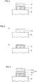
- a semiconductor device has a silicon carbide substrate 90, an electrode layer 16, and a metal pad layer 19.
- Electrode layer 16 lies on silicon carbide substrate 90 in contact therewith and has Ni atoms and Si atoms.
- the number of Ni atoms is not less than 67% of the total number of Ni atoms and Si atoms. More specifically, general composition of a material for electrode layer 16 is a mixture of Ni not lower than 67 atomic % and Si which is a substantial remainder. It is noted that an additive other than Ni and Si may be added to a material for electrode layer 16 as necessary. In addition, a material for electrode layer 16 may contain an inevitable impurity in an industrial manufacturing method.
- the number of Si atoms in electrode layer 16 is not less than 10% of the total number of Ni atoms and Si atoms.
- a side of electrode layer 16 at least in contact with silicon carbide substrate 90 contains a compound of Si and Ni, that is, nickel silicide.
- electrode layer 16 and silicon carbide substrate 90 establish ohmic contact with each other.
- electrode layer 16 has a function as an ohmic electrode.
- the compound above is generally Ni 2 Si.
- a ratio of the number of Ni atoms to the total number of atoms of Ni and Si is approximately 2/3, that is, approximately 67%. This ratio is higher on the surface side (an upper side in the drawing) of electrode layer 16, and in an extreme case, it may be a value close to 100%.
- the surface side of electrode layer 16 may substantially be composed of Ni. In this case, electrical conductivity on the surface side of electrode layer 16 is higher than in a case where Si is significantly contained.
- C atom concentration is lower than Ni atom concentration.
- this C atom concentration is lower than 3% and more preferably lower than 1%.
- substantially no C atom is present on the surface side of electrode layer 16. Namely, aside from deposition of inevitable C atoms from an external environment, the surface side of electrode layer 16 may substantially be composed of Ni.
- atomic concentration on the surface side refers to a ratio of the number of specific atoms to the total number of atoms in a region extending from a surface (an upper surface in the drawing) of electrode layer 16 to a depth of 5 nm.
- This atomic concentration can be measured with element analysis high in resolution in a direction of depth, and it can be measured, for example, with SIMS (Secondary Ion Mass Spectroscopy).
- SIMS Secondary Ion Mass Spectroscopy
- the surface of electrode layer 16 itself is a surface from which no substance has been removed by etching, polishing, or the like.
- the step of forming electrode layer 16 is further simplified. Even in this case, however, a contaminant that has deposited onto the surface of electrode layer 16 from an external environment after electrode layer 16 is formed may be removed. Removal can be achieved, for example, by cleaning as described above.
- Metal pad layer 19 is in contact with the surface side of electrode layer 16.
- metal pad layer 19 is either an Al layer or an Al-Si layer.
- silicon carbide substrate 90 is initially prepared. Then, a material layer 50a lying on silicon carbide substrate 90 in contact therewith and having Ni atoms and Si atoms is formed. The number of Ni atoms is not less than 67% of the total number of Ni atoms and Si atoms.
- Material layer 50a is a mixed layer of Si and Ni. This mixed layer can be formed, for example, by simultaneously sputtering a target composed of Si and a target composed of Ni.
- the number of Si atoms in material layer 50a is not less than 10% of the total number of Ni atoms and Si atoms.
- silicon carbide substrate 90 on which material layer 50a ( Fig. 2(A) ) has been formed is irradiated with laser beams.
- electrode layer 16 ( Fig. 2(B) ) is formed from material layer 50a. This annealing is carried out such that a side of electrode layer 16 at least in contact with silicon carbide substrate 90 contains a compound of Si and Ni, that is, nickel silicide.
- the laser beams have a wavelength not longer than 386 nm, which is a wavelength corresponding to a band gap of silicon carbide.
- laser beams are absorbed in the surface of silicon carbide substrate 90.
- Light beams having a wavelength of 355 nm, which are third harmonics of YAG laser or YVO 4 laser, can be employed as such laser beams.
- Output density of laser beams is not less than 0.5 J/cm 2 and not more than 1.5 J/cm 2 and more preferably not less than 0.7 J/cm 2 and not more than 1.3 J/cm 2 .
- a sufficient annealing function can be obtained and damage due to laser beams can be suppressed.
- Laser beams have a pulse width not less than 10 ns and not more than 10 ⁇ s and more preferably not less than 50 ns and not more than 1 ⁇ s. Thus, annealing can be carried out in a sufficiently short period of time while laser having a practical pulse width is being used.
- metal pad layer 19 is formed on electrode layer 16.
- Metal pad layer 19 is preferably an Al layer.
- the semiconductor device in the present embodiment is obtained as above.
- the number of Ni atoms is not less than 70% and not more than 90% of the total number of Ni atoms and Si atoms.
- this percentage is lower than 67%, electrical conductivity of electrode layer 16 can be enhanced.
- the surface side of electrode layer 16 has C atom concentration lower than the sum of Si atom concentration and Ni atom concentration.
- Si atom concentration on the surface side of electrode layer 16 is lower than 30%.
- electrical conductivity of electrode layer 16 can further be enhanced.
- the number of Ni atoms is not less than 70% and not more than 90% of the total number of Ni atoms and Si atoms.
- this percentage is lower than 67%, electrical conductivity of electrode layer 16 can be enhanced.
- annealing is carried out in a short period of time.
- diffusion of C atoms can be suppressed. Therefore, C atom concentration on the surface side of electrode layer 16 can be lowered.
- metal pad layer 19 in contact with the surface side of electrode layer 16 is formed, metal pad layer 19 is less likely to peel off.
- the number of Ni atoms in electrode layer 16 or material layer 50a is not less than 70% of the total number of Ni atoms and Si atoms. Thus, the function and effect described above can more reliably be obtained. Moreover, the number of Ni atoms is not more than 90% of the total number of Ni atoms and Si atoms. Thus, diffusion of C atoms from silicon carbide substrate 90 can further be suppressed.
- a metal pad layer 19V in a semiconductor device includes an adhesive layer 19a formed on electrode layer 16 and a main body layer 19b formed on adhesive layer 19a.
- Adhesive layer 19a is composed of any of Ti, TiW, and TiN.
- Main body layer 19b is preferably an Al layer or an Al-Si layer.
- adhesion of metal pad layer 19V to electrode layer 16 can further be enhanced.
- a material layer 50b is formed instead of material layer 50a ( Fig. 2(A) ).
- the step of forming material layer 50b includes the step of stacking an Si layer 51 and an Ni layer 52.
- an uppermost layer of the formed stack is Ni layer 52.
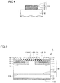
- a semiconductor device in the present embodiment is a vertical MOSFET (Metal Oxide Semiconductor Field Effect Transistor), and it has silicon carbide substrate 90, electrode layer 16, metal pad layer 19, a gate insulating film 15, and a gate electrode 17.
- Silicon carbide substrate 90 has an n + layer 11, an n - layer 12, a p body layer 13, an n + source region 14, and a p + region 18.
- Electrode layer 16 is provided so as to be in ohmic contact with each of n + source region 14 and p + region 18 at one surface (an upper surface in the drawing) of silicon carbide substrate 90. Electrode layer 16 has a thickness, for example, approximately from 100 to 200 nm.
- Gate electrode 17 is provided on one surface (the upper surface in the drawing) of silicon carbide substrate 90 with gate insulating film 15 being interposed, and it is opposed to a channel region 13A which is a surface side of p body layer 13.
- a drain electrode 20 is provided on the other surface (a lower surface in the drawing) of silicon carbide substrate 90.
- a vertical MOSFET having electrode layer 16 high in electrical conductivity and metal pad layer 19 less likely to peel off is obtained.
- a vertical IGBT Insulated Gate Bipolar Transistor
- a vertical MOSFET Insulated Gate Bipolar Transistor
- a structure in which a gate electrode is embedded in a trench formed in a silicon carbide substrate with a gate insulating film being interposed may be employed.
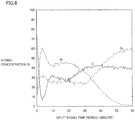
- a comparative example of the present invention will be described with reference to data of a concentration profile using SIMS. Since a metal pad layer was not formed on a surface of a metal layer, a portion in the vicinity of a sputtering time period of 0 in a concentration profile corresponds to a surface of an electrode layer. In addition, a sputtering rate was set to approximately 10 nm/minute. Further, before measurement, surface cleaning treatment was performed. A comparative example will specifically be described below.
- Ni layer was employed instead of material layer 50a.
- lamp annealing was employed instead of laser annealing.
- C atoms occupied half or more of atoms.
- each of C atoms and Si atoms was present at a significant ratio.
- Ni atoms diffused toward a deeper portion, that is, toward the inside of the silicon carbide substrate.
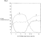
- Such a stack as having Ni of 80 atomic % and Si of 20 atomic % was employed as material layer 50b ( Fig. 4 ).
- lamp annealing was employed instead of laser annealing.
- a layer lower in Ni ratio was employed instead of material layer 50a ( Fig. 2(A) ). Specifically, a mixed layer having composition of Ni of 65 atomic % and Si of 35 atomic % was employed. In addition, lamp annealing was employed instead of laser annealing. Average electrical conductivity of the obtained electrode layer was lower than in the example of the present invention.
- 16 electrode layer 19 metal pad layer; 50a, 50b material layer; 51 Si layer; 52 Ni layer; and 90 silicon carbide substrate.
Landscapes
- Physics & Mathematics (AREA)
- Engineering & Computer Science (AREA)
- Condensed Matter Physics & Semiconductors (AREA)
- General Physics & Mathematics (AREA)
- Manufacturing & Machinery (AREA)
- Computer Hardware Design (AREA)
- Microelectronics & Electronic Packaging (AREA)
- Power Engineering (AREA)
- High Energy & Nuclear Physics (AREA)
- Crystallography & Structural Chemistry (AREA)
- Electromagnetism (AREA)
- Optics & Photonics (AREA)
- Chemical & Material Sciences (AREA)
- Health & Medical Sciences (AREA)
- Toxicology (AREA)
- Electrodes Of Semiconductors (AREA)
Applications Claiming Priority (2)
| Application Number | Priority Date | Filing Date | Title |
|---|---|---|---|
| JP2010245149A JP5418466B2 (ja) | 2010-11-01 | 2010-11-01 | 半導体装置およびその製造方法 |
| PCT/JP2011/073995 WO2012060222A1 (ja) | 2010-11-01 | 2011-10-19 | 半導体装置およびその製造方法 |
Publications (3)
| Publication Number | Publication Date |
|---|---|
| EP2637198A1 EP2637198A1 (en) | 2013-09-11 |
| EP2637198A4 EP2637198A4 (en) | 2014-12-31 |
| EP2637198B1 true EP2637198B1 (en) | 2018-09-26 |
Family
ID=46024339
Family Applications (1)
| Application Number | Title | Priority Date | Filing Date |
|---|---|---|---|
| EP11837873.6A Active EP2637198B1 (en) | 2010-11-01 | 2011-10-19 | Method of manufacturing a semiconductor device |
Country Status (8)
Families Citing this family (18)
| Publication number | Priority date | Publication date | Assignee | Title |
|---|---|---|---|---|
| JP2014003252A (ja) * | 2012-06-21 | 2014-01-09 | Sumitomo Electric Ind Ltd | 炭化珪素半導体装置およびその製造方法 |
| WO2014065018A1 (ja) | 2012-10-23 | 2014-05-01 | 富士電機株式会社 | 半導体装置の製造方法 |
| JP5962475B2 (ja) * | 2012-12-06 | 2016-08-03 | 三菱電機株式会社 | 炭化珪素半導体装置の製造方法及び炭化珪素半導体装置 |
| JP2014123589A (ja) * | 2012-12-20 | 2014-07-03 | Sumitomo Heavy Ind Ltd | 半導体装置の製造方法 |
| JP6350106B2 (ja) * | 2014-08-20 | 2018-07-04 | 住友電気工業株式会社 | 炭化珪素半導体装置 |
| JP2016046309A (ja) * | 2014-08-20 | 2016-04-04 | 住友電気工業株式会社 | 炭化珪素半導体装置の製造方法 |
| JP6323252B2 (ja) * | 2014-08-20 | 2018-05-16 | 住友電気工業株式会社 | 炭化珪素半導体装置の製造方法 |
| JP2016046311A (ja) * | 2014-08-20 | 2016-04-04 | 住友電気工業株式会社 | 炭化珪素半導体装置 |
| JP2016046449A (ja) * | 2014-08-26 | 2016-04-04 | 住友重機械工業株式会社 | 半導体素子の製造方法 |
| JP6425457B2 (ja) * | 2014-08-26 | 2018-11-21 | 住友重機械工業株式会社 | 半導体素子の製造方法 |
| JP6686581B2 (ja) * | 2016-03-16 | 2020-04-22 | 富士電機株式会社 | 炭化珪素半導体素子および炭化珪素半導体素子の製造方法 |
| JP6728097B2 (ja) | 2017-04-24 | 2020-07-22 | 株式会社東芝 | 半導体装置、半導体装置の製造方法、インバータ回路、駆動装置、車両、及び、昇降機 |
| JP6728096B2 (ja) | 2017-04-24 | 2020-07-22 | 株式会社東芝 | 半導体装置、半導体装置の製造方法、インバータ回路、駆動装置、車両、及び、昇降機 |
| DE102019101268A1 (de) * | 2019-01-18 | 2020-07-23 | Psc Technologies Gmbh | Verfahren zur Herstellung oder Modifizierung von siliciumcarbidhaltigen Objekten |
| US12087821B2 (en) | 2019-07-17 | 2024-09-10 | Sumitomo Electric Industries, Ltd. | Method for manufacturing silicon carbide semiconductor device and silicon carbide semiconductor device |
| JP7548232B2 (ja) | 2019-07-17 | 2024-09-10 | 住友電気工業株式会社 | 炭化珪素半導体装置の製造方法及び炭化珪素半導体装置 |
| JP7647216B2 (ja) | 2021-03-22 | 2025-03-18 | 住友電気工業株式会社 | 炭化珪素半導体装置の製造方法 |
| JP2023137581A (ja) * | 2022-03-18 | 2023-09-29 | キオクシア株式会社 | 半導体装置、半導体装置の製造方法 |
Family Cites Families (13)
| Publication number | Priority date | Publication date | Assignee | Title |
|---|---|---|---|---|
| JPS6422026A (en) * | 1987-07-17 | 1989-01-25 | Sony Corp | Manufacture of semiconductor device |
| JP3079851B2 (ja) | 1993-09-28 | 2000-08-21 | 富士電機株式会社 | 炭化けい素電子デバイスの製造方法 |
| US7297626B1 (en) * | 2001-08-27 | 2007-11-20 | United States Of America As Represented By The Secretary Of The Army | Process for nickel silicide Ohmic contacts to n-SiC |
| US20050104072A1 (en) * | 2003-08-14 | 2005-05-19 | Slater David B.Jr. | Localized annealing of metal-silicon carbide ohmic contacts and devices so formed |
| KR100586949B1 (ko) * | 2004-01-19 | 2006-06-07 | 삼성전기주식회사 | 플립칩용 질화물 반도체 발광소자 |
| JP4594113B2 (ja) * | 2005-01-19 | 2010-12-08 | 新電元工業株式会社 | 半導体装置の製造方法 |
| CN101263581B (zh) * | 2005-09-16 | 2010-09-29 | 克里公司 | 其上有碳化硅功率器件的半导体晶圆的处理方法 |
| US20070138482A1 (en) * | 2005-12-08 | 2007-06-21 | Nissan Motor Co., Ltd. | Silicon carbide semiconductor device and method for producing the same |
| JP4140648B2 (ja) * | 2006-11-02 | 2008-08-27 | 住友電気工業株式会社 | SiC半導体用オーミック電極、SiC半導体用オーミック電極の製造方法、半導体装置および半導体装置の製造方法 |
| JP4965576B2 (ja) * | 2007-02-14 | 2012-07-04 | パナソニック株式会社 | 半導体装置及びその製造方法 |
| CN101578705B (zh) * | 2007-07-20 | 2012-05-30 | 松下电器产业株式会社 | 碳化硅半导体装置及其制造方法 |
| JP5091063B2 (ja) * | 2008-09-05 | 2012-12-05 | 三菱電機株式会社 | 半導体装置の製造方法 |
| JP5391643B2 (ja) * | 2008-10-22 | 2014-01-15 | 住友電気工業株式会社 | 炭化珪素半導体装置およびその製造方法 |
-
2010
- 2010-11-01 JP JP2010245149A patent/JP5418466B2/ja active Active
-
2011
- 2011-10-19 CN CN201180013968.2A patent/CN102804342B/zh active Active
- 2011-10-19 KR KR1020127023119A patent/KR20130122898A/ko not_active Withdrawn
- 2011-10-19 WO PCT/JP2011/073995 patent/WO2012060222A1/ja active Application Filing
- 2011-10-19 EP EP11837873.6A patent/EP2637198B1/en active Active
- 2011-10-19 CA CA2790077A patent/CA2790077A1/en not_active Abandoned
- 2011-10-19 US US13/579,482 patent/US8823017B2/en active Active
- 2011-10-25 TW TW100138734A patent/TW201234609A/zh unknown
Non-Patent Citations (1)
| Title |
|---|
| NIKITINA I ET AL: "Formation and role of graphite and nickel silicide in nickel based ohmic contacts to n-type silicon carbide", JOURNAL OF APPLIED PHYSICS, AMERICAN INSTITUTE OF PHYSICS, US, vol. 97, no. 8, 6 April 2005 (2005-04-06), pages 83709 - 083709, XP012071079, ISSN: 0021-8979, DOI: 10.1063/1.1872200 * |
Also Published As
| Publication number | Publication date |
|---|---|
| KR20130122898A (ko) | 2013-11-11 |
| WO2012060222A1 (ja) | 2012-05-10 |
| WO2012060222A9 (ja) | 2012-10-11 |
| CN102804342A (zh) | 2012-11-28 |
| US8823017B2 (en) | 2014-09-02 |
| EP2637198A1 (en) | 2013-09-11 |
| JP2012099598A (ja) | 2012-05-24 |
| CN102804342B (zh) | 2016-08-03 |
| JP5418466B2 (ja) | 2014-02-19 |
| EP2637198A4 (en) | 2014-12-31 |
| TW201234609A (en) | 2012-08-16 |
| US20120319135A1 (en) | 2012-12-20 |
| CA2790077A1 (en) | 2012-05-10 |
Similar Documents
| Publication | Publication Date | Title |
|---|---|---|
| EP2637198B1 (en) | Method of manufacturing a semiconductor device | |
| JP5525940B2 (ja) | 半導体装置および半導体装置の製造方法 | |
| CN110797260B (zh) | 半导体功率器件及其制备方法 | |
| JP6405237B2 (ja) | ゲート電極を有する炭化ケイ素半導体デバイス | |
| JP6099298B2 (ja) | SiC半導体デバイス及びその製造方法 | |
| JP5671867B2 (ja) | 半導体装置およびその製造方法 | |
| EP2698808B1 (en) | Method for manufacturing a silicon carbide semiconductor device | |
| JP4221012B2 (ja) | 半導体装置とその製造方法 | |
| EP2637213A1 (en) | Semiconductor device and manufacturing method therefor | |
| US9768260B2 (en) | Fabrication method of silicon carbide semiconductor apparatus and silicon carbide semiconductor apparatus fabricated thereby | |
| US10249718B2 (en) | Semiconductor device, method for manufacturing semiconductor device, inverter circuit, driving device, vehicle, and elevator | |
| EP2905806A1 (en) | Silicon carbide semiconductor device manufacturing method | |
| US10050133B2 (en) | Application of thin insulating film layer in semiconductor device and method of manufacturing semiconductor device | |
| EP3336879B1 (en) | Method of manufacturing silicon carbide semiconductor device | |
| JP5608358B2 (ja) | 半導体装置とその製造方法 | |
| CN104285299A (zh) | 碳化硅半导体器件 | |
| JP2009076874A (ja) | ショットキーバリアダイオードおよびその製造方法 | |
| US20160314973A1 (en) | Method of manufacturing silicon carbide semiconductor device | |
| JP2005079233A (ja) | ショットキーダイオードとその製造方法 | |
| Xia | Investigation of Ultra-Wide Bandgap Semiconductors and SICxNy Coatings for Advanced Dental Implant Applications | |
| Placidi et al. | Ohmic Contacts to implanted GaN | |
| EA026882B1 (ru) | Диод шоттки |
Legal Events
| Date | Code | Title | Description |
|---|---|---|---|
| PUAI | Public reference made under article 153(3) epc to a published international application that has entered the european phase |
Free format text: ORIGINAL CODE: 0009012 |
|
| 17P | Request for examination filed |
Effective date: 20120816 |
|
| AK | Designated contracting states |
Kind code of ref document: A1 Designated state(s): AL AT BE BG CH CY CZ DE DK EE ES FI FR GB GR HR HU IE IS IT LI LT LU LV MC MK MT NL NO PL PT RO RS SE SI SK SM TR |
|
| DAX | Request for extension of the european patent (deleted) | ||
| A4 | Supplementary search report drawn up and despatched |
Effective date: 20141203 |
|
| RIC1 | Information provided on ipc code assigned before grant |
Ipc: H01L 21/28 20060101AFI20141127BHEP Ipc: H01L 29/12 20060101ALI20141127BHEP Ipc: H01L 21/336 20060101ALI20141127BHEP Ipc: H01L 29/78 20060101ALI20141127BHEP Ipc: H01L 21/268 20060101ALI20141127BHEP |
|
| 17Q | First examination report despatched |
Effective date: 20160726 |
|
| STAA | Information on the status of an ep patent application or granted ep patent |
Free format text: STATUS: EXAMINATION IS IN PROGRESS |
|
| GRAP | Despatch of communication of intention to grant a patent |
Free format text: ORIGINAL CODE: EPIDOSNIGR1 |
|
| STAA | Information on the status of an ep patent application or granted ep patent |
Free format text: STATUS: GRANT OF PATENT IS INTENDED |
|
| RIC1 | Information provided on ipc code assigned before grant |
Ipc: H01L 21/28 20060101AFI20180315BHEP Ipc: H01L 21/268 20060101ALI20180315BHEP Ipc: H01L 21/336 20060101ALI20180315BHEP Ipc: H01L 29/16 20060101ALI20180315BHEP Ipc: H01L 29/78 20060101ALI20180315BHEP |
|
| INTG | Intention to grant announced |
Effective date: 20180416 |
|
| RIN1 | Information on inventor provided before grant (corrected) |
Inventor name: TAMASO, HIDETO |
|
| GRAS | Grant fee paid |
Free format text: ORIGINAL CODE: EPIDOSNIGR3 |
|
| GRAA | (expected) grant |
Free format text: ORIGINAL CODE: 0009210 |
|
| STAA | Information on the status of an ep patent application or granted ep patent |
Free format text: STATUS: THE PATENT HAS BEEN GRANTED |
|
| AK | Designated contracting states |
Kind code of ref document: B1 Designated state(s): AL AT BE BG CH CY CZ DE DK EE ES FI FR GB GR HR HU IE IS IT LI LT LU LV MC MK MT NL NO PL PT RO RS SE SI SK SM TR |
|
| REG | Reference to a national code |
Ref country code: GB Ref legal event code: FG4D |
|
| REG | Reference to a national code |
Ref country code: CH Ref legal event code: EP |
|
| REG | Reference to a national code |
Ref country code: AT Ref legal event code: REF Ref document number: 1047013 Country of ref document: AT Kind code of ref document: T Effective date: 20181015 |
|
| REG | Reference to a national code |
Ref country code: IE Ref legal event code: FG4D |
|
| REG | Reference to a national code |
Ref country code: DE Ref legal event code: R096 Ref document number: 602011052431 Country of ref document: DE |
|
| REG | Reference to a national code |
Ref country code: NL Ref legal event code: MP Effective date: 20180926 |
|
| PG25 | Lapsed in a contracting state [announced via postgrant information from national office to epo] |
Ref country code: GR Free format text: LAPSE BECAUSE OF FAILURE TO SUBMIT A TRANSLATION OF THE DESCRIPTION OR TO PAY THE FEE WITHIN THE PRESCRIBED TIME-LIMIT Effective date: 20181227 Ref country code: SE Free format text: LAPSE BECAUSE OF FAILURE TO SUBMIT A TRANSLATION OF THE DESCRIPTION OR TO PAY THE FEE WITHIN THE PRESCRIBED TIME-LIMIT Effective date: 20180926 Ref country code: BG Free format text: LAPSE BECAUSE OF FAILURE TO SUBMIT A TRANSLATION OF THE DESCRIPTION OR TO PAY THE FEE WITHIN THE PRESCRIBED TIME-LIMIT Effective date: 20181226 Ref country code: RS Free format text: LAPSE BECAUSE OF FAILURE TO SUBMIT A TRANSLATION OF THE DESCRIPTION OR TO PAY THE FEE WITHIN THE PRESCRIBED TIME-LIMIT Effective date: 20180926 Ref country code: NO Free format text: LAPSE BECAUSE OF FAILURE TO SUBMIT A TRANSLATION OF THE DESCRIPTION OR TO PAY THE FEE WITHIN THE PRESCRIBED TIME-LIMIT Effective date: 20181226 Ref country code: FI Free format text: LAPSE BECAUSE OF FAILURE TO SUBMIT A TRANSLATION OF THE DESCRIPTION OR TO PAY THE FEE WITHIN THE PRESCRIBED TIME-LIMIT Effective date: 20180926 Ref country code: LT Free format text: LAPSE BECAUSE OF FAILURE TO SUBMIT A TRANSLATION OF THE DESCRIPTION OR TO PAY THE FEE WITHIN THE PRESCRIBED TIME-LIMIT Effective date: 20180926 |
|
| REG | Reference to a national code |
Ref country code: LT Ref legal event code: MG4D |
|
| PG25 | Lapsed in a contracting state [announced via postgrant information from national office to epo] |
Ref country code: AL Free format text: LAPSE BECAUSE OF FAILURE TO SUBMIT A TRANSLATION OF THE DESCRIPTION OR TO PAY THE FEE WITHIN THE PRESCRIBED TIME-LIMIT Effective date: 20180926 Ref country code: LV Free format text: LAPSE BECAUSE OF FAILURE TO SUBMIT A TRANSLATION OF THE DESCRIPTION OR TO PAY THE FEE WITHIN THE PRESCRIBED TIME-LIMIT Effective date: 20180926 Ref country code: HR Free format text: LAPSE BECAUSE OF FAILURE TO SUBMIT A TRANSLATION OF THE DESCRIPTION OR TO PAY THE FEE WITHIN THE PRESCRIBED TIME-LIMIT Effective date: 20180926 |
|
| REG | Reference to a national code |
Ref country code: AT Ref legal event code: MK05 Ref document number: 1047013 Country of ref document: AT Kind code of ref document: T Effective date: 20180926 |
|
| PG25 | Lapsed in a contracting state [announced via postgrant information from national office to epo] |
Ref country code: NL Free format text: LAPSE BECAUSE OF FAILURE TO SUBMIT A TRANSLATION OF THE DESCRIPTION OR TO PAY THE FEE WITHIN THE PRESCRIBED TIME-LIMIT Effective date: 20180926 Ref country code: PL Free format text: LAPSE BECAUSE OF FAILURE TO SUBMIT A TRANSLATION OF THE DESCRIPTION OR TO PAY THE FEE WITHIN THE PRESCRIBED TIME-LIMIT Effective date: 20180926 Ref country code: IS Free format text: LAPSE BECAUSE OF FAILURE TO SUBMIT A TRANSLATION OF THE DESCRIPTION OR TO PAY THE FEE WITHIN THE PRESCRIBED TIME-LIMIT Effective date: 20190126 Ref country code: ES Free format text: LAPSE BECAUSE OF FAILURE TO SUBMIT A TRANSLATION OF THE DESCRIPTION OR TO PAY THE FEE WITHIN THE PRESCRIBED TIME-LIMIT Effective date: 20180926 Ref country code: CZ Free format text: LAPSE BECAUSE OF FAILURE TO SUBMIT A TRANSLATION OF THE DESCRIPTION OR TO PAY THE FEE WITHIN THE PRESCRIBED TIME-LIMIT Effective date: 20180926 Ref country code: IT Free format text: LAPSE BECAUSE OF FAILURE TO SUBMIT A TRANSLATION OF THE DESCRIPTION OR TO PAY THE FEE WITHIN THE PRESCRIBED TIME-LIMIT Effective date: 20180926 Ref country code: RO Free format text: LAPSE BECAUSE OF FAILURE TO SUBMIT A TRANSLATION OF THE DESCRIPTION OR TO PAY THE FEE WITHIN THE PRESCRIBED TIME-LIMIT Effective date: 20180926 Ref country code: AT Free format text: LAPSE BECAUSE OF FAILURE TO SUBMIT A TRANSLATION OF THE DESCRIPTION OR TO PAY THE FEE WITHIN THE PRESCRIBED TIME-LIMIT Effective date: 20180926 Ref country code: EE Free format text: LAPSE BECAUSE OF FAILURE TO SUBMIT A TRANSLATION OF THE DESCRIPTION OR TO PAY THE FEE WITHIN THE PRESCRIBED TIME-LIMIT Effective date: 20180926 |
|
| PG25 | Lapsed in a contracting state [announced via postgrant information from national office to epo] |
Ref country code: SK Free format text: LAPSE BECAUSE OF FAILURE TO SUBMIT A TRANSLATION OF THE DESCRIPTION OR TO PAY THE FEE WITHIN THE PRESCRIBED TIME-LIMIT Effective date: 20180926 Ref country code: SM Free format text: LAPSE BECAUSE OF FAILURE TO SUBMIT A TRANSLATION OF THE DESCRIPTION OR TO PAY THE FEE WITHIN THE PRESCRIBED TIME-LIMIT Effective date: 20180926 Ref country code: PT Free format text: LAPSE BECAUSE OF FAILURE TO SUBMIT A TRANSLATION OF THE DESCRIPTION OR TO PAY THE FEE WITHIN THE PRESCRIBED TIME-LIMIT Effective date: 20190126 |
|
| REG | Reference to a national code |
Ref country code: CH Ref legal event code: PL |
|
| REG | Reference to a national code |
Ref country code: BE Ref legal event code: MM Effective date: 20181031 |
|
| REG | Reference to a national code |
Ref country code: DE Ref legal event code: R097 Ref document number: 602011052431 Country of ref document: DE |
|
| PG25 | Lapsed in a contracting state [announced via postgrant information from national office to epo] |
Ref country code: LU Free format text: LAPSE BECAUSE OF NON-PAYMENT OF DUE FEES Effective date: 20181019 |
|
| REG | Reference to a national code |
Ref country code: IE Ref legal event code: MM4A |
|
| PG25 | Lapsed in a contracting state [announced via postgrant information from national office to epo] |
Ref country code: DK Free format text: LAPSE BECAUSE OF FAILURE TO SUBMIT A TRANSLATION OF THE DESCRIPTION OR TO PAY THE FEE WITHIN THE PRESCRIBED TIME-LIMIT Effective date: 20180926 Ref country code: MC Free format text: LAPSE BECAUSE OF FAILURE TO SUBMIT A TRANSLATION OF THE DESCRIPTION OR TO PAY THE FEE WITHIN THE PRESCRIBED TIME-LIMIT Effective date: 20180926 |
|
| PLBE | No opposition filed within time limit |
Free format text: ORIGINAL CODE: 0009261 |
|
| STAA | Information on the status of an ep patent application or granted ep patent |
Free format text: STATUS: NO OPPOSITION FILED WITHIN TIME LIMIT |
|
| GBPC | Gb: european patent ceased through non-payment of renewal fee |
Effective date: 20181226 |
|
| PG25 | Lapsed in a contracting state [announced via postgrant information from national office to epo] |
Ref country code: CH Free format text: LAPSE BECAUSE OF NON-PAYMENT OF DUE FEES Effective date: 20181031 Ref country code: BE Free format text: LAPSE BECAUSE OF NON-PAYMENT OF DUE FEES Effective date: 20181031 Ref country code: LI Free format text: LAPSE BECAUSE OF NON-PAYMENT OF DUE FEES Effective date: 20181031 |
|
| 26N | No opposition filed |
Effective date: 20190627 |
|
| PG25 | Lapsed in a contracting state [announced via postgrant information from national office to epo] |
Ref country code: FR Free format text: LAPSE BECAUSE OF NON-PAYMENT OF DUE FEES Effective date: 20181126 Ref country code: SI Free format text: LAPSE BECAUSE OF FAILURE TO SUBMIT A TRANSLATION OF THE DESCRIPTION OR TO PAY THE FEE WITHIN THE PRESCRIBED TIME-LIMIT Effective date: 20180926 Ref country code: IE Free format text: LAPSE BECAUSE OF NON-PAYMENT OF DUE FEES Effective date: 20181019 |
|
| PG25 | Lapsed in a contracting state [announced via postgrant information from national office to epo] |
Ref country code: GB Free format text: LAPSE BECAUSE OF NON-PAYMENT OF DUE FEES Effective date: 20181226 |
|
| PG25 | Lapsed in a contracting state [announced via postgrant information from national office to epo] |
Ref country code: MT Free format text: LAPSE BECAUSE OF NON-PAYMENT OF DUE FEES Effective date: 20181019 |
|
| PG25 | Lapsed in a contracting state [announced via postgrant information from national office to epo] |
Ref country code: TR Free format text: LAPSE BECAUSE OF FAILURE TO SUBMIT A TRANSLATION OF THE DESCRIPTION OR TO PAY THE FEE WITHIN THE PRESCRIBED TIME-LIMIT Effective date: 20180926 |
|
| PG25 | Lapsed in a contracting state [announced via postgrant information from national office to epo] |
Ref country code: HU Free format text: LAPSE BECAUSE OF FAILURE TO SUBMIT A TRANSLATION OF THE DESCRIPTION OR TO PAY THE FEE WITHIN THE PRESCRIBED TIME-LIMIT; INVALID AB INITIO Effective date: 20111019 Ref country code: CY Free format text: LAPSE BECAUSE OF FAILURE TO SUBMIT A TRANSLATION OF THE DESCRIPTION OR TO PAY THE FEE WITHIN THE PRESCRIBED TIME-LIMIT Effective date: 20180926 Ref country code: MK Free format text: LAPSE BECAUSE OF NON-PAYMENT OF DUE FEES Effective date: 20180926 |
|
| P01 | Opt-out of the competence of the unified patent court (upc) registered |
Effective date: 20230515 |
|
| REG | Reference to a national code |
Ref country code: DE Ref legal event code: R079 Ref document number: 602011052431 Country of ref document: DE Free format text: PREVIOUS MAIN CLASS: H01L0021280000 Ipc: H10D0064010000 |
|
| PGFP | Annual fee paid to national office [announced via postgrant information from national office to epo] |
Ref country code: DE Payment date: 20240828 Year of fee payment: 14 |