EP2637181B1 - Multi orientation cryostats - Google Patents
Multi orientation cryostats Download PDFInfo
- Publication number
- EP2637181B1 EP2637181B1 EP12158274.6A EP12158274A EP2637181B1 EP 2637181 B1 EP2637181 B1 EP 2637181B1 EP 12158274 A EP12158274 A EP 12158274A EP 2637181 B1 EP2637181 B1 EP 2637181B1
- Authority
- EP
- European Patent Office
- Prior art keywords
- orientation
- cryostat
- quench duct
- vessel
- quench
- Prior art date
- Legal status (The legal status is an assumption and is not a legal conclusion. Google has not performed a legal analysis and makes no representation as to the accuracy of the status listed.)
- Active
Links
- 238000010791 quenching Methods 0.000 claims description 116
- 239000007788 liquid Substances 0.000 claims description 22
- 230000000171 quenching effect Effects 0.000 claims description 8
- 238000000034 method Methods 0.000 claims description 3
- 230000009466 transformation Effects 0.000 claims description 3
- 238000009835 boiling Methods 0.000 claims 1
- 239000007789 gas Substances 0.000 description 15
- BGPVFRJUHWVFKM-UHFFFAOYSA-N N1=C2C=CC=CC2=[N+]([O-])C1(CC1)CCC21N=C1C=CC=CC1=[N+]2[O-] Chemical compound N1=C2C=CC=CC2=[N+]([O-])C1(CC1)CCC21N=C1C=CC=CC1=[N+]2[O-] BGPVFRJUHWVFKM-UHFFFAOYSA-N 0.000 description 6
- 239000012530 fluid Substances 0.000 description 4
- 230000005484 gravity Effects 0.000 description 4
- 230000000694 effects Effects 0.000 description 3
- 238000005057 refrigeration Methods 0.000 description 3
- 238000002661 proton therapy Methods 0.000 description 2
- 238000001959 radiotherapy Methods 0.000 description 2
- 230000003068 static effect Effects 0.000 description 2
- 238000010792 warming Methods 0.000 description 2
- 238000004804 winding Methods 0.000 description 2
- 230000002159 abnormal effect Effects 0.000 description 1
- WYTGDNHDOZPMIW-RCBQFDQVSA-N alstonine Natural products C1=CC2=C3C=CC=CC3=NC2=C2N1C[C@H]1[C@H](C)OC=C(C(=O)OC)[C@H]1C2 WYTGDNHDOZPMIW-RCBQFDQVSA-N 0.000 description 1
- 238000004891 communication Methods 0.000 description 1
- 238000010276 construction Methods 0.000 description 1
- 239000002826 coolant Substances 0.000 description 1
- 238000001816 cooling Methods 0.000 description 1
- 239000000110 cooling liquid Substances 0.000 description 1
- 238000013461 design Methods 0.000 description 1
- 239000001307 helium Substances 0.000 description 1
- 229910052734 helium Inorganic materials 0.000 description 1
- SWQJXJOGLNCZEY-UHFFFAOYSA-N helium atom Chemical compound [He] SWQJXJOGLNCZEY-UHFFFAOYSA-N 0.000 description 1
- 238000009413 insulation Methods 0.000 description 1
- 239000000463 material Substances 0.000 description 1
- 238000012546 transfer Methods 0.000 description 1
- 230000007704 transition Effects 0.000 description 1
- 238000013022 venting Methods 0.000 description 1
Images


Classifications
-
- F—MECHANICAL ENGINEERING; LIGHTING; HEATING; WEAPONS; BLASTING
- F17—STORING OR DISTRIBUTING GASES OR LIQUIDS
- F17C—VESSELS FOR CONTAINING OR STORING COMPRESSED, LIQUEFIED OR SOLIDIFIED GASES; FIXED-CAPACITY GAS-HOLDERS; FILLING VESSELS WITH, OR DISCHARGING FROM VESSELS, COMPRESSED, LIQUEFIED, OR SOLIDIFIED GASES
- F17C1/00—Pressure vessels, e.g. gas cylinder, gas tank, replaceable cartridge
-
- H—ELECTRICITY
- H01—ELECTRIC ELEMENTS
- H01F—MAGNETS; INDUCTANCES; TRANSFORMERS; SELECTION OF MATERIALS FOR THEIR MAGNETIC PROPERTIES
- H01F6/00—Superconducting magnets; Superconducting coils
- H01F6/02—Quenching; Protection arrangements during quenching
-
- A—HUMAN NECESSITIES
- A61—MEDICAL OR VETERINARY SCIENCE; HYGIENE
- A61N—ELECTROTHERAPY; MAGNETOTHERAPY; RADIATION THERAPY; ULTRASOUND THERAPY
- A61N5/00—Radiation therapy
- A61N5/10—X-ray therapy; Gamma-ray therapy; Particle-irradiation therapy
- A61N5/1077—Beam delivery systems
-
- A—HUMAN NECESSITIES
- A61—MEDICAL OR VETERINARY SCIENCE; HYGIENE
- A61N—ELECTROTHERAPY; MAGNETOTHERAPY; RADIATION THERAPY; ULTRASOUND THERAPY
- A61N5/00—Radiation therapy
- A61N5/10—X-ray therapy; Gamma-ray therapy; Particle-irradiation therapy
- A61N5/1077—Beam delivery systems
- A61N5/1081—Rotating beam systems with a specific mechanical construction, e.g. gantries
-
- H—ELECTRICITY
- H01—ELECTRIC ELEMENTS
- H01F—MAGNETS; INDUCTANCES; TRANSFORMERS; SELECTION OF MATERIALS FOR THEIR MAGNETIC PROPERTIES
- H01F6/00—Superconducting magnets; Superconducting coils
- H01F6/04—Cooling
-
- A—HUMAN NECESSITIES
- A61—MEDICAL OR VETERINARY SCIENCE; HYGIENE
- A61N—ELECTROTHERAPY; MAGNETOTHERAPY; RADIATION THERAPY; ULTRASOUND THERAPY
- A61N5/00—Radiation therapy
- A61N5/10—X-ray therapy; Gamma-ray therapy; Particle-irradiation therapy
- A61N2005/1085—X-ray therapy; Gamma-ray therapy; Particle-irradiation therapy characterised by the type of particles applied to the patient
- A61N2005/1087—Ions; Protons
Definitions
- This invention relates to multi orientation cryostats, and superconducting magnet arrangements including such cryostats, as well as medical equipment apparatus including such cryostats.
- Superconducting magnets are generally required to be maintained at a "low temperature” in order to maintain their superconducting properties.
- Cryostats are provided for maintaining superconducting magnets at superconducting temperatures.
- a cryostat comprises a vessel for holding a cryogenic liquid to act as a coolant. Refrigeration systems will be provided to cool the carried cryogenic liquid and/or cool replacement liquid for feeding to the cryostat.
- Superconducting magnets are typically at risk of quenching.
- Superconducting magnets typically embody very large stored energy in their magnetic fields (e.g. 1MJ and upwards).
- a tiny energy disturbance (1mJ or less) may drive part of the coil above its local superconducting transition temperature into the normal resistive state. If the disturbance exceeds a stability threshold it will propagate through the windings until some or all of them become resistive.
- the stored magnetic energy is then rapidly converted to heat in the resistive windings. The heat leads to rapid boil off of the cryogenic liquid, which is converted to gas, and expands significantly as it warms (for example 700:1 for liquid helium at 4.2K expanding to become gas at room temperature and atmospheric pressure).
- Quenching is expensive and undesirable. The risk of quenching can be minimised by good design and good practice but nevertheless superconducting magnets must be designed to survive quenching, including avoiding over pressure of the vessel of the cryostat carrying the cryogenic cooling liquid.
- a quench duct which provides a path by which rapidly expanding and warming cryogenic fluid, and more particularly cryogenic gas, can escape the vessel.
- Quench ducts need to be relatively wide bored to allow the expanding gas produced by a quench to safely escape the cryostat vessel.
- a fill tube or normal vent tube which is provided in a cryostat for normal operation of the magnet will generally be of much smaller cross sectional area. This is because there is not the need to provide such a tube with a large bore and a large bore is generally undesirable as it will tend to increase heat leakage into the cryostat.
- a quench duct which is distinct from any fill tube.
- the quench duct will be distinct from any vent tube, or at the very least there will be a different outlet end for any present vent tube than the quench duct.
- a quench duct is identifiably different from a fill tube or a normal vent tube.
- the quench duct needs to be of a relatively wide bore it can generate a problem in terms of it being a heat leakage path into the cryostat and can cause undesirable warming of the cryogenic liquid.
- a conventional quench duct has an anti-convection portion which will function when correctly orientated and in use, by virtue of the temperature inversion. This is important because otherwise convection currents will tend to transfer heat into the cryostat.
- This arrangement can function well in a normal superconducting magnet arrangement.
- the superconducting magnet arrangement will be mounted in such a way that it is movable relative to a base of the equipment in which it is installed such that the orientation of the superconducting magnet, and hence cryostat, changes as the superconducting magnet arrangement is moved.
- the equipment may be medical equipment apparatus.
- One example of such a machine is a gantry mounted cyclotron used to provide proton therapy treatment.
- the cyclotron (including the superconducting magnet arrangement) moves in an approximately 180 degree arc around a patient and correspondingly the orientation of the superconducting magnet arrangement and cryostat changes through 180 degrees between one end of this arc and the other.
- the present invention is aimed at addressing at least some of these issues.
- US 4,633,125 describes a vented 360 degree rotatable cryostat.
- a plurality of vent tubes are provided which are wrapped around the vessel. In different orientations different ones of the tubes fill with liquid whilst others act as vents.
- a multi-orientation cryostat for a superconducting magnet for use in a plurality of orientations, as claimed in claim 1.
- This arrangement allows the provision of a quench duct which can operate effectively with the cryostat in multiple orientations whilst providing good insulation performance to minimise the cooling requirement for the carried cryogenic liquid.
- a burst disc may be provided at or towards an end of the quench duct remote from the vessel.
- the quench duct may be distinct from any fill tube and may be distinct from any vent tube or at least the quench duct may have a separate outlet to the vent tube outlet.
- Vent and fill tubes will typically have a smaller cross section than the quench duct since vent and fill tubes are not required to handle the large volume of quickly expanding gas which will be produced during quenching of the cooled magnet.
- the quench duct may comprise more than two anti-convection portions.
- the orientation of at least one of the anti-convection portions may be separated by at least 90 degrees from the orientation of at least another one of the anti-convection portions.
- Each of the anti-convection portions may run in the same plane as the other anti-convection portions or in parallel planes.
- the plane or parallel planes may have the axis of rotation as a normal.
- a first portion of the quench duct may act as an anti-convection portion when the cryostat is in the first orientation and a second portion of the quench duct may act as an anti-convection portion when the cryostat is in the second orientation.
- the quench duct may have three anti-convection portions with a first portion of the quench duct acting as an anti-convection portion when the cryostat is in the first orientation, a second portion of the quench duct acting as an anti-convection portion when the cryostat is in the second orientation, and a third portion of the quench duct acting as an anti-convection portion when the cryostat is in an orientation between the first orientation and the second orientation.
- the quench duct may include a continuous bend portion, such as a u-bend portion, or a loop portion, or a spiral bend portion, the continuous bend portion may turn through at least 90 degrees, preferable in the order of at least 180 degrees and possibly 360 degrees. Selected parts of the continuous bend portion may act as anti-convection portions when the cryostat is in corresponding selected orientations.
- each anti-convection portion When in an operative position, each anti-convection portion will extend upwardly having a lower end and an upper end with the lower end closer, in terms of a flow path through the quench duct from the vessel, to the vessel than the upper end.
- the quench duct may be arranged such that when the multi-orientation cryostat is in any one of the first orientation, the second orientation and the orientations between the first orientation and the second orientation, the quench duct provides a tube portion extending upwardly having a lower end and an upper end with the lower end closer, in terms of a flow path through the quench duct from the vessel, to the vessel than the upper end, to act as an anti-convection portion.
- the cryostat may comprise a single quench duct.
- the multi-orientation cryostat may be a rotatable cryostat.
- a superconducting magnet arrangement comprising a superconducting magnet and multi-orientation cryostat as defined above.
- medical equipment apparatus comprising a superconducting magnet arrangement as defined above mounted for movement relative to a base of the medical equipment apparatus between a first position where the cryostat is in said first orientation and a second position where the cryostat is in said second orientation.
- the quench duct may comprise a plurality of anti-convection portions each for functioning as an anti-convection portion when the cryostat is in a respective corresponding orientation.
- FIG 1 schematically shows medical equipment apparatus which may, for example, be a gantry mounted cyclotron for use in proton therapy treatment or more generally radiotherapy (radiation therapy) apparatus.
- the apparatus comprises a base 1 which supports a superconducting magnet arrangement 2 for movement about an axis 3.
- the superconducting magnet arrangement 2 may be moved between a first position shown in dotted lines and labelled 2' in Figure 1 , and a second position also shown in dotted lines and labelled 2" in Figure 1 by rotation about the axis 3. It will be appreciated that when the superconducting magnet arrangement 2 is in the first position 2' it has a different orientation relative to the base 1 (as well as relative to the surroundings and in particular relative to gravity) than when the superconducting magnet arrangement is in the second position 2".
- the superconducting magnet arrangement 2 can be considered to have a first orientation when in the first position 2', and a second orientation when in the second position 2". Further the superconducting magnet arrangement 2 will have a range of intermediate orientations when the superconducting magnet arrangement 2 is between these two positions.
- the superconducting magnet arrangement 2 comprises a superconducting magnet 4 and a cryostat 5 for holding cryogenic liquid to maintain the magnet 4 at superconducting temperatures.
- the cryostat 5 comprises a vessel 6 and quench duct 7.
- the vessel 6 is for holding the cryogenic liquid, and as mentioned in the introduction, the quench duct 7 is provided for allowing escape of cryogenic fluid and in particular quickly expanding cryogenic gas in the event of the magnet 4 experiencing a quench.
- the interior of the quench duct 7 is in fluid communication with the vessel 6.
- the end of the quench duct 7 where it meets the vessel 6 is open. Thus the quench duct will tend to fill with cryogenic gas in normal operation.
- An alternative arrangement with which the present invention is not concerned is to provide a seal or burst disc at the lower end of the quench duct and evacuate the quench duct. In practice this is difficult and expensive to achieve and the present techniques avoid needing to attempt this.
- the cryostat 5 also comprises a fill tube and a vent tube to allow normal filling of the cryostat with cryogenic liquid and normal venting of the vessel 6.
- a quench duct 7 typically has a relatively large cross section to allow escape of gas during quenching of the magnet 4.
- the quench duct 7 may be a relatively large diameter tube. This is true in the present embodiment.
- the outlet end of the tube is capped with a burst disc (not shown in Figure 1 ) which is designed to rupture at a set over pressure.
- a burst disc (not shown in Figure 1 ) which is designed to rupture at a set over pressure.
- the quench duct 7 is shown only in highly schematic form in Figure 1 and more details of possible configurations of the quench duct 7 will now be described below with reference to the remaining Figures.
- FIG 2 shows a conventional cryostat 5 with a vessel 6 carrying carrying cryogenic liquid 61 and conventional quench duct 7.
- the quench duct 7 is a straight tube. Where this type of quench duct 7 is used in a static superconducting magnet arrangement no particular problems should occur.
- the quench duct 7 would be arranged vertically or near vertically providing a temperature inversion in the quench duct such that the quench duct 7 acts as an anti-convection portion. Cryogenic gas boiled off from the cryogenic liquid 61 will fill the quench duct 7 but the gas will remain essentially static due to the temperature inversion.
- cryostat 5 in an apparatus of the type shown in Figure 1 then in one or at least some of the orientations described in relation to Figure 1 the quench duct 7 will behave in the desired way. However in other orientations it will not. Thus, for example, if the cryostat 5 is orientated so that the quench duct 7 is vertical or near vertical when the superconducting magnet arrangement 2 is in the intermediate position as shown in solid lines in Figure 1 , then when the magnet arrangement 2 is moved to either the first position 2' or second position 2" shown in dotted lines then the quench duct 7 will become near horizontal.
- Figure 2 where the direction of gravity g is indicated with an arrow. In this orientation a convection cell is set up which will tend to allow heat to leak into the vessel 6 increasing boil off as discussed in the introduction above.
- FIGS 3A to 3C through to Figures 6A to 6C show alternative cryostats 5 which are arranged as multi orientation or rotatable cryostats for alleviating this problem.
- Each of these cryostats 5 shown in Figures 3A to 3C through to Figures 6A to 6C are of a type which may be used in the apparatus shown in Figure 1 .
- cryostat 5 is shown in three different orientations.
- Figure XA shows the cryostat in an orientation which corresponds to the superconducting magnet arrangement 2 being in the first position 2' shown in Figure 1
- Figure XB shows the cryostat 5 in an orientation which corresponds to the superconducting magnet arrangement 2 being in the second position 2" shown in Figure 1
- Figure XC shows the cryostat 5 in an orientation which corresponds to the superconducting magnet arrangement 2 being in the intermediate position shown in solid lines in Figure 1 .
- the vessel 6 holds cryogenic liquid 61, and an inlet end 72 of the quench duct 7 meets with and is open to this vessel 6.
- the other end of the quench duct 7 must proceed to the exterior of the magnet arrangement 2 so as to allow escape of cryogenic gas generated during quenching of the magnet 4 should this occur.
- This other, outlet, end is capped with a burst disc 73 and in all normal circumstances there will be cryogenic gas present in the quench duct 7.
- Portions of the quench duct nearer to the vessel 6 will be at a lower temperature than portions away from the vessel 6.
- the gas nearer the burst disc 73 will be warmer than that nearer the vessel 6.
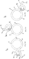
- FIGS 3A to 3C show a first rotatable cryostat 5 which embodies the invention and is suitable for use in the apparatus of Figure 1 .
- the cryostat 5 includes a sinuous (or serpentine) quench duct 7 which is arranged to provide anti-convection portions 71 when the cryostat 5 is in the first orientation as shown in Figures 3A corresponding to the first position 2' of the magnet arrangement 2 in Figure 1 , and when in a second orientation as shown in Figure 3B corresponding to the magnet arrangement 2 being in the second position 2" shown in Figure 1 , as well as in a third orientation as shown in Figure 3C corresponding to the magnet arrangement 2 being in the intermediate position shown in solid lines in Figure 1 .
- the anti convection portion 71 is a portion of the quench duct 7 in which a temperature inversion will exist in use in a corresponding orientation.
- the quench duct 7 includes a 360 degree loop portion 74 which as seen by reference 3A, 3B and 3C provides an anti-convection portion 71 for use in each of the illustrated operational orientations of the cryostat 5. Further, it will be noted that in intermediate orientations between the orientations shown in Figures 3A, 3B and 3C , other portions of the 360 degree loop portion 74 will act as anti-convection portions. An anti-convection portion is provided for each operational orientation of the cryostat 5.
- the anti-convection portion is a portion of the quench duct 7 which is upwardly orientated and may be vertical or substantially vertical and which has a lower end 71a which is nearer (in terms of the flow path from the vessel through the quench duct 7) to the vessel 6 than its upper end 71b.
- This configuration gives rise to the desired temperature inversion in use.
- each anti-convection portion 71 is a portion of duct tubing. It is open and free of any impediments to fluid flow. This is so it can provide its function as part of the quench duct when required.
- a loop portion for example the 360 degree loop portion 74 in the quench duct 7, is desirable because it means that as the cryostat 6 moves from the first orientation shown in Figure 3A to the second orientation shown in Figure 3B through the intermediate orientation shown in Figure 3C the effective anti-convection portion 71 moves smoothly around the loop portion 74. This helps to provide a more continuous anti-convection effect than if the effective anti-convection portion jumps from location to location since in such a case there will be more of time required in order for the flow to stabilise as the temperature inversion takes effect in any given orientation.
- cryostat shown in Figures 3A to 3C provides good operation in orientations of plus or minus 110 degrees from a central position as shown in Figure 3C .
- Figures 4A to 4C show a similar cryostat 5 to that shown in Figures 3A to 3C .
- the loop portion 74 is replaced by a spiral portion 75.
- anti-convection portions 71 are provided by the quench duct 7 for each of the three different orientations shown.
- different anti-convection portions exist for intermediate orientations between those shown in Figures 4A to 4C .
- the loop portion 74 is provided close to parallel to a plane which has the axis of rotation 3 as normal.
- the spiral bend portion 75 of the Figure 4A to 4C arrangement is approximately perpendicular to this plane.
- FIGS 5A to 5C show a third cryostat 5 embodying the present invention.
- the quench duct 7 includes a U-bend portion 76 in place of the loop portion 74 of the quench duct of Figures 3A to 3C .
- this U-bend 76 is provided largely in a plane which has as a normal axis of rotation 2.
- the quench duct 7 again provides anti-convection portions 71 which are operative in the different orientations of the cryostat 5 shown in Figures 5A, 5B and 5C . Again anti-convection portions exist for orientations between these orientations.
- the inlet portion 72 of the quench duct 7 acts as an anti-convection portion for at least one orientation. This is desirable and may indeed be typical but is not essential.
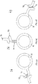
- FIGS 6A to 6C show a fourth cryostat 5 embodying the present invention.
- a vessel 6 shown only highly schematically and in dotted lines in the drawings
- the quench duct 7 is even more convoluted or more sinuous than in the embodiments described above.
- This quench duct 7 includes multiple turns 77 and straight sections 78 therebetween.
- each turn 77 is in the form of a U-bend.
- the quench duct 7 is provided primarily in a plane which has as a normal the axis of rotation 2.
- anti-convection portion 71 is provided for each of the orientations shown in Figures 6A, 6B and 6C and anti-convection portions also exist for intermediate orientations. In the present embodiment in fact there may be a plurality of anti-convection portions 71 which are operative in any one orientation.
- each anti-convection portion in each case is made of a relatively large diameter tube and it is desirable for each anti-convection portion to be as long as possible relative to the diameter of the tube. In some cases, however, at least reasonable performance may be achieved if the length of the anti-convection portion is at least equal to or exceeds the diameter of the tube.
- the inlet portion 72 of the quench duct 7 is located towards an upper portion of the vessel 6 when the cryostat 5 is in an orientation which is midway between its operational extremes, i.e. equivalent to the position shown in Figures XC above. This can help ensure that the quench duct remains free of liquid in all operational orientations.
- the quench duct 7 may have a diameter in the order of 100mm. Inside the magnet arrangement 5 itself the quench duct may have a smaller diameter. Ideally this is for a relatively short length of the quench duct.
- quench duct 7 shown in Figures 6A to 6D would provide a relatively high flow resistance compared with arrangements shown in Figures 3A to 3C to Figures 5A to 5C .
- a typical vent outlet for handling normal boil of rather than boil off created by a quench will normally be provided with a non return valve which will not in general allow a fast enough exit of gas to cope with a quench.
- cryostats which may be used in different orientations which are reachable from one another by a rotational transformation and hence the cryostat may be described as a rotatable cryostat this does not imply that the cryostat must be rotatable though 360 degrees or continuously rotatable nor indeed that it should necessarily be or is mounted for rotation. Rather we are defining how the orientations are related to one another.
Landscapes
- Engineering & Computer Science (AREA)
- Health & Medical Sciences (AREA)
- Biomedical Technology (AREA)
- Power Engineering (AREA)
- Animal Behavior & Ethology (AREA)
- Nuclear Medicine, Radiotherapy & Molecular Imaging (AREA)
- Radiology & Medical Imaging (AREA)
- Life Sciences & Earth Sciences (AREA)
- Pathology (AREA)
- General Health & Medical Sciences (AREA)
- Public Health (AREA)
- Veterinary Medicine (AREA)
- Mechanical Engineering (AREA)
- General Engineering & Computer Science (AREA)
- Magnetic Resonance Imaging Apparatus (AREA)
- Containers, Films, And Cooling For Superconductive Devices (AREA)
- Radiation-Therapy Devices (AREA)
Priority Applications (8)
| Application Number | Priority Date | Filing Date | Title |
|---|---|---|---|
| EP12158274.6A EP2637181B1 (en) | 2012-03-06 | 2012-03-06 | Multi orientation cryostats |
| DK12158274.6T DK2637181T3 (en) | 2012-03-06 | 2012-03-06 | Multi-orientable cryostats |
| ES12158274.6T ES2675349T3 (es) | 2012-03-06 | 2012-03-06 | Criostatos con varias orientaciones |
| US13/428,236 US8812067B2 (en) | 2012-03-06 | 2012-03-23 | Multi orientation cryostats |
| CN201310068718.XA CN103310941B (zh) | 2012-03-06 | 2013-03-05 | 多定向的低温恒温器 |
| CN201710089255.3A CN106782996A (zh) | 2012-03-06 | 2013-03-05 | 多定向的低温恒温器、超导磁体装置及医疗设备器械 |
| JP2013044431A JP2013184060A (ja) | 2012-03-06 | 2013-03-06 | マルチ配向性クライオスタット |
| US14/463,311 US20150065780A1 (en) | 2012-03-06 | 2014-08-19 | Multi Orientation Cryostats |
Applications Claiming Priority (1)
| Application Number | Priority Date | Filing Date | Title |
|---|---|---|---|
| EP12158274.6A EP2637181B1 (en) | 2012-03-06 | 2012-03-06 | Multi orientation cryostats |
Publications (2)
| Publication Number | Publication Date |
|---|---|
| EP2637181A1 EP2637181A1 (en) | 2013-09-11 |
| EP2637181B1 true EP2637181B1 (en) | 2018-05-02 |
Family
ID=45841267
Family Applications (1)
| Application Number | Title | Priority Date | Filing Date |
|---|---|---|---|
| EP12158274.6A Active EP2637181B1 (en) | 2012-03-06 | 2012-03-06 | Multi orientation cryostats |
Country Status (6)
| Country | Link |
|---|---|
| US (2) | US8812067B2 (es) |
| EP (1) | EP2637181B1 (es) |
| JP (1) | JP2013184060A (es) |
| CN (2) | CN106782996A (es) |
| DK (1) | DK2637181T3 (es) |
| ES (1) | ES2675349T3 (es) |
Cited By (1)
| Publication number | Priority date | Publication date | Assignee | Title |
|---|---|---|---|---|
| US10722735B2 (en) | 2005-11-18 | 2020-07-28 | Mevion Medical Systems, Inc. | Inner gantry |
Families Citing this family (29)
| Publication number | Priority date | Publication date | Assignee | Title |
|---|---|---|---|---|
| EP3557956A1 (en) | 2004-07-21 | 2019-10-23 | Mevion Medical Systems, Inc. | A programmable radio frequency waveform generator for a synchrocyclotron |
| US8003964B2 (en) | 2007-10-11 | 2011-08-23 | Still River Systems Incorporated | Applying a particle beam to a patient |
| US8933650B2 (en) | 2007-11-30 | 2015-01-13 | Mevion Medical Systems, Inc. | Matching a resonant frequency of a resonant cavity to a frequency of an input voltage |
| US8581523B2 (en) | 2007-11-30 | 2013-11-12 | Mevion Medical Systems, Inc. | Interrupted particle source |
| DK2637181T3 (en) * | 2012-03-06 | 2018-06-14 | Tesla Engineering Ltd | Multi-orientable cryostats |
| JP6254600B2 (ja) | 2012-09-28 | 2017-12-27 | メビオン・メディカル・システムズ・インコーポレーテッド | 粒子加速器 |
| WO2014052718A2 (en) | 2012-09-28 | 2014-04-03 | Mevion Medical Systems, Inc. | Focusing a particle beam |
| EP2901823B1 (en) | 2012-09-28 | 2021-12-08 | Mevion Medical Systems, Inc. | Controlling intensity of a particle beam |
| US10254739B2 (en) | 2012-09-28 | 2019-04-09 | Mevion Medical Systems, Inc. | Coil positioning system |
| TW201434508A (zh) | 2012-09-28 | 2014-09-16 | Mevion Medical Systems Inc | 一粒子束之能量調整 |
| EP2900326B1 (en) | 2012-09-28 | 2019-05-01 | Mevion Medical Systems, Inc. | Controlling particle therapy |
| JP6523957B2 (ja) | 2012-09-28 | 2019-06-05 | メビオン・メディカル・システムズ・インコーポレーテッド | 磁場を変更するための磁性シム |
| WO2014052721A1 (en) | 2012-09-28 | 2014-04-03 | Mevion Medical Systems, Inc. | Control system for a particle accelerator |
| TW201424466A (zh) | 2012-09-28 | 2014-06-16 | Mevion Medical Systems Inc | 磁場再生器 |
| US9730308B2 (en) | 2013-06-12 | 2017-08-08 | Mevion Medical Systems, Inc. | Particle accelerator that produces charged particles having variable energies |
| EP3049151B1 (en) | 2013-09-27 | 2019-12-25 | Mevion Medical Systems, Inc. | Particle beam scanning |
| WO2015070865A1 (en) * | 2013-11-14 | 2015-05-21 | Danfysik A/S | Particle therapy system |
| US10675487B2 (en) | 2013-12-20 | 2020-06-09 | Mevion Medical Systems, Inc. | Energy degrader enabling high-speed energy switching |
| US9962560B2 (en) | 2013-12-20 | 2018-05-08 | Mevion Medical Systems, Inc. | Collimator and energy degrader |
| US9661736B2 (en) | 2014-02-20 | 2017-05-23 | Mevion Medical Systems, Inc. | Scanning system for a particle therapy system |
| JP6328487B2 (ja) * | 2014-05-20 | 2018-05-23 | 住友重機械工業株式会社 | 超伝導電磁石及び荷電粒子線治療装置 |
| US9950194B2 (en) | 2014-09-09 | 2018-04-24 | Mevion Medical Systems, Inc. | Patient positioning system |
| GB2530029A (en) * | 2014-09-09 | 2016-03-16 | Siemens Healthcare Ltd | Low Cryogen Level Superconducting Magnet |
| US10786689B2 (en) | 2015-11-10 | 2020-09-29 | Mevion Medical Systems, Inc. | Adaptive aperture |
| EP3384306A1 (en) * | 2015-12-02 | 2018-10-10 | Koninklijke Philips N.V. | Rotatable magnet for proton therapy |
| US10925147B2 (en) | 2016-07-08 | 2021-02-16 | Mevion Medical Systems, Inc. | Treatment planning |
| US11103730B2 (en) | 2017-02-23 | 2021-08-31 | Mevion Medical Systems, Inc. | Automated treatment in particle therapy |
| US10653892B2 (en) | 2017-06-30 | 2020-05-19 | Mevion Medical Systems, Inc. | Configurable collimator controlled using linear motors |
| US11311746B2 (en) | 2019-03-08 | 2022-04-26 | Mevion Medical Systems, Inc. | Collimator and energy degrader for a particle therapy system |
Family Cites Families (16)
| Publication number | Priority date | Publication date | Assignee | Title |
|---|---|---|---|---|
| JPS58107060A (ja) * | 1981-12-18 | 1983-06-25 | Fuji Electric Co Ltd | 緊急放圧装置つき超電導回転子 |
| US4507616A (en) * | 1982-03-08 | 1985-03-26 | Board Of Trustees Operating Michigan State University | Rotatable superconducting cyclotron adapted for medical use |
| JPS59208795A (ja) * | 1983-05-12 | 1984-11-27 | Toshiba Corp | 極低温装置 |
| FR2560421B1 (fr) * | 1984-02-28 | 1988-06-17 | Commissariat Energie Atomique | Dispositif de refroidissement de bobinages supraconducteurs |
| JPS60233874A (ja) * | 1984-05-04 | 1985-11-20 | Hitachi Ltd | 横形クライオスタツト |
| US4641057A (en) | 1985-01-23 | 1987-02-03 | Board Of Trustees Operating Michigan State University | Superconducting synchrocyclotron |
| US4633125A (en) * | 1985-05-09 | 1986-12-30 | Board Of Trustees Operating Michigan State University | Vented 360 degree rotatable vessel for containing liquids |
| JP2543869B2 (ja) * | 1987-02-12 | 1996-10-16 | 株式会社東芝 | 超電導回転子 |
| JP2002102198A (ja) * | 2000-09-22 | 2002-04-09 | Ge Medical Systems Global Technology Co Llc | Mr装置 |
| EP1977631B1 (en) * | 2006-01-19 | 2010-03-03 | Massachusetts Institute of Technology | Magnet structure for particle acceleration |
| DE102006046688B3 (de) * | 2006-09-29 | 2008-01-24 | Siemens Ag | Kälteanlage mit einem warmen und einem kalten Verbindungselement und einem mit den Verbindungselementen verbundenen Wärmerohr |
| JP2009146934A (ja) * | 2007-12-11 | 2009-07-02 | Hitachi Ltd | 超電導電磁石用クライオスタット |
| GB2462626B (en) * | 2008-08-14 | 2010-12-29 | Siemens Magnet Technology Ltd | Cooled current leads for cooled equipment |
| GB2467595B (en) * | 2009-02-09 | 2011-08-24 | Tesla Engineering Ltd | Cooling systems and methods |
| US9234691B2 (en) * | 2010-03-11 | 2016-01-12 | Quantum Design International, Inc. | Method and apparatus for controlling temperature in a cryocooled cryostat using static and moving gas |
| DK2637181T3 (en) * | 2012-03-06 | 2018-06-14 | Tesla Engineering Ltd | Multi-orientable cryostats |
-
2012
- 2012-03-06 DK DK12158274.6T patent/DK2637181T3/en active
- 2012-03-06 EP EP12158274.6A patent/EP2637181B1/en active Active
- 2012-03-06 ES ES12158274.6T patent/ES2675349T3/es active Active
- 2012-03-23 US US13/428,236 patent/US8812067B2/en active Active
-
2013
- 2013-03-05 CN CN201710089255.3A patent/CN106782996A/zh active Pending
- 2013-03-05 CN CN201310068718.XA patent/CN103310941B/zh active Active
- 2013-03-06 JP JP2013044431A patent/JP2013184060A/ja active Pending
-
2014
- 2014-08-19 US US14/463,311 patent/US20150065780A1/en not_active Abandoned
Non-Patent Citations (1)
| Title |
|---|
| None * |
Cited By (1)
| Publication number | Priority date | Publication date | Assignee | Title |
|---|---|---|---|---|
| US10722735B2 (en) | 2005-11-18 | 2020-07-28 | Mevion Medical Systems, Inc. | Inner gantry |
Also Published As
| Publication number | Publication date |
|---|---|
| DK2637181T3 (en) | 2018-06-14 |
| CN103310941B (zh) | 2017-04-12 |
| CN103310941A (zh) | 2013-09-18 |
| CN106782996A (zh) | 2017-05-31 |
| EP2637181A1 (en) | 2013-09-11 |
| ES2675349T3 (es) | 2018-07-10 |
| US8812067B2 (en) | 2014-08-19 |
| US20130237425A1 (en) | 2013-09-12 |
| US20150065780A1 (en) | 2015-03-05 |
| JP2013184060A (ja) | 2013-09-19 |
Similar Documents
| Publication | Publication Date | Title |
|---|---|---|
| EP2637181B1 (en) | Multi orientation cryostats | |
| EP1808706B1 (en) | Superconducting magnet apparatus | |
| JP4854396B2 (ja) | 低温冷凍機を備えたクライオスタット構造 | |
| CN111094870B (zh) | 容错低温冷却系统 | |
| ES2393141T3 (es) | Métodos de refrigeración | |
| US8525023B2 (en) | Cooled current leads for cooled equipment | |
| JP2018071962A (ja) | 真空引き可能なキャビティを伴う、真空容器と冷却対象物とを有するクライオスタット装置 | |
| JP2014517702A5 (es) | ||
| CN107110928B (zh) | 用于冷却磁共振成像装置的系统和方法 | |
| JPS60243544A (ja) | 水平形低温槽貫入孔用のプラグ | |
| WO2023024238A1 (zh) | 用于回旋加速器的超导磁体系统和具有其的回旋加速器 | |
| KR100843389B1 (ko) | 과냉각된 수평 저온유지장치 | |
| JP4864015B2 (ja) | クライオスタット | |
| JP6440922B1 (ja) | 超電導マグネット | |
| JP6644889B2 (ja) | 磁気共鳴撮像(mri)装置及びmri装置用のクライオスタット | |
| JP7348410B1 (ja) | サイクロトロン用の超電導マグネットシステム及びそれを有するサイクロトロン | |
| WO2019073573A1 (ja) | 超電導電磁石装置 | |
| US20220068529A1 (en) | Apparatus and System to Enhance Thermal Gradients in Cryogenic Devices | |
| US9845190B2 (en) | Assembly for thermal insulation of a magnet in a magnetic resonance apparatus | |
| JP6048647B2 (ja) | 冷却システム | |
| JP2008306020A (ja) | 超電導磁石 | |
| JP7451006B2 (ja) | 冷却装置及びコールドヘッド交換方法 | |
| JP2014007242A (ja) | 超電導機器 | |
| WO2016037809A1 (en) | Superconducting magnet device including a cryogenic cooling bath and cooling pipes |
Legal Events
| Date | Code | Title | Description |
|---|---|---|---|
| PUAI | Public reference made under article 153(3) epc to a published international application that has entered the european phase |
Free format text: ORIGINAL CODE: 0009012 |
|
| AK | Designated contracting states |
Kind code of ref document: A1 Designated state(s): AL AT BE BG CH CY CZ DE DK EE ES FI FR GB GR HR HU IE IS IT LI LT LU LV MC MK MT NL NO PL PT RO RS SE SI SK SM TR |
|
| AX | Request for extension of the european patent |
Extension state: BA ME |
|
| 17P | Request for examination filed |
Effective date: 20140207 |
|
| RBV | Designated contracting states (corrected) |
Designated state(s): AL AT BE BG CH CY CZ DE DK EE ES FI FR GB GR HR HU IE IS IT LI LT LU LV MC MK MT NL NO PL PT RO RS SE SI SK SM TR |
|
| RIC1 | Information provided on ipc code assigned before grant |
Ipc: H01F 6/04 20060101ALI20170803BHEP Ipc: F17C 13/00 20060101ALI20170803BHEP Ipc: A61N 5/10 20060101ALI20170803BHEP Ipc: H05H 13/00 20060101ALI20170803BHEP Ipc: H01F 6/02 20060101AFI20170803BHEP |
|
| GRAP | Despatch of communication of intention to grant a patent |
Free format text: ORIGINAL CODE: EPIDOSNIGR1 |
|
| STAA | Information on the status of an ep patent application or granted ep patent |
Free format text: STATUS: GRANT OF PATENT IS INTENDED |
|
| INTG | Intention to grant announced |
Effective date: 20171004 |
|
| GRAS | Grant fee paid |
Free format text: ORIGINAL CODE: EPIDOSNIGR3 |
|
| GRAA | (expected) grant |
Free format text: ORIGINAL CODE: 0009210 |
|
| STAA | Information on the status of an ep patent application or granted ep patent |
Free format text: STATUS: THE PATENT HAS BEEN GRANTED |
|
| AK | Designated contracting states |
Kind code of ref document: B1 Designated state(s): AL AT BE BG CH CY CZ DE DK EE ES FI FR GB GR HR HU IE IS IT LI LT LU LV MC MK MT NL NO PL PT RO RS SE SI SK SM TR |
|
| REG | Reference to a national code |
Ref country code: GB Ref legal event code: FG4D |
|
| REG | Reference to a national code |
Ref country code: CH Ref legal event code: EP Ref country code: CH Ref legal event code: NV Representative=s name: BOVARD AG PATENT- UND MARKENANWAELTE, CH Ref country code: AT Ref legal event code: REF Ref document number: 996095 Country of ref document: AT Kind code of ref document: T Effective date: 20180515 |
|
| REG | Reference to a national code |
Ref country code: DE Ref legal event code: R096 Ref document number: 602012045810 Country of ref document: DE Ref country code: IE Ref legal event code: FG4D |
|
| REG | Reference to a national code |
Ref country code: DK Ref legal event code: T3 Effective date: 20180606 |
|
| REG | Reference to a national code |
Ref country code: NL Ref legal event code: FP |
|
| REG | Reference to a national code |
Ref country code: ES Ref legal event code: FG2A Ref document number: 2675349 Country of ref document: ES Kind code of ref document: T3 Effective date: 20180710 |
|
| REG | Reference to a national code |
Ref country code: SE Ref legal event code: TRGR |
|
| REG | Reference to a national code |
Ref country code: LT Ref legal event code: MG4D |
|
| PG25 | Lapsed in a contracting state [announced via postgrant information from national office to epo] |
Ref country code: BG Free format text: LAPSE BECAUSE OF FAILURE TO SUBMIT A TRANSLATION OF THE DESCRIPTION OR TO PAY THE FEE WITHIN THE PRESCRIBED TIME-LIMIT Effective date: 20180802 Ref country code: NO Free format text: LAPSE BECAUSE OF FAILURE TO SUBMIT A TRANSLATION OF THE DESCRIPTION OR TO PAY THE FEE WITHIN THE PRESCRIBED TIME-LIMIT Effective date: 20180802 Ref country code: LT Free format text: LAPSE BECAUSE OF FAILURE TO SUBMIT A TRANSLATION OF THE DESCRIPTION OR TO PAY THE FEE WITHIN THE PRESCRIBED TIME-LIMIT Effective date: 20180502 Ref country code: FI Free format text: LAPSE BECAUSE OF FAILURE TO SUBMIT A TRANSLATION OF THE DESCRIPTION OR TO PAY THE FEE WITHIN THE PRESCRIBED TIME-LIMIT Effective date: 20180502 |
|
| PG25 | Lapsed in a contracting state [announced via postgrant information from national office to epo] |
Ref country code: HR Free format text: LAPSE BECAUSE OF FAILURE TO SUBMIT A TRANSLATION OF THE DESCRIPTION OR TO PAY THE FEE WITHIN THE PRESCRIBED TIME-LIMIT Effective date: 20180502 Ref country code: LV Free format text: LAPSE BECAUSE OF FAILURE TO SUBMIT A TRANSLATION OF THE DESCRIPTION OR TO PAY THE FEE WITHIN THE PRESCRIBED TIME-LIMIT Effective date: 20180502 Ref country code: RS Free format text: LAPSE BECAUSE OF FAILURE TO SUBMIT A TRANSLATION OF THE DESCRIPTION OR TO PAY THE FEE WITHIN THE PRESCRIBED TIME-LIMIT Effective date: 20180502 Ref country code: GR Free format text: LAPSE BECAUSE OF FAILURE TO SUBMIT A TRANSLATION OF THE DESCRIPTION OR TO PAY THE FEE WITHIN THE PRESCRIBED TIME-LIMIT Effective date: 20180803 |
|
| PG25 | Lapsed in a contracting state [announced via postgrant information from national office to epo] |
Ref country code: EE Free format text: LAPSE BECAUSE OF FAILURE TO SUBMIT A TRANSLATION OF THE DESCRIPTION OR TO PAY THE FEE WITHIN THE PRESCRIBED TIME-LIMIT Effective date: 20180502 Ref country code: PL Free format text: LAPSE BECAUSE OF FAILURE TO SUBMIT A TRANSLATION OF THE DESCRIPTION OR TO PAY THE FEE WITHIN THE PRESCRIBED TIME-LIMIT Effective date: 20180502 Ref country code: SK Free format text: LAPSE BECAUSE OF FAILURE TO SUBMIT A TRANSLATION OF THE DESCRIPTION OR TO PAY THE FEE WITHIN THE PRESCRIBED TIME-LIMIT Effective date: 20180502 Ref country code: RO Free format text: LAPSE BECAUSE OF FAILURE TO SUBMIT A TRANSLATION OF THE DESCRIPTION OR TO PAY THE FEE WITHIN THE PRESCRIBED TIME-LIMIT Effective date: 20180502 Ref country code: CZ Free format text: LAPSE BECAUSE OF FAILURE TO SUBMIT A TRANSLATION OF THE DESCRIPTION OR TO PAY THE FEE WITHIN THE PRESCRIBED TIME-LIMIT Effective date: 20180502 |
|
| REG | Reference to a national code |
Ref country code: DE Ref legal event code: R097 Ref document number: 602012045810 Country of ref document: DE |
|
| PG25 | Lapsed in a contracting state [announced via postgrant information from national office to epo] |
Ref country code: SM Free format text: LAPSE BECAUSE OF FAILURE TO SUBMIT A TRANSLATION OF THE DESCRIPTION OR TO PAY THE FEE WITHIN THE PRESCRIBED TIME-LIMIT Effective date: 20180502 |
|
| PLBE | No opposition filed within time limit |
Free format text: ORIGINAL CODE: 0009261 |
|
| STAA | Information on the status of an ep patent application or granted ep patent |
Free format text: STATUS: NO OPPOSITION FILED WITHIN TIME LIMIT |
|
| 26N | No opposition filed |
Effective date: 20190205 |
|
| PG25 | Lapsed in a contracting state [announced via postgrant information from national office to epo] |
Ref country code: SI Free format text: LAPSE BECAUSE OF FAILURE TO SUBMIT A TRANSLATION OF THE DESCRIPTION OR TO PAY THE FEE WITHIN THE PRESCRIBED TIME-LIMIT Effective date: 20180502 |
|
| PG25 | Lapsed in a contracting state [announced via postgrant information from national office to epo] |
Ref country code: MC Free format text: LAPSE BECAUSE OF FAILURE TO SUBMIT A TRANSLATION OF THE DESCRIPTION OR TO PAY THE FEE WITHIN THE PRESCRIBED TIME-LIMIT Effective date: 20180502 |
|
| PG25 | Lapsed in a contracting state [announced via postgrant information from national office to epo] |
Ref country code: LU Free format text: LAPSE BECAUSE OF NON-PAYMENT OF DUE FEES Effective date: 20190306 Ref country code: AL Free format text: LAPSE BECAUSE OF FAILURE TO SUBMIT A TRANSLATION OF THE DESCRIPTION OR TO PAY THE FEE WITHIN THE PRESCRIBED TIME-LIMIT Effective date: 20180502 |
|
| PG25 | Lapsed in a contracting state [announced via postgrant information from national office to epo] |
Ref country code: TR Free format text: LAPSE BECAUSE OF FAILURE TO SUBMIT A TRANSLATION OF THE DESCRIPTION OR TO PAY THE FEE WITHIN THE PRESCRIBED TIME-LIMIT Effective date: 20180502 |
|
| PG25 | Lapsed in a contracting state [announced via postgrant information from national office to epo] |
Ref country code: PT Free format text: LAPSE BECAUSE OF FAILURE TO SUBMIT A TRANSLATION OF THE DESCRIPTION OR TO PAY THE FEE WITHIN THE PRESCRIBED TIME-LIMIT Effective date: 20180903 Ref country code: MT Free format text: LAPSE BECAUSE OF NON-PAYMENT OF DUE FEES Effective date: 20190306 |
|
| REG | Reference to a national code |
Ref country code: AT Ref legal event code: UEP Ref document number: 996095 Country of ref document: AT Kind code of ref document: T Effective date: 20180502 |
|
| PG25 | Lapsed in a contracting state [announced via postgrant information from national office to epo] |
Ref country code: CY Free format text: LAPSE BECAUSE OF FAILURE TO SUBMIT A TRANSLATION OF THE DESCRIPTION OR TO PAY THE FEE WITHIN THE PRESCRIBED TIME-LIMIT Effective date: 20180502 |
|
| PG25 | Lapsed in a contracting state [announced via postgrant information from national office to epo] |
Ref country code: IS Free format text: LAPSE BECAUSE OF FAILURE TO SUBMIT A TRANSLATION OF THE DESCRIPTION OR TO PAY THE FEE WITHIN THE PRESCRIBED TIME-LIMIT Effective date: 20180902 |
|
| PG25 | Lapsed in a contracting state [announced via postgrant information from national office to epo] |
Ref country code: HU Free format text: LAPSE BECAUSE OF FAILURE TO SUBMIT A TRANSLATION OF THE DESCRIPTION OR TO PAY THE FEE WITHIN THE PRESCRIBED TIME-LIMIT; INVALID AB INITIO Effective date: 20120306 |
|
| PG25 | Lapsed in a contracting state [announced via postgrant information from national office to epo] |
Ref country code: MK Free format text: LAPSE BECAUSE OF FAILURE TO SUBMIT A TRANSLATION OF THE DESCRIPTION OR TO PAY THE FEE WITHIN THE PRESCRIBED TIME-LIMIT Effective date: 20180502 |
|
| PGFP | Annual fee paid to national office [announced via postgrant information from national office to epo] |
Ref country code: FR Payment date: 20230321 Year of fee payment: 12 Ref country code: DK Payment date: 20230324 Year of fee payment: 12 |
|
| PGFP | Annual fee paid to national office [announced via postgrant information from national office to epo] |
Ref country code: SE Payment date: 20230323 Year of fee payment: 12 Ref country code: IT Payment date: 20230330 Year of fee payment: 12 Ref country code: BE Payment date: 20230328 Year of fee payment: 12 |
|
| PGFP | Annual fee paid to national office [announced via postgrant information from national office to epo] |
Ref country code: ES Payment date: 20230404 Year of fee payment: 12 Ref country code: DE Payment date: 20230420 Year of fee payment: 12 Ref country code: CH Payment date: 20230405 Year of fee payment: 12 |
|
| PGFP | Annual fee paid to national office [announced via postgrant information from national office to epo] |
Ref country code: IE Payment date: 20240325 Year of fee payment: 13 Ref country code: NL Payment date: 20240325 Year of fee payment: 13 |
|
| PGFP | Annual fee paid to national office [announced via postgrant information from national office to epo] |
Ref country code: AT Payment date: 20240327 Year of fee payment: 13 |
|
| PGFP | Annual fee paid to national office [announced via postgrant information from national office to epo] |
Ref country code: GB Payment date: 20240328 Year of fee payment: 13 |