EP2636332A2 - Verstauvorrichtung, insbesondere Schwimmwestenverstauvorrichtung - Google Patents
Verstauvorrichtung, insbesondere Schwimmwestenverstauvorrichtung Download PDFInfo
- Publication number
- EP2636332A2 EP2636332A2 EP13157865.0A EP13157865A EP2636332A2 EP 2636332 A2 EP2636332 A2 EP 2636332A2 EP 13157865 A EP13157865 A EP 13157865A EP 2636332 A2 EP2636332 A2 EP 2636332A2
- Authority
- EP
- European Patent Office
- Prior art keywords
- closure element
- stowage
- closure
- unit
- stowage device
- Prior art date
- Legal status (The legal status is an assumption and is not a legal conclusion. Google has not performed a legal analysis and makes no representation as to the accuracy of the status listed.)
- Granted
Links
Images

Classifications
-
- A—HUMAN NECESSITIES
- A45—HAND OR TRAVELLING ARTICLES
- A45C—PURSES; LUGGAGE; HAND CARRIED BAGS
- A45C13/00—Details; Accessories
- A45C13/10—Arrangement of fasteners
-
- B—PERFORMING OPERATIONS; TRANSPORTING
- B64—AIRCRAFT; AVIATION; COSMONAUTICS
- B64D—EQUIPMENT FOR FITTING IN OR TO AIRCRAFT; FLIGHT SUITS; PARACHUTES; ARRANGEMENT OR MOUNTING OF POWER PLANTS OR PROPULSION TRANSMISSIONS IN AIRCRAFT
- B64D11/00—Passenger or crew accommodation; Flight-deck installations not otherwise provided for
- B64D11/06—Arrangements of seats, or adaptations or details specially adapted for aircraft seats
- B64D11/0627—Seats combined with storage means
- B64D11/0629—Seats combined with storage means the storage means being specially adapted for emergency equipment
- B64D11/0631—Seats combined with storage means the storage means being specially adapted for emergency equipment for life vests
-
- B—PERFORMING OPERATIONS; TRANSPORTING
- B63—SHIPS OR OTHER WATERBORNE VESSELS; RELATED EQUIPMENT
- B63C—LAUNCHING, HAULING-OUT, OR DRY-DOCKING OF VESSELS; LIFE-SAVING IN WATER; EQUIPMENT FOR DWELLING OR WORKING UNDER WATER; MEANS FOR SALVAGING OR SEARCHING FOR UNDERWATER OBJECTS
- B63C9/00—Life-saving in water
- B63C9/22—Devices for holding or launching life-buoys, inflatable life-rafts, or other floatable life-saving equipment
- B63C9/23—Containers for inflatable life-saving equipment
-
- B—PERFORMING OPERATIONS; TRANSPORTING
- B64—AIRCRAFT; AVIATION; COSMONAUTICS
- B64D—EQUIPMENT FOR FITTING IN OR TO AIRCRAFT; FLIGHT SUITS; PARACHUTES; ARRANGEMENT OR MOUNTING OF POWER PLANTS OR PROPULSION TRANSMISSIONS IN AIRCRAFT
- B64D25/00—Emergency apparatus or devices, not otherwise provided for
- B64D25/08—Ejecting or escaping means
- B64D25/18—Flotation gear
Definitions
- the invention relates to a stowage device according to the preamble of patent claim 1.
- a stowage device in particular a lifejacket stowage device, with a stowage unit which has a first closure element and at least one second closure element which are provided to delimit a stowage space of the stowage unit from an environment.
- the invention is based on a stowage device, in particular a lifejacket stowage device, with a stowage unit which has a first closure element and at least one second closure element which are provided to delimit a stowage space of the stowage unit from an environment.
- the stowing device has at least one lock element which is provided to at least obstruct penetration of the first and the second closure element into the stowage space, whereby an object in the stowage space, in particular a life jacket, is particularly well in front of the outside Influences or damage is protected.
- a "stowage unit" is to be understood in particular to mean a unit which is intended to stow at least one object at least temporarily and / or to protect it against external influences.
- the stowage unit is provided to be opened for inserting the at least one object and / or to be closed for removing the at least one object.
- a "closure element” is to be understood as meaning, in particular, an element which can move from a stowage position to a use position and which is intended to delimit the stowage space of the stowage unit in the stowed position from an environment and to open it in the use position to an environment.
- a "stowed position” is to be understood as meaning, in particular, a position of a component in which it is located in a stowed state of the stowage device.
- a "use position” is to be understood in this context, in particular a position of a component in which this is in a use state of the stowage device.
- a "storage space” is to be understood as meaning, in particular, a space which is intended to receive an object and to delimit it from an environment.
- An “environment” in this context is understood to mean a space surrounding the stowage device.
- delimiting is meant in this context in particular shielding and / or spatially separate.
- a “lock element” is to be understood as meaning, in particular, an element which is intended to secure access in a stowed position from an environment to a closed space from undesired access.
- the lock element is provided to release access from the environment to the enclosed space in a use position.
- the lock element is designed to be movable relative to other walls bounding the space.
- the lock element has at least one wall.
- the lock element differs from the first and second closure element, a loop and hook system, an adhesive tape and / or a seam.
- penetration is a complete performing a particular long elongated object and / or a body part of the environment in the storage space to be understood.
- intended is intended to be understood in particular specially designed and / or equipped.
- the lock element viewed from the environment in the direction of the storage space, is arranged behind the first and the second closure element, whereby the lock element is advantageously protected against external influences or damage.
- the lock element is designed as a lock flap, whereby the lock element folded away in a use position and a arranged in the storage space object can be easily removed.
- a "sluice flap” should be understood as meaning, in particular, a pivotably mounted and / or flexibly deflectable flap which is provided to secure access in a stowed position from an environment to a closed space from undesired access.
- the first closure element is formed by a first closure flap, whereby the closure element can be folded away in a use position and an object arranged in the stowage space can be removed particularly easily.
- the second closure element is formed by a second closure flap.
- a "closure flap” should be understood as meaning, in particular, a pivotably mounted and / or flexibly deflectable closure element.
- a particularly simple and at the same time secure closure of the stowage space can be achieved if the second closure element rests in a stowed state at least partially on the first closure element and at least partially on the lock element.
- the term "abutment” should be understood as meaning, in particular, contacting directly and preferably being interconnected flatly.
- the first and the second closure element have substantially congruent cross sections.
- the lock element adjoins the storage space at least partially, whereby a particularly compact design of the storage device can be achieved.
- “adjoining” is to be understood as meaning, in particular, forming a boundary surface.
- first closure element and the lock element are arranged on a first outer wall of the stowage unit, whereby a particularly simple opening and closing operation of the stowage device can be achieved.
- an "outer wall” is to be understood as meaning, in particular, a wall which is intended to form an outer surface, which faces an environment or faces away from the stowage device.
- the outer wall also forms a boundary surface of the stowage space.
- the second closure element is arranged on a second outer wall, which is arranged opposite the first outer wall, whereby a particularly secure closure of the stowage space can be achieved.
- the term "opposite” should be understood in particular to mean that the second outer wall forms a second outer surface which faces away from a first outer surface of the first outer wall.
- the first outer wall and the second outer wall are largely separated from the stowage space.
- largely should be understood in this context, in particular by more than 50%, preferably by more than 80% and more preferably by more than 95%.
- first closure element, the second closure element and the lock element are each formed at least for the most part by a flexible material, whereby additional components required for movement, in particular joints and / or hinges, can be avoided.
- first closure element, the second closure element and / or the lock element is covered with a textile material, in particular a fabric cover.
- a "plastic film” is to be understood as meaning, in particular, a plastic, flexible, flat object having a thickness of less than 8 mm, preferably less than 5 mm and particularly preferably less than 3 mm.
- the stowage device comprises a closure unit which is provided to connect the first and second closure element in a stowed state with each other.
- the closure unit is formed by a "Velcro closure unit".
- a "closure unit” is to be understood in particular to mean a unit which is intended to detachably connect at least two components to one another.
- a "Velcro closure unit” is to be understood in particular a unit which has at least a portion of a hook-and-loop fastener, such as a hook tape, a loop tape, a mushroom tape and / or a suede belt.
- the stowage device comprises a tab unit which is provided to pull an object, in particular a life jacket, out of the stowage space, whereby a particularly rapid emptying of the stowage device can be achieved.
- a "tab unit” should be understood as meaning, in particular, a unit which comprises a pliable, band-like element, wherein the element is provided for opening the stowage device and / or for extracting an object from the stowage space.
- An opening operation of the stowage device may be indicated when the stowage device has a sealing unit which is intended to be at least partially destroyed in the opening process.
- a sealing unit should be understood as meaning, in particular, a unit which comprises at least one seal-type sealing element.
- an "opening process” is to be understood in particular to mean a process in which the stowage device is brought from the stowed state into the operating state.
- FIG. 1 a stowage device according to the invention is shown schematically, which is designed as a lifejacket storage device.
- the stowage device has a stowage unit 10 for stowing an article 32, which is formed by a life jacket 34.
- the stowage unit 10 comprises a first outer wall 24 and a second outer wall 26.
- the first outer wall 24 and the second outer wall 26 are each formed by a flexible plastic film.
- the first outer wall 24 is sewn in an edge region 38 at three edges with the second outer wall 26. In this context, however, it is also conceivable to connect the first outer wall 24 to the second outer wall 26 in another manner that appears appropriate to a person skilled in the art.
- first outer wall 24 and the second outer wall 26 By a curvature of the first outer wall 24 and the second outer wall 26, this span a storage space 18, which is provided for receiving the life jacket 34.
- the first outer wall 24 and the second outer wall 26 form an outer surface which faces an environment 20 of the stowage device or faces away from the stowage device.
- the first Outer wall 24 and the second outer wall 26 each form a boundary surface 62, 64 of the storage space 18.
- the storage space 18 has an opening 40 in the use state.
- the life jacket 34 can be inserted into the storage space 18 through the opening 40 during use during manufacture. If necessary, the life jacket 34 can be removed from the storage space 18 in the use state.
- the stowage device For safe storage of life jacket 34, the stowage device is brought into a stowed state.
- the stowage unit 10 has a first closure element 12 and a second closure element 14.
- the first closure element 12 and the second closure element 14 close the opening 40 in the stowed state.
- An insertion or removal of the article 32 in the storage space 18 in the stowed state is avoided.
- the storage space 18 of the stowage unit 10 is thus delimited from the environment 20 in the stowed state by the first closure element 12 and the second closure element 14.
- the first closure element 12 is formed by a first flexible closure flap.
- the second closure element 14 is formed by a second flexible closure flap.
- the first closure element 12 and the second closure element 14 are each flexibly deflectable.
- joints such as hinges, for example, which pivotably mount the first closure element 12 and the second closure element 14 relative to the first outer wall 24 and the second outer wall 26.
- the first closure element 12 is arranged on the first outer wall 24.
- the second closure element 14 is arranged on the second outer wall 26, which is arranged opposite the first outer wall 24.
- the first closure element 12 and the second closure element 14 have substantially congruent cross sections.
- first closure element 12 and the second closure element 14 extend in each case substantially parallel to the first outer wall 24 and the second outer wall 26 (FIG. Fig. 2 ).
- first closure element 12 and the second closure element 14 each extend substantially perpendicular to the first outer wall 24 and the second outer wall 26.
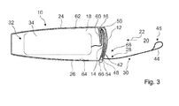
- first closure element 12 and the second closure element 14 are located to each other and are interconnected ( Fig. 3 ).
- the first closure element 12 forms an outer wall of the stowage unit 10 in the stowed state.
- the stowage device comprises a closure unit 68, which is formed by a hook-and-loop fastener unit 28.
- the Velcro closure unit 28 connects the first closure element 12 and the second closure element 14 in the stowed state with each other.
- the Velcro closure unit 28 has a Velcro and hook tape 42.
- other hook-and-loop fastener systems which appear to be useful to a person skilled in the art are also conceivable, in particular mushroom bands or hook and velor bands.
- the stowage device comprises a tab unit 30.
- the tab unit 30 is provided to pull an object 32, in particular the life jacket 34, out of the stowage space 18.
- the tab unit 30 has a band-shaped, bend-soft tension band 44.
- the drawstring 44 is made of a textile fabric. In this context, however, it is also conceivable to use other materials which appear expedient to the person skilled in the art, in particular plastic materials.
- the drawstring 44 has a tab-like handle 46. From the handle 46 from the drawstring 44 runs serpentine or S-shaped on the first closure member 12 and the second closure member 14 along in the storage space 18. In the storage space 18, the drawstring 44 is attached to the life jacket 34.
- a flat recess 48, 50 is respectively arranged on a free edge.
- the drawstring 44 extends in a stowed state.
- the handle 46 When a user pulls on the handle 46, the first closure element 12 and the second closure element 14 are folded away from the storage space 18 from a region of the recesses 48, 50.
- an opening operation of the stowing device takes place.
- the stowage device In the opening operation, the stowage device is brought from the stowed state to the use state.
- the life jacket 34 is pulled out of the storage space 18 during the opening process.
- the stowage device also has a sealing unit 36, which is partially destroyed during the opening process.
- the sealing unit 36 comprises outer wall tabs 52, 54, which are arranged on the second outer wall 26.
- the sealing unit 36 includes fastener tabs 56, 58 which are secured to the first Closing element 12 are arranged.
- the outer wall tabs 52, 54 and the closure element tabs 56, 58 are offset relative to one another.
- a sealing member 66 formed by a seal is guided and sealed by the outer wall tabs 52, 54 and the closure member tabs 56, 58 , An opening of the first closure element 12 is thus possible only by breaking or destroying the sealing element 66.
- the stowage device has a lock element 16, which obstructs passage through the first closure element 12 and the second closure element 14 into the stowage space 18.
- the lock element 16 secures access from the environment 20 to the storage space 18 from unwanted access.
- the lock element 16 releases the access from the environment 20 to the storage space 18.
- the lock element 16, like the first closure element 12, is arranged on the first outer wall 24.
- the lock element 16 is formed flexibly deflectable relative to the first outer wall 24 and the second outer wall 26.
- the lock element 16 is formed as a lock flap.
- the lock element 16 has a wall which is formed from a plastic material.
- first closure element 12, the second closure element 14 and the lock element 16 are each largely formed by a flexible material.
- the first closure element 12, the second closure element 14 and the lock element 16 are each largely formed by a plastic film with a thickness of 3 mm.
- the lock element 16, viewed from the surroundings 20 in a direction 22 of the storage space 18, is arranged behind the first closure element 12 and the second closure element 14.
- the second closure element 14 lies partially against the first closure element 12 and partially against the lock element 16.
- the lock element 16 adjoins the storage space 18 and thus forms a boundary surface 60 of the storage space 18. Furthermore, the lock element 16 forms a stop in the area of the first outer wall 24. Is an elongated object through the Velcro and Hook tape 42 pushed through between the first closure element 12 and the second closure element 14, it abuts against the lock element 16. An intrusion of the article in the storage space 18 is thereby avoided.
Landscapes
- Engineering & Computer Science (AREA)
- Aviation & Aerospace Engineering (AREA)
- Bag Frames (AREA)
- Packaging Of Annular Or Rod-Shaped Articles, Wearing Apparel, Cassettes, Or The Like (AREA)
- Filling Or Discharging Of Gas Storage Vessels (AREA)
- Wind Motors (AREA)
Abstract
Description
- Die Erfindung geht aus von einer Verstauvorrichtung nach dem Oberbegriff des Patentanspruchs 1.
- Es ist bereits eine Verstauvorrichtung, insbesondere eine Schwimmwestenverstauvorrichtung, mit einer Verstaueinheit, die ein erstes Verschlusselement und zumindest ein zweites Verschlusselement aufweist, die dazu vorgesehen sind, einen Verstauraum der Verstaueinheit von einer Umgebung abzugrenzen, bekannt.
- Es liegt der Erfindung insbesondere die Aufgabe zugrunde, ein in der Verstaueinheit verstautes Objekt vor äußeren Einflüssen oder Beschädigungen zu schützen.
- Diese Aufgabe wird durch eine Verstauvorrichtung gemäß dem Patentanspruch 1 gelöst. Weitere vorteilhafte Ausführungen der Erfindung können den Unteransprüchen entnommen werden.
- Die Erfindung geht aus von einer Verstauvorrichtung, insbesondere von einer Schwimmwestenverstauvorrichtung, mit einer Verstaueinheit, die ein erstes Verschlusselement und zumindest ein zweites Verschlusselement aufweist, die dazu vorgesehen sind, einen Verstauraum der Verstaueinheit von einer Umgebung abzugrenzen.
- Es wird vorgeschlagen, dass die Verstauvorrichtung zumindest ein Schleusenelement aufweist, das dazu vorgesehen ist, einen Durchgriff an dem ersten und dem zweiten Verschlusselement vorbei in den Verstauraum zumindest zu behindern, wodurch ein im Verstauraum befindlicher Gegenstand, wie insbesondere eine Schwimmweste, besonders gut vor äußeren Einflüssen oder Beschädigungen geschützt ist. Unter einer "Verstaueinheit" soll in diesem Zusammenhang insbesondere eine Einheit verstanden werden, die dazu vorgesehen ist, zumindest einen Gegenstand zumindest zeitweise zu verstauen und/oder vor äußeren Einflüssen zu schützen. Bevorzugt ist die Verstaueinheit dazu vorgesehen, zum Einlegen des zumindest einen Gegenstands geöffnet und/oder zum Entnehmen des zumindest einen Gegenstands geschlossen zu werden. Unter einem "Verschlusselement" soll in diesem Zusammenhang insbesondere ein von einer Verstauposition in eine Gebrauchsposition bewegbares Element verstanden werden, das dazu vorgesehen ist, den Verstauraum der Verstaueinheit in der Verstauposition von einer Umgebung abzugrenzen und in der Gebrauchsposition zu einer Umgebung hin zu öffnen. Unter einer "Verstauposition" soll in diesem Zusammenhang insbesondere eine Position eines Bauteils verstanden werden, in welcher sich dieses in einem Verstauzustand der Verstauvorrichtung befindet. Unter einer "Gebrauchsposition" soll in diesem Zusammenhang insbesondere eine Position eines Bauteils verstanden werden, in welcher sich dieses in einem Gebrauchszustand der Verstauvorrichtung befindet. Unter einem "Verstauraum" soll in diesem Zusammenhang insbesondere ein Raum verstanden werden, der dazu vorgesehen ist, einen Gegenstand aufzunehmen und von einer Umgebung abzugrenzen. Unter einer "Umgebung" soll in diesem Zusammenhang ein die Verstauvorrichtung umgebender Raum verstanden werden. Unter "abgrenzen" soll in diesem Zusammenhang insbesondere abschirmen und/oder räumlich trennen verstanden werden. Unter einem "Schleusenelement" soll in diesem Zusammenhang insbesondere ein Element verstanden werden, das dazu vorgesehen ist, in einer Verstauposition einen Zugang von einer Umgebung zu einem abgeschlossenen Raum vor einem unerwünschten Zugriff zu sichern. Vorteilhaft ist das Schleusenelement dazu vorgesehen, den Zugang von der Umgebung zu dem abgeschlossenen Raum in einer Gebrauchsposition freizugeben. Besonders bevorzugt ist das Schleusenelement relativ zu anderen, den Raum begrenzenden Wandungen beweglich ausgebildet. Weiterhin vorteilhaft weist das Schleusenelement zumindest eine Wandung auf. Ebenfalls vorteilhaft differiert das Schleusenelement von dem ersten und zweiten Verschlusselement, einem Flausch- und Hakensystem, einem Klebeband und/oder einer Naht. Unter einem "Durchgriff" soll ein vollständiges Durchführen eines insbesondere lang gestreckten Gegenstands und/oder eines Körperteils von der Umgebung in den Verstauraum verstanden werden. Unter "vorgesehen" soll insbesondere speziell ausgelegt und/oder ausgestattet verstanden werden.
- In einer weiteren Ausgestaltung der Erfindung wird vorgeschlagen, dass das Schleusenelement, von der Umgebung in Richtung des Verstauraums betrachtet, hinter dem ersten und dem zweiten Verschlusselement angeordnet ist, wodurch das Schleusenelement vor äußeren Einflüssen oder Beschädigungen vorteilhaft geschützt ist.
- Ferner wird vorgeschlagen, dass das Schleusenelement als Schleusenklappe ausgebildet ist, wodurch das Schleusenelement in einer Gebrauchsposition weggeklappt und ein im Verstauraum angeordneter Gegenstand besonders leicht entfernt werden kann. Unter einer "Schleusenklappe" soll in diesem Zusammenhang insbesondere eine schwenkbar gelagerte und/oder flexibel auslenkbare Klappe verstanden werden, die dazu vorgesehen ist, in einer Verstauposition einen Zugang von einer Umgebung zu einem abgeschlossenen Raum vor einem unerwünschten Zugriff zu sichern.
- Des Weiteren wird vorgeschlagen, dass das erste Verschlusselement von einer ersten Verschlussklappe gebildet ist, wodurch das Verschlusselement in einer Gebrauchsposition weggeklappt und ein im Verstauraum angeordneter Gegenstand besonders leicht entfernt werden kann. Ebenso vorteilhaft ist das zweite Verschlusselement von einer zweiten Verschlussklappe gebildet. Unter einer "Verschlussklappe" soll in diesem Zusammenhang insbesondere ein schwenkbar gelagertes und/oder flexibel auslenkbares Verschlusselement verstanden werden.
- Ein besonders einfaches und zugleich sicheres Verschließen des Verstauraums kann erreicht werden, wenn das zweite Verschlusselement in einem Verstauzustand zumindest teilweise am ersten Verschlusselement und zumindest teilweise am Schleusenelement anliegt. Unter "anliegen" soll in diesem Zusammenhang insbesondere direkt kontaktieren und bevorzugt flächig miteinander verbunden sein verstanden werden. In einer zusätzlichen Ausgestaltung weisen das erste und das zweite Verschlusselement im Wesentlichen deckungsgleiche Querschnitte auf.
- Weiterhin vorteilhaft grenzt das Schleusenelement an den Verstauraum zumindest teilweise an, wodurch eine besonders kompakte Bauweise der Verstauvorrichtung erreicht werden kann. Unter "angrenzen" soll in diesem Zusammenhang insbesondere eine Begrenzungsfläche bilden verstanden werden.
- Ferner wird vorgeschlagen, dass das erste Verschlusselement und das Schleusenelement an einer ersten Außenwandung der Verstaueinheit angeordnet sind, wodurch ein besonders einfacher Öffnungs- und Verschließvorgang der Verstauvorrichtung erreicht werden kann. Unter einer "Außenwandung" soll in diesem Zusammenhang insbesondere eine Wandung verstanden werden, die dazu vorgesehen ist, eine Außenfläche zu bilden, die einer Umgebung zugewandt beziehungsweise von der Verstauvorrichtung abgewandt ist. Bevorzugt bildet die Außenwandung ebenfalls eine Begrenzungsfläche des Verstauraums.
- In einer weiteren Ausgestaltung der Erfindung wird vorgeschlagen, dass das zweite Verschlusselement an einer zweiten Außenwandung angeordnet ist, die der ersten Außenwandung gegenüberliegend angeordnet ist, wodurch ein besonders sicherer Verschluss des Verstauraums erreicht werden kann. Unter "gegenüberliegend" soll in diesem Zusammenhang insbesondere verstanden werden, dass die zweite Außenwandung eine zweite Außenfläche bildet, die einer ersten Außenfläche der ersten Außenwandung abgewandt ist. Insbesondere sind die erste Außenwandung und die zweite Außenwandung zum Großteil vom Verstauraum getrennt. Unter "zum Großteil" soll in diesem Zusammenhang insbesondere um mehr als 50%, bevorzugt um mehr als 80% und besonders bevorzugt um mehr als 95% verstanden werden.
- Des Weiteren wird vorgeschlagen, dass das erste Verschlusselement, das zweite Verschlusselement und das Schleusenelement jeweils zumindest zum Großteil von einem biegeweichen Material gebildet sind, wodurch zusätzliche, für eine Bewegung benötigte Bauteile, wie insbesondere Gelenke und/oder Scharniere, vermieden werden können. Zusätzlich wird vorgeschlagen, dass das erste Verschlusselement, das zweite Verschlusselement und/oder das Schleusenelement mit einem Textilmaterial, wie insbesondere einem Stoffbezug, überzogen ist.
- Gewicht und Produktionskosten können eingespart werden, wenn das erste Verschlusselement, das zweite Verschlusselement und das Schleusenelement jeweils zumindest zum Großteil von einer Kunststofffolie gebildet sind. Unter einer "Kunststofffolie" soll in diesem Zusammenhang insbesondere ein aus Kunststoff bestehendes, biegeweiches, flächiges Objekt mit einer Dicke von weniger als 8 mm, bevorzugt von weniger als 5 mm und besonders bevorzugt von weniger als 3 mm verstanden werden.
- Eine besonders einfache Verschlusssicherung des Verstauraums kann erreicht werden, wenn die Verstauvorrichtung eine Verschlusseinheit umfasst, die dazu vorgesehen ist, das erste und zweite Verschlusselement in einem Verstauzustand miteinander zu verbinden. Besonders vorteilhaft ist die Verschlusseinheit von einer "Klettverschlusseinheit" gebildet. Unter einer "Verschlusseinheit" soll in diesem Zusammenhang insbesondere eine Einheit verstanden werden, die dazu vorgesehen ist, zumindest zwei Bauteile lösbar miteinander zu verbinden. Unter einer "Klettverschlusseinheit" soll insbesondere eine Einheit verstanden werden, die zumindest einen Teil eines Klettverschlusses aufweist, wie beispielsweise ein Hakenband, ein Flauschband, ein Pilzband und/oder ein Veloursband.
- Ferner wird vorgeschlagen, dass die Verstauvorrichtung eine Lascheneinheit umfasst, die dazu vorgesehen ist, einen Gegenstand, insbesondere eine Schwimmweste, aus dem Verstauraum zu ziehen, wodurch ein besonders schnelles Leeren der Verstauvorrichtung erreicht werden kann. Unter einer "Lascheneinheit" soll in diesem Zusammenhang insbesondere eine Einheit verstanden werden, die ein biegeweiches, bandartiges Element umfasst, wobei das Element zum Öffnen der Verstauvorrichtung und/oder zum Herausziehen eines Gegenstands aus dem Verstauraum vorgesehen ist.
- Ein Öffnungsvorgang der Verstauvorrichtung kann angezeigt werden, wenn die Verstauvorrichtung eine Versiegelungseinheit aufweist, die dazu vorgesehen ist, bei dem Öffnungsvorgang zumindest teilweise zerstört zu werden. Unter einer "Versiegelungseinheit" soll in diesem Zusammenhang insbesondere eine Einheit verstanden werden, die zumindest ein plombenartiges Versiegelungselement umfasst. Unter einem "Öffnungsvorgang" soll in diesem Zusammenhang insbesondere ein Vorgang verstanden werden, bei welchem die Verstauvorrichtung von dem Verstauzustand in den Gebrauchszustand gebracht wird.
- Weitere Vorteile ergeben sich aus der folgenden Zeichnungsbeschreibung. In den Zeichnungen ist ein Ausführungsbeispiel der Erfindung dargestellt. Die Beschreibung und die Ansprüche enthalten zahlreiche Merkmale in Kombination. Der Fachmann wird die Merkmale zweckmäßigerweise auch einzeln betrachten und zu sinnvollen weiteren Kombinationen zusammenfassen.
- Es zeigen:
- Fig. 1
- eine schematische Vorderansicht einer erfindungsgemäßen Verstauvorrichtung,
- Fig. 2
- eine schematische Schnittdarstellung der Verstauvorrichtung aus
Figur 1 in einem Gebrauchszustand und - Fig. 3
- eine schematische Schnittdarstellung der Verstauvorrichtung aus
Figur 1 in einem Verstauzustand. - In
Figur 1 ist schematisch eine erfindungsgemäße Verstauvorrichtung gezeigt, die als Schwimmwestenverstauvorrichtung ausgebildet ist. Die Verstauvorrichtung weist zum Verstauen eines Gegenstands 32, der von einer Schwimmweste 34 gebildet ist, eine Verstaueinheit 10 auf. Die Verstaueinheit 10 umfasst eine erste Außenwandung 24 und eine zweite Außenwandung 26. Die erste Außenwandung 24 und die zweite Außenwandung 26 sind jeweils von einer biegeweichen Kunststofffolie gebildet. Die erste Außenwandung 24 ist in einem Randbereich 38 an drei Kanten mit der zweiten Außenwandung 26 vernäht. Es ist in diesem Zusammenhang jedoch auch denkbar, die erste Außenwandung 24 auf eine andere, dem Fachmann als sinnvoll erscheinende Weise mit der zweiten Außenwandung 26 zu verbinden. Durch eine Wölbung der ersten Außenwandung 24 und der zweiten Außenwandung 26 spannen diese einen Verstauraum 18 auf, der zur Aufnahme der Schwimmweste 34 vorgesehen ist. Die erste Außenwandung 24 und die zweite Außenwandung 26 bilden eine Außenfläche, die einer Umgebung 20 der Verstauvorrichtung zugewandt beziehungsweise von der Verstauvorrichtung abgewandt ist. Die erste Außenwandung 24 und die zweite Außenwandung 26 bilden jeweils eine Begrenzungsfläche 62, 64 des Verstauraums 18. Der Verstauraum 18 weist im Gebrauchszustand eine Öffnung 40 auf. Durch die Öffnung 40 lässt sich im Gebrauchszustand während einer Fertigung die Schwimmweste 34 in den Verstauraum 18 einlegen. Bei Bedarf lässt sich die Schwimmweste 34 im Gebrauchszustand aus dem Verstauraum 18 entfernen. - Für eine sichere Lagerung der Schwimmweste 34 wird die Verstauvorrichtung in einen Verstauzustand gebracht. Dazu weist die Verstaueinheit 10 ein erstes Verschlusselement 12 und ein zweites Verschlusselement 14 auf. Das erste Verschlusselement 12 und das zweite Verschlusselement 14 verschließen die Öffnung 40 im Verstauzustand. Ein Einlegen oder Entnehmen des Gegenstands 32 in den Verstauraum 18 im Verstauzustand wird vermieden. Der Verstauraum 18 der Verstaueinheit 10 ist somit im Verstauzustand durch das erste Verschlusselement 12 und das zweite Verschlusselement 14 von der Umgebung 20 abgegrenzt.
- Das erste Verschlusselement 12 ist von einer ersten biegeweichen Verschlussklappe gebildet. Das zweite Verschlusselement 14 ist von einer zweiten biegeweichen Verschlussklappe gebildet. Dabei sind das erste Verschlusselement 12 und das zweite Verschlusselement 14 jeweils flexibel auslenkbar. Es ist in diesem Zusammenhang jedoch auch denkbar, dass ein Fachmann zusätzlich Gelenke, wie beispielsweise Scharniere, vorsieht, welche das erste Verschlusselement 12 und das zweite Verschlusselement 14 relativ zur ersten Außenwandung 24 und zur zweiten Außenwandung 26 schwenkbar lagern. Das erste Verschlusselement 12 ist an der ersten Außenwandung 24 angeordnet. Das zweite Verschlusselement 14 ist an der zweiten Außenwandung 26 angeordnet, die der ersten Außenwandung 24 gegenüberliegend angeordnet ist. Das erste Verschlusselement 12 und das zweite Verschlusselement 14 weisen im Wesentlichen deckungsgleiche Querschnitte auf.
- Im Gebrauchszustand erstrecken sich das erste Verschlusselement 12 und das zweite Verschlusselement 14 jeweils im Wesentlichen parallel zu der ersten Au βenwandung 24 und der zweiten Außenwandung 26 (
Fig. 2 ). Im Verstauzustand erstrecken sich das erste Verschlusselement 12 und das zweite Verschlusselement 14 jeweils im Wesentlichen senkrecht zu der ersten Au βenwandung 24 und der zweiten Au ßenwandung 26. Im Verstauzustand liegen das erste Verschlusselement 12 und das zweite Verschlusselement 14 aneinander an und sind miteinander verbunden (Fig. 3 ). Das erste Verschlusselement 12 bildet im Verstauzustand eine Außenwandung der Verstaueinheit 10. - Die Verstauvorrichtung umfasst eine Verschlusseinheit 68, die von einer Klettverschlusseinheit 28 gebildet ist. Die Klettverschlusseinheit 28 verbindet das erste Verschlusselement 12 und das zweite Verschlusselement 14 im Verstauzustand miteinander. Die Klettverschlusseinheit 28 weist ein Flausch- und Hakenband 42 auf. Es sind in diesem Zusammenhang jedoch auch andere, dem Fachmann als sinnvoll erscheinende Klettverschlusssysteme denkbar, wie insbesondere Pilzbänder oder Haken- und Veloursbänder.
- Zum Herausnehmen der Schwimmweste 34 umfasst die Verstauvorrichtung eine Lascheneinheit 30. Die Lascheneinheit 30 ist dazu vorgesehen, einen Gegenstand 32, wie insbesondere die Schwimmweste 34, aus dem Verstauraum 18 zu ziehen. Dazu weist die Lascheneinheit 30 ein bandförmiges, biegeweiches Zugband 44 auf. Das Zugband 44 besteht aus einem Textilgewebe. Es ist in diesem Zusammenhang jedoch auch denkbar, andere, dem Fachmann als sinnvoll erscheinende Materialien zu verwenden, wie insbesondere Kunststoffmaterialien. An einem freien Ende weist das Zugband 44 einen laschenartigen Griff 46 auf. Vom Griff 46 aus verläuft das Zugband 44 schlangenförmig beziehungsweise S-förmig am ersten Verschlusselement 12 und am zweiten Verschlusselement 14 entlang in den Verstauraum 18. Im Verstauraum 18 ist das Zugband 44 an der Schwimmweste 34 befestigt. Am ersten Verschlusselement 12 und am zweiten Verschlusselement 14 ist jeweils an einer freien Kante eine flache Aussparung 48, 50 angeordnet. In den Aussparungen 48, 50 verläuft in einem Verstauzustand das Zugband 44. Zieht ein Benutzer an dem Griff 46, werden das erste Verschlusselement 12 und das zweite Verschlusselement 14 von einem Bereich der Aussparungen 48, 50 aus vom Verstauraum 18 weggeklappt. Somit findet durch ein Ziehen am Griff 46 ein Öffnungsvorgang der Verstauvorrichtung statt. Beim Öffnungsvorgang wird die Verstauvorrichtung von dem Verstauzustand in den Gebrauchszustand gebracht. Die Schwimmweste 34 wird während des Öffnungsvorgangs aus dem Verstauraum 18 herausgezogen.
- Die Verstauvorrichtung weist zudem eine Versiegelungseinheit 36 auf, die bei dem Öffnungsvorgang teilweise zerstört wird. Dazu umfasst die Versiegelungseinheit 36 Außenwandungslaschen 52, 54, die an der zweiten Außenwandung 26 angeordnet sind. Ferner beinhaltet die Versiegelungseinheit 36 Verschlusselementlaschen 56, 58, die am ersten Verschlusselement 12 angeordnet sind. Die Au ßenwandungslaschen 52, 54 und die Verschlusselementlaschen 56, 58 sind versetzt zueinander angeordnet. Wird das erste Verschlusselement 12 geschlossen, kommen die Außenwandungslaschen 52, 54 in Deckung mit den Verschlusselementlaschen 56, 58. Nun wird ein Versiegelungselement 66, das von einer Plombe gebildet ist, durch die Außenwandungslaschen 52, 54 und die Verschlusselementlaschen 56, 58 geführt und versiegelt. Ein Öffnen des ersten Verschlusselements 12 ist somit nur durch ein Brechen beziehungsweise ein Zerstören des Versiegelungselements 66 möglich.
- Die Verstauvorrichtung weist ein Schleusenelement 16 auf, das einen Durchgriff an dem ersten Verschlusselement 12 und dem zweiten Verschlusselement 14 vorbei in den Verstauraum 18 behindert. Somit sichert das Schleusenelement 16 in einer Verstauposition einen Zugang von der Umgebung 20 zum Verstauraum 18 vor einem unerwünschten Zugriff. In einer Gebrauchsposition gibt das Schleusenelement 16 den Zugang von der Umgebung 20 zu dem Verstauraum 18 frei. Das Schleusenelement 16 ist, wie auch das erste Verschlusselement 12, an der ersten Außenwandung 24 angeordnet. Dazu ist das Schleusenelement 16 relativ zur ersten Außenwandung 24 und zur zweiten Außenwandung 26 flexibel auslenkbar ausgebildet. Somit ist das Schleusenelement 16 als Schleusenklappe ausgebildet. Das Schleusenelement 16 weist eine Wandung auf, die aus einem Kunststoffmaterial gebildet ist.
- Somit sind das erste Verschlusselement 12, das zweite Verschlusselement 14 und das Schleusenelement 16 jeweils zum Großteil von einem biegeweichen Material gebildet. Das erste Verschlusselement 12, das zweite Verschlusselement 14 und das Schleusenelement 16 sind dabei jeweils zum Großteil von einer Kunststofffolie mit einer Dicke von 3 mm gebildet. Das Schleusenelement 16 ist, von der Umgebung 20 in einer Richtung 22 des Verstauraums 18 betrachtet, hinter dem ersten Verschlusselement 12 und dem zweiten Verschlusselement 14 angeordnet.
- Das zweite Verschlusselement 14 liegt im Verstauzustand teilweise am ersten Verschlusselement 12 und teilweise am Schleusenelement 16 an. Das Schleusenelement 16 grenzt an den Verstauraum 18 an und bildet somit eine Begrenzungsfläche 60 des Verstauraums 18. Ferner bildet das Schleusenelement 16 im Bereich der ersten Außenwandung 24 einen Anschlag. Wird ein lang gestreckter Gegenstand durch das Flausch- und Hakenband 42 zwischen dem ersten Verschlusselement 12 und dem zweiten Verschlusselement 14 durchgeschoben, stößt er gegen das Schleusenelement 16. Ein Eindringen des Gegenstands in den Verstauraum 18 ist dadurch vermieden.
-
10 Verstaueinheit 12 Verschlusselement 14 Verschlusselement 16 Schleusenelement 18 Verstauraum 20 Umgebung 22 Richtung 24 Außenwandung 26 Außenwandung 28 Klettverschlusseinheit 30 Lascheneinheit 32 Gegenstand 34 Schwimmweste 36 Versiegelungseinheit 38 Randbereich 40 Öffnung 42 Flausch- und Hakenband 44 Zugband 46 Griff 48 Aussparung 50 Aussparung 52 Außenwandungslasche 54 Außenwandungslasche 56 Verschlusselementlasche 58 Verschlusselementlasche 60 Begrenzungsfläche 62 Begrenzungsfläche 64 Begrenzungsfläche 66 Versiegelungselement 68 Verschlusseinheit
Claims (16)
- Verstauvorrichtung, insbesondere Schwimmwestenverstauvorrichtung, mit einer Verstaueinheit (10), die ein erstes Verschlusselement (12) und zumindest ein zweites Verschlusselement (14) aufweist, die dazu vorgesehen sind, einen Verstauraum (18) der Verstaueinheit (10) von einer Umgebung (20) abzugrenzen, gekennzeichnet durch zumindest ein Schleusenelement (16), das dazu vorgesehen ist, einen Durchgriff an dem ersten Verschlusselement (12) und dem zweiten Verschlusselement (14) vorbei in den Verstauraum (18) zumindest zu behindern.
- Verstauvorrichtung nach Anspruch 1, dadurch gekennzeichnet, dass das Schleusenelement (16), von der Umgebung (20) in einer Richtung (22) des Verstauraums (18) betrachtet, hinter dem ersten Verschlusselement (12) und dem zweiten Verschlusselement (14) angeordnet ist.
- Verstauvorrichtung nach Anspruch 1 oder 2, dadurch gekennzeichnet, dass das Schleusenelement (16) als Schleusenklappe ausgebildet ist.
- Verstauvorrichtung nach einem der vorhergehenden Ansprüche, dadurch gekennzeichnet, dass das erste Verschlusselement (12) von einer ersten Verschlussklappe gebildet ist.
- Verstauvorrichtung nach einem der vorhergehenden Ansprüche, dadurch gekennzeichnet, dass das zweite Verschlusselement (14) von einer zweiten Verschlussklappe gebildet ist.
- Verstauvorrichtung nach einem der vorhergehenden Ansprüche, dadurch gekennzeichnet, dass das zweite Verschlusselement (14) in einem Verstauzustand zumindest teilweise am ersten Verschlusselement (12) und zumindest teilweise am Schleusenelement (16) anliegt.
- Verstauvorrichtung nach einem der vorhergehenden Ansprüche, dadurch gekennzeichnet, dass das Schleusenelement (16) an den Verstauraum (18) zumindest teilweise angrenzt.
- Verstauvorrichtung nach einem der vorhergehenden Ansprüche, dadurch gekennzeichnet, dass das erste Verschlusselement (12) und das Schleusenelement (16) an einer ersten Außenwandung (24) der Verstaueinheit (10) angeordnet sind.
- Verstauvorrichtung nach Anspruch 8, dadurch gekennzeichnet, dass das zweite Verschlusselement (14) an einer zweiten Außenwandung (26) angeordnet ist, die der ersten Au βenwandung (24) gegenüberliegend angeordnet ist.
- Verstauvorrichtung nach einem der vorhergehenden Ansprüche, dadurch gekennzeichnet, dass das erste Verschlusselement (12), das zweite Verschlusselement (14) und das Schleusenelement (16) jeweils zumindest zum Großteil von einem biegeweichen Material gebildet sind.
- Verstauvorrichtung nach Anspruch 10, dadurch gekennzeichnet, dass das erste Verschlusselement (12), das zweite Verschlusselement (14) und das Schleusenelement (16) jeweils zumindest zum Großteil von einer Kunststofffolie gebildet sind.
- Verstauvorrichtung nach einem der vorhergehenden Ansprüche, gekennzeichnet durch eine Verschlusseinheit (68), die dazu vorgesehen ist, das erste Verschlusselement (12) und zweite Verschlusselement (14) in einem Verstauzustand miteinander zu verbinden.
- Verstauvorrichtung nach Anspruch 12, dadurch gekennzeichnet, dass die Verschlusseinheit (68) von einer Klettverschlusseinheit (28) gebildet ist.
- Verstauvorrichtung nach einem der vorhergehenden Ansprüche, gekennzeichnet durch eine Lascheneinheit (30), die dazu vorgesehen ist, einen Gegenstand (32), insbesondere eine Schwimmweste (34), aus dem Verstauraum (18) zu ziehen.
- Verstauvorrichtung nach einem der vorhergehenden Ansprüche, gekennzeichnet durch eine Versiegelungseinheit (36), die dazu vorgesehen ist, bei einem Öffnungsvorgang zumindest teilweise zerstört zu werden.
- System mit einer Verstauvorrichtung nach einem der vorhergehenden Ansprüche und mit einer Schwimmweste (34).
Applications Claiming Priority (1)
| Application Number | Priority Date | Filing Date | Title |
|---|---|---|---|
| DE102012004154A DE102012004154A1 (de) | 2012-03-05 | 2012-03-05 | Verstauvorrichtung, insbesondere Schwimmwestenverstauvorrichtung |
Publications (3)
| Publication Number | Publication Date |
|---|---|
| EP2636332A2 true EP2636332A2 (de) | 2013-09-11 |
| EP2636332A3 EP2636332A3 (de) | 2017-04-12 |
| EP2636332B1 EP2636332B1 (de) | 2019-10-09 |
Family
ID=47900638
Family Applications (1)
| Application Number | Title | Priority Date | Filing Date |
|---|---|---|---|
| EP13157865.0A Active EP2636332B1 (de) | 2012-03-05 | 2013-03-05 | Verstauvorrichtung, insbesondere Schwimmwestenverstauvorrichtung |
Country Status (2)
| Country | Link |
|---|---|
| EP (1) | EP2636332B1 (de) |
| DE (1) | DE102012004154A1 (de) |
Cited By (4)
| Publication number | Priority date | Publication date | Assignee | Title |
|---|---|---|---|---|
| WO2015145121A1 (en) * | 2014-03-26 | 2015-10-01 | Servecorp Limited | Tamper detectable container |
| WO2017121895A1 (en) * | 2016-01-15 | 2017-07-20 | Servecorp Limited | Sealable life vest stowage device |
| FR3058124A1 (fr) * | 2016-10-31 | 2018-05-04 | Zodiac Seats France | Pochette inviolable de gilet de sauvetage |
| CN110667855A (zh) * | 2019-10-15 | 2020-01-10 | 湖北航宇嘉泰飞机设备有限公司 | 一种防篡改救生衣盒 |
Families Citing this family (3)
| Publication number | Priority date | Publication date | Assignee | Title |
|---|---|---|---|---|
| US10494099B2 (en) * | 2017-01-31 | 2019-12-03 | B/E Aerospace, Inc. | Aircraft life vest stowage pouch |
| US10668998B2 (en) * | 2018-06-21 | 2020-06-02 | Courtney Tassie | Life vest pouch |
| US11453500B2 (en) * | 2019-10-10 | 2022-09-27 | Recaro Aircraft Seating Gmbh & Co. Kg | Life vest device |
Family Cites Families (8)
| Publication number | Priority date | Publication date | Assignee | Title |
|---|---|---|---|---|
| GB1367341A (en) * | 1971-03-11 | 1974-09-18 | Beaufort Air Sea Equipment Ltd | Life saving appliances |
| US4297758A (en) * | 1980-01-28 | 1981-11-03 | Switlik Parachute Company, Inc. | Life preserver of the encapsulated type |
| JP3756064B2 (ja) * | 2000-10-10 | 2006-03-15 | 株式会社ケイセブン | 救命具 |
| DE10143438A1 (de) * | 2001-09-05 | 2003-03-27 | Recaro Aircraft Seating Gmbh | Schwimmwestentasche |
| US6902453B2 (en) * | 2002-05-15 | 2005-06-07 | Switlik Parachute Company, Inc. | High security opening apparatus for hermetically sealed containers |
| DE102007030565A1 (de) * | 2007-06-30 | 2009-01-02 | Recaro Aircraft Seating Gmbh & Co. Kg | Sitzvorrichtung mit Fahrzeugbehältervorrichtung |
| DE202010005294U1 (de) * | 2010-04-23 | 2011-08-23 | Günther Steinecker | Schwimmwestenverpackung |
| GB2492813B (en) * | 2011-07-13 | 2014-07-16 | Servecorp Ltd | Life vest stowage device |
-
2012
- 2012-03-05 DE DE102012004154A patent/DE102012004154A1/de not_active Withdrawn
-
2013
- 2013-03-05 EP EP13157865.0A patent/EP2636332B1/de active Active
Non-Patent Citations (1)
| Title |
|---|
| None |
Cited By (6)
| Publication number | Priority date | Publication date | Assignee | Title |
|---|---|---|---|---|
| WO2015145121A1 (en) * | 2014-03-26 | 2015-10-01 | Servecorp Limited | Tamper detectable container |
| TWI658436B (zh) * | 2014-03-26 | 2019-05-01 | 英商瑟維寇普有限公司 | 可檢測破壞之容器 |
| WO2017121895A1 (en) * | 2016-01-15 | 2017-07-20 | Servecorp Limited | Sealable life vest stowage device |
| US11352141B2 (en) | 2016-01-15 | 2022-06-07 | Servecorp Limited | Sealable life vest stowage device |
| FR3058124A1 (fr) * | 2016-10-31 | 2018-05-04 | Zodiac Seats France | Pochette inviolable de gilet de sauvetage |
| CN110667855A (zh) * | 2019-10-15 | 2020-01-10 | 湖北航宇嘉泰飞机设备有限公司 | 一种防篡改救生衣盒 |
Also Published As
| Publication number | Publication date |
|---|---|
| DE102012004154A1 (de) | 2013-09-05 |
| EP2636332B1 (de) | 2019-10-09 |
| EP2636332A3 (de) | 2017-04-12 |
Similar Documents
| Publication | Publication Date | Title |
|---|---|---|
| EP2636332B1 (de) | Verstauvorrichtung, insbesondere Schwimmwestenverstauvorrichtung | |
| DE112012004871B4 (de) | Reissverschluss | |
| EP0550815B1 (de) | Handschliessplombe | |
| DE69732438T2 (de) | Verriegelungsvorrichtung | |
| DE60204357T2 (de) | Etui für Handschellen | |
| DE60304443T2 (de) | Verschlussvorrichtung | |
| DE102016004956A1 (de) | Aufbewahrungsvorrichtung zum sicheren Aufbewahren von Gegenständen | |
| EP1857375B1 (de) | Behälterverschluss mit Verschlussplombe für Kunststoffbehälter | |
| DE60016462T2 (de) | Verschliessbarer behälter | |
| DE102008018559A1 (de) | Handschuhkasten für ein Kraftfahrzeug | |
| DE60006635T2 (de) | Gerät zum Ausstossen des Inhaltes einer Tasche im Falle eines Diebstahles | |
| EP3698664B1 (de) | Handschuh | |
| DE3229504C2 (de) | Packhüllen-Verschlußvorrichtung | |
| DE3119363A1 (de) | Vorrichtung zur befestigung eines klapp- oder faltbaren verdeckes an einem festen aufbau | |
| DE29820856U1 (de) | Verpackungssystem mit nachträglich aufsetzbarem Deckelaufsatz | |
| DE9402589U1 (de) | Überzug für Frachtcontainer | |
| DE10323119A1 (de) | Koffer | |
| EP2798972A1 (de) | Taschenanordnung | |
| DE202010005294U1 (de) | Schwimmwestenverpackung | |
| AT521848B1 (de) | Tragetasche | |
| DE102011110730A1 (de) | Ladesack für eine Laderaumvergrößerungsvorrichtung eines Kraftfahrzeugs | |
| EP1535529B1 (de) | Kombipackung | |
| DE19548111B4 (de) | Vorrichtung zur Verriegelung und Sicherung | |
| DE2017908A1 (de) | Verfahren und Vorrichtung zur Handhabung von Motorfahrzeug-Schlüsseln | |
| DE202023104710U1 (de) | Stechschutzbekleidung, insbesondere Stechschutzhandschuh |
Legal Events
| Date | Code | Title | Description |
|---|---|---|---|
| PUAI | Public reference made under article 153(3) epc to a published international application that has entered the european phase |
Free format text: ORIGINAL CODE: 0009012 |
|
| AK | Designated contracting states |
Kind code of ref document: A2 Designated state(s): AL AT BE BG CH CY CZ DE DK EE ES FI FR GB GR HR HU IE IS IT LI LT LU LV MC MK MT NL NO PL PT RO RS SE SI SK SM TR |
|
| AX | Request for extension of the european patent |
Extension state: BA ME |
|
| PUAL | Search report despatched |
Free format text: ORIGINAL CODE: 0009013 |
|
| AK | Designated contracting states |
Kind code of ref document: A3 Designated state(s): AL AT BE BG CH CY CZ DE DK EE ES FI FR GB GR HR HU IE IS IT LI LT LU LV MC MK MT NL NO PL PT RO RS SE SI SK SM TR |
|
| AX | Request for extension of the european patent |
Extension state: BA ME |
|
| RIC1 | Information provided on ipc code assigned before grant |
Ipc: B63C 9/23 20060101ALI20170306BHEP Ipc: A45C 13/10 20060101AFI20170306BHEP Ipc: B64D 11/06 20060101ALI20170306BHEP |
|
| STAA | Information on the status of an ep patent application or granted ep patent |
Free format text: STATUS: REQUEST FOR EXAMINATION WAS MADE |
|
| 17P | Request for examination filed |
Effective date: 20171006 |
|
| RBV | Designated contracting states (corrected) |
Designated state(s): AL AT BE BG CH CY CZ DE DK EE ES FI FR GB GR HR HU IE IS IT LI LT LU LV MC MK MT NL NO PL PT RO RS SE SI SK SM TR |
|
| RIC1 | Information provided on ipc code assigned before grant |
Ipc: B64D 11/06 20060101ALI20171207BHEP Ipc: B63C 9/23 20060101ALN20171207BHEP Ipc: B64D 25/18 20060101ALN20171207BHEP Ipc: A45C 13/10 20060101AFI20171207BHEP |
|
| STAA | Information on the status of an ep patent application or granted ep patent |
Free format text: STATUS: EXAMINATION IS IN PROGRESS |
|
| 17Q | First examination report despatched |
Effective date: 20180315 |
|
| REG | Reference to a national code |
Ref country code: DE Ref legal event code: R079 Ref document number: 502013013708 Country of ref document: DE Free format text: PREVIOUS MAIN CLASS: A45C0011000000 Ipc: A45C0013100000 |
|
| GRAP | Despatch of communication of intention to grant a patent |
Free format text: ORIGINAL CODE: EPIDOSNIGR1 |
|
| STAA | Information on the status of an ep patent application or granted ep patent |
Free format text: STATUS: GRANT OF PATENT IS INTENDED |
|
| RIC1 | Information provided on ipc code assigned before grant |
Ipc: A45C 13/10 20060101AFI20190402BHEP Ipc: B64D 25/18 20060101ALN20190402BHEP Ipc: B63C 9/23 20060101ALN20190402BHEP Ipc: B64D 11/06 20060101ALI20190402BHEP |
|
| INTG | Intention to grant announced |
Effective date: 20190426 |
|
| GRAS | Grant fee paid |
Free format text: ORIGINAL CODE: EPIDOSNIGR3 |
|
| GRAA | (expected) grant |
Free format text: ORIGINAL CODE: 0009210 |
|
| STAA | Information on the status of an ep patent application or granted ep patent |
Free format text: STATUS: THE PATENT HAS BEEN GRANTED |
|
| AK | Designated contracting states |
Kind code of ref document: B1 Designated state(s): AL AT BE BG CH CY CZ DE DK EE ES FI FR GB GR HR HU IE IS IT LI LT LU LV MC MK MT NL NO PL PT RO RS SE SI SK SM TR |
|
| REG | Reference to a national code |
Ref country code: GB Ref legal event code: FG4D Free format text: NOT ENGLISH |
|
| REG | Reference to a national code |
Ref country code: CH Ref legal event code: EP |
|
| REG | Reference to a national code |
Ref country code: IE Ref legal event code: FG4D Free format text: LANGUAGE OF EP DOCUMENT: GERMAN |
|
| REG | Reference to a national code |
Ref country code: DE Ref legal event code: R096 Ref document number: 502013013708 Country of ref document: DE |
|
| REG | Reference to a national code |
Ref country code: AT Ref legal event code: REF Ref document number: 1187767 Country of ref document: AT Kind code of ref document: T Effective date: 20191115 |
|
| REG | Reference to a national code |
Ref country code: NL Ref legal event code: MP Effective date: 20191009 |
|
| REG | Reference to a national code |
Ref country code: LT Ref legal event code: MG4D |
|
| PG25 | Lapsed in a contracting state [announced via postgrant information from national office to epo] |
Ref country code: PL Free format text: LAPSE BECAUSE OF FAILURE TO SUBMIT A TRANSLATION OF THE DESCRIPTION OR TO PAY THE FEE WITHIN THE PRESCRIBED TIME-LIMIT Effective date: 20191009 Ref country code: NO Free format text: LAPSE BECAUSE OF FAILURE TO SUBMIT A TRANSLATION OF THE DESCRIPTION OR TO PAY THE FEE WITHIN THE PRESCRIBED TIME-LIMIT Effective date: 20200109 Ref country code: PT Free format text: LAPSE BECAUSE OF FAILURE TO SUBMIT A TRANSLATION OF THE DESCRIPTION OR TO PAY THE FEE WITHIN THE PRESCRIBED TIME-LIMIT Effective date: 20200210 Ref country code: ES Free format text: LAPSE BECAUSE OF FAILURE TO SUBMIT A TRANSLATION OF THE DESCRIPTION OR TO PAY THE FEE WITHIN THE PRESCRIBED TIME-LIMIT Effective date: 20191009 Ref country code: NL Free format text: LAPSE BECAUSE OF FAILURE TO SUBMIT A TRANSLATION OF THE DESCRIPTION OR TO PAY THE FEE WITHIN THE PRESCRIBED TIME-LIMIT Effective date: 20191009 Ref country code: LT Free format text: LAPSE BECAUSE OF FAILURE TO SUBMIT A TRANSLATION OF THE DESCRIPTION OR TO PAY THE FEE WITHIN THE PRESCRIBED TIME-LIMIT Effective date: 20191009 Ref country code: LV Free format text: LAPSE BECAUSE OF FAILURE TO SUBMIT A TRANSLATION OF THE DESCRIPTION OR TO PAY THE FEE WITHIN THE PRESCRIBED TIME-LIMIT Effective date: 20191009 Ref country code: SE Free format text: LAPSE BECAUSE OF FAILURE TO SUBMIT A TRANSLATION OF THE DESCRIPTION OR TO PAY THE FEE WITHIN THE PRESCRIBED TIME-LIMIT Effective date: 20191009 Ref country code: BG Free format text: LAPSE BECAUSE OF FAILURE TO SUBMIT A TRANSLATION OF THE DESCRIPTION OR TO PAY THE FEE WITHIN THE PRESCRIBED TIME-LIMIT Effective date: 20200109 Ref country code: FI Free format text: LAPSE BECAUSE OF FAILURE TO SUBMIT A TRANSLATION OF THE DESCRIPTION OR TO PAY THE FEE WITHIN THE PRESCRIBED TIME-LIMIT Effective date: 20191009 |
|
| PG25 | Lapsed in a contracting state [announced via postgrant information from national office to epo] |
Ref country code: RS Free format text: LAPSE BECAUSE OF FAILURE TO SUBMIT A TRANSLATION OF THE DESCRIPTION OR TO PAY THE FEE WITHIN THE PRESCRIBED TIME-LIMIT Effective date: 20191009 Ref country code: IS Free format text: LAPSE BECAUSE OF FAILURE TO SUBMIT A TRANSLATION OF THE DESCRIPTION OR TO PAY THE FEE WITHIN THE PRESCRIBED TIME-LIMIT Effective date: 20200224 Ref country code: HR Free format text: LAPSE BECAUSE OF FAILURE TO SUBMIT A TRANSLATION OF THE DESCRIPTION OR TO PAY THE FEE WITHIN THE PRESCRIBED TIME-LIMIT Effective date: 20191009 |
|
| PG25 | Lapsed in a contracting state [announced via postgrant information from national office to epo] |
Ref country code: AL Free format text: LAPSE BECAUSE OF FAILURE TO SUBMIT A TRANSLATION OF THE DESCRIPTION OR TO PAY THE FEE WITHIN THE PRESCRIBED TIME-LIMIT Effective date: 20191009 |
|
| REG | Reference to a national code |
Ref country code: DE Ref legal event code: R097 Ref document number: 502013013708 Country of ref document: DE |
|
| PG2D | Information on lapse in contracting state deleted |
Ref country code: IS |
|
| PG25 | Lapsed in a contracting state [announced via postgrant information from national office to epo] |
Ref country code: EE Free format text: LAPSE BECAUSE OF FAILURE TO SUBMIT A TRANSLATION OF THE DESCRIPTION OR TO PAY THE FEE WITHIN THE PRESCRIBED TIME-LIMIT Effective date: 20191009 Ref country code: DK Free format text: LAPSE BECAUSE OF FAILURE TO SUBMIT A TRANSLATION OF THE DESCRIPTION OR TO PAY THE FEE WITHIN THE PRESCRIBED TIME-LIMIT Effective date: 20191009 Ref country code: CZ Free format text: LAPSE BECAUSE OF FAILURE TO SUBMIT A TRANSLATION OF THE DESCRIPTION OR TO PAY THE FEE WITHIN THE PRESCRIBED TIME-LIMIT Effective date: 20191009 Ref country code: RO Free format text: LAPSE BECAUSE OF FAILURE TO SUBMIT A TRANSLATION OF THE DESCRIPTION OR TO PAY THE FEE WITHIN THE PRESCRIBED TIME-LIMIT Effective date: 20191009 Ref country code: IS Free format text: LAPSE BECAUSE OF FAILURE TO SUBMIT A TRANSLATION OF THE DESCRIPTION OR TO PAY THE FEE WITHIN THE PRESCRIBED TIME-LIMIT Effective date: 20200209 |
|
| PLBE | No opposition filed within time limit |
Free format text: ORIGINAL CODE: 0009261 |
|
| STAA | Information on the status of an ep patent application or granted ep patent |
Free format text: STATUS: NO OPPOSITION FILED WITHIN TIME LIMIT |
|
| PG25 | Lapsed in a contracting state [announced via postgrant information from national office to epo] |
Ref country code: SK Free format text: LAPSE BECAUSE OF FAILURE TO SUBMIT A TRANSLATION OF THE DESCRIPTION OR TO PAY THE FEE WITHIN THE PRESCRIBED TIME-LIMIT Effective date: 20191009 Ref country code: SM Free format text: LAPSE BECAUSE OF FAILURE TO SUBMIT A TRANSLATION OF THE DESCRIPTION OR TO PAY THE FEE WITHIN THE PRESCRIBED TIME-LIMIT Effective date: 20191009 |
|
| 26N | No opposition filed |
Effective date: 20200710 |
|
| PG25 | Lapsed in a contracting state [announced via postgrant information from national office to epo] |
Ref country code: MC Free format text: LAPSE BECAUSE OF FAILURE TO SUBMIT A TRANSLATION OF THE DESCRIPTION OR TO PAY THE FEE WITHIN THE PRESCRIBED TIME-LIMIT Effective date: 20191009 |
|
| REG | Reference to a national code |
Ref country code: CH Ref legal event code: PL |
|
| PG25 | Lapsed in a contracting state [announced via postgrant information from national office to epo] |
Ref country code: SI Free format text: LAPSE BECAUSE OF FAILURE TO SUBMIT A TRANSLATION OF THE DESCRIPTION OR TO PAY THE FEE WITHIN THE PRESCRIBED TIME-LIMIT Effective date: 20191009 |
|
| REG | Reference to a national code |
Ref country code: BE Ref legal event code: MM Effective date: 20200331 |
|
| PG25 | Lapsed in a contracting state [announced via postgrant information from national office to epo] |
Ref country code: LU Free format text: LAPSE BECAUSE OF NON-PAYMENT OF DUE FEES Effective date: 20200305 |
|
| PG25 | Lapsed in a contracting state [announced via postgrant information from national office to epo] |
Ref country code: LI Free format text: LAPSE BECAUSE OF NON-PAYMENT OF DUE FEES Effective date: 20200331 Ref country code: CH Free format text: LAPSE BECAUSE OF NON-PAYMENT OF DUE FEES Effective date: 20200331 Ref country code: IE Free format text: LAPSE BECAUSE OF NON-PAYMENT OF DUE FEES Effective date: 20200305 |
|
| PG25 | Lapsed in a contracting state [announced via postgrant information from national office to epo] |
Ref country code: BE Free format text: LAPSE BECAUSE OF NON-PAYMENT OF DUE FEES Effective date: 20200331 |
|
| REG | Reference to a national code |
Ref country code: AT Ref legal event code: MM01 Ref document number: 1187767 Country of ref document: AT Kind code of ref document: T Effective date: 20200305 |
|
| PGFP | Annual fee paid to national office [announced via postgrant information from national office to epo] |
Ref country code: IT Payment date: 20210331 Year of fee payment: 9 |
|
| PG25 | Lapsed in a contracting state [announced via postgrant information from national office to epo] |
Ref country code: AT Free format text: LAPSE BECAUSE OF NON-PAYMENT OF DUE FEES Effective date: 20200305 |
|
| PG25 | Lapsed in a contracting state [announced via postgrant information from national office to epo] |
Ref country code: TR Free format text: LAPSE BECAUSE OF FAILURE TO SUBMIT A TRANSLATION OF THE DESCRIPTION OR TO PAY THE FEE WITHIN THE PRESCRIBED TIME-LIMIT Effective date: 20191009 Ref country code: MT Free format text: LAPSE BECAUSE OF FAILURE TO SUBMIT A TRANSLATION OF THE DESCRIPTION OR TO PAY THE FEE WITHIN THE PRESCRIBED TIME-LIMIT Effective date: 20191009 Ref country code: CY Free format text: LAPSE BECAUSE OF FAILURE TO SUBMIT A TRANSLATION OF THE DESCRIPTION OR TO PAY THE FEE WITHIN THE PRESCRIBED TIME-LIMIT Effective date: 20191009 |
|
| PG25 | Lapsed in a contracting state [announced via postgrant information from national office to epo] |
Ref country code: MK Free format text: LAPSE BECAUSE OF FAILURE TO SUBMIT A TRANSLATION OF THE DESCRIPTION OR TO PAY THE FEE WITHIN THE PRESCRIBED TIME-LIMIT Effective date: 20191009 |
|
| PG25 | Lapsed in a contracting state [announced via postgrant information from national office to epo] |
Ref country code: GR Free format text: LAPSE BECAUSE OF FAILURE TO SUBMIT A TRANSLATION OF THE DESCRIPTION OR TO PAY THE FEE WITHIN THE PRESCRIBED TIME-LIMIT Effective date: 20191009 |
|
| PG25 | Lapsed in a contracting state [announced via postgrant information from national office to epo] |
Ref country code: IT Free format text: LAPSE BECAUSE OF NON-PAYMENT OF DUE FEES Effective date: 20220305 |
|
| P01 | Opt-out of the competence of the unified patent court (upc) registered |
Effective date: 20230908 |
|
| PGFP | Annual fee paid to national office [announced via postgrant information from national office to epo] |
Ref country code: DE Payment date: 20240321 Year of fee payment: 12 Ref country code: GB Payment date: 20240327 Year of fee payment: 12 |
|
| PGFP | Annual fee paid to national office [announced via postgrant information from national office to epo] |
Ref country code: FR Payment date: 20240320 Year of fee payment: 12 |
|
| REG | Reference to a national code |
Ref country code: DE Ref legal event code: R119 Ref document number: 502013013708 Country of ref document: DE |
|
| GBPC | Gb: european patent ceased through non-payment of renewal fee |
Effective date: 20250305 |
|
| PG25 | Lapsed in a contracting state [announced via postgrant information from national office to epo] |
Ref country code: DE Free format text: LAPSE BECAUSE OF NON-PAYMENT OF DUE FEES Effective date: 20251001 |
|
| PG25 | Lapsed in a contracting state [announced via postgrant information from national office to epo] |
Ref country code: GB Free format text: LAPSE BECAUSE OF NON-PAYMENT OF DUE FEES Effective date: 20250305 |
|
| PG25 | Lapsed in a contracting state [announced via postgrant information from national office to epo] |
Ref country code: FR Free format text: LAPSE BECAUSE OF NON-PAYMENT OF DUE FEES Effective date: 20250331 |