EP2631364B1 - Manufacturing process for artificial pavement for countering global warming - Google Patents
Manufacturing process for artificial pavement for countering global warming Download PDFInfo
- Publication number
- EP2631364B1 EP2631364B1 EP11833694.0A EP11833694A EP2631364B1 EP 2631364 B1 EP2631364 B1 EP 2631364B1 EP 11833694 A EP11833694 A EP 11833694A EP 2631364 B1 EP2631364 B1 EP 2631364B1
- Authority
- EP
- European Patent Office
- Prior art keywords
- water
- layer
- hollow bodies
- earth
- gradation
- Prior art date
- Legal status (The legal status is an assumption and is not a legal conclusion. Google has not performed a legal analysis and makes no representation as to the accuracy of the status listed.)
- Active
Links
Images






Classifications
-
- E—FIXED CONSTRUCTIONS
- E01—CONSTRUCTION OF ROADS, RAILWAYS, OR BRIDGES
- E01C—CONSTRUCTION OF, OR SURFACES FOR, ROADS, SPORTS GROUNDS, OR THE LIKE; MACHINES OR AUXILIARY TOOLS FOR CONSTRUCTION OR REPAIR
- E01C3/00—Foundations for pavings
- E01C3/06—Methods or arrangements for protecting foundations from destructive influences of moisture, frost or vibration
-
- E—FIXED CONSTRUCTIONS
- E01—CONSTRUCTION OF ROADS, RAILWAYS, OR BRIDGES
- E01C—CONSTRUCTION OF, OR SURFACES FOR, ROADS, SPORTS GROUNDS, OR THE LIKE; MACHINES OR AUXILIARY TOOLS FOR CONSTRUCTION OR REPAIR
- E01C7/00—Coherent pavings made in situ
- E01C7/08—Coherent pavings made in situ made of road-metal and binders
- E01C7/32—Coherent pavings made in situ made of road-metal and binders of courses of different kind made in situ
-
- E—FIXED CONSTRUCTIONS
- E01—CONSTRUCTION OF ROADS, RAILWAYS, OR BRIDGES
- E01C—CONSTRUCTION OF, OR SURFACES FOR, ROADS, SPORTS GROUNDS, OR THE LIKE; MACHINES OR AUXILIARY TOOLS FOR CONSTRUCTION OR REPAIR
- E01C11/00—Details of pavings
- E01C11/22—Gutters; Kerbs ; Surface drainage of streets, roads or like traffic areas
- E01C11/224—Surface drainage of streets
- E01C11/225—Paving specially adapted for through-the-surfacing drainage, e.g. perforated, porous; Preformed paving elements comprising, or adapted to form, passageways for carrying off drainage
- E01C11/226—Coherent pavings
-
- E—FIXED CONSTRUCTIONS
- E01—CONSTRUCTION OF ROADS, RAILWAYS, OR BRIDGES
- E01C—CONSTRUCTION OF, OR SURFACES FOR, ROADS, SPORTS GROUNDS, OR THE LIKE; MACHINES OR AUXILIARY TOOLS FOR CONSTRUCTION OR REPAIR
- E01C19/00—Machines, tools or auxiliary devices for preparing or distributing paving materials, for working the placed materials, or for forming, consolidating, or finishing the paving
- E01C19/50—Removable forms or shutterings for road-building purposes; Devices or arrangements for forming individual paving elements, e.g. kerbs, in situ
- E01C19/508—Devices or arrangements for forming individual paving elements in situ, e.g. by sectioning a freshly-laid slab
-
- E—FIXED CONSTRUCTIONS
- E01—CONSTRUCTION OF ROADS, RAILWAYS, OR BRIDGES
- E01C—CONSTRUCTION OF, OR SURFACES FOR, ROADS, SPORTS GROUNDS, OR THE LIKE; MACHINES OR AUXILIARY TOOLS FOR CONSTRUCTION OR REPAIR
- E01C3/00—Foundations for pavings
- E01C3/003—Foundations for pavings characterised by material or composition used, e.g. waste or recycled material
-
- E—FIXED CONSTRUCTIONS
- E01—CONSTRUCTION OF ROADS, RAILWAYS, OR BRIDGES
- E01C—CONSTRUCTION OF, OR SURFACES FOR, ROADS, SPORTS GROUNDS, OR THE LIKE; MACHINES OR AUXILIARY TOOLS FOR CONSTRUCTION OR REPAIR
- E01C7/00—Coherent pavings made in situ
- E01C7/08—Coherent pavings made in situ made of road-metal and binders
- E01C7/10—Coherent pavings made in situ made of road-metal and binders of road-metal and cement or like binders
- E01C7/14—Concrete paving
-
- E—FIXED CONSTRUCTIONS
- E01—CONSTRUCTION OF ROADS, RAILWAYS, OR BRIDGES
- E01C—CONSTRUCTION OF, OR SURFACES FOR, ROADS, SPORTS GROUNDS, OR THE LIKE; MACHINES OR AUXILIARY TOOLS FOR CONSTRUCTION OR REPAIR
- E01C9/00—Special pavings; Pavings for special parts of roads or airfields
- E01C9/001—Paving elements formed in situ; Permanent shutterings therefor ; Inlays or reinforcements which divide the cast material in a great number of individual units
-
- E—FIXED CONSTRUCTIONS
- E01—CONSTRUCTION OF ROADS, RAILWAYS, OR BRIDGES
- E01C—CONSTRUCTION OF, OR SURFACES FOR, ROADS, SPORTS GROUNDS, OR THE LIKE; MACHINES OR AUXILIARY TOOLS FOR CONSTRUCTION OR REPAIR
- E01C2201/00—Paving elements
- E01C2201/20—Drainage details
Definitions
- the present invention generally relates to a method for manufacturing artificial paving that help improving global warming, and more particularly to artificial paving that is constituted by an underground ecological gradation layer and an artificial water-permeable surface paving layer, which allows rainwater to be efficiently and effectively conducted into the underground gradation layer to effect storage of rainwater and reduction of surface flooding and also to form an excellent propagation environment in earth of the ecological gradation layer for microbial strains and earth protozoa for biological diversity, thereby helping maintaining soil wet and thus realizing regulation of temperature and humidity of the surrounding and improving quality of earth.
- the conventional paving according is made of concrete or a combination of concrete and bricks, and concrete is generally water impermeable. Even though the concrete is water permeable one, pores of the concrete are easily blocked. Further, the concrete may generate calcium oxide, which blocks the pores and cannot be removed and cleaned, so that water permeability may get much lower than the precipitation rate. When rainwater is accumulated on the ground, if it cannot be efficiently discharged into the underside soil, flood disasters may result easily due to accumulation of a large amount of precipitation.
- paving for ground of construction site is often made integrally as a water impermeable surface paving layer. This prevents underside soil from contacting the atmosphere existing above the paving and replenishment of underground water with precipitation is blocked off. This causes damage to the environment.
- a concrete made paving structure that is water impermeable is not an ideal one.
- the ground surface lacks of sufficient water permeation and thus most of the rainwater must be drained through unban sewage systems.
- Rainwater may finally be collected in underground main ducts of the sewage systems to be discharged to seas or oceans. This is just a water of the natural resources of rainwater. Further, the rainwater, once conducted to a low altitude area, may result in flooding disasters.
- the soil has the function of absorbing water, and can vaporize humidity when contacting the atmosphere in a dry or hot environment to generate a heat exchange effect with the atmosphere, and may automatically regulate the humidity so as to avoid the occurrence of heat island effect.
- the microorganisms inhabiting in earth generally include bacteria (eubacteria and archaea), fungi (filamentous fungi and yeasts), and algae.
- the earth protozoa include for example amoeba and ciliates. There are a huge number of ciliates existing in earth, and they make a great contribution for decomposition of organic substances.
- Insects including ants, centipedes, aphids, and mites, help moving soils or digests residual body portions of organisms and thus providing organic substances.
- Earthworms may help formation of soil pellets, which are good for air ventilation and water draining.
- Nematodes help digesting organic matters or other small creatures.
- vertebrates inhabiting in earth such as mice, which dig and loosen soil, and provide excrements for fertilizing earth. They are also a member of an underground food chain.
- Earth microorganisms play an important role in keeping quality of earth.
- the existence of earth organisms is a vital factor for change and quality of earth environment.
- constructing a good environment for mass propagation of earth microorganisms is beneficial for improvement of earth.
- formation of a water preservation gradation layer under an artificial paving layer allows for mutual contact with a top surface of the water permeable paving layer. Through mutual contact between soil and the atmosphere, heat exchange due to humidity and temperature is conducted just like respiration, helping realizing efficient water drainage and eliminating potential risk of surface accumulation of water, thus providing a practical effect.
- the present invention aims to provide a method for manufacturing artificial paving that helps improving global warming and allows for construction of concrete paving that shows water permeability and environmental protection feature to allow underside gradation layers to become an ecological gradation layer to activate organic substances contained in soil and improve global warming problem.
- WO 2005/113900 A1 discloses an environmental water resource recycling system that comprises a plurality of drainpipe units buried in a concrete layer to allow rainwater to flow through the concrete layer so as to drain rainwater to a sand layer for recycling of the rainwater.
- WO 02/40784 A2 discloses a sub-base drainage device that is used to replace gravel or crushed rock in a drainage bed. The drainage device comprises hollow spherical shells with holes formed therein to provide a higher water-carrying capacity.
- an objective of the present invention is to provide a method for manufacturing artificial paving that helps improving global warming for quickly conducting rainwater falling on ground surface downward into the underground soil, wherein an artificial paving having high water permeability is formed to reduce potential risk of flooding on ground surface, accumulate and store water, and help recycling water resources of precipitation.
- Another objective of the present invention is to provide a method for manufacturing artificial paving that helps improving global warming, which converts an underground gradation layer into an ecological gradation layer, which ensure high water content so that when the outside temperature gets high, drainpipes of the artificial paving allow water contained underground to be converted into vapor to be released to the atmosphere in order to regulate surrounding temperature and humidity and thus eliminate or alleviate heat island effect.
- a further objective of the present invention is to provide a method for manufacturing artificial paving that helps improving global warming, which comprises an underground ecological gradation layer that uses a water permeable surface paving layer to enhance water absorption thereof and also provide drainpipes capable of water draining and water storage and drainpipes capable of water draining and water condensation under the ground so that through a huge number of drainpipes installed in this way to conduct surface rainwater into the underside gradation layers, allowing water to penetrate down into the underground water stratum, whereby the water permeable artificial paving layer enhances the formation of an excellent environment thereunder for microorganisms and earth protozoa inhabiting in the surrounding earth, and the gradation layer is formed as an ecological gradation layer, so that an effect of improving global warming is realized between earth and atmosphere on ground surface.
- the drain layer is composed of gravels (or crushed stones) or sand or a combination of both.
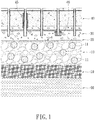
- a water permeable paving layer 40 is set on the drain layer 30.
- rainwater that drops to the ground surface can be allowed to permeate all the ground layers artificially set above to penetrate to an underground water stratum 60 under an underground soil stratum 50, whereby rainwater can be conducted to the underground water stratum 60 deeply under the earth to serve as supplemental underground resources and also, the gradation layers can be modified to serve as an ecological gradation layer 10, which when used in combination with the water permeable paving layer 40, provides versatile functions and also form an excellent survival environment for soil microorganisms and earth protozoa.
- the interfacing layer 20 and the drain layer 30 can be used individually or in combination.
- the water permeable paving layer 40 is directly set atop the ecological gradation layer 10, and the interfacing layer 20 and the drain layer 30 are selectively added according to actual water drainage of the construction site to realize similar effects of water draining and protection against global warming.
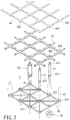
- the water permeable paving layer 40 (as shown in FIG 1 ) comprises a framework composed of a plurality of drainpipes 41 for draining water, an upper connection frame 42, a lower connection frame 43, a sealing lid moldboard 44, condensation pipes 45 having a function of air storage, and a water reservoir 46.
- the condensation pipe 45 provides a function of air storage and preservation, whereby in case of large area flooding, a survival space that provides air to underground microorganisms is kept.
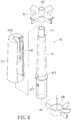
- Each of the drainpipes 41 has a top end portion forming a diameter-reduced section 411 and a bottom end portion forming a retention ring 412 and a retention wedge 413 (see FIG 4 ).
- the diameter-reduced section 411 on the top end of the drainpipe 41 can be directly fit into a barrel 421 formed on the upper connection frame 42, while the lower end of the drainpipe can be fit into a collar 431 formed on the lower connection frame 43 to allow the collar 431 received and retained between the retention ring 412 and retention wedge 413.
- the drainpipes 41 are hollow member.
- a plurality of sealing lids 441 is formed on the undersurface of the moldboard 44 so that during the pouring of cement mixture, the sealing lids 441 that are fit into top openings of the drainpipes 41 prevent the cement mixture from filling into and thus blocking the pipes (see FIG 3 ).
- the moldboard and the lids can then be removed after the pour cement mixture cures into solid to form a concrete-constructed water permeable paving layer.
- the condensation pipe 45 that has air storage function is constructed in such a way that, as shown in the embodiment illustrated in the drawings, an outer tube 414 is fit over and coupled to a drainpipe 41.
- the outer tube 414 has a top forming a hole 4141.
- the outer tube 414 forms a circumferential gap 4142 therein, so that the combination of a drainpipe 41 and an outer tube 414 forms a drainpipe structure that is capable of water draining, air ventilation, and water condensation and collection.
- the circumferential gap 4142 can be formed as being delimited by an inside surface of an outer tube and an outside surface of a drainpipe when the outer tube and the drainpipes are combined to each other.
- the water reservoir 46 is coupled to an end, particularly the bottom end, of a drainpipe 41.
- the water reservoir 46 comprises a top cover 461 and a base box 462.
- the top cover 461 has a top forming a hole 4611, and a rim 4612 is formed along a circumference of the top cover.
- the top cover 461 has an outside diameter greater than an outside diameter of the base box 462 and this helps preventing cement grout or slurry from getting into the base box during grouting or preventing sand of the drain layer from entering the base box.
- the base box 462 comprises a central tube 4621 and a circumferential gap 4622 around the central tube.
- the base box has a top forming spaced spot projections 4623.
- the central tube 4621 has an inside surface on which raised ribs 4624 are formed to help retaining the base box 462 when the base box is fit to the lower end of the drainpipe, so that the drainpipe 41 and the water reservoir 46 are combined together to form a structure of drainpipe that is capable of water draining, air ventilation, and water storage/preservation.
- the spot projections 4623 function to provide a gap for water inlet passage between the top cover 461 and the base box 462 when they are fit to each other.
- the central tube 4621 is formed so that a top end of the central tube is located higher than the top of the outer circumferential wall of the base box 462, so that when the top cover 461 and the base box 462 are fit to each other, a gap is formed to serve as water inlet passage.
- the ecological gradation layer 10 is generally formed of hollow bodies 11, in combination of on-site earth, including aggregates, soils, gravels, or a mixture of water permeable concrete, and additionally and selectively comprising other gradation materials that are of no harm to the environment, such as earthenware particles.
- the hollow bodies 11 that show unique functions are preferably in the form of sphere, for a spherical structure is more resistant to compression stress from any direction and provide voids for the gradation layer. However, other shapes that can be readily manufactured may also be adopted.
- the hollow body 11 is composed of two halves, each constituting a shell member 111.
- the hollow body is made of plastics, but they can be made of other traditionally used materials.
- the shell members of the hollow body are made of a wall of great thickness and each shell member 111 forms a plurality of through apertures 112.
- the hollow bodies 11 used in the present invention can be made as engineering hollow body for different uses, such as a disaster-prevention water-storage hollow body, or an earth improvement hollow body, or a microorganism-culture hollow body or a water-keeping hollow body, or any type of hollow body that meet the need for on-site use.
- the disaster-prevention water-storage hollow body as shown in the embodiment illustrated in the drawings, comprises two shell members 111, which are combined with each other to form a hollow body that carries through apertures 112 formed therein.
- the hollow bodies are mixed in the gradation layer, in case of extremely high precipitation, when the water permeable paving layer 40 needs to efficiently conduct away the rainwater, which leads to immediate saturation of water content in the gradation layer 10, water can be guided by the apertures 112 of the shells into the interior space of the hollow body, so that the chance for surface flooding in the related area can be prevented.
- penetration gradually conducts the water into the underground water stratum, and then the water received in the disaster-prevention water-storage hollow bodies is allowed to slowly release. This ensures an effect of efficient water drain for the ground surface.
- the earth-improvement hollow body is constructed with two shell members 111, which are combined with each other to form an interior space in which a carbon-contained substance 113, such as active carbon or binchotan, or an earth-improvement agent desired for improvement of local earth, is filled, whereby when the earth-improvement hollow bodies are mixed in the gradation layer, the carbon-contained substance 113 functions to absorb and activate acidifying substance or harmful substance entraining water that penetrates downward and passes through the earth-improvement hollow bodies or that contained in the surrounding soil, so as to realize improvement of earth quality.
- a carbon-contained substance 113 such as active carbon or binchotan, or an earth-improvement agent desired for improvement of local earth
- the microorganism-culture hollow body is composed of two shell members 111, which are combined to form an interior in which selected microbial strains 114 are deposited to serve as an excellent culture site for a large quantity of microorganisms.
- microorganisms With the microorganism-culture hollow bodies mixed in the gradation layer, microorganisms can be effectively cultured and an improved environment for propagation is provided.
- the microorganisms so cultured can help decomposing organic substance contained in the soil, prompting nitrification, performing de-nitrification, and improving ecological environment of earth.
- the water-keeping hollow body is composed of two shell members 111, which are combined to form an interior in which a water absorption substance 115 is filled, such as sponge or other water absorptive material that are not decomposable by microorganisms, so that when the water-keeping hollow bodies are mixed in the gradation layer, the water absorption substance 115 helps to absorb water when water flows through the hollow bodies so as to keep water from flowing away from the earth that ensures sufficient supply for survival and propagation of microorganisms and also improving water preservation and increasing water content in dry area.
- the high content of water in the earth allows water to be converted into vapor that is then released to the environment for heat exchange with the environment so that the heat island effect can be eliminated or alleviated.
- the water permeable paving layer 40 comprises, in structure thereof, a plurality of condensation pipes 45 having air storage function, and an upper connection frame 42 and a lower connection frame 43 respectively attached to top and bottom ends of the condensation pipes.
- Each condensation pipe 45 forms therein a circumferential gap 4142.
- vapor or humid from the underground drain layer 30 of which the soil has a temperature higher than the surrounding temperature above the ground surface may be converted into condensed water 4143 on the wall surfaces of the circumferential gap 4142, so that water can be extracted from the atmosphere to realize natural replenishment of soil water.
- the condensation pipe 45 having water storage function due to a closed top end of the circumferential gap 4142, forms an enclosed air storage, whereby an emergency shelter is provided for preservation and supply of air to microorganisms or earth protozoa, which, in a flooded area, can survive from drowning by taking the air preserved in the shelter
- the survival of microorganisms or protozoa can ensure quick recovery in a short period and also offer helps to organic substance contained in the soil.
- the water permeable paving layer 40 comprises, structurally, a plurality of water reservoirs 46 which function to store and accumulate water therein, and drainpipes 41 fixed between an upper connection frame 42 and a lower connection frame 43 for draining water. At least one or each of the drainpipes 41 has a bottom end to which each water reservoir 46 is attached (see FIG 3 ).
- the water reservoir 46 is composed of a top cover 461 and a base box 462.
- the base box has a central tube 4621 having a top end that is located higher position or spaced spot projections 4623 are provided (see FIGS. 5 and 9 ), so as to form a water inlet passage.
- the water permeable paving layer is constructed in such a way that after leveling of ground and setting of an ecological gradation layer 10, a paving layer 40a is formed on the ecological gradation layer 10.
- the paving layer 40a comprises reinforcement bars 402 and the reinforcement bars 402 are arranged in a tessellate form or added with other reinforcement materials. Cement grout is then poured over the reinforcement and a rigid concrete paving is formed after the grout cures.
- the paving layer 40a is not formed of concrete and reinforcement, and instead the paving layer is made of asphalt.
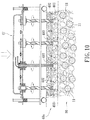
- Hole drilling tools 47 are then used to form a plurality of drain holes 403 in the rigid paving surface.
- Condensation pipes 45a capable of water draining and air storage (see FIG 11 ) or water storage pipes 46a capable of water draining and water storage (see FIG 14 ), which are made in the form of individual pipes, are used in combination or individually according to the environment of the construction site. At least one of these two pipes are selected and fit into the drain holes 403 that are formed in advance. In this way, an artificial paving that helps improving global warming is similarly realized.
- the condensation pipe 45a capable of water draining and air storage in the form of individual pipe shown in FIG 10 comprises, structurally, an inner tube 41a and an outer tube 414a.
- the inner tube 41a is a hollow tube having a top forming a diameter-expanded circumferential flange 415.
- the outer tube 414a has a top forming a hole 4141.
- the outer tube 414a has an inside wall forming a sloped inside surface 4144.
- the outer tube 414a has an outside wall forming raised structures 4145.
- the ecological gradation layer 10 When the paving layer 40a that allows for water permeation is flooded, the ecological gradation layer 10 is completely saturated with water and the excessive water is guided into the circumferential gap 4142 (see FIG 13 ). However, an amount of air is preserved in the top portion of the circumferential gap so that a space for breathing and survival is provided for microorganisms and protozoa inhabiting in the surrounding earth in case of flooding. Also, the wall surfaces of the circumferential gap between the outer tube 414a and the inner tube 41a may constitute a structure for water condensation.
- the water storage pipe 46a capable of water draining and water storage in the form of individual pipe shown in FIG 10 comprises, structurally, a water drain tube 41b to which a water reservoir 46 is attached.
- the water reservoir 46 is composed of a top cover 461 and a base box 462.
- the top cover 461 has a top forming a hole 4611, and a rim 4612 is formed along a circumference of the top cover.
- the top cover 461 has an outside diameter greater than an outside diameter of the base box 462.
- the base box 462 comprises a central tube 4621 and a circumferential gap 4622 around the central tube.
- the base box has a top forming spaced spot projections 4623.
- the central tube 4621 has an inside surface on which raised ribs 4624 are formed to help retaining the base box with interference fitting realized by the raised ribs 4624 when the base box 462 is fit to an end of water drain tube 41b, so that the water drain tube 41b and the water reservoir 46 can be combined together to form a water storage pipe 46a that is capable of both water draining and water storage.
- the top of the base box 462 is provided with the spot projections 4623 in order to form a water inlet passage.
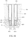
- the central tube 4621 is arranged to have a top A thereof located higher than a top B of an outer wall of the base box 462 (see FIG 16 ), so that a water inlet passage can be formed between the top cover 461 and the base box 462 when they are fit to each other.
- the paving layer 40a is constructed as a water permeable paving layer.
- Rainwater falling on the paving layer 40a that allows for water permeation is conducted to the underside ecological gradation layer 10, and once the underside ecological gradation layer 10 get saturated with water, excessive water is guided through the water inlet passage into the circumferential gap 4622 to be accumulated and stored therein.
- the water so stored can serve as a water supply for microorganisms and protozoa inhabiting in the surrounding earth in case of draught. This also effects regulation of the underground water temperature and humidity to maintain living of plants and also to prevent desertification.
- an interfacing layer or a drain layer, or both can be selectively added between the ecological gradation layer 10 and the water permeable paving layer 40a according to the local earth quality.
- FIG 17 an alternative form of water storage pipe according to the present invention is shown, which is made in the form of an individual water storage pipe 46b capable of water draining and water storage.
- the water storage pipe 46b comprises, structurally, a water drain tube 41c and a base box 462 attached thereto.
- the water drain tube 41c has a top having an outer circumference along which a rim 416 is formed in such a way that the rim 416 has an outside diameter greater than an outside diameter of the base box 462.
- the base box 462 comprises a central tube 4621 and a circumferential gap 4622.
- the base box has a top forming spaced spot projections 4623.
- the central tube 4621 has an inside surface on which raised ribs 4624 are formed to help retaining the base box with interference fitting realized by the raised ribs 4624 when the base box 462 is fit to an end of water drain tube 41c, so that a water storage pipe 46b that is capable of both water draining and water storage is provided.
- the top of the base box 462 is provided with the spot projections 4623 in order to form a water inlet passage.
- the central tube 4621 is arranged to have a top A thereof located higher than a top B of an outer wall of the base box 462, so that a water inlet passage can be formed between the top cover 461 and the base box 462 when they are fit to each other.
- the ecological gradation layer 10 can be formed of on-site earth or gradation material traditionally used for road construction, which may comprise aggregates, soils, gravels, and a mixture of concrete, and may additionally comprise other gradation materials that are of no harm to the environment.
- the gradation layer comprises hollow bodies 11, which unique functions.
- the hollow bodies 11 can be arranged in such a way that a plurality of hollow bodies are received and held in a net bag to form a bag-contained hollow body unit 12.
- the bag-contained hollow body units 12 can be directly laid as a gradation layer, or alternatively, the hollow body units 12 can be mixed with earth to form a gradation layer.
Landscapes
- Engineering & Computer Science (AREA)
- Architecture (AREA)
- Civil Engineering (AREA)
- Structural Engineering (AREA)
- Road Paving Structures (AREA)
- Sewage (AREA)
Description
- The present invention generally relates to a method for manufacturing artificial paving that help improving global warming, and more particularly to artificial paving that is constituted by an underground ecological gradation layer and an artificial water-permeable surface paving layer, which allows rainwater to be efficiently and effectively conducted into the underground gradation layer to effect storage of rainwater and reduction of surface flooding and also to form an excellent propagation environment in earth of the ecological gradation layer for microbial strains and earth protozoa for biological diversity, thereby helping maintaining soil wet and thus realizing regulation of temperature and humidity of the surrounding and improving quality of earth.
- Generally, conventional construction of concrete paving is done by pouring a sufficient amount of cement grout on the ground, leveling the cement grout, and then setting brick tiles thereon, to thereby form artificial concrete paving.
- The conventional paving according is made of concrete or a combination of concrete and bricks, and concrete is generally water impermeable. Even though the concrete is water permeable one, pores of the concrete are easily blocked. Further, the concrete may generate calcium oxide, which blocks the pores and cannot be removed and cleaned, so that water permeability may get much lower than the precipitation rate. When rainwater is accumulated on the ground, if it cannot be efficiently discharged into the underside soil, flood disasters may result easily due to accumulation of a large amount of precipitation.
- In the construction of regular roads or in the urban areas, paving for ground of construction site is often made integrally as a water impermeable surface paving layer. This prevents underside soil from contacting the atmosphere existing above the paving and replenishment of underground water with precipitation is blocked off. This causes damage to the environment. Apparently, such a concrete made paving structure that is water impermeable is not an ideal one. In cities, when it rains, the ground surface lacks of sufficient water permeation and thus most of the rainwater must be drained through unban sewage systems. Rainwater may finally be collected in underground main ducts of the sewage systems to be discharged to seas or oceans. This is just a water of the natural resources of rainwater. Further, the rainwater, once conducted to a low altitude area, may result in flooding disasters.
- As the soil has the function of absorbing water, and can vaporize humidity when contacting the atmosphere in a dry or hot environment to generate a heat exchange effect with the atmosphere, and may automatically regulate the humidity so as to avoid the occurrence of heat island effect.
- It is known that without efficient water permeability, rainwater drainage on ground surface will become poor. Thus, it is of importance to construct a gradation layer that is effective in maintaining water permeability and preservation of water. Further, to improve earth and ecological environment in earth, an environment that is beneficial to microorganisms and earth protozoa inhabiting in earth. The microorganisms inhabiting in earth generally include bacteria (eubacteria and archaea), fungi (filamentous fungi and yeasts), and algae. The earth protozoa include for example amoeba and ciliates. There are a huge number of ciliates existing in earth, and they make a great contribution for decomposition of organic substances. Insects, including ants, centipedes, aphids, and mites, help moving soils or digests residual body portions of organisms and thus providing organic substances. Earthworms may help formation of soil pellets, which are good for air ventilation and water draining. Nematodes help digesting organic matters or other small creatures. There are also vertebrates inhabiting in earth, such as mice, which dig and loosen soil, and provide excrements for fertilizing earth. They are also a member of an underground food chain.
- Earth microorganisms play an important role in keeping quality of earth. The existence of earth organisms is a vital factor for change and quality of earth environment.
- Studies show the importance of microorganisms to earth is as follows:
- (1) decomposition of organic substances and performance of mineralization by fully decomposing organic substances to nutrient elements;
- (2) fixation of nitrogen (N2) in atmosphere and conversion into NH3, serving as useful resources of nitrogen for organisms;
- (3) prompting nitrification, which converts NH4 + into nitrite nitrogen (NO2 -), and then nitrate nitrogen (NO3 -) for easy absorption by plants;
- (4) performing de-nitrification, which converts NO3 - into N2O and N2;
- (5) prompting dissolution of coupled or fixed chemical compounds of for example phosphorous, sulfur, iron, and manganese; and
- (6) interaction with other earth microorganisms, which play an important role of the survival of such other microorganisms in the environment.
- Thus, constructing a good environment for mass propagation of earth microorganisms is beneficial for improvement of earth. Further, formation of a water preservation gradation layer under an artificial paving layer allows for mutual contact with a top surface of the water permeable paving layer. Through mutual contact between soil and the atmosphere, heat exchange due to humidity and temperature is conducted just like respiration, helping realizing efficient water drainage and eliminating potential risk of surface accumulation of water, thus providing a practical effect.
- In view of the above discussed issue, the present invention aims to provide a method for manufacturing artificial paving that helps improving global warming and allows for construction of concrete paving that shows water permeability and environmental protection feature to allow underside gradation layers to become an ecological gradation layer to activate organic substances contained in soil and improve global warming problem.
- Prior art documents are known, such as
WO 2005/113900 A1 andWO 02/40784 A2 WO 2005/113900 A1 discloses an environmental water resource recycling system that comprises a plurality of drainpipe units buried in a concrete layer to allow rainwater to flow through the concrete layer so as to drain rainwater to a sand layer for recycling of the rainwater.WO 02/40784 A2 - Thus, an objective of the present invention is to provide a method for manufacturing artificial paving that helps improving global warming for quickly conducting rainwater falling on ground surface downward into the underground soil, wherein an artificial paving having high water permeability is formed to reduce potential risk of flooding on ground surface, accumulate and store water, and help recycling water resources of precipitation.
- Another objective of the present invention is to provide a method for manufacturing artificial paving that helps improving global warming, which converts an underground gradation layer into an ecological gradation layer, which ensure high water content so that when the outside temperature gets high, drainpipes of the artificial paving allow water contained underground to be converted into vapor to be released to the atmosphere in order to regulate surrounding temperature and humidity and thus eliminate or alleviate heat island effect.
- A further objective of the present invention is to provide a method for manufacturing artificial paving that helps improving global warming, which comprises an underground ecological gradation layer that uses a water permeable surface paving layer to enhance water absorption thereof and also provide drainpipes capable of water draining and water storage and drainpipes capable of water draining and water condensation under the ground so that through a huge number of drainpipes installed in this way to conduct surface rainwater into the underside gradation layers, allowing water to penetrate down into the underground water stratum, whereby the water permeable artificial paving layer enhances the formation of an excellent environment thereunder for microorganisms and earth protozoa inhabiting in the surrounding earth, and the gradation layer is formed as an ecological gradation layer, so that an effect of improving global warming is realized between earth and atmosphere on ground surface.
- To achieve the above objectives, the present invention provides a method having the features of
claim 1. The foregoing objectives and summary provide only a brief introduction to the present invention. To fully appreciate these and other objects of the present invention as well as the invention itself, all of which will become apparent to those skilled in the art, the following detailed description of the invention and the claims should be read in conjunction with the accompanying drawings. Throughout the specification and drawings identical reference numerals refer to identical or similar parts. - Many other advantages and features of the present invention will become manifest to those versed in the art upon making reference to the detailed description and the accompanying sheets of drawings in which a preferred structural embodiment incorporating the principles of the present invention is shown by way of illustrative example.
-
-
FIG 1 is a schematic view showing an artificial geological layer constructed in accordance with the present invention. -
FIG 2 is an exploded view of water draining structure of a water permeable paving according to the present invention. -
FIG 3 is a perspective view of the water draining structure of the water permeable paving according to the present invention in an assembled form. -
FIG 4 is an exploded view of a drainpipe capable of air storage according to the present invention. -
FIG 5 is an exploded view of a water reservoir according to the present invention. -
FIG 6 is a schematic view showing a gradation layer containing hollow bodies mixed therein according to the present invention. -
FIG 7 is an exploded view showing various structures of hollow bodies that provide different functions according to the present invention. -
FIG 8 is a cross-sectional view showing a draining and condensation pipe contained in water permeable paving according to the present invention. -
FIG 9 is a cross-sectional view showing a water draining and water storage pipe contained in water permeable paving according to the present invention. -
FIG 10 is a cross-sectional view showing another embodiment according to the present invention in which drain holes is drilled in concrete paving. -
FIG 11 is an exploded view of a condensation pipe capable of water draining and air storage according to another embodiment of the present invention. -
FIG 12 is perspective view of the pipeFIG 11 in an assembled form. -
FIG 13 is a cross-sectional view showing the pipe ofFIG 11 embedded in concrete paving according to the present invention. -
FIG 14 is an exploded view of a water storage pipe capable of water draining and water storage according to another embodiment of the present invention. -
FIG 15 is a perspective view of the pipe ofFIG 14 in an assemble form. -
FIG 16 is a cross-sectional view showing the pipe ofFIG 14 embedded in concrete paving according the present invention. -
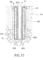
FIG 17 is a cross-sectional view showing an alternative form of the water storage pipe of the present invention shown inFIG 14 . -
FIG 18 is a cross-sectional view showing an ecological gradation layer not according to the present invention. - The following descriptions are exemplary embodiments only, and are not intended to limit the scope, applicability or configuration of the invention in any way. Rather, the following description provides a convenient illustration for implementing exemplary embodiments of the invention. Various changes to the described embodiments may be made in the function and arrangement of the elements described without departing from the scope of the invention as set forth in the appended claims.
- Referring to
FIG 1 , the present invention provides a method for manufacturing artificial paving that help improving global warming, which comprises, after leveling of ground surface, laying anecological gradation layer 10. Theecological gradation layer 10 may be on-site earth and/or gradation material commonly used for road construction, including aggregates, soils, gravels, a mixture of water-permeable concrete, and additionally and of importance, comprising uniquehollow bodies 11. All the constituent components are mixed and laid on the bottom, and then, after pressurization for ramming, aninterfacing layer 20 is selectively and additionally set thereon. Theinterfacing layer 20 may comprise a piece of non-woven fabric or a net, or a layer of sand. Atop theinterfacing layer 20, adrain layer 30 is set. The drain layer is composed of gravels (or crushed stones) or sand or a combination of both. Finally, a waterpermeable paving layer 40 is set on thedrain layer 30. With such an arrangement, rainwater that drops to the ground surface can be allowed to permeate all the ground layers artificially set above to penetrate to anunderground water stratum 60 under anunderground soil stratum 50, whereby rainwater can be conducted to theunderground water stratum 60 deeply under the earth to serve as supplemental underground resources and also, the gradation layers can be modified to serve as anecological gradation layer 10, which when used in combination with the waterpermeable paving layer 40, provides versatile functions and also form an excellent survival environment for soil microorganisms and earth protozoa. - The
interfacing layer 20 and thedrain layer 30 can be used individually or in combination. Alternatively, the waterpermeable paving layer 40 is directly set atop theecological gradation layer 10, and theinterfacing layer 20 and thedrain layer 30 are selectively added according to actual water drainage of the construction site to realize similar effects of water draining and protection against global warming. - Referring to
FIGS. 2 and3 , the water permeable paving layer 40 (as shown inFIG 1 ) comprises a framework composed of a plurality ofdrainpipes 41 for draining water, anupper connection frame 42, alower connection frame 43, a sealinglid moldboard 44,condensation pipes 45 having a function of air storage, and awater reservoir 46. Thecondensation pipe 45 provides a function of air storage and preservation, whereby in case of large area flooding, a survival space that provides air to underground microorganisms is kept. Each of thedrainpipes 41 has a top end portion forming a diameter-reducedsection 411 and a bottom end portion forming aretention ring 412 and a retention wedge 413 (seeFIG 4 ). The diameter-reducedsection 411 on the top end of thedrainpipe 41 can be directly fit into abarrel 421 formed on theupper connection frame 42, while the lower end of the drainpipe can be fit into acollar 431 formed on thelower connection frame 43 to allow thecollar 431 received and retained between theretention ring 412 andretention wedge 413. Thedrainpipes 41 are hollow member. During pouring of cement slurry or grout, to securely retain the sealinglid moldboard 44 in position and prevent cement mixture undesirably filling into and thus blocking the drainpipes, a plurality of sealinglids 441 is formed on the undersurface of themoldboard 44 so that during the pouring of cement mixture, the sealinglids 441 that are fit into top openings of thedrainpipes 41 prevent the cement mixture from filling into and thus blocking the pipes (seeFIG 3 ). The moldboard and the lids can then be removed after the pour cement mixture cures into solid to form a concrete-constructed water permeable paving layer. - Referring to
FIG 4 , thecondensation pipe 45 that has air storage function is constructed in such a way that, as shown in the embodiment illustrated in the drawings, anouter tube 414 is fit over and coupled to adrainpipe 41. Theouter tube 414 has a top forming ahole 4141. Theouter tube 414 forms acircumferential gap 4142 therein, so that the combination of adrainpipe 41 and anouter tube 414 forms a drainpipe structure that is capable of water draining, air ventilation, and water condensation and collection. In an alternative embodiment, thecircumferential gap 4142 can be formed as being delimited by an inside surface of an outer tube and an outside surface of a drainpipe when the outer tube and the drainpipes are combined to each other. - Referring to
FIG 5 , thewater reservoir 46 is coupled to an end, particularly the bottom end, of adrainpipe 41. Structurally, thewater reservoir 46 comprises atop cover 461 and abase box 462. Thetop cover 461 has a top forming ahole 4611, and arim 4612 is formed along a circumference of the top cover. Thetop cover 461 has an outside diameter greater than an outside diameter of thebase box 462 and this helps preventing cement grout or slurry from getting into the base box during grouting or preventing sand of the drain layer from entering the base box. Thebase box 462 comprises acentral tube 4621 and acircumferential gap 4622 around the central tube. The base box has a top forming spacedspot projections 4623. Thecentral tube 4621 has an inside surface on which raisedribs 4624 are formed to help retaining thebase box 462 when the base box is fit to the lower end of the drainpipe, so that thedrainpipe 41 and thewater reservoir 46 are combined together to form a structure of drainpipe that is capable of water draining, air ventilation, and water storage/preservation. Thespot projections 4623 function to provide a gap for water inlet passage between thetop cover 461 and thebase box 462 when they are fit to each other. In an alternative embodiment, thecentral tube 4621 is formed so that a top end of the central tube is located higher than the top of the outer circumferential wall of thebase box 462, so that when thetop cover 461 and thebase box 462 are fit to each other, a gap is formed to serve as water inlet passage. - Referring to
FIGS. 6 and7 , theecological gradation layer 10 is generally formed ofhollow bodies 11, in combination of on-site earth, including aggregates, soils, gravels, or a mixture of water permeable concrete, and additionally and selectively comprising other gradation materials that are of no harm to the environment, such as earthenware particles. Thehollow bodies 11 that show unique functions are preferably in the form of sphere, for a spherical structure is more resistant to compression stress from any direction and provide voids for the gradation layer. However, other shapes that can be readily manufactured may also be adopted. Thehollow body 11 is composed of two halves, each constituting ashell member 111. Preferably, the hollow body is made of plastics, but they can be made of other traditionally used materials. The shell members of the hollow body are made of a wall of great thickness and eachshell member 111 forms a plurality of throughapertures 112. Thehollow bodies 11 used in the present invention can be made as engineering hollow body for different uses, such as a disaster-prevention water-storage hollow body, or an earth improvement hollow body, or a microorganism-culture hollow body or a water-keeping hollow body, or any type of hollow body that meet the need for on-site use. - The disaster-prevention water-storage hollow body, as shown in the embodiment illustrated in the drawings, comprises two
shell members 111, which are combined with each other to form a hollow body that carries throughapertures 112 formed therein. Thus, when the hollow bodies are mixed in the gradation layer, in case of extremely high precipitation, when the waterpermeable paving layer 40 needs to efficiently conduct away the rainwater, which leads to immediate saturation of water content in thegradation layer 10, water can be guided by theapertures 112 of the shells into the interior space of the hollow body, so that the chance for surface flooding in the related area can be prevented. With sufficient time lapse, penetration gradually conducts the water into the underground water stratum, and then the water received in the disaster-prevention water-storage hollow bodies is allowed to slowly release. This ensures an effect of efficient water drain for the ground surface. - The earth-improvement hollow body is constructed with two
shell members 111, which are combined with each other to form an interior space in which a carbon-containedsubstance 113, such as active carbon or binchotan, or an earth-improvement agent desired for improvement of local earth, is filled, whereby when the earth-improvement hollow bodies are mixed in the gradation layer, the carbon-containedsubstance 113 functions to absorb and activate acidifying substance or harmful substance entraining water that penetrates downward and passes through the earth-improvement hollow bodies or that contained in the surrounding soil, so as to realize improvement of earth quality. - The microorganism-culture hollow body is composed of two
shell members 111, which are combined to form an interior in which selectedmicrobial strains 114 are deposited to serve as an excellent culture site for a large quantity of microorganisms. With the microorganism-culture hollow bodies mixed in the gradation layer, microorganisms can be effectively cultured and an improved environment for propagation is provided. The microorganisms so cultured can help decomposing organic substance contained in the soil, prompting nitrification, performing de-nitrification, and improving ecological environment of earth. - The water-keeping hollow body is composed of two
shell members 111, which are combined to form an interior in which awater absorption substance 115 is filled, such as sponge or other water absorptive material that are not decomposable by microorganisms, so that when the water-keeping hollow bodies are mixed in the gradation layer, thewater absorption substance 115 helps to absorb water when water flows through the hollow bodies so as to keep water from flowing away from the earth that ensures sufficient supply for survival and propagation of microorganisms and also improving water preservation and increasing water content in dry area. In case of high temperature on the ground surface, the high content of water in the earth allows water to be converted into vapor that is then released to the environment for heat exchange with the environment so that the heat island effect can be eliminated or alleviated. - Referring to
FIG 8 , the waterpermeable paving layer 40 comprises, in structure thereof, a plurality ofcondensation pipes 45 having air storage function, and anupper connection frame 42 and alower connection frame 43 respectively attached to top and bottom ends of the condensation pipes. Eachcondensation pipe 45 forms therein acircumferential gap 4142. In a cold zone, when the surrounding temperature is low, vapor or humid from theunderground drain layer 30 of which the soil has a temperature higher than the surrounding temperature above the ground surface may be converted into condensedwater 4143 on the wall surfaces of thecircumferential gap 4142, so that water can be extracted from the atmosphere to realize natural replenishment of soil water. In case of precipitation, rainwater that falls on the surface paving layer is guided bywater conduction grooves 401 into thebarrel 421, flowing downward into thedrainpipe 41, and entering thedrain layer 30, so that water can be effectively collected, avoiding the water directly flowing along sewage system to the oceans, which represents a waste of water resources. Further, in case of extremely heavy precipitation that leads to flooding, thecondensation pipe 45 having water storage function, due to a closed top end of thecircumferential gap 4142, forms an enclosed air storage, whereby an emergency shelter is provided for preservation and supply of air to microorganisms or earth protozoa, which, in a flooded area, can survive from drowning by taking the air preserved in the shelter The survival of microorganisms or protozoa can ensure quick recovery in a short period and also offer helps to organic substance contained in the soil. - Referring to
FIGS. 3 ,5 , and9 , the waterpermeable paving layer 40 comprises, structurally, a plurality ofwater reservoirs 46 which function to store and accumulate water therein, anddrainpipes 41 fixed between anupper connection frame 42 and alower connection frame 43 for draining water. At least one or each of thedrainpipes 41 has a bottom end to which eachwater reservoir 46 is attached (seeFIG 3 ). Thewater reservoir 46 is composed of atop cover 461 and abase box 462. The base box has acentral tube 4621 having a top end that is located higher position or spacedspot projections 4623 are provided (seeFIGS. 5 and9 ), so as to form a water inlet passage. When thedrain layer 30 get saturated with water, water that penetrates downward is guided through the air inlet passage into acircumferential gap 4622 formed in the water reservoir to be accumulated and stored therein. Such stored water ensures water supply for microorganisms or protozoa inhabiting in the surrounding earth in case of draught for the survival of these microorganisms and protozoa. This also effects regulation of the underground water temperature and humidity to maintain living of plants and also to prevent desertification. - Referring to
FIGS. 10 ,11 , and14 , another embodiment of the present invention is illustrated, wherein the water permeable paving layer is constructed in such a way that after leveling of ground and setting of anecological gradation layer 10, apaving layer 40a is formed on theecological gradation layer 10. Preferably, thepaving layer 40a comprises reinforcement bars 402 and the reinforcement bars 402 are arranged in a tessellate form or added with other reinforcement materials. Cement grout is then poured over the reinforcement and a rigid concrete paving is formed after the grout cures. Alternatively, thepaving layer 40a is not formed of concrete and reinforcement, and instead the paving layer is made of asphalt.Hole drilling tools 47 are then used to form a plurality of drain holes 403 in the rigid paving surface.Condensation pipes 45a capable of water draining and air storage (seeFIG 11 ) orwater storage pipes 46a capable of water draining and water storage (seeFIG 14 ), which are made in the form of individual pipes, are used in combination or individually according to the environment of the construction site. At least one of these two pipes are selected and fit into the drain holes 403 that are formed in advance. In this way, an artificial paving that helps improving global warming is similarly realized. - Referring to
FIGS. 11, 12 , and13 , thecondensation pipe 45a capable of water draining and air storage in the form of individual pipe shown inFIG 10 comprises, structurally, aninner tube 41a and anouter tube 414a. Theinner tube 41a is a hollow tube having a top forming a diameter-expandedcircumferential flange 415. Theouter tube 414a has a top forming ahole 4141. Theouter tube 414a has an inside wall forming a sloped insidesurface 4144. Theouter tube 414a has an outside wall forming raisedstructures 4145. With thecondensation pipes 45a properly fit into the drain holes 403 formed in thepaving layer 40a (as shown inFIG 13 ), thepaving layer 40a forms a water permeable paving layer. When thepaving layer 40a that allows for water permeation is flooded, theecological gradation layer 10 is completely saturated with water and the excessive water is guided into the circumferential gap 4142 (seeFIG 13 ). However, an amount of air is preserved in the top portion of the circumferential gap so that a space for breathing and survival is provided for microorganisms and protozoa inhabiting in the surrounding earth in case of flooding. Also, the wall surfaces of the circumferential gap between theouter tube 414a and theinner tube 41a may constitute a structure for water condensation. - Referring to
FIGS. 14, 15 , and16 , thewater storage pipe 46a capable of water draining and water storage in the form of individual pipe shown inFIG 10 comprises, structurally, awater drain tube 41b to which awater reservoir 46 is attached. Thewater reservoir 46 is composed of atop cover 461 and abase box 462. Thetop cover 461 has a top forming ahole 4611, and arim 4612 is formed along a circumference of the top cover. Thetop cover 461 has an outside diameter greater than an outside diameter of thebase box 462. Thebase box 462 comprises acentral tube 4621 and acircumferential gap 4622 around the central tube. Preferably, the base box has a top forming spacedspot projections 4623. Thecentral tube 4621 has an inside surface on which raisedribs 4624 are formed to help retaining the base box with interference fitting realized by the raisedribs 4624 when thebase box 462 is fit to an end ofwater drain tube 41b, so that thewater drain tube 41b and thewater reservoir 46 can be combined together to form awater storage pipe 46a that is capable of both water draining and water storage. In the embodiment illustrated, the top of thebase box 462 is provided with thespot projections 4623 in order to form a water inlet passage. In an alternative embodiment, thecentral tube 4621 is arranged to have a top A thereof located higher than a top B of an outer wall of the base box 462 (seeFIG 16 ), so that a water inlet passage can be formed between thetop cover 461 and thebase box 462 when they are fit to each other. - As illustrated in the embodiment of
FIG 16 , when thewater storage pipe 46a is fit in adrain hole 403 that is previously formed in thepaving layer 40a (seeFIG 16 ), thepaving layer 40a is constructed as a water permeable paving layer. Rainwater falling on thepaving layer 40a that allows for water permeation is conducted to the undersideecological gradation layer 10, and once the undersideecological gradation layer 10 get saturated with water, excessive water is guided through the water inlet passage into thecircumferential gap 4622 to be accumulated and stored therein. The water so stored can serve as a water supply for microorganisms and protozoa inhabiting in the surrounding earth in case of draught. This also effects regulation of the underground water temperature and humidity to maintain living of plants and also to prevent desertification. - If desired, an interfacing layer or a drain layer, or both, can be selectively added between the
ecological gradation layer 10 and the waterpermeable paving layer 40a according to the local earth quality. - Referring to
FIG 17 , an alternative form of water storage pipe according to the present invention is shown, which is made in the form of an individualwater storage pipe 46b capable of water draining and water storage. Thewater storage pipe 46b comprises, structurally, awater drain tube 41c and abase box 462 attached thereto. Thewater drain tube 41c has a top having an outer circumference along which arim 416 is formed in such a way that therim 416 has an outside diameter greater than an outside diameter of thebase box 462. Thebase box 462 comprises acentral tube 4621 and acircumferential gap 4622. Preferably, the base box has a top forming spacedspot projections 4623. Thecentral tube 4621 has an inside surface on which raisedribs 4624 are formed to help retaining the base box with interference fitting realized by the raisedribs 4624 when thebase box 462 is fit to an end ofwater drain tube 41c, so that awater storage pipe 46b that is capable of both water draining and water storage is provided. - In the embodiment illustrated, the top of the
base box 462 is provided with thespot projections 4623 in order to form a water inlet passage. In an alternative embodiment, thecentral tube 4621 is arranged to have a top A thereof located higher than a top B of an outer wall of thebase box 462, so that a water inlet passage can be formed between thetop cover 461 and thebase box 462 when they are fit to each other. - Referring to
FIG 18 , in the embodiment illustrated and not falling under the scope of the claims, theecological gradation layer 10 can be formed of on-site earth or gradation material traditionally used for road construction, which may comprise aggregates, soils, gravels, and a mixture of concrete, and may additionally comprise other gradation materials that are of no harm to the environment. The gradation layer compriseshollow bodies 11, which unique functions. Thehollow bodies 11 can be arranged in such a way that a plurality of hollow bodies are received and held in a net bag to form a bag-containedhollow body unit 12. The bag-containedhollow body units 12 can be directly laid as a gradation layer, or alternatively, thehollow body units 12 can be mixed with earth to form a gradation layer. These also provide the same effects as discussed above. - It will be understood that each of the elements described above, or two or more together may also find a useful application in other types of methods differing from the type described above.
- While certain novel features of this invention have been shown and described and are pointed out in the annexed claim, it is not intended to be limited to the details above, since it will be understood that various omissions, modifications, substitutions and changes in the forms and details of the device illustrated and in its operation can be made by those skilled in the art without departing in any way from the scope of the present invention as defined by the claims.
Claims (13)
- A method for manufacturing artificial paving that helps improving global warming, mainly constituted by an ecological gradation layer (10) and a water permeable paving layer (40), wherein:after ground levelling, the ecological gradation layer (10) is laid first; andthe water permeable paving layer (40) is set on the ecological gradation layer (10);characterized in that the ecological gradation layer (10) is formed of gradation materials for road construction or on-site earth and hollow bodies (11) being mixed with the gradation materials or the on-site earth, each of the hollow bodies (11) comprising a shell composed of two halved shell members (111) jointed to each other to form an interior space, the hollow bodies (11) forming through apertures (112) communicating with the interior space, the hollow bodies (11) and the gradation materials or the on-site earth being laid and then subjected to pressurization for ramming;whereby rainwater falling on ground is allowed to effectively permeate the water permeable paving layer (40) and the ecological gradation layer (10) to reach an underground water stratum (60) that is located under an underground soil stratum (50), so that rainwater is conducted to deep location of ground to supplement the underground water stratum (60), and the ecological gradation layer (10) provides an excellent survival environment for microorganisms and protozoa inhabiting in earth.
- The method according to claim 1, wherein an interfacing layer (20) is additionally set above the ecological gradation layer (10) and below the water permeable paving layer (40).
- The method according to claim 1, wherein a drain layer (30) is additionally set above the ecological gradation layer (10) and below the water permeable paving layer (40).
- The method according to claim 2, wherein a drain layer (30) is set above the interfacing layer (20).
- The method according to claim 1, wherein the hollow bodies (11) are constructed as disaster-prevention water-storage hollow bodies (11).
- The method according to claim 1, wherein the hollow bodies (11) are constructed as earth-improvement hollow bodies (11), having their hollow interior spaces filled with a carbon-contained substance (113) or an earth-improvement agent.
- The method according to claim 1, wherein the hollow bodies (11) are constructed as microorganism-culture hollow bodies (11), having their hollow interior spaces set with microbial strains (114)
- The method according to claim 1, wherein the hollow bodies (11) are constructed as water-keeping hollow bodies (11), having their hollow interior spaces filled with a water absorption substance (115), including sponge or a water absorptive material that is not decomposable by microorganisms.
- The method according to claim 1, wherein each of the hollow bodies (11) is composed of two halved shell members (111) that mate each other.
- The method according to claim 2, wherein the interfacing layer (20) comprises a piece of non-woven fabric or a net, or a layer of sand.
- The method according to claim 3 or claim 4, wherein the drain layer (30) is composed of gravels, or sand, or a combination of both, or a sand-based gradation material.
- The method according to claim 1, wherein the water permeable paving layer (40) comprises a plurality of drainpipes (41), an upper connection frame (42), a lower connection frame (43), and condensation pipes (45) having a function of air storage, each of the condensation pipe (45) comprising an outer tube (414) mounted to the drainpipe (41), the outer tube (414) having a top forming a hole (4141), the outer tube (414) forming a circumferential gap (4142) therein, so that a combination of the drainpipe (41) and the outer tube (414) forms a drainpipe structure that is capable of water draining and collection of condensed water.
- The method according to claim 1, wherein the water permeable paving layer (40) comprises a plurality of drainpipes (41), an upper connection frame (42), a lower connection frame (43), and water reservoirs (46), each of the water reservoir (46) being attached to an end of one drainpipe (41), each of the water reservoirs (46) comprising a top cover (461) and a base box (462), the top cover (461) having a top forming a hole (4611), the top cover (461) having an outer circumference along which a rim (4612) is formed, the top cover (461) having an outside diameter greater than an outside diameter of the base box (462), the base box (462) comprising a central tube (4621) and a circumferential gap (4622), the central tube (4621) having a top located at a high position, the base box (462) having a top forming spaced spot projections (4623), which form a water inlet passage when the top cover (461) and the base box (462) are fit to each other, the central tube (4621) having an inside surface forming raised ribs (4624), whereby the drainpipe (41) and the water reservoir (46) are combined together to form a drainpipe structure capable of water draining and water storage.
Priority Applications (5)
| Application Number | Priority Date | Filing Date | Title |
|---|---|---|---|
| SM20180225T SMT201800225T1 (en) | 2010-10-19 | 2011-09-08 | Manufacturing process for artificial pavement for countering global warming |
| HRP20180701TT HRP20180701T1 (en) | 2010-10-19 | 2011-09-08 | PROCEDURE FOR MANUFACTURING AN ARTIFICIAL PATIENT AGAINST GLOBAL WARMING |
| PL11833694T PL2631364T3 (en) | 2010-10-19 | 2011-09-08 | Manufacturing process for artificial pavement for countering global warming |
| SI201131473T SI2631364T1 (en) | 2010-10-19 | 2011-09-08 | A process for producing artificial pressure to combat global warming |
| RS20180528A RS57173B1 (en) | 2010-10-19 | 2011-09-08 | Manufacturing process for artificial pavement for countering global warming |
Applications Claiming Priority (2)
| Application Number | Priority Date | Filing Date | Title |
|---|---|---|---|
| CN201010526375.3A CN102454143B (en) | 2010-10-19 | 2010-10-19 | Improving the manufacturing method of artificial paving for global warming |
| PCT/CN2011/001524 WO2012051788A1 (en) | 2010-10-19 | 2011-09-08 | Manufacturing process for artificial pavement for countering global warming |
Publications (3)
| Publication Number | Publication Date |
|---|---|
| EP2631364A1 EP2631364A1 (en) | 2013-08-28 |
| EP2631364A4 EP2631364A4 (en) | 2015-12-23 |
| EP2631364B1 true EP2631364B1 (en) | 2018-02-07 |
Family
ID=45974635
Family Applications (1)
| Application Number | Title | Priority Date | Filing Date |
|---|---|---|---|
| EP11833694.0A Active EP2631364B1 (en) | 2010-10-19 | 2011-09-08 | Manufacturing process for artificial pavement for countering global warming |
Country Status (17)
| Country | Link |
|---|---|
| EP (1) | EP2631364B1 (en) |
| KR (1) | KR101533897B1 (en) |
| CN (1) | CN102454143B (en) |
| CY (1) | CY1120198T1 (en) |
| DK (1) | DK2631364T3 (en) |
| ES (1) | ES2668209T3 (en) |
| HR (1) | HRP20180701T1 (en) |
| HU (1) | HUE037229T2 (en) |
| LT (1) | LT2631364T (en) |
| NO (1) | NO2631364T3 (en) |
| PL (1) | PL2631364T3 (en) |
| PT (1) | PT2631364T (en) |
| RS (1) | RS57173B1 (en) |
| RU (1) | RU2535566C1 (en) |
| SI (1) | SI2631364T1 (en) |
| SM (1) | SMT201800225T1 (en) |
| WO (1) | WO2012051788A1 (en) |
Cited By (1)
| Publication number | Priority date | Publication date | Assignee | Title |
|---|---|---|---|---|
| DE102022120632A1 (en) | 2022-08-16 | 2024-02-22 | Lutz Weiler | Road or sidewalk surface and process for its production |
Families Citing this family (26)
| Publication number | Priority date | Publication date | Assignee | Title |
|---|---|---|---|---|
| US20140170363A1 (en) | 2012-12-19 | 2014-06-19 | Intecrete, Llc | Layered architectural pervious concrete |
| CN105275076A (en) * | 2014-06-28 | 2016-01-27 | 冷庆林 | Road surface paving method |
| CN104532712B (en) * | 2014-12-25 | 2016-08-17 | 中交第二公路勘察设计研究院有限公司 | A kind of method for designing preventing and treating highway soft rock engineering sedimentation and deformation disease and structure |
| CN104612020A (en) * | 2015-01-19 | 2015-05-13 | 薛志东 | Structure of water-permeable pavement |
| CN104594154A (en) * | 2015-01-19 | 2015-05-06 | 薛志东 | Permeable support for pavement structure |
| CN104652214A (en) * | 2015-01-19 | 2015-05-27 | 薛志东 | Paving method of water-permeable pavement |
| CN104594155A (en) * | 2015-01-19 | 2015-05-06 | 薛志东 | Permeable pavement laying method |
| CN104846712B (en) * | 2015-03-12 | 2017-02-01 | 周太泽 | Hard Pavement Construction Method of Natural Groundwater Recharge |
| CN105133718B (en) * | 2015-09-22 | 2017-03-08 | 赵玉清 | It is applied to the water guiding system in sponge urban ecology ground system and construction method |
| CN105484122A (en) * | 2015-12-18 | 2016-04-13 | 路金铭 | Ecological permeable pavement and construction method thereof |
| CN105735088A (en) * | 2016-03-04 | 2016-07-06 | 浙江德安科技股份有限公司 | Pavement brick and pavement |
| CN106917340B (en) * | 2017-03-17 | 2019-04-26 | 张启志 | A kind of urban water control and dustproof sponge type road construction method |
| DE102017113307A1 (en) * | 2017-06-16 | 2018-12-20 | Intergreen Ag | Sports field superstructure and sports field |
| CN107386047B (en) * | 2017-08-10 | 2020-05-08 | 温州市环美建筑工程有限公司 | A kind of permeable brick pavement structure and construction method thereof |
| CN107881876A (en) * | 2017-11-27 | 2018-04-06 | 梅州九方生态建设有限公司 | A kind of permeable ecological pavement that draws water |
| CN108301280B (en) * | 2017-12-28 | 2020-06-16 | 北京建筑大学 | Permeable pavement structure |
| CN110894701A (en) * | 2018-09-13 | 2020-03-20 | 花基益 | Method and device for moisturizing, water permeability and adjusting microclimate |
| CN110863402A (en) * | 2019-04-25 | 2020-03-06 | 辛振科 | Water seepage device and method |
| CN110146434B (en) * | 2019-06-14 | 2024-03-26 | 广东工业大学 | An urban outdoor greenway cold plate testing device |
| CN110284391B (en) * | 2019-07-16 | 2020-12-08 | 中国港湾工程有限责任公司 | Airport asphalt pavement repairing method |
| CN111188239A (en) * | 2020-01-14 | 2020-05-22 | 蒋俊连 | Water storage and temperature adjustment floor tile for sponge city |
| CN111576132A (en) * | 2020-05-21 | 2020-08-25 | 中建水务环保有限公司 | Permeable block pavement permeable function repairing technology |
| CN112663425A (en) * | 2020-12-17 | 2021-04-16 | 江阴市晨辉市政建设工程有限责任公司 | Pavement structure capable of permeating water, storing water and draining water |
| CN112942010B (en) * | 2021-03-17 | 2024-03-19 | 重庆能源职业学院 | Energy-saving epoxy terrace structure |
| CN115992544A (en) * | 2021-10-20 | 2023-04-21 | 陈瑞文 | Photoelectric permeable pavement underground water storage automatic system |
| CN116716767B (en) * | 2023-06-06 | 2023-12-15 | 中国科学院西北生态环境资源研究院 | Integrated structure for repairing diseases of transition section of soil-frozen road bridge for many years |
Family Cites Families (19)
| Publication number | Priority date | Publication date | Assignee | Title |
|---|---|---|---|---|
| US692463A (en) * | 1901-06-28 | 1902-02-04 | Charles B Livingston | Door-latch. |
| US4411555A (en) * | 1979-07-17 | 1983-10-25 | Minvielle Monique L | Draining, irrigating and dispersing mass |
| EP0388496A1 (en) * | 1989-03-23 | 1990-09-26 | Rita Reuss | Process for producing humus |
| SU1663080A1 (en) * | 1989-06-20 | 1991-07-15 | Государственный всесоюзный дорожный научно-исследовательский институт | Method for erecting subgrade |
| KR19980027663A (en) * | 1996-10-17 | 1998-07-15 | 황익현 | Drainage concrete paving method |
| US6102613A (en) * | 1997-02-12 | 2000-08-15 | Medico, Jr.; John J. | Environmental porous paving material and pavement construction, environmental porous pavement mixing machine for mixing environmental porous pavement and methods for manufacturing porous material and constructions |
| US5906454A (en) * | 1997-02-12 | 1999-05-25 | Medico, Jr.; John J. | Environmental porous overlayer and process of making the same |
| CN1271042A (en) * | 1999-04-19 | 2000-10-25 | 张仲新 | Multi-purpose sports ground with artificial turf |
| TW465612U (en) * | 1999-06-11 | 2001-11-21 | Ruei-Wen Chen | Structure of water guiding pipe for environmental permeable concrete pavement |
| RU15735U1 (en) * | 2000-05-29 | 2000-11-10 | Щетков Виталий Анатольевич | CAPILLAR-BREAKING MEMBRANE OF ROAD CLOTHES |
| CA2326272A1 (en) * | 2000-11-17 | 2002-05-17 | Hun S. Kim | Sub-base drainage device |
| KR20010067731A (en) * | 2001-03-14 | 2001-07-13 | 최선용 | Elastic and Permeable concrete pavement structure to storing basic water |
| US6585449B2 (en) * | 2001-10-12 | 2003-07-01 | Jui-Wen Chen | Environment protecting gutter duct structure for a concrete roadway |
| US6962463B2 (en) * | 2003-09-02 | 2005-11-08 | Jui Wen Chen | Construction of environmental and water-permeable paving |
| JP2005264590A (en) * | 2004-03-19 | 2005-09-29 | Toa Doro Kogyo Co Ltd | Pavement structure and method for forming pavement structure |
| WO2005113900A1 (en) * | 2004-04-21 | 2005-12-01 | Jui Wen Chen | Method for installing water resource recycling system |
| RU2283910C2 (en) * | 2004-08-20 | 2006-09-20 | Елена Сергеевна Пшеничникова | Heat-insulation layer of road structure |
| KR100589057B1 (en) * | 2005-11-03 | 2006-06-12 | (주)네츄럴로드 | Permeable Asphalt Concrete with Flame Retardant Fiber and Its Manufacturing Method |
| US7351004B2 (en) * | 2006-07-19 | 2008-04-01 | Shaw & Sons, Inc. | Aquifer replenishment system |
-
2010
- 2010-10-19 CN CN201010526375.3A patent/CN102454143B/en active Active
-
2011
- 2011-09-08 ES ES11833694.0T patent/ES2668209T3/en active Active
- 2011-09-08 RS RS20180528A patent/RS57173B1/en unknown
- 2011-09-08 PT PT118336940T patent/PT2631364T/en unknown
- 2011-09-08 WO PCT/CN2011/001524 patent/WO2012051788A1/en not_active Ceased
- 2011-09-08 SM SM20180225T patent/SMT201800225T1/en unknown
- 2011-09-08 NO NO11833694A patent/NO2631364T3/no unknown
- 2011-09-08 KR KR1020137012556A patent/KR101533897B1/en not_active Expired - Fee Related
- 2011-09-08 DK DK11833694.0T patent/DK2631364T3/en active
- 2011-09-08 EP EP11833694.0A patent/EP2631364B1/en active Active
- 2011-09-08 HR HRP20180701TT patent/HRP20180701T1/en unknown
- 2011-09-08 SI SI201131473T patent/SI2631364T1/en unknown
- 2011-09-08 PL PL11833694T patent/PL2631364T3/en unknown
- 2011-09-08 RU RU2013121145/03A patent/RU2535566C1/en active
- 2011-09-08 HU HUE11833694A patent/HUE037229T2/en unknown
- 2011-09-08 LT LTEP11833694.0T patent/LT2631364T/en unknown
-
2018
- 2018-05-07 CY CY20181100477T patent/CY1120198T1/en unknown
Non-Patent Citations (1)
| Title |
|---|
| None * |
Cited By (1)
| Publication number | Priority date | Publication date | Assignee | Title |
|---|---|---|---|---|
| DE102022120632A1 (en) | 2022-08-16 | 2024-02-22 | Lutz Weiler | Road or sidewalk surface and process for its production |
Also Published As
| Publication number | Publication date |
|---|---|
| SI2631364T1 (en) | 2018-06-29 |
| NO2631364T3 (en) | 2018-07-07 |
| HRP20180701T1 (en) | 2018-06-01 |
| CY1120198T1 (en) | 2018-12-12 |
| PL2631364T3 (en) | 2018-07-31 |
| RS57173B1 (en) | 2018-07-31 |
| CN102454143A (en) | 2012-05-16 |
| KR101533897B1 (en) | 2015-07-06 |
| CN102454143B (en) | 2015-02-04 |
| WO2012051788A1 (en) | 2012-04-26 |
| DK2631364T3 (en) | 2018-05-07 |
| SMT201800225T1 (en) | 2018-07-17 |
| ES2668209T3 (en) | 2018-05-17 |
| EP2631364A4 (en) | 2015-12-23 |
| EP2631364A1 (en) | 2013-08-28 |
| PT2631364T (en) | 2018-05-15 |
| LT2631364T (en) | 2018-07-25 |
| HUE037229T2 (en) | 2018-08-28 |
| RU2013121145A (en) | 2014-11-27 |
| KR20130079594A (en) | 2013-07-10 |
| RU2535566C1 (en) | 2014-12-20 |
Similar Documents
| Publication | Publication Date | Title |
|---|---|---|
| US8267618B2 (en) | Method for manufacturing artificial paving that help improving global warming | |
| DK2631364T3 (en) | Method of producing artificial coating to combat global warming | |
| EP2631362A1 (en) | Method for manufacturing geological base course with disaster-preventive and ecological base course | |
| CA2751372C (en) | Method for manufacturing geological gradation featuring disaster prevention and ecologic function | |
| US8876432B2 (en) | Method for manufacturing geological gradation featuring disaster prevention and ecologic function | |
| ES2767374T3 (en) | Method for cooling a sports field | |
| EP3347523A1 (en) | Tree frame and grate system and method to improve growth of vegetation in an urban environment | |
| CN207062672U (en) | A kind of permeable pavement structure | |
| CN107143021A (en) | a bioretention pond | |
| CN207793792U (en) | A kind of road surface permeable pavement structure | |
| CN207130558U (en) | A kind of roadbed filling structure | |
| CN100417767C (en) | Water-permeable and environmentally friendly floor tiles for outdoor use | |
| CN116145697B (en) | A combined ecological slope protection system for self-adsorption of pollutants and its application | |
| CN107178021B (en) | A kind of sponge urban ecology square rainwater utilization structure enhancing water storage | |
| JPH10168985A (en) | Structure for promoting infiltration of surface water | |
| TWI840184B (en) | Permeable grass-covered underground water storage structure | |
| JP3042432U (en) | Rainwater play garden block | |
| CN121295574A (en) | A roadbed structure, road, and construction method for frozen soil highways |
Legal Events
| Date | Code | Title | Description |
|---|---|---|---|
| PUAI | Public reference made under article 153(3) epc to a published international application that has entered the european phase |
Free format text: ORIGINAL CODE: 0009012 |
|
| 17P | Request for examination filed |
Effective date: 20130121 |
|
| AK | Designated contracting states |
Kind code of ref document: A1 Designated state(s): AL AT BE BG CH CY CZ DE DK EE ES FI FR GB GR HR HU IE IS IT LI LT LU LV MC MK MT NL NO PL PT RO RS SE SI SK SM TR |
|
| DAX | Request for extension of the european patent (deleted) | ||
| REG | Reference to a national code |
Ref country code: DE Ref legal event code: R079 Ref document number: 602011045554 Country of ref document: DE Free format text: PREVIOUS MAIN CLASS: E01C0007320000 Ipc: E01C0003000000 |
|
| RA4 | Supplementary search report drawn up and despatched (corrected) |
Effective date: 20151123 |
|
| RIC1 | Information provided on ipc code assigned before grant |
Ipc: E01C 9/00 20060101ALI20151117BHEP Ipc: E01C 7/14 20060101ALI20151117BHEP Ipc: E01C 3/00 20060101AFI20151117BHEP Ipc: E01C 19/50 20060101ALI20151117BHEP Ipc: E01C 3/06 20060101ALI20151117BHEP Ipc: E01C 11/22 20060101ALI20151117BHEP |
|
| STAA | Information on the status of an ep patent application or granted ep patent |
Free format text: STATUS: EXAMINATION IS IN PROGRESS |
|
| 17Q | First examination report despatched |
Effective date: 20161115 |
|
| GRAP | Despatch of communication of intention to grant a patent |
Free format text: ORIGINAL CODE: EPIDOSNIGR1 |
|
| STAA | Information on the status of an ep patent application or granted ep patent |
Free format text: STATUS: GRANT OF PATENT IS INTENDED |
|
| INTG | Intention to grant announced |
Effective date: 20170420 |
|
| GRAS | Grant fee paid |
Free format text: ORIGINAL CODE: EPIDOSNIGR3 |
|
| GRAA | (expected) grant |
Free format text: ORIGINAL CODE: 0009210 |
|
| STAA | Information on the status of an ep patent application or granted ep patent |
Free format text: STATUS: THE PATENT HAS BEEN GRANTED |
|
| AK | Designated contracting states |
Kind code of ref document: B1 Designated state(s): AL AT BE BG CH CY CZ DE DK EE ES FI FR GB GR HR HU IE IS IT LI LT LU LV MC MK MT NL NO PL PT RO RS SE SI SK SM TR |
|
| REG | Reference to a national code |
Ref country code: GB Ref legal event code: FG4D |
|
| REG | Reference to a national code |
Ref country code: AT Ref legal event code: REF Ref document number: 968854 Country of ref document: AT Kind code of ref document: T Effective date: 20180215 Ref country code: CH Ref legal event code: EP |
|
| REG | Reference to a national code |
Ref country code: IE Ref legal event code: FG4D |
|
| REG | Reference to a national code |
Ref country code: DE Ref legal event code: R096 Ref document number: 602011045554 Country of ref document: DE |
|
| REG | Reference to a national code |
Ref country code: HR Ref legal event code: TUEP Ref document number: P20180701 Country of ref document: HR |
|
| REG | Reference to a national code |
Ref country code: DK Ref legal event code: T3 Effective date: 20180503 |
|
| REG | Reference to a national code |
Ref country code: PT Ref legal event code: SC4A Ref document number: 2631364 Country of ref document: PT Date of ref document: 20180515 Kind code of ref document: T Free format text: AVAILABILITY OF NATIONAL TRANSLATION Effective date: 20180504 |
|
| REG | Reference to a national code |
Ref country code: ES Ref legal event code: FG2A Ref document number: 2668209 Country of ref document: ES Kind code of ref document: T3 Effective date: 20180517 |
|
| REG | Reference to a national code |
Ref country code: NL Ref legal event code: FP |
|
| REG | Reference to a national code |
Ref country code: HR Ref legal event code: T1PR Ref document number: P20180701 Country of ref document: HR |
|
| REG | Reference to a national code |
Ref country code: SE Ref legal event code: TRGR |
|
| REG | Reference to a national code |
Ref country code: NO Ref legal event code: T2 Effective date: 20180207 |
|
| REG | Reference to a national code |
Ref country code: EE Ref legal event code: FG4A Ref document number: E015511 Country of ref document: EE Effective date: 20180504 |
|
| REG | Reference to a national code |
Ref country code: HU Ref legal event code: AG4A Ref document number: E037229 Country of ref document: HU |
|
| REG | Reference to a national code |
Ref country code: FR Ref legal event code: PLFP Year of fee payment: 8 |
|
| REG | Reference to a national code |
Ref country code: DE Ref legal event code: R097 Ref document number: 602011045554 Country of ref document: DE Ref country code: GR Ref legal event code: EP Ref document number: 20180401220 Country of ref document: GR Effective date: 20181012 |
|
| PGFP | Annual fee paid to national office [announced via postgrant information from national office to epo] |
Ref country code: ES Payment date: 20180702 Year of fee payment: 17 |
|
| PLBE | No opposition filed within time limit |
Free format text: ORIGINAL CODE: 0009261 |
|
| STAA | Information on the status of an ep patent application or granted ep patent |
Free format text: STATUS: NO OPPOSITION FILED WITHIN TIME LIMIT |
|
| 26N | No opposition filed |
Effective date: 20181108 |
|
| REG | Reference to a national code |
Ref country code: RO Ref legal event code: EPE |
|
| REG | Reference to a national code |
Ref country code: HR Ref legal event code: ODRP Ref document number: P20180701 Country of ref document: HR Payment date: 20190904 Year of fee payment: 9 |
|
| PGFP | Annual fee paid to national office [announced via postgrant information from national office to epo] |
Ref country code: GB Payment date: 20190902 Year of fee payment: 9 |
|
| REG | Reference to a national code |
Ref country code: FI Ref legal event code: MAE |
|
| REG | Reference to a national code |
Ref country code: NO Ref legal event code: MMEP Ref country code: DK Ref legal event code: EBP Effective date: 20190930 |
|
| PG25 | Lapsed in a contracting state [announced via postgrant information from national office to epo] |
Ref country code: SE Free format text: LAPSE BECAUSE OF NON-PAYMENT OF DUE FEES Effective date: 20190909 Ref country code: FI Free format text: LAPSE BECAUSE OF NON-PAYMENT OF DUE FEES Effective date: 20190908 |
|
| REG | Reference to a national code |
Ref country code: SE Ref legal event code: EUG |
|
| PG25 | Lapsed in a contracting state [announced via postgrant information from national office to epo] |
Ref country code: NO Free format text: LAPSE BECAUSE OF NON-PAYMENT OF DUE FEES Effective date: 20190930 |
|
| REG | Reference to a national code |
Ref country code: HR Ref legal event code: ODRP Ref document number: P20180701 Country of ref document: HR Payment date: 20200828 Year of fee payment: 10 |
|
| PG25 | Lapsed in a contracting state [announced via postgrant information from national office to epo] |
Ref country code: DK Free format text: LAPSE BECAUSE OF NON-PAYMENT OF DUE FEES Effective date: 20190930 |
|
| GBPC | Gb: european patent ceased through non-payment of renewal fee |
Effective date: 20200908 |
|
| PG25 | Lapsed in a contracting state [announced via postgrant information from national office to epo] |
Ref country code: IS Free format text: LAPSE BECAUSE OF NON-PAYMENT OF DUE FEES Effective date: 20191001 |
|
| REG | Reference to a national code |
Ref country code: AT Ref legal event code: UEP Ref document number: 968854 Country of ref document: AT Kind code of ref document: T Effective date: 20180207 |
|
| PG25 | Lapsed in a contracting state [announced via postgrant information from national office to epo] |
Ref country code: GB Free format text: LAPSE BECAUSE OF NON-PAYMENT OF DUE FEES Effective date: 20200908 |
|
| REG | Reference to a national code |
Ref country code: HR Ref legal event code: ODRP Ref document number: P20180701 Country of ref document: HR Payment date: 20210902 Year of fee payment: 11 |
|
| REG | Reference to a national code |
Ref country code: HR Ref legal event code: ODRP Ref document number: P20180701 Country of ref document: HR Payment date: 20220831 Year of fee payment: 12 |
|
| PGFP | Annual fee paid to national office [announced via postgrant information from national office to epo] |
Ref country code: SM Payment date: 20220829 Year of fee payment: 12 Ref country code: SK Payment date: 20220830 Year of fee payment: 12 Ref country code: PT Payment date: 20220825 Year of fee payment: 12 Ref country code: LU Payment date: 20220920 Year of fee payment: 12 Ref country code: LT Payment date: 20220824 Year of fee payment: 12 Ref country code: IE Payment date: 20220920 Year of fee payment: 12 Ref country code: HR Payment date: 20220831 Year of fee payment: 12 Ref country code: EE Payment date: 20220916 Year of fee payment: 12 Ref country code: CZ Payment date: 20220829 Year of fee payment: 12 Ref country code: BG Payment date: 20220921 Year of fee payment: 12 |
|
| PGFP | Annual fee paid to national office [announced via postgrant information from national office to epo] |
Ref country code: SI Payment date: 20220825 Year of fee payment: 12 Ref country code: RS Payment date: 20220825 Year of fee payment: 12 Ref country code: MC Payment date: 20220922 Year of fee payment: 12 Ref country code: LV Payment date: 20220819 Year of fee payment: 12 Ref country code: HU Payment date: 20220920 Year of fee payment: 12 Ref country code: BE Payment date: 20220920 Year of fee payment: 12 |
|
| PGFP | Annual fee paid to national office [announced via postgrant information from national office to epo] |
Ref country code: CY Payment date: 20220823 Year of fee payment: 12 |
|
| PGFP | Annual fee paid to national office [announced via postgrant information from national office to epo] |
Ref country code: MK Payment date: 20220823 Year of fee payment: 12 Ref country code: AL Payment date: 20220921 Year of fee payment: 12 |
|
| PGFP | Annual fee paid to national office [announced via postgrant information from national office to epo] |
Ref country code: TR Payment date: 20230906 Year of fee payment: 13 Ref country code: NL Payment date: 20230926 Year of fee payment: 13 Ref country code: AT Payment date: 20230927 Year of fee payment: 13 |
|
| PGFP | Annual fee paid to national office [announced via postgrant information from national office to epo] |
Ref country code: PL Payment date: 20230907 Year of fee payment: 13 Ref country code: GR Payment date: 20230927 Year of fee payment: 13 Ref country code: FR Payment date: 20230928 Year of fee payment: 13 |
|
| PGFP | Annual fee paid to national office [announced via postgrant information from national office to epo] |
Ref country code: MT Payment date: 20230912 Year of fee payment: 13 |
|
| PGFP | Annual fee paid to national office [announced via postgrant information from national office to epo] |
Ref country code: RO Payment date: 20231003 Year of fee payment: 13 Ref country code: IT Payment date: 20230926 Year of fee payment: 13 Ref country code: DE Payment date: 20231018 Year of fee payment: 13 Ref country code: CH Payment date: 20231010 Year of fee payment: 13 |
|
| REG | Reference to a national code |
Ref country code: HR Ref legal event code: PBON Ref document number: P20180701 Country of ref document: HR Effective date: 20230908 |
|
| REG | Reference to a national code |
Ref country code: LT Ref legal event code: MM4D Effective date: 20230908 |
|
| REG | Reference to a national code |
Ref country code: EE Ref legal event code: MM4A Ref document number: E015511 Country of ref document: EE Effective date: 20230930 |
|
| REG | Reference to a national code |
Ref country code: SK Ref legal event code: MM4A Ref document number: E 27300 Country of ref document: SK Effective date: 20230908 |
|
| PG25 | Lapsed in a contracting state [announced via postgrant information from national office to epo] |
Ref country code: CZ Free format text: LAPSE BECAUSE OF NON-PAYMENT OF DUE FEES Effective date: 20230908 Ref country code: CY Free format text: LAPSE BECAUSE OF NON-PAYMENT OF DUE FEES Effective date: 20230908 Ref country code: BG Free format text: LAPSE BECAUSE OF NON-PAYMENT OF DUE FEES Effective date: 20240331 Ref country code: PT Free format text: LAPSE BECAUSE OF NON-PAYMENT OF DUE FEES Effective date: 20240308 |
|
| PG25 | Lapsed in a contracting state [announced via postgrant information from national office to epo] |
Ref country code: LU Free format text: LAPSE BECAUSE OF NON-PAYMENT OF DUE FEES Effective date: 20230908 |
|
| REG | Reference to a national code |
Ref country code: BE Ref legal event code: MM Effective date: 20230930 |
|
| PG25 | Lapsed in a contracting state [announced via postgrant information from national office to epo] |
Ref country code: RS Free format text: LAPSE BECAUSE OF NON-PAYMENT OF DUE FEES Effective date: 20230908 Ref country code: LV Free format text: LAPSE BECAUSE OF NON-PAYMENT OF DUE FEES Effective date: 20230908 Ref country code: LU Free format text: LAPSE BECAUSE OF NON-PAYMENT OF DUE FEES Effective date: 20230908 Ref country code: MC Free format text: LAPSE BECAUSE OF NON-PAYMENT OF DUE FEES Effective date: 20231002 |
|
| REG | Reference to a national code |
Ref country code: IE Ref legal event code: MM4A |
|
| PG25 | Lapsed in a contracting state [announced via postgrant information from national office to epo] |
Ref country code: IE Free format text: LAPSE BECAUSE OF NON-PAYMENT OF DUE FEES Effective date: 20230908 |
|
| PG25 | Lapsed in a contracting state [announced via postgrant information from national office to epo] |
Ref country code: LT Free format text: LAPSE BECAUSE OF NON-PAYMENT OF DUE FEES Effective date: 20230908 |
|
| PG25 | Lapsed in a contracting state [announced via postgrant information from national office to epo] |
Ref country code: HR Free format text: LAPSE BECAUSE OF NON-PAYMENT OF DUE FEES Effective date: 20230908 |
|
| PG25 | Lapsed in a contracting state [announced via postgrant information from national office to epo] |
Ref country code: SK Free format text: LAPSE BECAUSE OF NON-PAYMENT OF DUE FEES Effective date: 20230908 |
|
| PG25 | Lapsed in a contracting state [announced via postgrant information from national office to epo] |
Ref country code: SM Free format text: LAPSE BECAUSE OF NON-PAYMENT OF DUE FEES Effective date: 20240403 Ref country code: SK Free format text: LAPSE BECAUSE OF NON-PAYMENT OF DUE FEES Effective date: 20230908 Ref country code: LT Free format text: LAPSE BECAUSE OF NON-PAYMENT OF DUE FEES Effective date: 20230908 Ref country code: IE Free format text: LAPSE BECAUSE OF NON-PAYMENT OF DUE FEES Effective date: 20230908 Ref country code: HR Free format text: LAPSE BECAUSE OF NON-PAYMENT OF DUE FEES Effective date: 20230908 Ref country code: EE Free format text: LAPSE BECAUSE OF NON-PAYMENT OF DUE FEES Effective date: 20230930 Ref country code: SI Free format text: LAPSE BECAUSE OF NON-PAYMENT OF DUE FEES Effective date: 20230909 |
|
| PG25 | Lapsed in a contracting state [announced via postgrant information from national office to epo] |
Ref country code: HU Free format text: LAPSE BECAUSE OF NON-PAYMENT OF DUE FEES Effective date: 20230909 Ref country code: BE Free format text: LAPSE BECAUSE OF NON-PAYMENT OF DUE FEES Effective date: 20230930 |
|
| REG | Reference to a national code |
Ref country code: SI Ref legal event code: KO00 Effective date: 20240715 |
|
| REG | Reference to a national code |
Ref country code: DE Ref legal event code: R119 Ref document number: 602011045554 Country of ref document: DE |
|
| PG25 | Lapsed in a contracting state [announced via postgrant information from national office to epo] |
Ref country code: RO Free format text: LAPSE BECAUSE OF NON-PAYMENT OF DUE FEES Effective date: 20240908 |
|
| REG | Reference to a national code |
Ref country code: CH Ref legal event code: PL |
|
| REG | Reference to a national code |
Ref country code: NL Ref legal event code: MM Effective date: 20241001 |
|
| REG | Reference to a national code |
Ref country code: AT Ref legal event code: MM01 Ref document number: 968854 Country of ref document: AT Kind code of ref document: T Effective date: 20240908 |
|
| PG25 | Lapsed in a contracting state [announced via postgrant information from national office to epo] |
Ref country code: NL Free format text: LAPSE BECAUSE OF NON-PAYMENT OF DUE FEES Effective date: 20241001 |
|
| PG25 | Lapsed in a contracting state [announced via postgrant information from national office to epo] |
Ref country code: DE Free format text: LAPSE BECAUSE OF NON-PAYMENT OF DUE FEES Effective date: 20250401 |
|
| PG25 | Lapsed in a contracting state [announced via postgrant information from national office to epo] |
Ref country code: IT Free format text: LAPSE BECAUSE OF NON-PAYMENT OF DUE FEES Effective date: 20240908 |
|
| PG25 | Lapsed in a contracting state [announced via postgrant information from national office to epo] |
Ref country code: FR Free format text: LAPSE BECAUSE OF NON-PAYMENT OF DUE FEES Effective date: 20240930 |
|
| PG25 | Lapsed in a contracting state [announced via postgrant information from national office to epo] |
Ref country code: GR Free format text: LAPSE BECAUSE OF NON-PAYMENT OF DUE FEES Effective date: 20250407 |
|
| PG25 | Lapsed in a contracting state [announced via postgrant information from national office to epo] |
Ref country code: CH Free format text: LAPSE BECAUSE OF NON-PAYMENT OF DUE FEES Effective date: 20240930 |
|
| PG25 | Lapsed in a contracting state [announced via postgrant information from national office to epo] |
Ref country code: AT Free format text: LAPSE BECAUSE OF NON-PAYMENT OF DUE FEES Effective date: 20240908 |
|
| REG | Reference to a national code |
Ref country code: ES Ref legal event code: FD2A Effective date: 20251028 |
|
| PG25 | Lapsed in a contracting state [announced via postgrant information from national office to epo] |
Ref country code: ES Free format text: LAPSE BECAUSE OF NON-PAYMENT OF DUE FEES Effective date: 20240909 |
|
| PG25 | Lapsed in a contracting state [announced via postgrant information from national office to epo] |
Ref country code: PL Free format text: LAPSE BECAUSE OF NON-PAYMENT OF DUE FEES Effective date: 20240908 |