EP2627514B1 - Multiple print cartridge printing system - Google Patents
Multiple print cartridge printing system Download PDFInfo
- Publication number
- EP2627514B1 EP2627514B1 EP11831856.7A EP11831856A EP2627514B1 EP 2627514 B1 EP2627514 B1 EP 2627514B1 EP 11831856 A EP11831856 A EP 11831856A EP 2627514 B1 EP2627514 B1 EP 2627514B1
- Authority
- EP
- European Patent Office
- Prior art keywords
- print head
- chassis
- maintenance
- printing system
- Prior art date
- Legal status (The legal status is an assumption and is not a legal conclusion. Google has not performed a legal analysis and makes no representation as to the accuracy of the status listed.)
- Active
Links
Images


Classifications
-
- B—PERFORMING OPERATIONS; TRANSPORTING
- B41—PRINTING; LINING MACHINES; TYPEWRITERS; STAMPS
- B41J—TYPEWRITERS; SELECTIVE PRINTING MECHANISMS, i.e. MECHANISMS PRINTING OTHERWISE THAN FROM A FORME; CORRECTION OF TYPOGRAPHICAL ERRORS
- B41J25/00—Actions or mechanisms not otherwise provided for
- B41J25/001—Mechanisms for bodily moving print heads or carriages parallel to the paper surface
-
- B—PERFORMING OPERATIONS; TRANSPORTING
- B41—PRINTING; LINING MACHINES; TYPEWRITERS; STAMPS
- B41J—TYPEWRITERS; SELECTIVE PRINTING MECHANISMS, i.e. MECHANISMS PRINTING OTHERWISE THAN FROM A FORME; CORRECTION OF TYPOGRAPHICAL ERRORS
- B41J2/00—Typewriters or selective printing mechanisms characterised by the printing or marking process for which they are designed
- B41J2/005—Typewriters or selective printing mechanisms characterised by the printing or marking process for which they are designed characterised by bringing liquid or particles selectively into contact with a printing material
- B41J2/01—Ink jet
- B41J2/135—Nozzles
- B41J2/145—Arrangement thereof
- B41J2/155—Arrangement thereof for line printing
-
- B—PERFORMING OPERATIONS; TRANSPORTING
- B41—PRINTING; LINING MACHINES; TYPEWRITERS; STAMPS
- B41J—TYPEWRITERS; SELECTIVE PRINTING MECHANISMS, i.e. MECHANISMS PRINTING OTHERWISE THAN FROM A FORME; CORRECTION OF TYPOGRAPHICAL ERRORS
- B41J2/00—Typewriters or selective printing mechanisms characterised by the printing or marking process for which they are designed
- B41J2/005—Typewriters or selective printing mechanisms characterised by the printing or marking process for which they are designed characterised by bringing liquid or particles selectively into contact with a printing material
- B41J2/01—Ink jet
- B41J2/135—Nozzles
- B41J2/165—Prevention or detection of nozzle clogging, e.g. cleaning, capping or moistening for nozzles
- B41J2/16505—Caps, spittoons or covers for cleaning or preventing drying out
- B41J2/16508—Caps, spittoons or covers for cleaning or preventing drying out connected with the printer frame
-
- B—PERFORMING OPERATIONS; TRANSPORTING
- B41—PRINTING; LINING MACHINES; TYPEWRITERS; STAMPS
- B41J—TYPEWRITERS; SELECTIVE PRINTING MECHANISMS, i.e. MECHANISMS PRINTING OTHERWISE THAN FROM A FORME; CORRECTION OF TYPOGRAPHICAL ERRORS
- B41J2/00—Typewriters or selective printing mechanisms characterised by the printing or marking process for which they are designed
- B41J2/005—Typewriters or selective printing mechanisms characterised by the printing or marking process for which they are designed characterised by bringing liquid or particles selectively into contact with a printing material
- B41J2/01—Ink jet
- B41J2/135—Nozzles
- B41J2/165—Prevention or detection of nozzle clogging, e.g. cleaning, capping or moistening for nozzles
- B41J2/16517—Cleaning of print head nozzles
- B41J2/16535—Cleaning of print head nozzles using wiping constructions
-
- B—PERFORMING OPERATIONS; TRANSPORTING
- B41—PRINTING; LINING MACHINES; TYPEWRITERS; STAMPS
- B41J—TYPEWRITERS; SELECTIVE PRINTING MECHANISMS, i.e. MECHANISMS PRINTING OTHERWISE THAN FROM A FORME; CORRECTION OF TYPOGRAPHICAL ERRORS
- B41J2/00—Typewriters or selective printing mechanisms characterised by the printing or marking process for which they are designed
- B41J2/005—Typewriters or selective printing mechanisms characterised by the printing or marking process for which they are designed characterised by bringing liquid or particles selectively into contact with a printing material
- B41J2/01—Ink jet
- B41J2/135—Nozzles
- B41J2/165—Prevention or detection of nozzle clogging, e.g. cleaning, capping or moistening for nozzles
- B41J2/16585—Prevention or detection of nozzle clogging, e.g. cleaning, capping or moistening for nozzles for paper-width or non-reciprocating print heads
-
- B—PERFORMING OPERATIONS; TRANSPORTING
- B41—PRINTING; LINING MACHINES; TYPEWRITERS; STAMPS
- B41J—TYPEWRITERS; SELECTIVE PRINTING MECHANISMS, i.e. MECHANISMS PRINTING OTHERWISE THAN FROM A FORME; CORRECTION OF TYPOGRAPHICAL ERRORS
- B41J2/00—Typewriters or selective printing mechanisms characterised by the printing or marking process for which they are designed
- B41J2/005—Typewriters or selective printing mechanisms characterised by the printing or marking process for which they are designed characterised by bringing liquid or particles selectively into contact with a printing material
- B41J2/01—Ink jet
- B41J2/17—Ink jet characterised by ink handling
- B41J2/175—Ink supply systems ; Circuit parts therefor
- B41J2/17503—Ink cartridges
- B41J2/1752—Mounting within the printer
-
- B—PERFORMING OPERATIONS; TRANSPORTING
- B41—PRINTING; LINING MACHINES; TYPEWRITERS; STAMPS
- B41J—TYPEWRITERS; SELECTIVE PRINTING MECHANISMS, i.e. MECHANISMS PRINTING OTHERWISE THAN FROM A FORME; CORRECTION OF TYPOGRAPHICAL ERRORS
- B41J2/00—Typewriters or selective printing mechanisms characterised by the printing or marking process for which they are designed
- B41J2/005—Typewriters or selective printing mechanisms characterised by the printing or marking process for which they are designed characterised by bringing liquid or particles selectively into contact with a printing material
- B41J2/01—Ink jet
- B41J2/21—Ink jet for multi-colour printing
- B41J2/2132—Print quality control characterised by dot disposition, e.g. for reducing white stripes or banding
- B41J2/2146—Print quality control characterised by dot disposition, e.g. for reducing white stripes or banding for line print heads
-
- B—PERFORMING OPERATIONS; TRANSPORTING
- B41—PRINTING; LINING MACHINES; TYPEWRITERS; STAMPS
- B41J—TYPEWRITERS; SELECTIVE PRINTING MECHANISMS, i.e. MECHANISMS PRINTING OTHERWISE THAN FROM A FORME; CORRECTION OF TYPOGRAPHICAL ERRORS
- B41J25/00—Actions or mechanisms not otherwise provided for
- B41J25/304—Bodily-movable mechanisms for print heads or carriages movable towards or from paper surface
-
- B—PERFORMING OPERATIONS; TRANSPORTING
- B41—PRINTING; LINING MACHINES; TYPEWRITERS; STAMPS
- B41J—TYPEWRITERS; SELECTIVE PRINTING MECHANISMS, i.e. MECHANISMS PRINTING OTHERWISE THAN FROM A FORME; CORRECTION OF TYPOGRAPHICAL ERRORS
- B41J25/00—Actions or mechanisms not otherwise provided for
- B41J25/34—Bodily-changeable print heads or carriages
-
- B—PERFORMING OPERATIONS; TRANSPORTING
- B41—PRINTING; LINING MACHINES; TYPEWRITERS; STAMPS
- B41J—TYPEWRITERS; SELECTIVE PRINTING MECHANISMS, i.e. MECHANISMS PRINTING OTHERWISE THAN FROM A FORME; CORRECTION OF TYPOGRAPHICAL ERRORS
- B41J29/00—Details of, or accessories for, typewriters or selective printing mechanisms not otherwise provided for
- B41J29/02—Framework
-
- H—ELECTRICITY
- H04—ELECTRIC COMMUNICATION TECHNIQUE
- H04N—PICTORIAL COMMUNICATION, e.g. TELEVISION
- H04N1/00—Scanning, transmission or reproduction of documents or the like, e.g. facsimile transmission; Details thereof
- H04N1/46—Colour picture communication systems
- H04N1/50—Picture reproducers
- H04N1/506—Reproducing the colour component signals picture-sequentially, e.g. with reproducing heads spaced apart from one another in the subscanning direction
-
- H—ELECTRICITY
- H04—ELECTRIC COMMUNICATION TECHNIQUE
- H04N—PICTORIAL COMMUNICATION, e.g. TELEVISION
- H04N1/00—Scanning, transmission or reproduction of documents or the like, e.g. facsimile transmission; Details thereof
- H04N1/46—Colour picture communication systems
- H04N1/56—Processing of colour picture signals
- H04N1/60—Colour correction or control
- H04N1/6016—Conversion to subtractive colour signals
-
- B—PERFORMING OPERATIONS; TRANSPORTING
- B41—PRINTING; LINING MACHINES; TYPEWRITERS; STAMPS
- B41J—TYPEWRITERS; SELECTIVE PRINTING MECHANISMS, i.e. MECHANISMS PRINTING OTHERWISE THAN FROM A FORME; CORRECTION OF TYPOGRAPHICAL ERRORS
- B41J2/00—Typewriters or selective printing mechanisms characterised by the printing or marking process for which they are designed
- B41J2/005—Typewriters or selective printing mechanisms characterised by the printing or marking process for which they are designed characterised by bringing liquid or particles selectively into contact with a printing material
- B41J2/01—Ink jet
- B41J2/135—Nozzles
- B41J2/14—Structure thereof only for on-demand ink jet heads
- B41J2002/14459—Matrix arrangement of the pressure chambers
-
- B—PERFORMING OPERATIONS; TRANSPORTING
- B41—PRINTING; LINING MACHINES; TYPEWRITERS; STAMPS
- B41J—TYPEWRITERS; SELECTIVE PRINTING MECHANISMS, i.e. MECHANISMS PRINTING OTHERWISE THAN FROM A FORME; CORRECTION OF TYPOGRAPHICAL ERRORS
- B41J2202/00—Embodiments of or processes related to ink-jet or thermal heads
- B41J2202/01—Embodiments of or processes related to ink-jet heads
- B41J2202/20—Modules
Definitions
- the present disclosure is directed to a colour ink jet printing system employing a plurality of pagewidth print head cartridges.
- An ink jet print head cartridge designed to provide full colour prints conventionally has a plurality of nozzle rows, one nozzle row for printing each of the colours Cyan, Magenta, Yellow, and Black.
- Conventional print head cartridges having this arrangement are operated such that each nozzle row partially contributes to the printing of each line on a page. Put differently, each full colour line that is printed on the page receives ink from every nozzle row of the print head cartridge.
- one or more nozzles of a Cyan nozzle row of the print head cartridge prints the Cyan coloured dots that are needed for a first line on the page.
- one or more nozzles of a Magenta nozzle row of the print head cartridge prints the Magenta coloured dots that are needed for this same first line on the page, followed like wise by one or more nozzles in the Yellow row and the Black row of the print head.
- the first line of the page receives ink from each of the C, M, Y and K nozzle rows of the one print head cartridge, whereby all necessary colours for that first full colour line of the page are reproduced.
- ink jet printing systems employed a scanning type print head cartridge in which a print head cartridge that is significantly narrower than a width of the page (often 1 or 2 nozzles wide, but many nozzles tall) is scanned/moved across the width of the page to eject ink to all necessary positions on the page.
- Such systems have had a reputation of being slower than other methods of printing, such as a laser printing system.
- pagewidth ink jet printing systems employing a print head cartridge that is stationary, and which spans an entire width of the print media onto which an image is being printed, have been developed.
- the printing speeds of such pagewidth ink jet printing systems are comparable with those of laser printing systems.
- the document US 2009/189943 A1 discloses an image recording apparatus including: (a) a head assembly including recording heads having respective nozzle opening surfaces and a head frame supporting the recording heads; annular protrusions each of which is to be brought into contact with the head assembly, so as to surround the plurality of nozzles opening in the corresponding nozzle opening surface; a supporting tray elongated in a supporting-tray longitudinal direction and supporting the annular protrusions; a movement mechanism configured to move the head assembly and/or the supporting tray, and a positioning pin projecting from a pin-located portion of the supporting tray.
- the document EP 1142717 A2 discloses spring members that urge a print head support member with an urging force greater than a predetermined value so as to decrease a backlash.
- the document EP 1642721 A1 discloses an apparatus including a platen plate for supporting recording paper as a discharge object, defining a positional relationship between the discharge object and a liquid discharge head, and receiving the droplets discharged from the liquid discharge head. Ink droplets are preliminarily discharged from the ink discharge nozzle to the platen plate.
- One solution for increasing the printing speed of a pagewith colour ink jet printing system is to increase the number of pagewidth colour print head cartridges present in the printer.
- a mere provision of multiple pagewidth colour print head cartridges does not, however, necessarily obtain desired, expected, or acceptable results.
- the inventors of the present invention have found that simply employing multiple pagewidth colour print head cartridges to print what a single pagewidth colour print head cartridge would print results in a printed image of substantially compromised quality. The issues involved in utilizing multiple pagewidth colour print head cartridges are described below.
- a pagewidth colour print head cartridge may be thought of as comprising a number of logical rows of nozzles, each for ejecting dots of a specific colour, for example Cyan, Magenta, Yellow, Black, or a spot colour (e.g. Khaki).
- a pagewidth colour print head cartridge has 5 logical rows, one for each of the above mentioned colours.
- an operation of the pagewidth colour print head cartridge can be thought of as a first logical row (e.g. Magenta) of the print head cartridge printing a first line of Magenta dots, a second logical row (e.g. Cyan) printing a second line of Cyan dots in close vicinity to the first line, a third logical row (e.g. Yellow) printing a third line of Yellow dots in close vicinity to the first and second lines, and so forth.
- a first logical row e.g. Magenta
- a second logical row e.g. Cyan
- a third logical row e.g. Yellow
- the operation of the pagewidth colour print head cartridge can be thought of as the first logical row (e.g. Magenta) printing a new line of dots overlapping the second line of dots (e.g. Cyan) printed by the second logical row in the previous instant.
- the second logical row e.g. Cyan
- the third line of dots e.g. Yellow
- the print media is propagated a distance equivalent to the footprint of the five logical rows of nozzles, there will be printed on the print media five (or more) lines of full colour dots and four (or more) lines of partial colour dots.
- a speed at which the print media is propagated is increased such that the five logical rows of a single printhead cartridge do not ejects dots on top of each other.
- a first pagewidth colour print head cartridge prints five lines of different colours (e.g. Black, Cyan, Magenta, Yellow, and Khaki), and a latter (downstream) pagewidth colour printhead cartridge does the same but is configured to eject its dots on top of the five lines of different colours ejected by the first pagewidth colour print head. In this manner, a full colour image is printed at a speed 5 times faster than if only one pagewidth colour print head cartridge is used.
- misalignment In a system utilizing multiple pagewidth colour print head cartridges positioned across the print media and one after the other along a direction of print media propagation, it is inevitable that a certain amount of misalignment between the print head cartridges will occur.
- One of such misalignments is a misalignment in the distance separating colour print head cartridges (i.e. a pitch / spacing interval).
- each colour print head cartridge should be exactly 8 cm from neighbouring print head cartridges, significant printing defects are observed when this ideal is not exactly met. Since it is expected in such a system for a first print head cartridge to print a first group of 5 lines, each line of a different colour, and a second print head cartridge to later print another group of 5 lines, again each line being of a different colour, over the first group of 5 lines, it can be appreciated that a misalignment of just one row in the distance separating the first and second print head cartridges results in all 5 lines being printed with the wrong mix of colours.
- the first line of dots printed by the second print head cartridge would overlap with the second lines of dots printed by the first print head cartridge
- the second line of dots printed by the second print head cartridge would overlap with the third line of dots printed by the first print head cartridge (instead of the second line)
- the third line of dots printed by the second print head cartridge would overlap with the fourth line of dots printed by the first print head cartridge (instead of the third line)
- so on up to the last line of dots printed by the second print head cartridge overlapping with nothing instead of the last line printed by the first print head cartridge).
- pagewidth print head cartridges are generally made up of a number of individual print head tiles arranged end-to-end to span the width of the pagewidth print head cartridge. It is again inevitable that one or more print head tiles may not exactly line up with the rest of the print head tiles making up the pagewidth print head cartridge. One or more print head tiles may for example be relatively higher or lower than the rest of the print head tiles. Accordingly, one print head tile may be too near a print head tile of a neighbouring print head cartridge, while another print head tile may be too far from the neighbouring print head cartridge. It can be appreciated that the possible combinations for the plurality of print head tiles of one print head cartridge to be too near/far from those of neighbouring print head cartridges, which could themselves be too near/far from other neighbouring print head cartridges, is large.
- Still further misalignments between print head cartridges occur due to thermal expansion and contraction in the print head cartridges themselves, and also in the structure supporting the print head cartridges. Thermal expansion, as well as causing other types of misalignment, also causes misalignment in the distance separating a logical row of a print head cartridge from a logical row of a neighbouring print head cartridge.
- each pagewidth colour print head cartridge prints one line of each colour
- each pagewidth colour print head cartridge can be thought of as partially contributing to the printing of each monochrome image that makes up the full colour image (a full colour image is a superposition of a plurality of monochrome images).
- Each monochrome image is therefore printed in portions, and can be considered a patchwork of portions pieced together.
- Each portion exhibits the misalignments specific to the print head cartridge that printed that portion. Accordingly, it can be appreciated that each monochrome image is itself an image exhibiting great variation in dot placement, including variation caused by the different degrees and directions of bowing of each print head cartridge, the distance separating each print head cartridge, and also a lateral (side-to-side) misalignment of the print head cartridges..
- the present invention utilizes multiple pagewidth monochrome print head cartridges.
- multiple pagewidth monochrome print head cartridges instead of multiple pagewidth colour print head cartridges, every line of each monochrome image that makes up a full colour image is printed by one specific pagewidth print head cartridge. Accordingly, any visible errors (e.g. bowing, misalignment between print head tiles, etc.) caused by imperfect alignment of the components making up the print head cartridge, such as print head tiles, are less objectionable because they are consistent throughout each monochrome image. In essence, 5 full and visually acceptable monochrome images are printed. It is then necessary only to align the monochrome image (i.e.
- each pagewidth monochrome print head cartridge 22-image, M-image, Y-image, K-image, Spot-image) printed by each pagewidth monochrome print head cartridge such that each monochrome image substantially overlaps the others, to produce the full colour image.
- This is compared to a system utilizing 5 pagewidth colour print head cartridge which each partially contribute to the printing of all 5 monochrome images, resulting in none of the 5 monochrome images being visually acceptable due to the significant variations and misalignments described above, and then trying to compensate and correct each of the 5 monochrome images as well as align them on top of each other.
- each monochrome image may not perfectly align with every other monochrome image, resulting in, for example, at a certain point on the page, a "cyan” dot not landing exactly on top of a "magenta” dot, causing a slight localised colour error.
- this loss of print quality resulting from localised imperfect colour placement is perceptually far less visible than the loss of print quality resulting from the printing of self-inconsistent monochrome images caused by printing each monochrome image using 5 different print heads.
- SPHC single print head cartridge
- MPHC multiple print head cartridge
- a maintenance and cleaning mechanism may be attached in close proximity to a print head of the print head cartridge, such that the maintenance and cleaning mechanism and/or print head can be easily actuated into position when necessary to clean/maintain the print head.
- a maintenance and cleaning mechanism may be attached in close proximity to a print head of the print head cartridge, such that the maintenance and cleaning mechanism and/or print head can be easily actuated into position when necessary to clean/maintain the print head.
- any movement of print heads in a MPHC printing system has to take into consideration pre- and post-movement alignment of the print head cartridges with respect to other print head cartridges, and further with respect to a platen of the printing system. If one print head cartridge is moved for the reason of, for example, cleaning and maintenance, it must be considered if the print head cartridge can be moved back to exactly the same position it was in before movement. In consideration of the fact that cleaning and maintenance is a relatively regular event, and that this event is performed for each print head cartridge, it becomes easy to appreciate the exponential increase in complexity as compared to an SPHC system. Misalignments of one print head cartridge with respect to other print head cartridges introduces printing defects which clearly do not occur in a SPHC printing system.
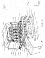
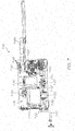
- Figs. 1A to 1D illustrate a printing system 1-1000 according to a first embodiment of the present invention.
- the printing system 1-1000 has a print head chassis 1-10 for holding multiple print head cartridges 1-20a, 1-20b, 1-20c, 1-20d, 1-20e (see Fig. ID) and corresponding print head controller modules 1-25a, 1-25b, 1-25c, 1-25d, 1-25e.
- the figures illustrate only one print head cartridge 1-20a.
- reference numerals 1-20b, 1-20c, 1-20d, and 1-20e are used to indicate where the remaining print head cartridges are located.
- each print head cartridge 1-20a-e spans a width of the print media 1-200.
- the five print head cartridges 1-20a-e are positioned one after another along a direction of print media propagation, that is, in the X-direction as indicated by the axes in Fig. 1A .
- Each print head cartridge 1-20a-e is connected to respective monochrome ink supply modules 1-90a, 1-90b, 1-90c, 1-90d, 1-90e.
- Each print head cartridge 1-20a-e prints ink of a single colour/property only.
- each print head cartridge 1-20a-e prints one of Cyan, Magenta, Yellow, Black, and a spot colour (e.g. Khaki), however, any combination of colours may be printed by the print head cartridges 1-20a-e.
- the disclosed invention is not limited to only five print head cartridges, and may comprise any number from two or more print head cartridges. Further, for simplicity and conciseness of description, while the fluids ejected by the print head cartridges 1-20a-e are referred to herein as "inks", it is to be understood that the terms “ink” and “inks” refer to any fluid that may be ejected by the print head cartridges 1-20a-e including a fixative, a glue or other bonding substance, fluidic semiconductor material, and the like.
- colour is used to refer broadly to the properties of the fluids ejected by the print head cartridges 1-20a-e, rather than strictly to a colour in the human visible spectrum.
- a fixative may be referred to as an "ink” in the present disclosure, and may also be referred to as having a "colour” in the sense that the fixative has a property that distinguishes it from the other inks.
- a print head cartridge that receives monochromatic ink refers to a print head cartridge that receives ink/fluid of only one colour/property", such as cyan ink, magenta ink, yellow ink, black ink, infrared ink, a fixative, a glue, a semiconductor material in fluid state, and so forth.
- the print head cartridges 1-20a-e are stand-alone cartridges that are individually removable from the print head chassis 1-10.
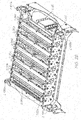
- a print head cartridge 1-20 is illustrated in greater detail in Fig. 12 .
- the print head cartridge 1-20 comprises a plurality of print head tiles 12-10 arranged end-to-end along a length (i.e. Z-axis of Fig. 1A ) of the print head cartridge.
- Fig. 12 illustrates 11 print head tiles 12-10 arranged end-to-end to form the page width print head cartridge 1-20 however it should be understood that more or less than 11 print head tiles may be employed, as necessary to span a width of the print media 1-200.
- Each print head tile 12-10 has a plurality of logical rows 12-20.
- each print head tile 12-10 is illustrated with 5 logical rows 12-20, however a lesser or greater number of logical rows may be provided.
- Each logical row 12-20 is divided into a pair of sub-rows 12-30, 12-40, which sub-rows are offset with respect to each other along a length (i.e. Z-axis of Fig. 1A ) of the print head cartridge 1-20.
- the first sub-row 12-30 of each row 12-20 prints odd numbered dots for a line on a page, whilst the second sub-row 12-40 prints even numbered dots for the same line on the page, or vice versa.
- a logical row 12-20 shows one logical row 12-20 as being comprised of two adjacent sub-rows 12-30, 12-40, a logical row may in fact be comprised of any even dot printing sub-row 12-30 and any odd dot printing sub-row 12-40, not necessarily adjacent to each other
- the print head cartridges 1-20a-e are spaced from each other along a width of the printing system 1-1000 (i.e. X-axis of Fig. 1A ), that is, along a direction of print media propagation. Compared to the size of the dots printed by the print head cartridges 1-20a-e, the spacing between the print head cartridges 1-20a-e is very large, and measured in standard units of length (i.e. mm, cm, inches, etc.). In one embodiment, the print head cartridges 1-20a-e are spaced at 8 cm intervals from each other.
- the print head chassis 1-10 is attached via scissor guide 1-40 to the printer main frame 1-50.
- the scissor guide 1-40 and a lift mechanism 1-60, together with a pair of wires (not shown) interconnecting the scissor guide 1-40 and the lift mechanism 1-60 actuate the print head chassis 1-10 between a printing position, a transition position, and a maintenance position.
- Fig. 1A illustrates the printing system 1-1000 while in the transition position.
- the print head chassis 1-10 In the transition position, the print head chassis 1-10 is held at a height, relative to the platen 1-70, that allows for the maintenance chassis 1-80 to be manoeuvred under the print head chassis 1-10 without being interfered with by the print head chassis 1-10.
- the transition position allows the maintenance chassis 1-80 to retract to and from a storage position under the ink supply modules 1-90a-e, and an operational position under the print head chassis 1-10.
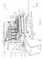
- Fig. 1B illustrates the printing system 1-1000 while in the printing position.
- the printer main frame 1-50 is illustrate with one side thereof removed, to more clearly show the components housed therein.
- the print head chassis 1-10 is positioned in close proximity to the platen 1-70 to enable printing by the print head cartridges 1-20a-e onto the print media 1-200 propagating across the platen 1-70.
- Fig. 1C illustrates the printing system 1-1000 while in the maintenance position.
- the print head chassis 1-10 In the maintenance position, the print head chassis 1-10 is positioned some distance above the platen 1-70, and the maintenance chassis 1-80 is positioned in an operational position interposed between the platen 1-70 and the print head chassis 1-10. In the maintenance position, the print head 1-10 is supported by the maintenance chassis 1-80.
- the platen 1-70 is part of the printing system 1-1000. In other aspects, however, the printing system 1-1000 does not include the platen 1-70, and the platen 1-70 is instead configured and designed by a third party and/or an end-user. In the first embodiment, however, the platen 1-70 is provided with positioning pins 1-100a, 1-100b, 1-100c, 1-100d (see also Fig. 8A ) which couple with pin bushes 2-100a, 2-100b, 2-100c, 2-100d on an underside of the print head chassis 1-10 (see also Fig. 2B ). The positioning pins 1-100a, 1-100b, 1-100c, 1-100d, as illustrated in Fig.
- the platen 1-70 includes a source of the print media 1-200, and a feed mechanism 1-210 for feeding the print media 1-200 across a printing surface 1-220 of the platen 1-70.
- An encoder wheel 1-230 is included with the platen 1-70 for measuring a speed of the print media 1-200 as it is propagated across the platen 1-70. The speed measured by the encoder wheel 1-230 is used to time and synchronize an operation of the print head cartridges 1-20a-e.
- Figs. 2A and 2B illustrate in greater detail the print head chassis 1-10 and the print head cartridges 1-20a-e. In Figs. 2A and 2B , only one printhead cartridge 1-20a is again shown for purposes of clarity.
- the print head controller modules 1-25a-e, and the print head cartridges 1-20a-e are equally spaced apart in the print head chassis 1-10.
- Each print head cartridge 1-20a-e is removably engaged with the print head chassis 1-10 via corresponding locking tabs 2-40.
- the print head controller modules 1-25a-e are engaged with the print head chassis 1-10 so as to be pivotable towards and away from a respective print head cartridge 1-20a-e through actuation of respective locking mechanisms 2-10a, 2-10b, 2-10c, 2-10d, 2-10e.
- Each print head controller module 1-25a-e electrically engages with a respective print head cartridge 1-20a-e by pivoting towards the respective print head cartridge 1-20a-e such that a row of electrical connectors 1-500 (see detailed cutout) on each print head controller module 1-25a-e pushes against the respective print head cartridge 1-20a-e.
- Each print head controller module 1-25a-e is locked in electrical engagement with respective print head cartridges 1-20a-e by locking mechanisms 2-10a, 2-10b, 2-10c, 2-10d, and 2-10e.
- an ink aerosol filter 2-20 is provided at one end of the chassis to collect and filter aerosol particles of ink arising from each print head cartridge 1-20a-e.
- the ink aerosol filter 2-20 is connected via hoses (not shown) to ventilation outlets 2-30a, 2-30b, 2-30c, 2-30d, 2-30e, 2-30f (see also Fig. 2C ) respectively connected to suction slits 2-35a, 2-35b, 2-35c, 2-35d, 2-35e, 2-35f (see Fig. 2B ) provided in the vicinity of each print head cartridge 1-20a-e.
- the aerosol filter 2-20 includes inlet ports 2-25 to which the hoses from respective ventilation outlets 2-30a, 2-30b, 2-30c, 2-30d, 2-30e, 2-30f connect, and an outlet port 2-28 which preferably connects to a further filter such as a HEPA filter, and then to a suction device.
- a further filter such as a HEPA filter
- Pin bushes 2-100a, 2-100b, 2-100c, 2-100d are provided on each of the four bottom corners of the print head chassis 1-10.
- Pin bushes 2-100a, 2-100b, 2-100c, 2-100d support the print head chassis 1-10 (as described in greater detail below), and further provide an aligning feature for ensuring proper alignment of the print head chassis 1-10 with the maintenance chassis 1-80 and the platen 1-70.
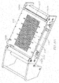
- Figs. 3A and 3B illustrate the maintenance chassis 1-80 in greater detail.
- the maintenance chassis 1-80 includes print head maintenance cradles 3-20a, 3-20b, 3-20c, 3-20d, 3-20e.
- Each print head maintenance cradle includes a capper 3-25 and a cleaner 3-27.
- the capper 3-25 provides the function of sealing a print head of a print head cartridge 1-20a-e when the print head cartridge is not in used, and to also serve as a spittoon in which ink from the print head cartridge is ejected for priming and cleaning purposes.
- Positioning pins 3-50a, 3-50b, 3-50c, 3-50d are provided at each corner of the maintenance chassis 1-80.
- Positioning pins 3-50a, 3-50b, 3-50c, 3-50d are similar to the positioning pins 1-100a, 1-100b, 1-100c, 1-100d on the platen 1-70 in that they are for coupling with pin bushes 2-100a, 2-100b, 2-100c, 2-100d provided on an underside of the print head chassis 1-10.
- the positioning pins 3-50a, 3-50b, 3-50c, 3-50d preferably have a rounded, dome head.
- the maintenance chassis 1-80 includes a maintenance chassis sub-frame 3-10 (see also Fig. 4A ) on which the print head maintenance cradles 3-20a-e are supported, and a maintenance chassis main frame 4-50 within which the maintenance chassis sub-frame 3-10 resides.
- the maintenance chassis sub-frame 3-10 is movable within the maintenance chassis main frame 4-50.
- a sub-frame movement mechanism 3-40 (see Fig. 3A ) is provided on the maintenance chassis main frame 4-50 and connected to the maintenance chassis sub-frame 3-10 by a connection member 3-30 to effect movement of the maintenance chassis sub-frame 3-10, and hence the print head maintenance cradles 3-20a-e, with respect to the maintenance chassis main frame 4-50.
- the maintenance chassis sub-frame 3-10 is moved with respect to the maintenance chassis main frame 4-50 to allow either the capper 3-25 or the cleaner 3-27 to be aligned with the print head cartridges 1-20a-e.
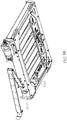
- Figs. 4A and 4B illustrates the maintenance chassis sub-frame 3-10 in greater detail.
- Fig. 4C illustrates the maintenance chassis main frame 4-50 in greater detail.
- the maintenance chassis sub-frame 3-10 has a pair of rails 4-10 which engage with rail supports 4-15 of the maintenance chassis main frame 4-50 allowing the maintenance chassis sub-frame 3-10 to slide within the maintenance chassis main frame 4-50.
- Each print head maintenance cradle 3-20a-e is supported between the pair of rails 4-10, and spaced equally apart with a pitch matching that of the spacing between the print head cartridges 1-20a-e, as required to either clean or cap the print head cartridges 1-20a-3.
- the cleaner 3-27 includes a first roller 3-29 of a microfiber material and a second roller 3-28 made of stainless steel or other suitable hard material.
- the first roller 3-29 provides the function of wiping a print head and wicking ink therefrom, whilst the second roller 3-28 serves the function of pressing against the first roller 3-29 to cause ink soaked thereinto to be squeezed out.
- a wiper blade 3-24 is also included in each print head maintenance cradle 3-20a-e to scrape from the second roller 3-28 any ink that is squeezed out from the first roller 3-29.
- Each print head maintenance cradle 3-20a-e further includes a roller driver 3-30 for driving the first and second rollers 3-28, 3-29, and a sump 3-40 for collecting ink received by the cleaner 3-27 and the capper 3-25.
- the sump 3-40 has a sloping floor 3-45 (see Fig. 5B ) having a lowest point at one end of the maintenance cradle 3-20a-e.
- the floor of the sump 3-40 has a drain hole 3-48 from which ink collected in the sump drains.
- the drain holes 3-48 of each maintenance cradle 3-20a-e drain into an ink collection channel 3-60 (see Fig. 4C ) provided along one side of the maintenance chassis main frame 4-50.
- the ink collection channel 3-60 connects with a series of channels provided in the printer main frame 1-50 to empty into a waste ink tank 6-30 (see Fig. 6 ).
- the maintenance chassis 1-80 is provided with rollers 3-70 (see Fig. 4C ) on two opposing sides of the chassis.
- the rollers 3-70 allow the maintenance chassis 1-80 to extend and retract between a storage position (as shown in Fig. 1B ) and an operational position (as shown in Figs. 1A and 1C ).
- a motor 3-80 attached to the maintenance chassis main frame 4-50 engages with a toothed rack 3-90 on the printer main frame 1-50 to translate the maintenance chassis 1-80 between the storage position and the operational position.
- Fig. 6 provides a view of the printing system 1-1000 from the rear. For clarity of illustration, all but one ink blade 1-90e is removed from respective ink blade docking slots. The maintenance chassis 1-80 is also shown transitioning to an operational position under the print head chassis 1-10.
- the waste ink tank 6-30 is secured to a floor of the main chassis 1-50. As previously described, the waste ink tank 6-30 stores ink received by the capper 3-25 as a result of a purging or priming operation, and ink received by cleaner 3-27 as a result of cleaning the print head cartridges 1-20a-e.
- Each ink blade 1-90a-e is slidable in a rearward direction (i.e. negative Z-direction of axis on Fig. 1A ) to remove the ink blade from the main chassis 1-50. In this manner, convenient exchanging of ink blades to change a colour to be printed by a particular print head is facilitated.
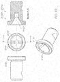
- Fig. 7 illustrates one of the ink blades 1-90a-e in greater detail.
- the ink blade depicted is given reference numeral 7-10.
- the ink blade 7-10 is provided as a blade chassis 7-15 on which the components of the ink blade 7-10 are mounted and supported.
- the blade chassis 7-15 defines a back plate 7-20 on which an ink inlet 7-30 is provided.
- the ink inlet 7-30 receives ink from an external bulk ink source (not shown) via an inlet hose 7-40 and communicates the ink to an input 7-60 of a bulk ink pump 7-80.
- An output 7-70 of the bulk ink pump 7-80 connects to a bulk ink input 7-90 of an intermediate reservoir 7-50.
- An ink filter 7-100 is provided downstream from the intermediate reservoir 7-50 and connects to an ink manifold 7-110.
- the ink manifold 7-110 is connected to a pinch valve 7-120, which in turn communicates ink to the print head.
- a hose carrier 7-130 is provided to support the hoses (not shown) connecting the pinch valve 7-120 to the print head.
- Return hoses (not shown) for returning ink from the print head to the intermediate reservoir 7-50 may also be supported on the hose carrier 7-130.
- the return hoses (not shown) from the print head connect to a printing ink pump 7-140, which in turn connects back to the intermediate reservoir 7-50.
- the printing ink pump 7-140 is down stream from the print head and essentially sucks in through the print head, as opposed to pushing ink to the print head.
- a negative pressure pump 7-150 is further provided to maintain a negative pressure in the intermediate reservoir 7-50.
- the ink manifold 7-110 defines a plurality of outlets 7-85 which all connect ultimately to a single print head cartridge 1-20a, 1-20b, 1-20c, 1-20d, or 1-20e.
- each print head cartridge 1-20a-e is supplied with ink from a single ink blade 7-10, and hence monochromatically supplied with ink of a single colour.
- the colour of ink supplied to a print head cartridge 1-20a-e is changeable by replacing the ink blade 7-10 connected thereto, and performing a suitable re-priming process to flush existing ink from the print head cartridge 1-20a-e and priming the print head cartridge 1-20a-e with new ink.
- an entire print head cartridge 1-20a-e is replaced when exchanging ink blades 7-10, whereby the colours printed by the printing system 1-1000 may be rapidly changed to suit different print jobs.
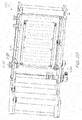
- Figs. 8A and 8B show front and rear perspective views, respectively, of the platen 1-70.
- the platen 1-70 is part of the printing system 1-1000 in some aspects. In other aspects, the platen 1-70 is provided by a third party or the end user, and configured to work with the printing system 1-70.
- the platen 1-70 is a vacuum platen and allows the provision of a suction force through the platen surface 1-220 to assist in maintaining a print media 1-200 traversing across the surface 1-220 of the platen 1-70 flat against the surface 1-220.
- the surface 1-220 of the platen 1-70 defines depressions 8-10.
- Suction holes 8-15 are defined in each depression 8-10, which pass through the surface 1-220 of the platen 1-70 to an opposite side.
- a vacuum box may be attached to an underside of the platen 1-70, in which one or more suction devices are provided to generate a suction force downwards through the platen 1-70.
- the positioning pins 1-100a, 1-100b, 1-100c, 1-100d are supported on an adjustment cam system 8-20, which allows for the height of the positioning pins 1-100a, 1-100b, 1-100c, 1-100d to be adjusted via adjustment knob 8-30.
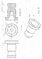
- Figs. 9 , 10 , and 11 illustrate in detail the pin bushes 2-100a, 2-100b, 2-100c, 1-120d located on an underside of the print head chassis 1-10.
- Pin bush 2-100a located at a front-right under-corner of the print head chassis 1-10 when in an operative position is a location bush having a shape and configuration as illustrated in Fig. 9 .
- the location bush illustrated in Fig. 9 is given the reference numeral of 9-100.
- the location bush 9-100 has a circular head 9-10.
- the circular head 9-10 defines a circular-conical depression 9-20.
- the circular-conical depression 9-20 is adapted to receive positioning pins 1-100a and 3-50a therein. Due to the circular-conical configuration of the depression 9-20 and the rounded head of positioning pins 1-100a and 3-50a, the pins 1-100a and 3-50a always couple with the location bush 9-100 in a consistent and exact engagement.
- Pin bush 2-100b located at a front-left under-corner of the print head chassis 1-10, when in an operative position, is a slotted location bush having a shape and configuration as illustrated in Fig. 10 .
- the location bush illustrated in Fig. 10 is given the reference numeral of 10-100.
- the slotted location bush 10-100 has a circular head 10-10.
- the circular head 10-10 defines an oval-conical depression 10-20.
- the oval-conical depression 10-20 is adapted to receive positioning pins 1-100b and 3-50b therein.
- the oval-conical configuration of the depression 10-20 allows one degree of freedom for the pins 1-200b and 3-50b received therein.
- the axis of freedom is in the X-direction of Fig. 1A , that is, parallel to the width of the printing system 1-1000 (i.e. parallel to a direction of print media propagation).
- the slotted location bush 10-100 allows the front-left corner of the print head chassis 1-10 one degree of freedom along the X-axis of Fig. 1A , that is along the direction parallel to a width of the printing system 1-1000 (i.e. parallel to a direction of print media propagation), but consistently aligns the corner along the Z-axis, that is, normal to a width of the printing system 1-1000 (i.e. normal to a direction of print media propagation).
- This allows for some degree of variation in the manufacture and/or location of the pins 1-100b and 3-50b and the pin bush 2-100b. In this manner, consistent and stable support of the print head chassis 1-20 and the maintenance chassis 1-80 is less sensitive to the exactness of manufacture and location of the positioning pins 1-100b and 3-50b, and the pin bush 2-100b.
- the location bush 10-100 which allows for no freedom of movement in the X-Y plane for the positioning pins 1-100a and 3-50a received therein, hence determines the base/reference location of the print head chassis 1-10 with respect to the platen 1-70 and the maintenance chassis 1-80. Together with the slotted location bush 10-100, which allows freedom of movement along the X axis but not the Z axis, and combined with the fact that the print head chassis 1-10 is a rigid structure, consistent alignment of the print head chassis 1-10 in the X-Z plane is achieved. The remaining two corners of the print head chassis 1-10 and the maintenance chassis 1-80 are positioned with respect to the positioning determined by the location bush 9-100 and slotted location bush 10-100.
- the pin bushes 2-100c and 2-100d located at a rear-left and rear-right under-corners of the print head chassis 1-10 are flat pin bushes having a shape and configuration as illustrated in Fig. 11 .
- the flat pin bushes illustrated in Fig. 11 is given the reference numeral of 11-100.
- the flat pin bush 11-100 has a circular head 11-10, but unlike the location bush 9-100 and the slotted location bush 10-100, does not have a depression defined into a top of the head 11-10. Instead, the head 11-10 presents a solid, flat surface 11-20.
- the head 11-10 of the flat pin bush 11-100 used on the print head chassis as rear-left and rear-right bushes 2-100c, 2-100d may be formed with a flat head as opposed to a depression because further positioning of the print head chassis 1-10 with respect to the platen 1-70 or to the maintenance chassis 1-80 is not necessary.
- the location bush 9-100 and the slotted location bush 10-100 provide all necessary alignment of the print head chassis 1-10 with respect to the platen 1-70 and the maintenance chassis 1-80.
- Fig. 12 illustrates a print head chassis 1-10 according to which ventilation outlets 2-30a, 2-30b, 2-30c, 2-30d (see Fig. 2C ) feed into a pair of common aerosol extraction rails 20-10a, 20-10b via connectors 20-20a, 20-20b, 20-20c, 20-20d.
- the common aerosol extraction rails 20-10a, 20-10b feed into the aerosol filter 2-20.
- the use of the common aerosol extraction rails 20-10a, 20-10b eliminates the need for individual hoses connecting each of the ventilation outlets 2-30a, 2-30b, 2-30c, 2-30d, 2-30e, 2-30f to the aerosol filter 2-20.
- the print head chassis 1-10 is rendered less cluttered, and permits easier user access to and manipulation of the elements supported in the print head chassis 1-10. Moreover, ventilation of the print head chassis 1-10 is noticeably improved.
- Figures 13 and 13A discloses further elements.
- the print head chassis 1-10 is provided with support arms 21-10a, 21-10b, 21-10c, 21-10d. Support arms 21-10a, 21-10b, 21-10c, 21-10d are attached respectively at each corner of the print head chassis 1-10.
- Each support arm 21-10a, 21-10b, 21-10c, 21-10d is respectively fixed to a corner of the print head chassis 1-10 and extends above the print head chassis 1-10 in a crane-like manner, so as to overhang the edges of the print head chassis 1-10.
- Each support arm 21-10a, 21-10b, 21-10c, 21-10d defines a support fixture 21-15a, 21-15b, 21-15c, 21-15d at which there is provided a positioning pin 1-100a, 1-100b, 1-100c, 1-100d.
- the positioning pins 1-100a, 1-100b, 1-100c, 1-100d are each engaged with pin height adjusters 21-20a, 21-20b, 21-20c, 21-20d which adjust the amount by which each positioning pin 1-100a, 1-100b, 1-100c, 1-100d protrudes from the support fixtures 21-15a, 21-15b, 21-15c, 21-15d.
- the print head chassis 1-10 is supported from a pair of gantries 21-30a, 21-30b via the positioning pins 1-100a, 1-100b, 1-100c, 1-100d of the support arms 21-10a, 21-10b, 21-10c, 21-10d.
- the gantries 21-30a, 21-30b are provided running above and across the platen 1-70 to provide a framework suspended over the platen 1-70 upon which the printing system 1-1000 is supported
- the gantries 21-30a, 21-30b may be provided as part of the printing system 1-1000, or may be provided by 3 rd party providers to suit specific requirements.
- the printing system 1-1000 includes a mounting frame 21-40a, 21-40b secured to the printer main frame 1-50.
- Each mounting frame 21-40a, 21-40b includes a pair of pin bushes 2-100a, 2-100b, 2-100c, 2-100d.
- the pin bushes 2-100a, 2-100b, 2-100c, 2-100d provided on each mounting frame 21-40a, 21-40b are identical to those used according to the invention.
- the mounting frame 21-40a, 21-40b allows the printing system 1-1000 to be supported on the gantries 21-30a, 21-30b, for example by way of a complementary ridge and groove coupling between the mounting frame 21-40a, 21-40b and the gantries 21-30a, 21-30b.
- the pin bushes 2-100a, 2-100b, 2-100c, 2-100d provided on the mounting frame 21-40a, 21-40b of each gantry 21-30a, 21-30b receive the positioning pins 1-100a, 1-100b, 1-100c, 1-100d of the support arms 21-10a, 21-10b, 21-10c, 21-10d in like manner to that described above to provide consistent and stable support for the print head chassis 1-10 with respect to the platen 1-70.
- Pin height adjuster 21-20a, 21-20b, 21-20c, 21-20d allow the amount by which each positioning pin 1-100a, 1-100b, 1-100c, 1-100d protrudes to be adjusted, thereby allowing the height of the print head chassis 1-10 with respect to the platen 1-70 to be adjusted.
- the print head chassis 1-10 is supported on positioning pins protruding upwards from the platen 1-70. Having positioning pins protruding from the platen 1-70 restricts the width of the print media upon which the printing system 1-1000 can print, since any print media that is used must fit within the bounds of the protruding positioning pins.
- the print head chassis 1-10 is supported from gantries that are suspended above the platen 1-70.
- the platen 1-70 is free of protrusions which limit the width of the print media passing thereon.
- the printing system 1-1000 therefore supports printing on print media of any width.
- Each gantries 21-30a, 21-30a is provided with a pair of positioning grooves 21-50a, 21-50b which respectively couple with a corresponding ridge on the mounting frames 21-40a, 21-40b of two adjacent printing systems 1-1000.
- multiple printing systems 1-1000 are arranged side-by-side, and preferably offset with each other, across a width of the print media to enable printing on a wide-format print media.
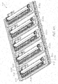
- Figs. 14 to 16 illustrate a platen 1-70.
- the platen 1-70 springs 22-10 (see Fig. 16 ) to bias positioning pins 1-100a, 1-100b, 1-100c, 1-100d upwards, and utilizes clamping plates 22-20 and clamping screws 22-30 to clamp the positioning pins 1-100a, 1-100b, 1-100c, 1-100d at a suitable height.
- the use of independent spring biased positioning pins 1-100a, 1-100b, 1-100c, 1-100d at each corner of the platen 1-70 allows the height of each positioning pin 1-100a, 1-100b, 1-100c, 1-100d to be adjusted independently of the other positioning pins.
- each positioning pin 1-100a, 1-100b, 1-100c, 1-100d is mechanically simpler than the cammed system, involving less mechanical parts and movement and greater flexibility.
- a desired height for each positioning pin 1-100a, 1-100b, 1-100c, 1-100d is obtained by allowing each spring 22-10 to bias a respective positioning pin 1-100a, 1-100b, 1-100c, 1-100d upwards to the desired height, and then clamping the clamping plates 22-20 against the positioning pin 1-100a, 1-100b, 1-100c, 1-100d to lock the positioning pin 1-100a, 1-100b, 1-100c, 1-100d in place at the desired height.
- Figs. 17 and 18 illustrates an ink drainage system of the printing system 1-1000.
- the ink collection channel 3-60 (see Fig. 4C ) of the maintenance chassis 1-80 is provided with a drainage port 25-10.
- the waste ink tank 6-30 is replaced with a flat waste ink tray 25-20 provided on a base of the printing system 1-1000.
- the flat waste ink tray 25-20 is lined with an absorbent material 25-30 to capture the waste ink.
- the flat waste ink tray 25-20 is sized to ensure that regardless of the positioning of the maintenance chassis 1-80 (for example, whether the printing system is in the printing position, transition position, or maintenance position), the flat waste ink tray 25-20 captures ink from the drainage port 25-10.
- the printing system 1-1000 is made shorter in height, and more important, has no components which extend below the print head tiles 12-10 of the print head cartridges 1-20a, 1-20b, 1-20c, 1-20d, 1-20e. That is, the print head tiles 12-10 from which ink is ejected are effectively the lowest, or equal lowest, point of the printing system 1-1000 and are closest, or equal closest, to the platen 1-70, in contrast with the embodiment illustrated in Fig. 6 , for example, where the waste ink tank 6-30 is substantially below a surface of the platen 1-70..
- the printing system 1-1000 in having a waste ink tank and other components that are substantially lower than the print head chassis 1-10 in the printing position, prevents the printing system 1-1000 from being entirely suspended above the platen 1-70, and hence prevent the printing system 1-1000 from being used with multiple printing systems 1-1000 side-by-side to print on print media wider than the printing system 1-1000.
- the printing system 1-1000 has no component protruding beyond the print head tiles 12-10 towards the platen 1-70, and may therefore be positioned in any location/position above a platen of any size.
- the flat waste ink tank 25-20 is sized to preferably match a footprint of the maintenance chassis 1-80.
- the flat waste ink tray 25-20 is sized and shaped so as to have a portion thereof always under the drainage port 25-10, regardless of the position the maintenance chassis 1-80 is currently in (e.g. storage position, operational position, or in between a storage and operational position).
- the size and shape of the flat waste ink tray 25-20 must therefore cover at least a locus of movement of the drainage port 25-10 as the maintenance chassis 1-80 moves between the operational and storage port.
- the printing system 1-1000 is illustrated in the maintenance position.
- the print head chassis 1-10 is supported on the maintenance chassis 1-80.
- the pins 3-50a, 3-50b, 3-50c, 3-50d located at the four corners on the top of the maintenance chassis 1-80 support the location bush 2-100a, the slotted location bush 2-100b, and flat pin bushes 2-100c, 2-100d respectively.
- the print head cartridges 1-20a-e are engaged with either the cappers 3-25 or the cleaners 3-27 of the maintenance chassis 1-80.
- the print head cartridges 1-20a-e are preferably engaged with the cappers 3-25 to prevent the print head cartridges 1-20a-e from drying out and collecting contaminants, and to generally prevent damage thereto.
- the print head chassis 1-10 is first lifted upwards in the Y-direction by the lift mechanism 1-60 to a height, for example, of that of the transition position illustrated in Fig. 1A .
- the sub-frame movement mechanism 3-40 translates the maintenance chassis sub-frame 3-10 in the X-direction, such that the cappers 3-25 are moved out of alignment with the print head cartridges 1-20a-e and the cleaners 3-27 are moved into alignment with the print head cartridges 1-20a-e.
- the print head chassis 1-10 is then lowered back onto the maintenance chassis 1-80 into the maintenance position illustrated in Fig. 1C .
- the location bush 2-100a on the front-right under-corner of the print head chassis 1-10 comes into contact with the pin 3-50a on a front-right upper-corner of the maintenance chassis 1-80.
- the circular-conical depression 9-20 of the location bush 2-100a receives the pin 3-50a, and in doing so aligns the front-right corner of the print head chassis 1-10 with respect to the maintenance chassis 1-80 along the X-axis and Z-axis.
- the slotted location bush 2-100b on the front-left under-corner of the print head chassis 1-10 comes into contact with the pin 3-50b on the front-left upper-corner of the maintenance chassis 1-80.
- the oval-conical depression 10-20 of the slotted location bush 2-100b receives the pin 3-50b, and in doing so aligns the front-left corner of the print head chassis 1-10 with respect to the maintenance chassis 1-80 along the Z-axis.
- the front-left corner of the print head chassis 1-10 is already aligned along the X-axis by virtue of the location bush 2-100a being fixed in the X-Z plane, and further by virtue of the fact that the print head chassis 1-10 is a rigid structure.
- the print head chassis 1-10 With the front-right and front-left corners of the print head chassis 1-10 aligned and fixed along the X and Z axes, the print head chassis 1-10 as a whole, in being a rigid structure, is aligned with the maintenance chassis 1-80.
- Flat bushes 2-100c and 2-100d at the rear-left and rear-right lower corners of the print head chassis 1-10 may be simply supported by pins 3-50c and 3-50d respectively of the print head maintenance chassis 1-80 without requiring location slots/depressions such as present in location bush 2-100a and slotted location bush 2-100b.
- the print head cartridges 1-20a-e are positioned in contact with respective first rollers 3-29 of the cleaners 3-27, which first rollers 3-29 are made of the micro fiber material for wiping across a print head of the print head cartridges 1-20a-e.
- the maintenance chassis 1-80 needs to be retracted into the printer main frame 1-50 and the print head chassis 1-10 accurately lowered and positioned with respect to the platen 1-70. Accordingly, the print head chassis 1-10 is first lifted by the lifting mechanism 1-60 to the transition position illustrated in Fig. 1A .
- the print head chassis 1-10 is not supported by the maintenance chassis 1-80, and the print head cartridges 1-20a-e are disengage from the maintenance cradles 3-20a-e.
- the maintenance chassis 1-80 is hence free to be retracted back into the printer main frame 1-50, as shown in Fig. 1B .
- the printer head chassis 1-10 With the maintenance chassis 1-80 retracted back into the printer main frame 1-50, the printer head chassis 1-10 is free to be lowered towards the platen 1-70. Accordingly, the lifting mechanism 1-60 lowers the print head chassis 1-10 towards the platen 1-70.
- the location bush 2-100a on the front-right bottom corner of the print head chassis 1-10 comes into contact with the pin 1-100a on a front right corner of the platen 1-70.
- the print head chassis 1-10 is aligned to the platen 1-70 by the receipt of the pin 1-100a into the circular-conical depression 9-20 of the locating bush -200a. In this manner, the front-right corner of the print head chassis 1-10 is aligned with respect to the platen 1-70 along the X-axis and Z-axis.
- the slotted location bush 2-100b on the front-left bottom corner of the print head chassis 1-10 comes into contact with the pin 1-100b on the front-left upper corner of the platen 1-70.
- the oval-conical depression 10-20 of the slotted locating bush 2-100b receives the pin 1-100b, and in doing so aligns the front-left corner of the print head chassis 1-10 with respect to the platen 1-70 along the Z-axis.
- the front-left corner of the print head chassis 1-10 is already aligned along the X-axis by virtue of the location bush 2-100a being fixed in the X-Z plane, and further by virtue of the fact that the print head chassis 1-10 is a rigid structure.
- the print head chassis 1-10 With the front-right and front-left corners of the print head chassis 1-10 aligned and fixed along the X and Z axes, the print head chassis 1-10 as a whole, in being a rigid structure, is aligned with the platen 1-70.
- Flat bushes 2-100c and 2-100d at the rear-left and rear-right lower corners of the print head chassis 1-10 may be simply supported by pins 1-100c and 1-100d respectively of the platen 1-70 without need for locating slots/depressions such as those defined in locating bush 2-100a and slotted locating bush 2-100b.
- alignment of the print head cartridges 1-20a-e with respect to the maintenance cradles 3-20a-e is also consistently achieved despite repeated movement of the print head chassis 1-20 towards and away from the maintenance chassis 1-80, and movement of the maintenance chassis 1-80 to and from a retracted position within the printer main frame 1-50.
- the relative spacing between the print head cartridges 1-20a-e is kept consistent since the print head cartridges 1-20a-e are not moved with respect to each other. Rather, the print head cartridges 1-20a-e are moved as a unitary set by moving the print head chassis 1-10. The same applies to the maintenance cradles 3-20a-e, in being moved as a unitary set by moving the maintenance chassis 1-80 rather than individual cradles 3-20a-e.
- any loss of accuracy and consistency in the alignments of the print head chassis 1-10, maintenance chassis 1-80, and platen 1-70 with respect to each other is caused mainly by a wearing of the positioning pins 1-100a, 1-100b, 1-100c, 1-100d, 3-50a, 3-50b, 3-50c, 3-50d and bushes 2-100a, 2-100b, 2-100c, 2-100d.
- the wearing of such components is not considered an issue over the lifetime of the printing system 1-1000.
- the head chassis 1-10 is lowered until the positioning pins 1-100a, 1-100b, 1-100c, 1-100d of each support arm 21-10a, 21-10b, 21-10c, 21-10d are received by the pin bushes 2-100a, 2-100b, 2-100c, 2-100d on the mounting frames 21-40a, 21-40b.
- the interaction of the positioning pins 1-100a, 1-100b, 1-100c, 1-100d with the pin bushes 2-100a, 2-100b, 2-100c, 2-100d is identical to that described above for the mechanical operation of the first embodiment.
- pin height adjusters 21-20a, 21-20b, 21-20c, 21-20d may be manipulated as necessary to adjust the height of the print head chassis 1-10 from the platen 1-70 at each corner.
- the printing system 1-1000 of the present disclosure utilizes multiple print head cartridges 1-20a-e, each printing a single colour.
- Each print head cartridge 1-20a-e is separated from a neighbouring print head cartridge in the direction of print media propagations (i.e. X-axis in Fig. 1A ) and by a distance that is significantly larger than a width of a nozzle or a dot pitch. This distance is measureable in centimetres, and in one example, the print head cartridges 1-20a-e have a separation pitch of around 8 centimetres.
- One print head cartridge 1-20 as shown in Fig. 12 and as previously described, comprises of a number of print head tiles arranged end to end to span the width of the print media. In Fig.
- the print head cartridge 1-20 is exemplarily illustrated with 11 print head tiles 12-10 arranged end to end.
- Each print head tile has a number of logical rows 12-20 of nozzles.
- each print head tile 12-10 is exemplarily illustrated with 5 logical rows of nozzles.
- SPHC print head cartridge
- all of the 5 logical rows of nozzles eject the same coloured ink.
- Each logical row of nozzles is separated into a pair of sub-rows 12-30, 12-40, one sub-row for printing even dots and the other sub-row for printing odd dots. Whilst Fig.
- logical row 12 shows one logical row 12-20 as being comprised of two adjacent sub-rows 12-30, 12-40, a logical row may in fact be comprised of any even dot printing sub-row 12-30 and any odd dot printing sub-row 12-40, not necessarily adjacent to each other.
- a nozzle of one logical row of one print head tile has to eject a drop of ink in very close vicinity (and preferably on top) of a corresponding nozzle of a corresponding row of a corresponding print head tile of another print head cartridge that may be around 32 cm away.
- a multiple print head cartridge (MPHC) system must ensure that the print head tiles making up each print head cartridge are in alignment with each other.
- SPHC pagewidth print head cartridge
- MPHC multiple print head cartridge
- the positioning of the print media with respect to the print head cartridge in an SPHC system and a scanning-type system, from the perspective of the nozzles, can therefore be seen as relatively consistent.
- the shifting and wobbling of the print media become significant and require non-trivial compensation, since a first print head cartridge may be separated from the last print head cartridge by around 32 cm.
- the amount of possible aberrant print media movement as the print media is propagated a distance of 32 cm is quite significant.
- a view of the print media as seen by a nozzle printing Cyan in a Cyan print head cartridge may be vastly different to a view of the print media seen by a nozzle printing Yellow in the Yellow print head cartridge, which could be around 32 centimetres away.
- a shifting/wobbling of the print media as the print media is fed along the platen which conventionally can be ignored due to either the closeness of the different coloured nozzles (for an SPHC system) or the small distance the paper moves between printing of swathes (for a scanning-type system), can no longer be ignored.
- a 2-D Vernier calibration method is performed.
- Fig. 13 illustrates a 2-D Vernier calibration map 13-100.
- the 2-D Vernier calibration map 13-100 comprises rows 13-50, 13-60, 13-70, 13-80 of horizontally printed Vernier patterns 13-10 printed across the map.
- the 2-D Vernier calibration map 13-100 further includes a row 13-90 of vertically printed Vernier patterns 13-20 printed along the bottom of the map.
- a solid colour bar 13-30 may be printed at a top of the map to help ensure proper priming of the print head cartridges 1-20a-e.
- Each horizontally printed Vernier pattern 13-10 comprises two overlapping patterns, one printed by a print head tile of a reference print head cartridge and the other printed by a print head tile of another (a comparison) print head cartridge.
- the Black print head cartridge is used as the reference print head cartridge. It should be understood that any one of the print head cartridges 1-20a-e may alternatively be used as the reference print head cartridge.
- the first row 13-50 of the Vernier calibration map 13-100 illustrates Vernier patterns 13-10 comprising of 11 patterns printed by the Black print head cartridge overlapped with 11 patterns printed by the Cyan print head cartridge.
- the number of Vernier patterns 13-10 printed in each row 13-50, 13-60, 13-70, 13-80 is not limited to 11, but preferably, at least one Vernier pattern is printed for each print head tile 12-10 making up a print head cartridge 1-20.
- the position of a dense region 13-110 in each horizontally printed Vernier pattern 13-10 indicates a relative vertical misalignment between the print head tiles that were involve in the printing of a given scale.
- a 2-D Vernier calibration map 13-100 set up to measure this ideal will show a dense region 13-110 around the middle of each horizontally printed Vernier pattern 13-10 in the first row 13-50 if the Cyan print head tiles of the Cyan print head cartridge are indeed all exactly 8 cm away from the Black print head tiles of the reference Black print head cartridge.
- first row 13-50 of the Vernier calibration map 13-100 shows a first horizontal Vernier pattern having a dense region 13-110 near a bottom of the scale, this would indicate that the left-most Cyan print head tile is further than 8 cm from a corresponding Black print head tile. If this dense region 13-110 gradually moves higher up the scale for each subsequent Vernier horizontally printed scale in the first row 13-50, it may indicate that the Cyan print head cartridge as a whole is diagonally skewed with respect to the Black print head cartridge. Other similar conclusions can be drawn from the positions of the dense regions 13-110 relative to other dense regions 13-110 in the Vernier calibration map 13-100.
- each horizontally printed Vernier pattern 13-10 is made up of a reference pattern 14-10 printed by the reference print head cartridge (shown as the pattern of dark/black lines) and a comparison pattern 14-20 printed by a comparison print head cartridge (shown as the pattern of lighter/grey lines).
- Illustrations (b), (c) and (d) of Fig. 14 show the two patterns overlapping.
- illustrations (b), (c), and (d) schematically show the reference pattern only partially overlapping the comparison pattern in a horizontal direction.
- both the reference and comparison patterns are fully overlapping such that the left and right edges of both patterns are aligned with each other, as shown in Fig. 13 .
- the reference pattern is printed with a different vertical pitch from the comparison pattern, in accordance with the Vernier method. This produces an interference pattern as shown in illustrations (b), (c) and (d), which can be used to indicate the misalignment of the print head tiles that were involved in the printing of the pattern.
- Illustration (b) illustrates a pattern where the comparison print head tile is accurately positioned with respect to the reference print head tile. If the Vernier calibration map 13-100 is set up for a system in which the print head cartridges are ideally multiples of 8 cm from the reference print head cartridge, then illustration (b) showing the dense portion 13-110 in the middle of the interference pattern indicates that the comparison print head tile that printed the grey pattern is ideally positioned.
- Illustration (c) illustrates a pattern where the comparison print head tile is slightly lower or further than the ideal separation from the reference print head tile.
- the dense portion 13-110 is nearer to a bottom of the interference pattern.
- Illustration (d) illustrates a pattern suggesting that the comparison print head tile is higher or nearer than the ideal separation from the reference print head tile.
- coarse alignment squares 14-30 printed at the top of the pattern indicate that in actual fact, the comparison print head tile is very much lower or further than the ideal separation from the reference print head tile.
- Such an extreme separation causes the interference pattern to "wrap" around and appear at the top of the pattern.
- an alignment along the direction of print media propagation (i.e. X-axis of Fig. 1A ) of each print head tile of each print head cartridge with respect to a reference print head cartridge can be determined. Any misalignments thus determined are accounted for, if necessary, by physically adjusting the positioning of a print head cartridge and/or manipulating the print data to be sent to the print head cartridge.
- the interference patterns shown by the Vernier horizontally printed scales 13-10 can be used to determine if a print head cartridge as a whole is misaligned with respect to the reference print head cartridge, or if it is just one print head tile of either the reference or comparison print head cartridge that is misaligned with everything else.
- each print head tile along a direction of print media propagation i.e. X-axis of Fig. 1A
- a direction of print media propagation i.e. X-axis of Fig. 1A
- the vertically printed Vernier pattern 13-20 is used for a similar purpose to that of the horizontally printed Vernier pattern 13-10.
- the vertically printed Vernier pattern 13-20 illustrates a horizontal (i.e. Z-axis of Fig. 1A ) misalignment of one print head tile with respect to a corresponding print head tile of the reference print head cartridge.
- a print head tile of a comparison print head cartridge that is linearly upstream or downstream of a print head tile of the reference print head cartridge is exactly in line with a corresponding print head tile of the reference print head cartridge. That is, a first nozzle of a first print head tile of the comparison print head cartridge is ideally collinear with a first nozzle of a first print head tile of the reference print head tile, along a direction of print media propagation (i.e. X-axis of Fig. 1A ).
- the print head tiles of the print head cartridges are not always so perfectly align, and are instead spaced away from the ideal line. If the X-axis indicates an imaginary line along which the first nozzle of the first print head tile of all print head cartridges should ideally be exactly positioned, and if this imaginary line is drawn from the top to bottom of this page, the nozzles of the print head cartridges are often found slightly left or right of this imaginary line.
- the vertically printed Vernier pattern 13-20 is used to indicate misalignment in this direction. If a comparison print head tile is perfectly aligned with the reference print head tile, that is, if all nozzles of the comparison print head tile are perfectly collinear with corresponding nozzles of the reference print head tile along the X-axis, a dense region 13-120 is formed in the middle of the interference pattern of the vertically printed Vernier pattern 13-20. Variation of the comparison print head tile to the left or right (i.e. negative or positive Z-axis direction of Fig. 1A ) relative to the reference print head tile will appear as a shift in the position of the dense region in the interference pattern of the vertically printed Vernier pattern 13-20.
- the vertically printed Vernier pattern 13-20 also includes coarse alignment squares 14-40 serving a similar purpose to the coarse alignment squares 14-30 of the horizontally printed Vernier pattern, but in a horizontal direction.
- compensation for misalignment of print head tiles with corresponding reference print head tiles is also achieved by vertically and horizontally shifting dot data sent to the print head cartridges. Since the misalignment of one print head tile with the reference print head tile does not generally change over time so long as the same print head cartridges are being used, compensation for this misalignment may be performed as a once-off or infrequent event. The amount of compensation needed for each print head cartridge can therefore be statically stored in a memory of a respective print head controller module. A method of shifting dot data to compensate for misalignment of print head tiles is described in detail later below.
- Recalibration of the print head cartridges is preferably performed anytime one or more of the print head cartridges is replaced.
- Print head cartridges may be replaced as a result of wear and tear, maintaining a certain print quality, changing ink 'colours', and so forth.
- the view of the print media as seen by each print head cartridge at any given instant may be quite different from one print head cartridge to the next due to a shifting and wobbling of the print media as it is propagated across the platen.
- the printing system 1-1000 employs a vision system 15-1000 (see Fig. 15 ) to track the shifting/wobbling of the print media.
- the first print head cartridge 1-20a prints a reference line of dots 15-10 along an edge of the print media, parallel to a direction of print media propagation.
- a sensor 15-20 is provided near each of the downstream print head cartridges 1-20b, 1-20c, 1-20d, 1-20e for detecting this reference line of dots 15-10.
- the sensor includes a series of detectors Det_1, Det_2, Det_3, Det_4, Det_5 positioned perpendicularly to the reference line of dots printed by the first print head cartridge 1-20a.
- the shifting/wobbling of the print media is determined by determining which detector of the series of detectors Det_1, Det_2, Det_3, Det_4, Det_5 detects the reference line of dots 15-10.
- Det_3 the sensor 15-20 provided with the five detectors Det_1, Det_2, Det_3, Det_4, Det_5 positioned in single file perpendicular to the reference line 15-10 of dots printed by the first print head cartridge detects the reference line of dots 15-10 at detector Det_3.
- the sensor 15-20 attached to the third print head cartridge detects the reference line of dots 15-10 printed by the first print head cartridge via detector Det_1. This would indicate that the print media has shifted/wobbled in the Z-direction, using the axes defined in Fig. 1A . Accordingly, the print data supplied to the third print head cartridge needs to be shifted in the Z-direction to compensate for this shifting/wobbling of the print media.
- the reference line of dots 15-10 printed by the first print head 1-20a is preferably invisible to human detection.
- the reference line 15-10 of dots is preferably printed using infrared ink, and the sensor 15-20 comprised of infrared detectors.
- the edge of the print media may be detected and used as a reference line.
- the edge of the print media is used in a similar manner to that of the above embodiment to allow the subsequent, downstream print head cartridges to compensate for the shifting/wobbling of the print media.
- each of the print head cartridges 1-20a-e is provided with a sensor for detecting the edge of the print media.
- the first print head cartridge 1-20a detects the position of the edge of the print media and communicates this position to the subsequent, downstream print head cartridges.
- the subsequent, downstream print head cartridges 1-20b, 1-20c, 1-20d, 1-20e each detect the position of the edge of the print media as the print media passes respectively under each print head cartridge, and compares the detected position with the position detected by the first print head cartridge when that portion of the print media passed under the first print head cartridge.
- the subsequent print head cartridges shift print data as necessary to compensate for any difference in the detected edge of the print media compared to the edge detected by the first print head cartridge.
- a benefit of detecting the edge of the print media compared to printing a reference line is that in detecting the edge of the print media, each print head cartridge is able to perform compensation on its own print data relative to the absolute edge of the print media, to account for any shifting/wobbling of the print media.
- the compensation method using a reference line printed by the first print head cartridge assumes that the first print head cartridge is consistently aligned with respect to the print media. In a case where this assumption is wrong, the image printed by print head cartridges 1-20a-e will still be aligned respective to each other, but may not necessarily be aligned to the print media itself. For example, a clear, high definition image will be printed, but which image may wobble or be skewed relative to the print media.
- a system in which the edge of the print media is detected requires, however, the use of high quality print media which has a consistent edge.
- a hybrid dynamic compensation system may be employed, in which a combination of detecting the edge of the print media and printing of a reference line is used.
- the hybrid dynamic compensation system utilizes a print media edge detecting vision system for the print head cartridge printing the reference line, and utilizes the reference line vision detecting system as described above for the remaining print head cartridges.
- a colour image is firstly provided to a computer system.
- the colour image may, for example, be in an XPS or GDI page description language, as is common when working with Microsoft TM applications.
- the colour image is rasterized by the computer system to obtain a bitmap of colour pixels.
- the bitmap describes the colour of each pixel in an image colour space, such as for example RGB, sRGB, and the like.
- the colour of each pixel is represented as a combination of a set of base colours in certain proportions, for examples 25% red, 32% green, 76% blue.
- the bitmap specifically illustrated at step 16-20 describes the source image in R, G, B and a spot colour.
- the spot colour is exemplarily taken to be Khaki.
- the image colour space is converted to a printing colour space for printing.
- the output of this step produces a bitmap where each pixel is described by a number of values. Each value corresponds to an ink 'colour' or type that the printing system 1-1000 prints.
- the bitmap produced in 16-30 is in the 22-M-Y-K-SpKH colour space and represents each pixel as an intensity of each of these colours, with the exception of Spot-Khaki.
- Spot colours which are used to print specific colours without combining inks, are binary in representation and are either printed at a given location, or not.
- the printing system 1-1000 may be set up to print Spot-Khaki, Spot-Blue, and Spot-Pink, with the 2 remaining print head cartridges unused.
- step 16-30 converts the colour bitmap generated in step 16-20 into a SpKH-SpBL-SpPK colour space. Accordingly, the actual colour space of the printing colour space depends on the setup of the printing system 1-1000 at any given time. It should be readily understood that the printing system 1-1000 is not limited only to the colours and printing colour spaces described above, but may be set up to print any combination of colours as necessary.
- step 16-20 The image colour space generated in step 16-20 is hence converted into a 22-M-Y-K-SpKH colour space as the printing colour space.
- each of the colours of the 22-M-Y-K-SpKH colour space is separated into separate colour planes.
- Each colour plane represents the original colour image as a monochrome image containing only the colour of that plane.
- each monochrome image is dithered. This converts the monochrome image in which each pixel is represented by an intensity (or shade), to a binary image where each pixel is either on or off. The combination of on/off pixels in a small area approximates the intensity (or shade) of the original monochrome image. Additionally, the dithering of any given pixel in one monochrome image may be influenced by the corresponding pixels in the other monochrome images.
- the dots of each monochrome dithered image are sent to the print engines of corresponding print head controller modules as dot data.
- the dot data may be compressed before being sent to the print engine.
- the dots of the Cyan dithered image may be sent to the first print head controller module 1-25a, the dots of the Magenta dithered image sent to the second print head controller module 1-25b, and so forth.
- Fig. 16D also schematically illustrates a delay added to some dithered images to account for the fact that the print heads are space apart along a length of the print media and hence should commence printing at different times.
- Figs. 17A and 17B illustrate the processing of the dot data sent to each print head controller module 1-25a-e from the computer system in step 16-60.
- Each print head controller module 1-25a-e includes a print engine for further processing the dot data.
- the dot data generated at step 16-60 for a monochrome dithered image is received in an input data buffer of a print engine of a corresponding print head controller module 1-25a-e.
- the dot data is received and decompressed if necessary, then placed in the input data buffer.
- Data from the input buffer is then separated into even dots corresponding to dots to be ejected from even numbered nozzles, and odd dots corresponding to dots to be ejected from odd numbered nozzles (step 17-20).
- the even dots are received in an even bits buffer, and the odd dots are received in an odd bits buffer.
- Each buffer hence holds half lines of data (i.e. all even bits of a line, or all odd bits of a line).
- step 17-30 vertical calibration is performed on the data in the even bits buffer and the odd bits buffer.
- Data in each buffer is logically grouped into vertical calibration regions.
- Each vertical calibration region may be shifted up or down to effect any necessary vertical compensation of the dot data.
- FIG. 17A vertical calibration region 1 in both the even bits buffer and odd bits buffer is shown being shifted down a line.
- the need to shift dot data in vertical calibration region 1 down a line may be to, for example, compensate for a vertical misalignment of a particular print head tile.
- the dot data from both the even bits buffer and the odd bits buffer is combined into an output buffer.
- the dot data from the even bits buffer and the odd bits buffer are combined in an order to achieve an ordering of dots that takes into account compensation for misalignment, the fact that not all nozzles of a print head cartridge are fired simultaneously (for heat and electrical load reasons, amongst others), and other timing and firing sequence issues.
- the order of dots in the output buffer further takes into account that the first row of nozzles of a print head cartridge may be separated from the last row of nozzles by a significant number of dot pitches.
- a first row of nozzles is separated by 44 dot pitches from the last row of nozzles. Accordingly, the first row may be printing data 44 lines ahead of the last row.
- the visual ordering of the dot data illustrated in the output buffer at step 17-40 is hence not readily comprehensible to humans.
- step 17-40 horizontal compensation of the dot data to account for paper wobble, and misalignments between print head cartridges is also performed.
- a number of rows are exemplarily shifted horizontally by 1 dot pitch to compensate for paper wobble detected by the sensors 15-1000, and the like.
- step 17-50 further compensation is applied to the dot data in the output buffer to account for specific physical arrangements of the print head cartridge, such as a drop triangle arrangement, and then the data is finally formatted into a format specific to the print head controller modules and print heads, so as to be understood, read out, and executed appropriately. Included within this formatting may be inclusions of non-ejection firing pulses to maintain the nozzles of print head tiles at certain temperatures, "keep wet" firing patterns, dead nozzle compensations, 8b10b encoding, interspersion of print commands and print data, and the like.
- the following describes a modification to the above processing of print data that allows a multi-coloured pagewidth print head cartridge and corresponding multi-coloured print engine to operate in monochrome in a multiple print head cartridge colour printing system such as the printing system 1-1000.
- existing multi-coloured page width print head cartridges and corresponding multi-coloured print engines maybe be used in the printing system 1-1000, thereby ameliorating the need to purchase new monochrome pagewidth print head cartridges and print engine, and accordingly saving costs.
- a print engine that is originally designed to drive a multi-coloured print head cartridge receives pixel data for a number of colour planes, and generates dot data for each colour plane.
- the dot data for each colour plane is sent to a specific row of nozzles on the one print head cartridge, and the specific row of nozzles timed to fire such that the ink ejected by the specific row of nozzles lands on dots ejected by an upstream row of nozzles.
- the monochrome pixel data sent to the print engine has to be disguised as if it comprised of a number of 'colour' planes, and the print media has to be made to propagate past the print head cartridge at a higher speed.
- step 18-10 illustrated in Fig. 18A , image data representing a full colour source image is received by a computer system.
- image data shown at step 18-10 has already been converted to a printing colour plane (e.g. CMYK). If the image data has not already been converted to a CMYK colour plane, the steps as described previously with regard to Figs. 16A to 16D are executed to convert the image data to a CMYK colour plane.
- CMYK printing colour plane
- the image data is separated by the computer system into individual colour planes to obtain monochrome images of the original source image.
- the steps so far are similar to those of 16-10 to 16-40.
- each individual colour plane is treated as if it represented a multi-coloured image.
- the yellow colour plane is split into groups 18-100 of a number of vertical lines.
- the yellow colour plane is split into groups 18-100 of 3 vertical lines each.
- Each line in a group is pretended to represent a different colour.
- row 1 of each group may be considered as representing 'pink' data, row 2 as 'lime' data, and row 3 as 'orange data.
- the number of vertical lines in a group determines (or depends on) the number of rows of nozzles that each print head cartridge uses (or needs).
- each group contains 3 vertical lines and therefore 3 rows of nozzles will be used/needed.
- each print head cartridge has 5 rows of nozzles. Accordingly, 2 rows of nozzles will be unused and/or used for redundancy, for example, to compensate for dead nozzles in the other 3 rows or to increase the print density.
- the 'pink' lines (i.e. row 1) of each group 18-1000 are combined to form a 'pink' fake colour plane.
- the 'lime' lines and the 'orange' lines of each group are combined to respectively form a 'lime' fake colour plane and an 'orange' fake colour plane.
- the data from each of the three fake colour planes are combined and formatted to look like image data having 3 colour planes (step 18-50).
- This image data can be said to be in a P*L*O* colour space, that is a fake Pink, fake Lime, fake Orange colour space.
- the image data in the P*L*O* colour space is still in actuality data that represents only the yellow colour plane of the original source image.
- the image data in the P*L*O* colour space is then sent to the multi-coloured print engine.
- the data may be compressed in some manner before being sent to the multi-coloured print engine.
- Fig. 19 illustrates the processing of the image data in the P*L*O* colour space by a multi-coloured print engine that is expecting multi-coloured data rather than monochrome data.
- the multi-coloured print engine decompresses the print data if necessary, then performs multi-coloured processing on the received P*L*O* colour space image. Namely, the P*L*O* colour space image is separated into a separate P* colour plane, L* colour plane, and O* colour plane.
- the data of the P* colour plane is then dithered and sent to, for example, row 1 of the multi-colour print head cartridge, while the data of the L* colour plane is dithered and sent to, for example, row 3, and the data of the O* colour plane is dithered and sent to, for example, row 5 (steps 19-30).
- the above processes achieves the separation of a single colour plane of the original source image into a number of fake colour planes so as to fool a multi-coloured print engine and print head cartridge into treating a monochrome image as a multi-coloured image.
- the monochrome image is printed by several rows of nozzles instead of one, as shown in step 19-40.
- a problem still exist in the fact that a multi-coloured print engine and print head cartridge is designed to fire each row of nozzles such that the dots ejected by each row of nozzles land over dots ejected by an upstream row of nozzles. If this is left unchanged, the monochrome Yellow image represented by the fake 'pink', fake 'lime' and fake 'orange' colour plane data will not be properly reproduced on the print media.
- the speed of print media propagation past the print head cartridge is increased.
- the actual increase in print media propagation speed depends on the nozzle firing timing used by the multi-coloured print engine, but essentially causes each row of nozzle to "miss" its dot landing position by some amount determined, for example, through simulation/calculation.
- the simulation/calculation ensures that each row of nozzle is ejecting dots to within 0.5 dot pitch of their expected new landing position . In the example, of Fig.
- the print media is propagated past the print head cartridges at 20 inches per second (IPS) such that the row 1 of one print head (PHI) prints every 3 rd line starting from line 1, whilst row 3 of the same print head (PHI) prints every 3 rd line starting from line 2, and row 5 of the same print head (PHI) prints every 3 rd line starting from line 3.
- Unused rows 2 and 4 may be used to compensate for dead nozzles in any of rows 1, 3, and 5 or to increase print density.
- Step 19-40 shows the final image printed by one print head, which is an interleaving of pink, lime, and orange lines.
- the final image is actually the whole Yellow monochrome image of the original source image.
- the printing of the Yellow monochrome image in this manner has however been executed around 3 times faster compared to the case where the above
Landscapes
- Engineering & Computer Science (AREA)
- Multimedia (AREA)
- Signal Processing (AREA)
- Quality & Reliability (AREA)
- Ink Jet (AREA)
Applications Claiming Priority (2)
| Application Number | Priority Date | Filing Date | Title |
|---|---|---|---|
| US39336110P | 2010-10-15 | 2010-10-15 | |
| PCT/AU2011/001312 WO2012048382A1 (en) | 2010-10-15 | 2011-10-14 | Multiple monochromatic print cartridge printing system and print alignment method |
Publications (3)
| Publication Number | Publication Date |
|---|---|
| EP2627514A1 EP2627514A1 (en) | 2013-08-21 |
| EP2627514A4 EP2627514A4 (en) | 2015-09-02 |
| EP2627514B1 true EP2627514B1 (en) | 2019-01-09 |
Family
ID=45933790
Family Applications (1)
| Application Number | Title | Priority Date | Filing Date |
|---|---|---|---|
| EP11831856.7A Active EP2627514B1 (en) | 2010-10-15 | 2011-10-14 | Multiple print cartridge printing system |
Country Status (10)
| Country | Link |
|---|---|
| US (11) | US8616678B2 (enExample) |
| EP (1) | EP2627514B1 (enExample) |
| JP (1) | JP5871335B2 (enExample) |
| KR (1) | KR101924239B1 (enExample) |
| CN (1) | CN103313855B (enExample) |
| AU (1) | AU2011316489B2 (enExample) |
| CA (1) | CA2812735C (enExample) |
| SG (1) | SG189040A1 (enExample) |
| TW (1) | TWI534017B (enExample) |
| WO (1) | WO2012048382A1 (enExample) |
Cited By (1)
| Publication number | Priority date | Publication date | Assignee | Title |
|---|---|---|---|---|
| EP4088935A1 (en) * | 2021-05-10 | 2022-11-16 | Canon Production Printing Holding B.V. | Print head frame structure and control |
Families Citing this family (52)
| Publication number | Priority date | Publication date | Assignee | Title |
|---|---|---|---|---|
| CA2812735C (en) * | 2010-10-15 | 2018-02-20 | Zamtec Limited | Multiple monochromatic print cartridge printing system and print alignment method |
| TWI530402B (zh) * | 2011-09-21 | 2016-04-21 | 滿捷特科技公司 | 用於使高和低亮度油墨在噴墨頭的噴嘴表面之不良混合最小化之印表機 |
| BR112015006429B1 (pt) * | 2012-09-21 | 2022-02-22 | Electronics For Imaging, Inc | Sistemas aperfeiçoados de remoção de umidade para sistemas de impressão e estruturas associadas |
| TWI496696B (zh) * | 2012-12-26 | 2015-08-21 | Microjet Technology Co Ltd | 頁寬列印裝置 |
| TWI626168B (zh) | 2013-07-25 | 2018-06-11 | 滿捷特科技公司 | 噴墨列印及保持噴嘴水合作用的方法 |
| USD734814S1 (en) * | 2013-08-23 | 2015-07-21 | Xyzprinting, Inc. | 3D printer |
| CN103481695B (zh) * | 2013-10-14 | 2015-05-27 | 深圳市巨鼎医疗设备有限公司 | 一种医用黑白彩色混合图像的打印方法 |
| CN103552380B (zh) * | 2013-11-05 | 2016-03-30 | 郑州新世纪数码打印科技有限公司 | 双喷头墨栈对位调节装置 |
| US9061531B2 (en) | 2013-11-15 | 2015-06-23 | Memjet Technology Ltd. | Modular printer having narrow print zone |
| CN105705340B (zh) | 2013-11-19 | 2018-06-26 | 马姆杰特科技有限公司 | 印刷颜料基油墨的方法,用于其的油墨组、油墨及印刷机 |
| TWI491496B (zh) * | 2014-05-08 | 2015-07-11 | 三緯國際立體列印科技股份有限公司 | 立體列印裝置及其列印校正板與立體列印校正方法 |
| USD770545S1 (en) | 2014-06-02 | 2016-11-01 | Natural Machines, Inc. | Three-dimensional printer |
| US9180712B1 (en) * | 2014-09-12 | 2015-11-10 | Ricoh Company, Ltd. | Test patterns for print heads having two image sources |
| ES2915098T3 (es) * | 2015-02-02 | 2022-06-20 | Padaluma Ink Jet Solutions Gmbh | Impresora de inyección de tinta de una sola pasada |
| US9248645B1 (en) | 2015-02-06 | 2016-02-02 | Xerox Corporation | Control method to reduce printhead damage and contamination |
| USD763330S1 (en) | 2015-02-27 | 2016-08-09 | Natural Machines, Inc. | Three dimensional printer |
| US9452616B1 (en) * | 2015-05-29 | 2016-09-27 | The Boeing Company | System and method for printing an image on a surface |
| US10308039B2 (en) | 2015-05-29 | 2019-06-04 | The Boeing Company | System for printing images on a surface and method thereof |
| DE102015215722A1 (de) * | 2015-08-18 | 2017-02-23 | Koenig & Bauer Ag | Druckaggregat |
| DE102015215721A1 (de) * | 2015-08-18 | 2017-02-23 | Koenig & Bauer Ag | Druckaggregat |
| DE102015215720A1 (de) | 2015-08-18 | 2017-02-23 | Koenig & Bauer Ag | Druckaggregat |
| US11077690B2 (en) * | 2015-09-24 | 2021-08-03 | SCREEN Holdings Co., Ltd. | Printing apparatus, an amount of displacement calculating method, and a testing chart |
| US10562307B2 (en) | 2016-01-29 | 2020-02-18 | Hewlett-Packard Development Company, L.P. | Printhead maintenance |
| TWI715755B (zh) * | 2016-05-02 | 2021-01-11 | 愛爾蘭商滿捷特科技公司 | 用於高速列印之單色噴墨列印頭 |
| TWI712509B (zh) | 2016-05-02 | 2020-12-11 | 愛爾蘭商滿捷特科技公司 | 具有伸展和縮回經過維護模組之列印頭的印表機 |
| EP4234835A3 (en) * | 2016-07-18 | 2023-09-27 | Beaulieu International Group NV | Multi-layered sheets suitable as floor of wall covering exhibiting a three-dimensional relief and a decorative image |
| US10807362B2 (en) * | 2016-09-12 | 2020-10-20 | Hewlett-Packard Development Company, L.P. | Printing subassembly |
| IT201600094024A1 (it) * | 2016-09-20 | 2018-03-20 | Durst Phototechnik Ag | Drucker mit Auszugssystem für ein Druckmodul (tedesco) Stampante con sistema di estrazione per un modulo di stampa |
| TW201838829A (zh) | 2017-02-06 | 2018-11-01 | 愛爾蘭商滿捷特科技公司 | 用於全彩頁寬列印的噴墨列印頭 |
| EP3589494B1 (en) * | 2017-05-12 | 2020-09-23 | Memjet Technology Limited | Printer |
| US10343411B2 (en) * | 2017-05-19 | 2019-07-09 | Sii Printek Inc. | Liquid ejecting head and liquid ejecting recording apparatus |
| AU2018340223B2 (en) * | 2017-09-26 | 2020-12-10 | Memjet Technology Limited | Print engine for color digital inkjet press |
| EP3655251B1 (en) * | 2017-10-19 | 2020-12-16 | Memjet Technology Limited | Integrated inkjet module for scalable printer |
| US10807367B2 (en) * | 2018-03-16 | 2020-10-20 | Ricoh Company, Ltd. | Liquid discharge device and liquid discharge apparatus including liquid discharge device |
| EP3847026B1 (en) | 2018-09-04 | 2024-08-28 | Prototype and Production Systems, Inc. | Mobile printhead cleaner for print module |
| WO2020069845A1 (en) * | 2018-10-03 | 2020-04-09 | Memjet Technology Limited | Print module with two-stage pcb engagement |
| SG11202102939UA (en) * | 2018-10-05 | 2021-04-29 | Memjet Technology Ltd | Integrated inkjet module for scalable printer |
| EP3650234B1 (en) * | 2018-11-09 | 2023-07-12 | Canon Production Printing Holding B.V. | Device for arranging a print head in a certain position |
| DE102018128403B4 (de) * | 2018-11-13 | 2023-08-10 | Notion Systems GmbH | Aufnahmevorrichtung zur verschiebbaren Anordnung eines Druckkopfmodulrahmens |
| WO2020143999A1 (en) | 2019-01-10 | 2020-07-16 | Memjet Technology Limited | Method of generating alignment data for printheads |
| GB2582966A (en) * | 2019-04-11 | 2020-10-14 | Xaar Technology Ltd | Methods, apparatus and control systems for droplet deposition apparatus |
| CN111016438A (zh) * | 2019-05-23 | 2020-04-17 | 深圳圣德京粤科技有限公司 | 数码喷印色组清洗装置及方法 |
| US11409220B2 (en) | 2019-07-11 | 2022-08-09 | Hewlett-Packard Development Company, L.P. | Print indicia for skew correction |
| CN111013853A (zh) * | 2020-01-15 | 2020-04-17 | 台州路桥南瑞智能装备科技有限公司 | 一种金属表面彩色喷涂设备 |
| EP4121296B1 (en) | 2020-03-20 | 2025-05-14 | Memjet Technology Limited | Method of dithering for high-speed single-pass printing |
| EP4132793B1 (en) | 2020-04-10 | 2024-01-10 | Memjet Technology Limited | Method of evaluating printhead condition |
| GB2594472B (en) | 2020-04-28 | 2022-10-05 | Xaar Technology Ltd | Droplet deposition apparatus and methods for determining misalignment thereof |
| US11470038B1 (en) | 2020-05-19 | 2022-10-11 | Marvell Asia Pte Ltd. | Line side multiplexers with protection switching |
| US11571918B2 (en) | 2020-07-27 | 2023-02-07 | Datamax-O'neil Corporation | Printing apparatus |
| CN119233896A (zh) * | 2022-06-02 | 2024-12-31 | 马姆杰特科技有限公司 | 具有相对的枢转喷墨模块的打印单元 |
| TWI885606B (zh) * | 2022-12-23 | 2025-06-01 | 瑞士商巴柏斯特麥克斯合資公司 | 用於調整列印裝置之列印單元之間之相位差的方法及列印裝置 |
| CN120573399B (zh) * | 2025-08-06 | 2025-10-03 | 赢胜节能集团股份有限公司 | 一种板卷综合存储自动化立体仓库 |
Family Cites Families (47)
| Publication number | Priority date | Publication date | Assignee | Title |
|---|---|---|---|---|
| JPS5539814B1 (enExample) * | 1970-02-19 | 1980-10-14 | ||
| BE787962A (fr) * | 1971-08-24 | 1973-02-26 | Siemens Ag | Dispositif enregistreur pour imprimeuse a jet d'encre |
| US3831775A (en) * | 1971-11-29 | 1974-08-27 | Keystone Ind Inc | Draft gear assembly for locomotives and the like |
| US3902616A (en) * | 1973-10-09 | 1975-09-02 | Mengele & Soehne Masch Karl | Lifting and tilting device |
| US3935603A (en) | 1975-03-31 | 1976-02-03 | Gem Industries, Inc. | Adjustable hanger handle for a crib frame |
| US3985603A (en) | 1975-06-16 | 1976-10-12 | Hobart Corporation | Method and apparatus for transportation of a label |
| GB8425339D0 (en) * | 1984-10-08 | 1984-11-14 | Crosfield Electronics Ltd | Reproduction of coloured images |
| GB8622564D0 (en) * | 1986-09-19 | 1986-10-22 | Crosfield Electronics Ltd | Reproduction of coloured images |
| CA1331032C (en) | 1988-01-25 | 1994-07-26 | Thony, Franz | Apparatus for detachably connecting two parts |
| US4878063A (en) * | 1988-12-05 | 1989-10-31 | Eastman Kodak Company | Multicolor printing apparatus and method having vernier detection/correction system for adjusting color separation planes |
| US5309246A (en) * | 1991-09-18 | 1994-05-03 | Eastman Kodak Company | Technique for generating additional colors in a halftone color image through use of overlaid primary colored halftone dots of varying size |
| US5563638A (en) | 1992-09-21 | 1996-10-08 | Hewlett-Packard Company | Ink-jet printhead capping and wiping method and apparatus |
| US5414453A (en) * | 1993-04-30 | 1995-05-09 | Hewlett-Packard Company | Use of a densitometer for adaptive control of printhead-to-media distance in ink jet printers |
| US6536345B1 (en) * | 1994-07-29 | 2003-03-25 | Cadex Limited | Printing on the surface of edible substrates |
| US5610640A (en) * | 1995-02-10 | 1997-03-11 | Xerox Corporation | Maintenance apparatus using translation forces to move cap member for ink jet printheads |
| US5860640A (en) | 1995-11-29 | 1999-01-19 | Applied Materials, Inc. | Semiconductor wafer alignment member and clamp ring |
| US6339480B1 (en) * | 1997-07-28 | 2002-01-15 | Canon Kabushiki Kaisha | Print driver for a color printer |
| US6109722A (en) * | 1997-11-17 | 2000-08-29 | Hewlett-Packard Company | Ink jet printing system with pen alignment and method |
| US6224186B1 (en) * | 1999-01-08 | 2001-05-01 | Hewlett-Packard Company | Replaceable inkjet ink solvent application system |
| US6411322B1 (en) * | 1999-07-15 | 2002-06-25 | International Business Machines Corporation | Test pattern for use to adjust multiple beam spot spacing |
| US6502922B2 (en) * | 2000-04-04 | 2003-01-07 | Canon Kabushiki Kaisha | Moving up and down apparatus of print head, printing apparatus |
| JP2002307668A (ja) * | 2000-04-04 | 2002-10-23 | Canon Inc | 記録ヘッドの昇降装置および、記録装置 |
| JP4790107B2 (ja) * | 2000-10-13 | 2011-10-12 | オリンパス株式会社 | プリンタ |
| KR100385992B1 (ko) * | 2001-02-13 | 2003-06-02 | 삼성전자주식회사 | 왕복식 프린터헤드의 캐리지 어셈블리 |
| US7283282B2 (en) * | 2003-01-31 | 2007-10-16 | Eastman Kodak Company | Method of adjusting color in a color proof |
| JP2004255700A (ja) * | 2003-02-26 | 2004-09-16 | Seiko Epson Corp | メモリ容量の節約を考慮したドットデータ作成処理 |
| KR101133889B1 (ko) * | 2003-07-04 | 2012-04-09 | 소니 주식회사 | 액체 토출 장치 및 그 제어 방법 |
| JP4460875B2 (ja) * | 2003-11-05 | 2010-05-12 | オリンパス株式会社 | 画像形成装置 |
| US7367649B2 (en) * | 2004-01-21 | 2008-05-06 | Silverbrook Research Pty Ltd | Printhead assembly with selectable printhead integrated circuit control |
| US7510277B2 (en) * | 2004-03-01 | 2009-03-31 | Fujifilm Corporation | Image forming apparatus and method |
| US7658460B2 (en) * | 2004-08-06 | 2010-02-09 | Canon Finetech Inc. | Printing apparatus, method, and program comprising a plurality of printer units using synchronized, divided print data |
| US7264324B2 (en) | 2004-12-17 | 2007-09-04 | Xerox Corporation | Method and apparatus with vernier technique for registration of ejector module |
| JP4719606B2 (ja) * | 2006-03-30 | 2011-07-06 | 富士フイルム株式会社 | インクジェットヘッド記録装置 |
| JP2008246761A (ja) * | 2007-03-29 | 2008-10-16 | Brother Ind Ltd | カラーインクジェット記録装置 |
| JP2008284719A (ja) * | 2007-05-15 | 2008-11-27 | Olympus Corp | インクジェット記録装置 |
| JP4932594B2 (ja) * | 2007-05-15 | 2012-05-16 | 理想科学工業株式会社 | 画像記録装置 |
| JP4930392B2 (ja) * | 2008-01-29 | 2012-05-16 | ブラザー工業株式会社 | 記録装置 |
| KR100987828B1 (ko) * | 2008-04-17 | 2010-10-13 | 주식회사 나래나노텍 | 잉크젯 프린팅 기능 및 검사 기능을 구비한 복합 시스템,및 이를 구비한 잉크젯 프린팅 장치 |
| JP2011116096A (ja) * | 2009-01-16 | 2011-06-16 | Ricoh Co Ltd | 画像形成装置、画像形成方法、及びプログラム |
| JP5178555B2 (ja) * | 2009-01-30 | 2013-04-10 | 理想科学工業株式会社 | 記録ヘッドの位置調整方法 |
| JP5304278B2 (ja) * | 2009-01-30 | 2013-10-02 | ブラザー工業株式会社 | インクジェット記録装置 |
| KR20110025504A (ko) | 2009-09-04 | 2011-03-10 | 삼성전자주식회사 | 화상형성장치 |
| WO2011031264A1 (en) | 2009-09-10 | 2011-03-17 | Hewlett-Packard Development Company, L.P. | Servicing print heads in printing systems |
| US8711453B2 (en) * | 2010-05-24 | 2014-04-29 | Canon Kabushiki Kaisha | Data processing apparatus and data processing method for reducing an uneven color made up of two or more ink colors |
| JP5168335B2 (ja) * | 2010-09-30 | 2013-03-21 | ブラザー工業株式会社 | 液体吐出装置 |
| CA2812735C (en) | 2010-10-15 | 2018-02-20 | Zamtec Limited | Multiple monochromatic print cartridge printing system and print alignment method |
| JP5520893B2 (ja) * | 2011-07-26 | 2014-06-11 | 京セラドキュメントソリューションズ株式会社 | インクジェット記録装置による画像形成方法 |
-
2011
- 2011-10-14 CA CA2812735A patent/CA2812735C/en active Active
- 2011-10-14 WO PCT/AU2011/001312 patent/WO2012048382A1/en not_active Ceased
- 2011-10-14 TW TW100137333A patent/TWI534017B/zh not_active IP Right Cessation
- 2011-10-14 SG SG2013020953A patent/SG189040A1/en unknown
- 2011-10-14 CN CN201180049128.1A patent/CN103313855B/zh active Active
- 2011-10-14 US US13/273,223 patent/US8616678B2/en active Active
- 2011-10-14 US US13/273,224 patent/US8529014B2/en active Active
- 2011-10-14 US US13/273,222 patent/US8845080B2/en active Active
- 2011-10-14 KR KR1020137012324A patent/KR101924239B1/ko active Active
- 2011-10-14 US US13/273,225 patent/US8915571B2/en active Active
- 2011-10-14 US US13/273,226 patent/US20120092414A1/en not_active Abandoned
- 2011-10-14 AU AU2011316489A patent/AU2011316489B2/en not_active Ceased
- 2011-10-14 JP JP2013533055A patent/JP5871335B2/ja active Active
- 2011-10-14 US US13/273,227 patent/US8705155B2/en active Active
- 2011-10-14 EP EP11831856.7A patent/EP2627514B1/en active Active
-
2014
- 2014-03-04 US US14/195,992 patent/US9421790B2/en active Active
-
2015
- 2015-03-16 US US14/659,186 patent/US9139031B2/en active Active
- 2015-06-05 US US14/732,425 patent/US9370929B2/en active Active
-
2016
- 2016-05-17 US US15/157,338 patent/US20160257145A1/en not_active Abandoned
-
2017
- 2017-09-26 US US15/716,407 patent/US10414178B2/en active Active
Non-Patent Citations (1)
| Title |
|---|
| None * |
Cited By (2)
| Publication number | Priority date | Publication date | Assignee | Title |
|---|---|---|---|---|
| EP4088935A1 (en) * | 2021-05-10 | 2022-11-16 | Canon Production Printing Holding B.V. | Print head frame structure and control |
| US12053991B2 (en) | 2021-05-10 | 2024-08-06 | Canon Production Printing Holding B.V. | Print head frame structure and control |
Also Published As
Similar Documents
| Publication | Publication Date | Title |
|---|---|---|
| EP2627514B1 (en) | Multiple print cartridge printing system | |
| US8449071B2 (en) | Image forming apparatus | |
| JP5656480B2 (ja) | 記録装置及びその記録位置調整方法 | |
| JP2013059965A (ja) | 液滴吐出ヘッドモジュールのアライメント調整方法及び液滴吐出装置 | |
| JP2014148128A (ja) | 記録装置及びそのクリーニング方法 | |
| US8882244B2 (en) | Image forming apparatus | |
| KR20090013673A (ko) | 잉크젯 화상형성장치 및 그 제어방법 | |
| JP2008307714A (ja) | 画像記録装置 | |
| KR20060028579A (ko) | 화상입출력장치 | |
| JP2004358874A (ja) | ラインヘッド及びインクジェット記録装置 | |
| JP2002225296A (ja) | インクジェット記録装置及びそのキャップ装置並びにインクジェット記録装置の設定方法 |
Legal Events
| Date | Code | Title | Description |
|---|---|---|---|
| PUAI | Public reference made under article 153(3) epc to a published international application that has entered the european phase |
Free format text: ORIGINAL CODE: 0009012 |
|
| 17P | Request for examination filed |
Effective date: 20130410 |
|
| AK | Designated contracting states |
Kind code of ref document: A1 Designated state(s): AL AT BE BG CH CY CZ DE DK EE ES FI FR GB GR HR HU IE IS IT LI LT LU LV MC MK MT NL NO PL PT RO RS SE SI SK SM TR |
|
| DAX | Request for extension of the european patent (deleted) | ||
| RAP1 | Party data changed (applicant data changed or rights of an application transferred) |
Owner name: ZAMTEC LIMITED |
|
| RAP1 | Party data changed (applicant data changed or rights of an application transferred) |
Owner name: MEMJET TECHNOLOLGY LIMITED |
|
| RAP1 | Party data changed (applicant data changed or rights of an application transferred) |
Owner name: MEMJET TECHNOLOGY LIMITED |
|
| RA4 | Supplementary search report drawn up and despatched (corrected) |
Effective date: 20150805 |
|
| RIC1 | Information provided on ipc code assigned before grant |
Ipc: B41J 25/304 20060101ALI20150730BHEP Ipc: B41J 2/00 20060101AFI20150730BHEP Ipc: B41J 2/165 20060101ALI20150730BHEP Ipc: B41J 2/175 20060101ALI20150730BHEP |
|
| STAA | Information on the status of an ep patent application or granted ep patent |
Free format text: STATUS: EXAMINATION IS IN PROGRESS |
|
| 17Q | First examination report despatched |
Effective date: 20170728 |
|
| GRAP | Despatch of communication of intention to grant a patent |
Free format text: ORIGINAL CODE: EPIDOSNIGR1 |
|
| STAA | Information on the status of an ep patent application or granted ep patent |
Free format text: STATUS: GRANT OF PATENT IS INTENDED |
|
| INTG | Intention to grant announced |
Effective date: 20180816 |
|
| GRAS | Grant fee paid |
Free format text: ORIGINAL CODE: EPIDOSNIGR3 |
|
| GRAJ | Information related to disapproval of communication of intention to grant by the applicant or resumption of examination proceedings by the epo deleted |
Free format text: ORIGINAL CODE: EPIDOSDIGR1 |
|
| GRAL | Information related to payment of fee for publishing/printing deleted |
Free format text: ORIGINAL CODE: EPIDOSDIGR3 |
|
| STAA | Information on the status of an ep patent application or granted ep patent |
Free format text: STATUS: EXAMINATION IS IN PROGRESS |
|
| INTC | Intention to grant announced (deleted) | ||
| GRAR | Information related to intention to grant a patent recorded |
Free format text: ORIGINAL CODE: EPIDOSNIGR71 |
|
| STAA | Information on the status of an ep patent application or granted ep patent |
Free format text: STATUS: GRANT OF PATENT IS INTENDED |
|
| GRAA | (expected) grant |
Free format text: ORIGINAL CODE: 0009210 |
|
| STAA | Information on the status of an ep patent application or granted ep patent |
Free format text: STATUS: THE PATENT HAS BEEN GRANTED |
|
| INTG | Intention to grant announced |
Effective date: 20181128 |
|
| AK | Designated contracting states |
Kind code of ref document: B1 Designated state(s): AL AT BE BG CH CY CZ DE DK EE ES FI FR GB GR HR HU IE IS IT LI LT LU LV MC MK MT NL NO PL PT RO RS SE SI SK SM TR |
|
| REG | Reference to a national code |
Ref country code: GB Ref legal event code: FG4D |
|
| REG | Reference to a national code |
Ref country code: CH Ref legal event code: EP Ref country code: AT Ref legal event code: REF Ref document number: 1086803 Country of ref document: AT Kind code of ref document: T Effective date: 20190115 |
|
| REG | Reference to a national code |
Ref country code: DE Ref legal event code: R096 Ref document number: 602011055648 Country of ref document: DE |
|
| REG | Reference to a national code |
Ref country code: IE Ref legal event code: FG4D |
|
| REG | Reference to a national code |
Ref country code: NL Ref legal event code: MP Effective date: 20190109 |
|
| REG | Reference to a national code |
Ref country code: LT Ref legal event code: MG4D |
|
| PG25 | Lapsed in a contracting state [announced via postgrant information from national office to epo] |
Ref country code: NL Free format text: LAPSE BECAUSE OF FAILURE TO SUBMIT A TRANSLATION OF THE DESCRIPTION OR TO PAY THE FEE WITHIN THE PRESCRIBED TIME-LIMIT Effective date: 20190109 |
|
| REG | Reference to a national code |
Ref country code: AT Ref legal event code: MK05 Ref document number: 1086803 Country of ref document: AT Kind code of ref document: T Effective date: 20190109 |
|
| PG25 | Lapsed in a contracting state [announced via postgrant information from national office to epo] |
Ref country code: ES Free format text: LAPSE BECAUSE OF FAILURE TO SUBMIT A TRANSLATION OF THE DESCRIPTION OR TO PAY THE FEE WITHIN THE PRESCRIBED TIME-LIMIT Effective date: 20190109 Ref country code: SE Free format text: LAPSE BECAUSE OF FAILURE TO SUBMIT A TRANSLATION OF THE DESCRIPTION OR TO PAY THE FEE WITHIN THE PRESCRIBED TIME-LIMIT Effective date: 20190109 Ref country code: PT Free format text: LAPSE BECAUSE OF FAILURE TO SUBMIT A TRANSLATION OF THE DESCRIPTION OR TO PAY THE FEE WITHIN THE PRESCRIBED TIME-LIMIT Effective date: 20190509 Ref country code: NO Free format text: LAPSE BECAUSE OF FAILURE TO SUBMIT A TRANSLATION OF THE DESCRIPTION OR TO PAY THE FEE WITHIN THE PRESCRIBED TIME-LIMIT Effective date: 20190409 Ref country code: PL Free format text: LAPSE BECAUSE OF FAILURE TO SUBMIT A TRANSLATION OF THE DESCRIPTION OR TO PAY THE FEE WITHIN THE PRESCRIBED TIME-LIMIT Effective date: 20190109 Ref country code: FI Free format text: LAPSE BECAUSE OF FAILURE TO SUBMIT A TRANSLATION OF THE DESCRIPTION OR TO PAY THE FEE WITHIN THE PRESCRIBED TIME-LIMIT Effective date: 20190109 Ref country code: LT Free format text: LAPSE BECAUSE OF FAILURE TO SUBMIT A TRANSLATION OF THE DESCRIPTION OR TO PAY THE FEE WITHIN THE PRESCRIBED TIME-LIMIT Effective date: 20190109 |
|
| PG25 | Lapsed in a contracting state [announced via postgrant information from national office to epo] |
Ref country code: BG Free format text: LAPSE BECAUSE OF FAILURE TO SUBMIT A TRANSLATION OF THE DESCRIPTION OR TO PAY THE FEE WITHIN THE PRESCRIBED TIME-LIMIT Effective date: 20190409 Ref country code: RS Free format text: LAPSE BECAUSE OF FAILURE TO SUBMIT A TRANSLATION OF THE DESCRIPTION OR TO PAY THE FEE WITHIN THE PRESCRIBED TIME-LIMIT Effective date: 20190109 Ref country code: GR Free format text: LAPSE BECAUSE OF FAILURE TO SUBMIT A TRANSLATION OF THE DESCRIPTION OR TO PAY THE FEE WITHIN THE PRESCRIBED TIME-LIMIT Effective date: 20190410 Ref country code: IS Free format text: LAPSE BECAUSE OF FAILURE TO SUBMIT A TRANSLATION OF THE DESCRIPTION OR TO PAY THE FEE WITHIN THE PRESCRIBED TIME-LIMIT Effective date: 20190509 Ref country code: HR Free format text: LAPSE BECAUSE OF FAILURE TO SUBMIT A TRANSLATION OF THE DESCRIPTION OR TO PAY THE FEE WITHIN THE PRESCRIBED TIME-LIMIT Effective date: 20190109 Ref country code: LV Free format text: LAPSE BECAUSE OF FAILURE TO SUBMIT A TRANSLATION OF THE DESCRIPTION OR TO PAY THE FEE WITHIN THE PRESCRIBED TIME-LIMIT Effective date: 20190109 |
|
| REG | Reference to a national code |
Ref country code: DE Ref legal event code: R097 Ref document number: 602011055648 Country of ref document: DE |
|
| PG25 | Lapsed in a contracting state [announced via postgrant information from national office to epo] |
Ref country code: SK Free format text: LAPSE BECAUSE OF FAILURE TO SUBMIT A TRANSLATION OF THE DESCRIPTION OR TO PAY THE FEE WITHIN THE PRESCRIBED TIME-LIMIT Effective date: 20190109 Ref country code: IT Free format text: LAPSE BECAUSE OF FAILURE TO SUBMIT A TRANSLATION OF THE DESCRIPTION OR TO PAY THE FEE WITHIN THE PRESCRIBED TIME-LIMIT Effective date: 20190109 Ref country code: RO Free format text: LAPSE BECAUSE OF FAILURE TO SUBMIT A TRANSLATION OF THE DESCRIPTION OR TO PAY THE FEE WITHIN THE PRESCRIBED TIME-LIMIT Effective date: 20190109 Ref country code: EE Free format text: LAPSE BECAUSE OF FAILURE TO SUBMIT A TRANSLATION OF THE DESCRIPTION OR TO PAY THE FEE WITHIN THE PRESCRIBED TIME-LIMIT Effective date: 20190109 Ref country code: DK Free format text: LAPSE BECAUSE OF FAILURE TO SUBMIT A TRANSLATION OF THE DESCRIPTION OR TO PAY THE FEE WITHIN THE PRESCRIBED TIME-LIMIT Effective date: 20190109 Ref country code: AL Free format text: LAPSE BECAUSE OF FAILURE TO SUBMIT A TRANSLATION OF THE DESCRIPTION OR TO PAY THE FEE WITHIN THE PRESCRIBED TIME-LIMIT Effective date: 20190109 Ref country code: AT Free format text: LAPSE BECAUSE OF FAILURE TO SUBMIT A TRANSLATION OF THE DESCRIPTION OR TO PAY THE FEE WITHIN THE PRESCRIBED TIME-LIMIT Effective date: 20190109 Ref country code: CZ Free format text: LAPSE BECAUSE OF FAILURE TO SUBMIT A TRANSLATION OF THE DESCRIPTION OR TO PAY THE FEE WITHIN THE PRESCRIBED TIME-LIMIT Effective date: 20190109 |
|
| PLBE | No opposition filed within time limit |
Free format text: ORIGINAL CODE: 0009261 |
|
| STAA | Information on the status of an ep patent application or granted ep patent |
Free format text: STATUS: NO OPPOSITION FILED WITHIN TIME LIMIT |
|
| PG25 | Lapsed in a contracting state [announced via postgrant information from national office to epo] |
Ref country code: SM Free format text: LAPSE BECAUSE OF FAILURE TO SUBMIT A TRANSLATION OF THE DESCRIPTION OR TO PAY THE FEE WITHIN THE PRESCRIBED TIME-LIMIT Effective date: 20190109 |
|
| 26N | No opposition filed |
Effective date: 20191010 |
|
| PG25 | Lapsed in a contracting state [announced via postgrant information from national office to epo] |
Ref country code: SI Free format text: LAPSE BECAUSE OF FAILURE TO SUBMIT A TRANSLATION OF THE DESCRIPTION OR TO PAY THE FEE WITHIN THE PRESCRIBED TIME-LIMIT Effective date: 20190109 |
|
| PG25 | Lapsed in a contracting state [announced via postgrant information from national office to epo] |
Ref country code: TR Free format text: LAPSE BECAUSE OF FAILURE TO SUBMIT A TRANSLATION OF THE DESCRIPTION OR TO PAY THE FEE WITHIN THE PRESCRIBED TIME-LIMIT Effective date: 20190109 |
|
| PG25 | Lapsed in a contracting state [announced via postgrant information from national office to epo] |
Ref country code: MC Free format text: LAPSE BECAUSE OF FAILURE TO SUBMIT A TRANSLATION OF THE DESCRIPTION OR TO PAY THE FEE WITHIN THE PRESCRIBED TIME-LIMIT Effective date: 20190109 |
|
| REG | Reference to a national code |
Ref country code: CH Ref legal event code: PL |
|
| PG25 | Lapsed in a contracting state [announced via postgrant information from national office to epo] |
Ref country code: LI Free format text: LAPSE BECAUSE OF NON-PAYMENT OF DUE FEES Effective date: 20191031 Ref country code: CH Free format text: LAPSE BECAUSE OF NON-PAYMENT OF DUE FEES Effective date: 20191031 Ref country code: LU Free format text: LAPSE BECAUSE OF NON-PAYMENT OF DUE FEES Effective date: 20191014 |
|
| REG | Reference to a national code |
Ref country code: BE Ref legal event code: MM Effective date: 20191031 |
|
| PG25 | Lapsed in a contracting state [announced via postgrant information from national office to epo] |
Ref country code: BE Free format text: LAPSE BECAUSE OF NON-PAYMENT OF DUE FEES Effective date: 20191031 |
|
| PG25 | Lapsed in a contracting state [announced via postgrant information from national office to epo] |
Ref country code: CY Free format text: LAPSE BECAUSE OF FAILURE TO SUBMIT A TRANSLATION OF THE DESCRIPTION OR TO PAY THE FEE WITHIN THE PRESCRIBED TIME-LIMIT Effective date: 20190109 |
|
| PG25 | Lapsed in a contracting state [announced via postgrant information from national office to epo] |
Ref country code: HU Free format text: LAPSE BECAUSE OF FAILURE TO SUBMIT A TRANSLATION OF THE DESCRIPTION OR TO PAY THE FEE WITHIN THE PRESCRIBED TIME-LIMIT; INVALID AB INITIO Effective date: 20111014 Ref country code: MT Free format text: LAPSE BECAUSE OF FAILURE TO SUBMIT A TRANSLATION OF THE DESCRIPTION OR TO PAY THE FEE WITHIN THE PRESCRIBED TIME-LIMIT Effective date: 20190109 |
|
| PGFP | Annual fee paid to national office [announced via postgrant information from national office to epo] |
Ref country code: IE Payment date: 20211027 Year of fee payment: 11 |
|
| PG25 | Lapsed in a contracting state [announced via postgrant information from national office to epo] |
Ref country code: MK Free format text: LAPSE BECAUSE OF FAILURE TO SUBMIT A TRANSLATION OF THE DESCRIPTION OR TO PAY THE FEE WITHIN THE PRESCRIBED TIME-LIMIT Effective date: 20190109 |
|
| P01 | Opt-out of the competence of the unified patent court (upc) registered |
Effective date: 20230419 |
|
| PG25 | Lapsed in a contracting state [announced via postgrant information from national office to epo] |
Ref country code: IE Free format text: LAPSE BECAUSE OF NON-PAYMENT OF DUE FEES Effective date: 20221014 |
|
| PGFP | Annual fee paid to national office [announced via postgrant information from national office to epo] |
Ref country code: DE Payment date: 20251029 Year of fee payment: 15 |
|
| PGFP | Annual fee paid to national office [announced via postgrant information from national office to epo] |
Ref country code: GB Payment date: 20251027 Year of fee payment: 15 |
|
| PGFP | Annual fee paid to national office [announced via postgrant information from national office to epo] |
Ref country code: FR Payment date: 20251027 Year of fee payment: 15 |