EP2623728B1 - Turbine mit variabler geometrie - Google Patents
Turbine mit variabler geometrie Download PDFInfo
- Publication number
- EP2623728B1 EP2623728B1 EP11828686.3A EP11828686A EP2623728B1 EP 2623728 B1 EP2623728 B1 EP 2623728B1 EP 11828686 A EP11828686 A EP 11828686A EP 2623728 B1 EP2623728 B1 EP 2623728B1
- Authority
- EP
- European Patent Office
- Prior art keywords
- nozzle vanes
- projections
- nozzle
- variable geometry
- vanes
- Prior art date
- Legal status (The legal status is an assumption and is not a legal conclusion. Google has not performed a legal analysis and makes no representation as to the accuracy of the status listed.)
- Active
Links
- 239000012530 fluid Substances 0.000 claims description 49
- 235000012489 doughnuts Nutrition 0.000 claims description 2
- 238000005192 partition Methods 0.000 claims description 2
- 230000007423 decrease Effects 0.000 description 26
- 230000008859 change Effects 0.000 description 6
- 230000000694 effects Effects 0.000 description 4
- 230000004044 response Effects 0.000 description 4
- 238000000926 separation method Methods 0.000 description 4
- 230000003247 decreasing effect Effects 0.000 description 2
- 230000007246 mechanism Effects 0.000 description 2
- 230000015556 catabolic process Effects 0.000 description 1
- 238000006731 degradation reaction Methods 0.000 description 1
- -1 i.e. Substances 0.000 description 1
- 238000000034 method Methods 0.000 description 1
- 238000012986 modification Methods 0.000 description 1
- 230000004048 modification Effects 0.000 description 1
- 230000008569 process Effects 0.000 description 1
Images


Classifications
-
- F—MECHANICAL ENGINEERING; LIGHTING; HEATING; WEAPONS; BLASTING
- F01—MACHINES OR ENGINES IN GENERAL; ENGINE PLANTS IN GENERAL; STEAM ENGINES
- F01D—NON-POSITIVE DISPLACEMENT MACHINES OR ENGINES, e.g. STEAM TURBINES
- F01D17/00—Regulating or controlling by varying flow
- F01D17/10—Final actuators
- F01D17/12—Final actuators arranged in stator parts
- F01D17/14—Final actuators arranged in stator parts varying effective cross-sectional area of nozzles or guide conduits
- F01D17/16—Final actuators arranged in stator parts varying effective cross-sectional area of nozzles or guide conduits by means of nozzle vanes
- F01D17/165—Final actuators arranged in stator parts varying effective cross-sectional area of nozzles or guide conduits by means of nozzle vanes for radial flow, i.e. the vanes turning around axes which are essentially parallel to the rotor centre line
-
- F—MECHANICAL ENGINEERING; LIGHTING; HEATING; WEAPONS; BLASTING
- F02—COMBUSTION ENGINES; HOT-GAS OR COMBUSTION-PRODUCT ENGINE PLANTS
- F02C—GAS-TURBINE PLANTS; AIR INTAKES FOR JET-PROPULSION PLANTS; CONTROLLING FUEL SUPPLY IN AIR-BREATHING JET-PROPULSION PLANTS
- F02C6/00—Plural gas-turbine plants; Combinations of gas-turbine plants with other apparatus; Adaptations of gas-turbine plants for special use
- F02C6/04—Gas-turbine plants providing heated or pressurised working fluid for other apparatus, e.g. without mechanical power output
- F02C6/10—Gas-turbine plants providing heated or pressurised working fluid for other apparatus, e.g. without mechanical power output supplying working fluid to a user, e.g. a chemical process, which returns working fluid to a turbine of the plant
- F02C6/12—Turbochargers, i.e. plants for augmenting mechanical power output of internal-combustion piston engines by increase of charge pressure
-
- F—MECHANICAL ENGINEERING; LIGHTING; HEATING; WEAPONS; BLASTING
- F02—COMBUSTION ENGINES; HOT-GAS OR COMBUSTION-PRODUCT ENGINE PLANTS
- F02B—INTERNAL-COMBUSTION PISTON ENGINES; COMBUSTION ENGINES IN GENERAL
- F02B37/00—Engines characterised by provision of pumps driven at least for part of the time by exhaust
- F02B37/12—Control of the pumps
- F02B37/24—Control of the pumps by using pumps or turbines with adjustable guide vanes
-
- F—MECHANICAL ENGINEERING; LIGHTING; HEATING; WEAPONS; BLASTING
- F05—INDEXING SCHEMES RELATING TO ENGINES OR PUMPS IN VARIOUS SUBCLASSES OF CLASSES F01-F04
- F05D—INDEXING SCHEME FOR ASPECTS RELATING TO NON-POSITIVE-DISPLACEMENT MACHINES OR ENGINES, GAS-TURBINES OR JET-PROPULSION PLANTS
- F05D2220/00—Application
- F05D2220/40—Application in turbochargers
Definitions
- the present invention relates to variable geometry turbines.
- a radial turbine has a configuration in which a plurality of centrifugal blades are fixed to a hub secured to a rotating shaft, and in which working fluid, i.e., air or gas, flowing from the radially outer circumferential side toward the inner side through a flow path between a nozzle mount and a nozzle plate, which have a ring-like shape and are provided substantially parallel to each other, acts on the centrifugal blades to rotate the hub and is discharged substantially in an axial direction.
- working fluid i.e., air or gas
- a plurality of nozzle vanes for accelerating the working fluid are arranged with gaps therebetween in the circumferential direction.
- a variable geometry radial turbine has a configuration in which the nozzle vanes are supported by shafts on the nozzle mount and turn on the shafts to open or close throat spaces formed by adjacent nozzle vanes, thereby enabling adjustment of the flow rate, flow velocity, etc., of the fluid discharged.
- gaps serve as fluid leakage paths and, thus, decrease the efficiency of the variable geometry radial turbine.
- the influence of this decrease is significant particularly when the flow rate is low, i.e., when the nozzle vanes are closed.
- PTL (Patent Literature) 1 proposes a turbine that suppresses fluid leakage when the nozzle vanes are closed, thereby suppressing a decrease in efficiency occurring when the flow rate is low.
- the turbine suppresses fluid leakage from the gaps by providing plate-like projections on leading edges of nozzle vanes and on trailing edges of nozzle vanes adjacent thereto when the nozzle vanes are at a closed position.
- the thickness of the trailing edges of the nozzle vanes relative to the throat width of the throat spaces is relatively large when the nozzle vanes are in a closed state (when the degree of opening of the nozzle vanes is small)
- the rate of widening of the fluid exiting the throat spaces is high.
- the rate of widening increases in this way, a large wake is generated, which degrades the performance of the variable geometry radial turbine.
- the turbine disclosed in PTL 1 can suppress fluid leakage by means of the plate-like projections, the influence thereof on the throat width is small, and generation of a wake is not taken into consideration. Thus, there is a problem in that degradation in performance of the variable geometry radial turbine is inevitable.
- the present invention has been made in view of these circumstances, and an object thereof is to provide a variable geometry turbine that can suppress fluid leakage from gaps existing at end surfaces of the nozzle vanes and that can suppress the generation of a wake.
- the present invention employs the following solutions.
- one aspect of the present invention is a variable geometry turbine including a fluid space that is formed in a donut shape by a pair of ring-like opposing surfaces arranged to face each other with a certain distance therebetween and that allows fluid flowing from an outer circumferential side to be discharged toward an inner circumferential side; and a plurality of nozzle vanes arranged in the fluid space at certain intervals in a circumferential direction so as to partition the fluid space, the nozzle vanes being supported by shafts on one of the opposing surfaces in such a manner as to be capable of turning.
- the nozzle vanes are made to turn on the shafts to open or close throat spaces formed by adjacent nozzle vanes, so that the flow rate of the fluid can be adjusted.
- At least one of the pair of opposing surfaces is provided with projections protruding toward the nozzle vanes further than, at least, end surfaces of the nozzle vanes, so as to cover spaces between leading edges of the nozzle vanes and trailing edges of the nozzle vanes adjacent thereto when the nozzle vanes are at a closed position.
- At least one of the pair of opposing surfaces is provided with the projections that cover the spaces between the leading edges of the nozzle vanes and the trailing edges of the nozzle vanes adjacent thereto when the nozzle vanes are at a closed position. Therefore, when the nozzle vanes are in a closed state, the projections exist next to the nozzle vanes. Because the projections protrude toward the nozzle vanes further than, at least, the end surfaces of the nozzle vanes, the projections can cover the gaps between the nozzle vanes and the opposing surfaces. Accordingly, because the projections can suppress fluid leakage from these gaps, it is possible to suppress a decrease in efficiency of the variable geometry turbine occurring when the flow rate is low.
- the projections are provided so as to cover the spaces between the leading edges of the nozzle vanes and the trailing edges of the nozzle vanes adjacent thereto when the nozzle vanes are at a closed position, it is possible to reduce, by a corresponding amount, the height of the throat spaces when the nozzle vanes are in a closed state. If the height of the throat spaces is decreased, in the case where the same flow rate, i.e., the throat spaces having the same area, is to be obtained, the throat width, in other words, the degree of opening of the nozzle vanes, can be increased. Thus, the thickness of the trailing edges of the nozzle vanes relative to the throat width of the throat spaces (the distance between the nozzle vanes) can be relatively reduced. As a result, because the rate of widening of the fluid exiting the throat spaces decreases, it is possible to suppress the generation of a wake and to improve the performance of the variable geometry radial turbine.
- tapered outer-circumferential surfaces that are tapered toward the projections so as to approach the nozzle vanes may be provided on the outer circumferential side of the projections.
- the tapered outer-circumferential surfaces that are tapered toward the projections so as to approach the nozzle vanes are provided on the outer circumferential side of the projections, the fluid leaking through the gaps collides with the projections via the tapered outer-circumferential surfaces. Because this fluid flows toward the nozzle vanes, i.e., toward the tips of the projections, via the tapered outer-circumferential surfaces, it is possible to suppress a sudden change in the flow direction at the projections. Therefore, because a sudden change in direction of the fluid at the projections is suppressed, it is possible to suppress separation of the fluid flow and to reduce the loss.
- the outer circumferential side portions of the projections are in the areas in which the leading edges of the nozzle vanes move, if the degree of opening of the nozzle vanes increases beyond a level at which it does not affect a decrease in efficiency, the distance between the nozzle vanes and the opposing surfaces increases. If the distance between the nozzle vanes and the opposing surfaces increases, the amount of fluid passing therethrough increases, and thus, it is possible to increase the flow rate of the fluid supplied from the nozzle vanes.
- the degree of opening of the nozzle vanes decreases, the distance between the nozzle vanes and the opposing surfaces decreases.
- the amount of fluid leakage can be further reduced, and, in association with the projections, it is possible to further suppress a decrease in efficiency of the variable geometry turbine occurring when the flow rate is low.
- the distance between the nozzle vanes and the opposing surfaces can be changed in a continuous manner, by adjusting the inclination, areas, etc., of the tapered outer-circumferential surfaces, control of the flow rate of the fluid can be easily performed.
- the tapered outer-circumferential surfaces be provided, at least, in an area in which the leading edges of the nozzle vanes move.
- tapered inner-circumferential surfaces that are tapered toward the projections so as to approach the nozzle vanes may be provided on the inner circumferential side of the projections.
- the tapered inner-circumferential surfaces that are tapered toward the projections so as to approach the nozzle vanes are provided on the inner circumferential side of the projections, the fluid in the throat portions leaks out into the space between the tapered inner-circumferential surfaces and the nozzle vanes via the projections. Because portions of the tapered inner-circumferential surfaces close to the projections are located closer to the nozzle vanes, i.e., the tips of the projections, the fluid smoothly moves from the projections to the tapered inner-circumferential surface. Thus, because it is possible to suppress a sudden change in direction of the fluid exiting the projections, it is possible to suppress separation of the fluid flow and to reduce the loss.
- the portions on the inner circumferential side of the projections are in the areas in which the trailing edges of the nozzle vanes move, if the degree of opening of the nozzle vanes increases beyond a level at which it does not affect a decrease in efficiency, the distance between the nozzle vanes and the opposing surfaces increases. Because an increase in the distance between the nozzle vanes and the opposing surfaces allows more fluid to flow therebetween, the flow rate of fluid supplied from the nozzle vanes can be increased.
- the degree of opening of the nozzle vanes decreases, the distance between the nozzle vanes and the opposing surfaces decreases.
- the amount of fluid leakage can be further reduced, and, in association with the projections, it is possible to further suppress a decrease in efficiency of the variable geometry turbine occurring when the flow rate is low.
- the distance between the nozzle vanes and the opposing surfaces can be changed in a continuous manner, by adjusting the inclination, areas, etc., of the tapered outer-circumferential surfaces, control of the flow rate of the fluid can be easily performed.
- tapered inner-circumferential surfaces be provided, at least, in an area in which the trailing edges of the nozzle vanes move.
- the projections may cover portions from the leading edges or the trailing edges of the nozzle vanes to positions near the shafts, in the chord direction of the nozzle vanes.
- the projections can cover substantially the entire area of the nozzle vanes in the chord direction of the nozzle vanes. Accordingly, because the gaps between the nozzle vanes and the opposing surfaces can be substantially completely covered, it is possible to further suppress a decrease in efficiency of the variable geometry turbine occurring when the flow rate is low.
- At least one of the pair of opposing surfaces is provided with projections protruding toward the nozzle vanes further than, at least, the end surfaces of the nozzle vanes, so as to cover the spaces between the leading edges of the nozzle vanes and the trailing edges of the nozzle vanes adjacent thereto when the nozzle vanes are at a closed position.
- variable geometry turbocharger having a variable geometry radial turbine 1 according to a first embodiment of the present invention will be described with reference to FIGS. 1 to 4 .
- FIG. 1 is a partial sectional view showing, in outline, the configuration of a variable geometry radial turbine side of a variable geometry exhaust turbocharger according to a first embodiment of the present invention.
- FIG. 2 is a plan view showing some of the nozzle vanes in FIG. 1 .
- FIG. 3 is a cross-sectional view taken along line A-A in FIG. 2 .
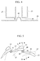
- FIG. 4 is a cross-sectional view showing a nozzle mount portion.
- a variable geometry turbocharger 3 includes the variable geometry radial turbine 1 and a compressor (not shown).
- variable geometry radial turbine 1 and the compressor are joined via a bearing housing 5.
- a turbine rotor 9 supported in a rotatable manner by a bearing 7 passes through the bearing housing 5.
- the compressor includes a compressor wheel (not shown) attached to one end of the turbine rotor 9, and a compressor casing (not shown) provided so as to enclose and cover the compressor wheel.
- variable geometry radial turbine 1 includes a turbine wheel 11 attached to the other end of the turbine rotor 9, a turbine casing 13 provided so as to enclose and cover the turbine wheel 11, and a variable nozzle mechanism 15 that varies the flow-path cross-sectional area (throat area) S for the exhaust gas (fluid) flowing into the turbine wheel 11.
- a scroll 19 is formed so as to surround the outer periphery of the turbine wheel 11, around a rotation axis 17 of the turbine rotor 9.
- This scroll 19 and a turbine wheel inlet 21 communicate with each other through a fluid inlet flow path (fluid space) 23.
- an exhaust gas inlet (not shown) extending generally in a tangential direction of the scroll 19 is provided on the outer circumferential side of the scroll 19, and an exhaust gas outlet 25 is provided along the rotation axis 17 of the turbine rotor 9.
- the variable nozzle mechanism 15 includes a plurality of nozzle vanes 27 having a blade shape in cross-section, as shown in FIG. 2 , a nozzle mount (opposing surface) 29 having a ring shape in cross-section, a drive ring 31 having a ring shape in cross-section, and a nozzle plate (opposing surface) 33 having a ring shape in cross-section.
- the nozzle mount 29 and the nozzle plate 33 are arranged to face each other, forming a donut-shaped fluid inlet flow path 23.
- the nozzle vanes 27 are arranged in the fluid inlet flow path 23 at equal intervals in the circumferential direction, and shafts 35 are provided on end surfaces of the nozzle vanes 27, on the nozzle mount 29 side.
- the shafts 35 are supported at the end surface of the nozzle mount 29 in a rotatable manner.
- Ends of the shafts 35 are fixed to ends of lever plates 37.
- the other ends of the lever plates 37 are engaged with drive pins 39 that are securely attached to the drive ring 31.
- the drive ring 31 is supported by the turbine casing 13 in a rotatable manner and is rotated by an actuator (illustration thereof is omitted).
- an actuator illustrated thereof is omitted.
- the drive ring 31 is rotated, the drive pins 39 move, and therefore, the lever plates 37 move.
- the lever plates 37 move, the shafts 35 rotate, and the nozzle vanes 27 turn on the shafts 35.
- the degree of opening of the nozzle vanes 27 is adjusted, in other words, the flow-path cross-sectional area S formed by adjacent nozzle vanes is adjusted.
- the nozzle plate 33 is provided with plate projections (projections) 41.
- the plate projections 41 are provided so as to cover the entire spaces between leading edges 40 of the nozzle vanes 27 and trailing edges 42 of the nozzle vanes 27 adjacent thereto when the nozzle vanes 27 are at a closed position.
- tips of the plate projections 41 are configured to protrude toward the nozzle vanes 27 further than the end surfaces of the nozzle vanes 27.
- the nozzle mount 29 is provided with mount projections (projections) 43.
- the mount projections 43 are provided so as to cover the entire spaces between the leading edges 40 of the nozzle vanes 27 and the trailing edges 42 of the nozzle vanes 27 adjacent thereto when the nozzle vanes 27 are at a closed position.
- tips of the mount projections 43 are configured to protrude toward the nozzle vanes 27 further than the end surfaces of the nozzle vanes 27.
- variable geometry radial turbine 1 The operation of the thus-configured variable geometry radial turbine 1 according to this embodiment and a variable geometry turbocharger having the same will now be described.
- Exhaust gas from an engine enters the scroll 19 and, while circulating along a spiral path of the scroll 19, flows into the fluid inlet flow path 23.
- the exhaust gas flowing into the fluid inlet flow path 23 is accelerated by the nozzle vanes 27 and flows into the turbine wheel 11 from the outer circumferential side thereof.
- This exhaust gas flows radially toward the center of the turbine wheel 11 and serves as expansion work acting on the turbine wheel 11, after which the exhaust gas flows axially to the outside by being guided by the exhaust gas outlet 25.
- the capacity of the variable geometry radial turbine is controlled in the following manner.
- the actuator (not shown) is activated to rotate the drive ring 31, the drive pins 39 are moved.
- the movement of the drive pins 39 causes the lever plates 37 to pivot about the shafts 35, making the shafts 35 rotate.
- the rotation of the shafts 35 causes the nozzle vanes 27 to turn on the shafts 35.
- the blade angle of the nozzle vanes 27 is changed, and the degree of opening of the nozzle vanes 27 is adjusted.
- the flow-path cross-sectional area S formed between the nozzle vanes 27 is adjusted, and the flow rate is adjusted.
- the plate projections 41 and the mount projections 43 are provided on the nozzle plate 33 and the nozzle mount 29, respectively, so as to cover the spaces between the leading edges 40 of the nozzle vanes 27 and the trailing edges 42 of the nozzle vanes 27 adjacent thereto when the nozzle vanes 27 are at a closed position.
- the plate projections 41 and the mount projections 43 exist next to the nozzle vanes 27.
- the plate projections 41 and mount projections 43 can cover the gap between the nozzle vanes 27 and the nozzle plate 33 and the gap between the nozzle vanes 27 and the nozzle mount 29. Accordingly, because the plate projections 41 and the mount projections 43 can suppress fluid leakage from these gaps, it is possible to suppress a decrease in efficiency of the variable geometry radial turbine 1 occurring when the flow rate is low.
- the plate projections 41 and the mount projections 43 are provided so as to cover the spaces between the leading edges 40 of the nozzle vanes 27 and the trailing edges 42 of the nozzle vanes 27 adjacent thereto when the nozzle vanes 27 are at a closed position, it is possible to reduce the height, H, of the flow-path cross-sectional area S, by the corresponding amount, when the nozzle vanes 27 are in a closed state.
- FIG. 3 shows a flow-path cross-sectional area, S1, having the same area as the flow-path cross-sectional area S according to this embodiment, but without the plate projections 41 or the mount projections 43. Comparison of the two shows that, because the flow-path cross-sectional area S has a smaller height H, the throat width B is larger than the throat width B1.
- the throat width B in other words, the degree of opening of the nozzle vanes 27, can be increased.
- the thickness of the trailing edges 42 of the nozzle vanes 27 relative to the throat width B can be relatively reduced. Because the rate of widening of the exhaust gas exiting the nozzle vanes 27 decreases as a result of this, it is possible to suppress the generation of a wake and to improve the performance of the variable geometry radial turbine 1.
- the plate projections 41 are provided on the nozzle plate 33, and the mount projections 43 are provided on the nozzle mount 29 in this embodiment, the configuration is not limited thereto; either one of the plate projections 41 and the mount projections 43 may be provided.
- variable geometry turbocharger having a variable geometry radial turbine 1 according to a second embodiment of the present invention will be described with reference to FIGS. 5 to 7 .
- this embodiment differs from the first embodiment in the configuration of the nozzle plate 33, the differences will be mainly described in this section, and overlapping descriptions of commonalities with the above-described first embodiment will be omitted.
- FIG. 5 is a plan view showing some of the nozzle vanes of the variable geometry radial turbine 1 according to this embodiment.
- FIG. 6 is a cross-sectional view taken along line B-B in FIG. 5 .
- FIG. 7 is a cross-sectional view taken along line C-C in FIG. 5 .
- the nozzle plate 33 has tapered outer-circumferential surfaces 51 formed on the outer circumferential side of the plate projections 41 and tapered toward the plate projections 41 so as to approach the nozzle vanes 27.
- the tapered outer-circumferential surfaces 51 are provided in areas in which the leading edges 40 of the nozzle vanes 27 move in response to opening or closing of the nozzle vanes 27.
- the tapered outer-circumferential surfaces 51 and the plate projections 41 are separated by a gap so that they do not touch each other.
- tapered surfaces equivalent to the tapered outer-circumferential surfaces 51 may be provided on the outer circumferential side of the mount projections 43.
- variable geometry radial turbine 1 According to this embodiment, Effects and advantages of the thus-configured variable geometry radial turbine 1 according to this embodiment will now be described.
- the tapered outer-circumferential surfaces 51 are in the areas in which the leading edges 40 of the nozzle vanes 27 move, if the degree of opening of the nozzle vanes 27 increases beyond a level at which it does not affect a decrease in efficiency, the distance between the nozzle vanes 27 and the nozzle plate 33 increases. Because an increase in the distance between the nozzle vanes 27 and the nozzle plate 33 allows more fluid to flow therebetween, the flow rate of the exhaust gas supplied from the nozzle vanes 27 to the turbine wheel 11 can be increased.
- the degree of opening of the nozzle vanes 27 decreases, the distance between the nozzle vanes 27 and the nozzle plate 33 decreases.
- the distance between the nozzle vanes 27 and the nozzle plate 33 can be changed in a continuous manner, by adjusting the inclination, areas, etc., of the tapered outer-circumferential surfaces 51, control of the flow rate of the exhaust gas can be easily performed.
- variable geometry turbocharger having a variable geometry radial turbine 1 according to a third embodiment of the present invention will be described with reference to FIGS. 8 to 10 .
- this embodiment differs from the first embodiment in the configuration of the nozzle plate 33, the differences will be mainly described in this section, and overlapping descriptions of commonalities with the above-described first embodiment will be omitted.
- FIG. 8 is a plan view showing some of the nozzle vanes of the variable geometry radial turbine 1 according to this embodiment.
- FIG. 9 is a cross-sectional view taken along line D-D in FIG. 8 .
- FIG. 10 is a cross-sectional view taken along line E-E in FIG. 8 .
- the nozzle plate 33 has tapered inner-circumferential surfaces 53 formed on the inner circumferential side of the plate projections 41 and tapered toward the plate projections 41 so as to approach the nozzle vanes 27.
- the tapered inner-circumferential surfaces 53 are provided in areas in which the trailing edges 42 of the nozzle vanes 27 move in response to opening or closing of the nozzle vanes 27.
- the tapered inner-circumferential surfaces 53 and the plate projections 41 are separated by a gap so that they do not touch each other.
- tapered surfaces equivalent to the tapered inner-circumferential surfaces 53 may be provided on the inner circumferential side of the mount projections 43.
- variable geometry radial turbine 1 According to this embodiment, Effects and advantages of the thus-configured variable geometry radial turbine 1 according to this embodiment will now be described.
- Exhaust gas between the nozzle plate 33 leaks out through the gap between the nozzle plate 33 and the nozzle vanes 27. Because portions of the tapered inner-circumferential surfaces 53 close to the plate projections 41 are located closer to the nozzle vanes 27, i.e., the tips of the plate projections 41, the exhaust gas smoothly moves from the plate projections 41 to the tapered inner-circumferential surfaces 53. Thus, because it is possible to suppress a sudden change in direction of the exhaust gas flow exiting the plate projections 41 through the gap, it is possible to suppress separation of the exhaust gas flow and to reduce the loss.
- the tapered inner-circumferential surfaces 53 are in the areas in which the trailing edges 42 of the nozzle vanes 27 move, if the degree of opening of the nozzle vanes 27 increases beyond a level at which it does not affect a decrease in efficiency, the distance between the nozzle vanes 27 and the nozzle plate 33 increases. Because an increase in the distance between the nozzle vanes 27 and the nozzle plate 33 allows more fluid to flow therebetween, the flow rate of the exhaust gas supplied from the nozzle vanes 27 to the turbine wheel 11 can be increased.
- the distance between the nozzle vanes 27 and the nozzle plate 33 can be changed in a continuous manner, by adjusting the inclination, areas, etc., of the tapered inner-circumferential surfaces 53, control of the flow rate of the exhaust gas can be easily performed.
- variable geometry turbocharger having a variable geometry radial turbine 1 according to a fourth embodiment of the present invention will be described with reference to FIGS. 11 to 13 .
- this embodiment differs from the first embodiment in the configuration of the nozzle plate 33, the differences will be mainly described in this section, and overlapping descriptions of commonalities with the above-described first embodiment will be omitted.
- FIG. 11 is a plan view showing some of the nozzle vanes of the variable geometry radial turbine 1 according to this embodiment.
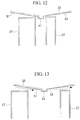
- FIG. 12 is a cross-sectional view taken along line F-F in FIG. 11 .
- FIG. 13 is a cross-sectional view taken along line G-G in FIG. 11 .
- the tapered outer-circumferential surfaces 51 of the second embodiment and the tapered inner-circumferential surfaces 53 of the third embodiment are provided.
- the tapered outer-circumferential surfaces 51 are provided in areas in which the leading edges 40 of the nozzle vanes 27 move in response to opening or closing of the nozzle vanes 27.
- the tapered inner-circumferential surfaces 53 are provided in areas in which the trailing edges 42 of the nozzle vanes 27 move in response to opening or closing of the nozzle vanes 27.
- tapered surfaces equivalent to the tapered outer-circumferential surfaces 51 may be provided on the outer circumferential side of the mount projections 43, and the tapered inner-circumferential surfaces 53 may be provided on the inner circumferential side of the mount projections 43.
- variable geometry radial turbine 1 effects and advantages of the thus-configured variable geometry radial turbine 1 according to this embodiment include those according to the above-described second embodiment and third embodiment. Thus, overlapping descriptions will be omitted in this section.
- variable geometry turbocharger having a variable geometry radial turbine 1 according to a fifth embodiment of the present invention will be described with reference to FIG. 14 .
- this embodiment differs from the fourth embodiment in the configuration of the nozzle plate 33, the differences will be mainly described in this section, and overlapping descriptions of commonalities with the above-described first embodiment will be omitted.
- the plate projections 41 are configured to cover areas from the leading edges 40 or trailing edges 42 of the nozzle vanes 27 to positions near the shafts 35, in a chord direction of the nozzle vanes 27.
- the lengths of the tapered outer-circumferential surfaces 51 and the tapered inner-circumferential surfaces 53 in the chord direction of the nozzle vanes 27 are set to be large.
- the mount projections 43 may cover areas from the leading edges 40 or trailing edges 42 of the nozzle vanes 27 to positions near the shafts 35, in the chord direction of the nozzle vanes 27.
- the plate projections 41 can cover substantially the entire areas in which the exhaust gas leaks from the gap between the nozzle vanes 27 and the nozzle plate 33 (indicated by dashed-line arrows in FIG. 14 ), in the chord direction of the nozzle vanes 27.
- tapered outer-circumferential surfaces 51 and the tapered inner-circumferential surfaces 53 may be omitted, or either the tapered outer-circumferential surfaces 51 or the tapered inner-circumferential surfaces 53 may be omitted.
- variable geometry radial turbine 1 in this embodiment, it may be applied to a mixed-flow turbine.
Landscapes
- Engineering & Computer Science (AREA)
- Mechanical Engineering (AREA)
- General Engineering & Computer Science (AREA)
- Chemical & Material Sciences (AREA)
- Chemical Kinetics & Catalysis (AREA)
- General Chemical & Material Sciences (AREA)
- Combustion & Propulsion (AREA)
- Supercharger (AREA)
- Control Of Turbines (AREA)
Claims (4)
- Turbine (1) mit variabler Geometrie, umfassend:einen Flüssigkeitsraum (23), der in Form eines Donuts durch ein Paar von ringartigen, einander gegenüberliegenden Flächen (29, 33) ausgebildet ist, die so angeordnet sind, dass sie in einem bestimmten Abstand voneinander einander zugewandt sind, und der ermöglicht, dass von einer äußeren Umfangsseite her fließendes Fluid in Richtung einer inneren Umfangsseite abgeführt werden kann; undeine Mehrzahl von Leitschaufeln (27), die in dem Flüssigkeitsraum (23) in bestimmten Abständen in einer Umfangsrichtung angeordnet sind, so dass sie den Flüssigkeitsraum aufteilen, wobei die Leitschaufeln durch Achsen (35) an einer der gegenüberliegenden Flächen so gelagert sind, dass sie sich drehen können;wobei die Leitschaufeln (27) zum Drehen auf den Achsen (35) gebracht werden, um durch benachbarte Leitschaufeln gebildete Engstellen zu öffnen oder zu schließen, so dass die Flussgeschwindigkeit des Fluids eingestellt werden kann,wobei mindestens eine des Paars von einander gegenüberliegenden Flächen (29, 33) mit Vorsprüngen (41, 43) versehen ist, die auf die Leitschaufeln zu weiter vorstehen als zumindest Endflächen der Leitschaufeln, um Zwischenräume zwischen Vorderkanten (40) der Leitschaufeln und Hinterkanten (42) von dazu benachbarten Leitschaufeln abzudecken, wenn die Leitschaufeln in einer geschlossenen Position sind, um die Höhe H der Querschnittsfläche S des Flussweges zu reduzieren; undwobei die Vorsprünge (41, 43) so ausgebildet sind, dass sie in der geschlossenen Position eine Querschnittsfläche (S) des Flussweges mit einer in Bezug auf den besagten Abstand reduzierten Höhe (H) in einer Richtung entlang der Achse definieren.
- Turbine mit variabler Geometrie nach Anspruch 1, wobei sich verjüngende äußere Umfangsflächen, die sich auf die Vorsprünge zu verjüngen, um sich den Leitschaufeln (27) anzunähern, an der äußeren Umfangsseite der Vorsprünge (41, 43) vorgesehen sind.
- Turbine mit variabler Geometrie nach Anspruch 1 oder 2, wobei sich verjüngende innere Umfangsflächen, die sich auf die Vorsprünge (41, 43) zu verjüngen, um sich den Leitschaufeln (27) anzunähern, an der inneren Umfangsseite der Vorsprünge (41, 43) vorgesehen sind.
- Turbine mit variabler Geometrie nach einem der Ansprüche 1 bis 3, wobei die Vorsprünge (41, 43) Abschnitte von den Vorderkanten oder den Hinterkanten der Leitschaufeln (27) zu Positionen nahe den Achsen (35) in einer Richtung der Sehne der Leitschaufeln (27) abdecken.
Applications Claiming Priority (2)
| Application Number | Priority Date | Filing Date | Title |
|---|---|---|---|
| JP2010222496A JP5524010B2 (ja) | 2010-09-30 | 2010-09-30 | 可変容量タービン |
| PCT/JP2011/069817 WO2012043125A1 (ja) | 2010-09-30 | 2011-08-31 | 可変容量タービン |
Publications (3)
| Publication Number | Publication Date |
|---|---|
| EP2623728A1 EP2623728A1 (de) | 2013-08-07 |
| EP2623728A4 EP2623728A4 (de) | 2014-03-12 |
| EP2623728B1 true EP2623728B1 (de) | 2016-01-20 |
Family
ID=45892599
Family Applications (1)
| Application Number | Title | Priority Date | Filing Date |
|---|---|---|---|
| EP11828686.3A Active EP2623728B1 (de) | 2010-09-30 | 2011-08-31 | Turbine mit variabler geometrie |
Country Status (5)
| Country | Link |
|---|---|
| US (1) | US9028202B2 (de) |
| EP (1) | EP2623728B1 (de) |
| JP (1) | JP5524010B2 (de) |
| CN (1) | CN103026005B (de) |
| WO (1) | WO2012043125A1 (de) |
Families Citing this family (10)
| Publication number | Priority date | Publication date | Assignee | Title |
|---|---|---|---|---|
| KR100735627B1 (ko) * | 2004-12-30 | 2007-07-04 | 매그나칩 반도체 유한회사 | 반도체 소자의 게이트 구조 및 그 형성 방법 |
| CN103206266A (zh) * | 2013-04-15 | 2013-07-17 | 无锡科博增压器有限公司 | 一种用于涡轮增压器的高效导向环 |
| CN103883365B (zh) * | 2014-03-25 | 2016-08-24 | 杜身晓 | 一种重型卡车的可变截面涡轮增压器 |
| DE112017001114B4 (de) * | 2016-03-03 | 2022-10-27 | Ihi Corporation | Düsenantriebsmechanismus, Turbolader und Turbolader mit variabler Kapazität |
| US10393009B2 (en) * | 2016-04-19 | 2019-08-27 | Garrett Transportation I Inc. | Adjustable-trim centrifugal compressor for a turbocharger |
| KR101764059B1 (ko) | 2016-07-04 | 2017-08-01 | 두산중공업 주식회사 | 가스 터빈 엔진용 프리 스월러 |
| JP7008789B2 (ja) | 2018-02-28 | 2022-01-25 | 三菱重工エンジン&ターボチャージャ株式会社 | 半径流入式タービン及びターボチャージャー |
| US11965431B2 (en) | 2020-01-07 | 2024-04-23 | Mitsubishi Heavy Industries Engine & Turbocharger, Ltd | Turbine and turbocharger |
| US11359506B2 (en) * | 2020-01-13 | 2022-06-14 | Raytheon Technologies Corporation | Contoured stop for variable area turbine |
| WO2023162115A1 (ja) * | 2022-02-25 | 2023-08-31 | 三菱重工エンジン&ターボチャージャ株式会社 | 可変ノズル装置及び可変容量型ターボチャージャ |
Family Cites Families (12)
| Publication number | Priority date | Publication date | Assignee | Title |
|---|---|---|---|---|
| JPH0759881B2 (ja) | 1988-04-15 | 1995-06-28 | 本田技研工業株式会社 | 可変容量タービン |
| DE3941715A1 (de) | 1989-12-18 | 1991-06-20 | Porsche Ag | Abgasturbolader fuer eine brennkraftmaschine |
| JP2000008869A (ja) | 1998-06-18 | 2000-01-11 | Hitachi Ltd | 可変容量ターボ過給機 |
| JP2002364374A (ja) | 2001-06-08 | 2002-12-18 | Hitachi Ltd | 可変容量ターボ過給機 |
| AU2003223210A1 (en) * | 2002-03-01 | 2003-09-16 | Honeywell International Inc. | Improved vane design for use in variable geometry_turbocharger |
| DE10329281A1 (de) * | 2003-06-30 | 2005-01-20 | Daimlerchrysler Ag | Verdichter im Ansaugtrakt einer Brennkraftmaschine |
| JP4807271B2 (ja) * | 2007-01-30 | 2011-11-02 | 株式会社Ihi | 可変容量型過給機 |
| JP5082991B2 (ja) | 2008-03-31 | 2012-11-28 | 株式会社Ihi | 過給機 |
| US8056336B2 (en) | 2008-05-05 | 2011-11-15 | Honeywell International Inc. | Turbocharger with variable nozzle having vane sealing surfaces |
| JP2010096018A (ja) * | 2008-10-14 | 2010-04-30 | Ihi Corp | タービンとこれを備える過給機 |
| JP2010127093A (ja) | 2008-11-25 | 2010-06-10 | Ihi Corp | ターボチャージャ |
| JP2010180811A (ja) | 2009-02-06 | 2010-08-19 | Ihi Corp | 可変容量型タービン |
-
2010
- 2010-09-30 JP JP2010222496A patent/JP5524010B2/ja active Active
-
2011
- 2011-08-31 US US13/807,258 patent/US9028202B2/en active Active
- 2011-08-31 EP EP11828686.3A patent/EP2623728B1/de active Active
- 2011-08-31 CN CN201180032575.6A patent/CN103026005B/zh active Active
- 2011-08-31 WO PCT/JP2011/069817 patent/WO2012043125A1/ja active Application Filing
Also Published As
| Publication number | Publication date |
|---|---|
| CN103026005A (zh) | 2013-04-03 |
| JP5524010B2 (ja) | 2014-06-18 |
| US20130294895A1 (en) | 2013-11-07 |
| EP2623728A1 (de) | 2013-08-07 |
| CN103026005B (zh) | 2016-05-11 |
| JP2012077661A (ja) | 2012-04-19 |
| EP2623728A4 (de) | 2014-03-12 |
| WO2012043125A1 (ja) | 2012-04-05 |
| US9028202B2 (en) | 2015-05-12 |
Similar Documents
| Publication | Publication Date | Title |
|---|---|---|
| EP2623728B1 (de) | Turbine mit variabler geometrie | |
| EP2787181B1 (de) | Radialturbine | |
| US8123471B2 (en) | Variable stator vane contoured button | |
| EP2096264B1 (de) | Turbine mit variabler Geometrie und Turbolader | |
| US9039357B2 (en) | Seal assembly including grooves in a radially outwardly facing side of a platform in a gas turbine engine | |
| WO2015002142A1 (ja) | 可変ノズルユニット及び可変容量型過給機 | |
| EP3173584B1 (de) | Ein-/aus-ventilvorrichtung und drehmaschine | |
| CN106121737A (zh) | 带有一体式旁通机构的可变叶片涡轮机喷嘴的涡轮增压器 | |
| JP5201333B2 (ja) | 可変ノズルのベーン形状及び可変容量過給機 | |
| JP5281724B1 (ja) | 過給機用軸流タービン | |
| US11047256B2 (en) | Variable nozzle unit and turbocharger | |
| JP2015031237A (ja) | 可変ノズルユニット及び可変容量型過給機 | |
| EP3705698B1 (de) | Turbine und turbolader | |
| WO2017072843A1 (ja) | 回転機械 | |
| EP3421754B1 (de) | Turbolader mit variabler geometrie | |
| JP2007192180A (ja) | ターボチャージャのタービン | |
| CN111287801B (zh) | 蒸汽轮机 | |
| CN115135854A (zh) | 具有配备有用于校正气流回转的翅片的内部次级空间的涡轮 | |
| JP2011231779A (ja) | タービンおよびこれを備えるターボチャージャ | |
| EP3705697B1 (de) | Turbine und turbolader | |
| JP2020165374A (ja) | タービンおよび過給機 | |
| JP7248113B2 (ja) | 過給機 | |
| JP7302738B2 (ja) | 可変容量型過給機 | |
| WO2023139639A1 (ja) | 可変容量タービン及びこれを備えるターボチャージャー | |
| JP2011231780A (ja) | タービンおよびこれを備えるターボチャージャ |
Legal Events
| Date | Code | Title | Description |
|---|---|---|---|
| PUAI | Public reference made under article 153(3) epc to a published international application that has entered the european phase |
Free format text: ORIGINAL CODE: 0009012 |
|
| 17P | Request for examination filed |
Effective date: 20121228 |
|
| AK | Designated contracting states |
Kind code of ref document: A1 Designated state(s): AL AT BE BG CH CY CZ DE DK EE ES FI FR GB GR HR HU IE IS IT LI LT LU LV MC MK MT NL NO PL PT RO RS SE SI SK SM TR |
|
| DAX | Request for extension of the european patent (deleted) | ||
| A4 | Supplementary search report drawn up and despatched |
Effective date: 20140210 |
|
| RIC1 | Information provided on ipc code assigned before grant |
Ipc: F01D 17/26 20060101ALI20140204BHEP Ipc: F02B 37/24 20060101ALI20140204BHEP Ipc: F01D 17/16 20060101AFI20140204BHEP |
|
| 17Q | First examination report despatched |
Effective date: 20140911 |
|
| GRAP | Despatch of communication of intention to grant a patent |
Free format text: ORIGINAL CODE: EPIDOSNIGR1 |
|
| INTG | Intention to grant announced |
Effective date: 20150722 |
|
| GRAS | Grant fee paid |
Free format text: ORIGINAL CODE: EPIDOSNIGR3 |
|
| GRAA | (expected) grant |
Free format text: ORIGINAL CODE: 0009210 |
|
| AK | Designated contracting states |
Kind code of ref document: B1 Designated state(s): AL AT BE BG CH CY CZ DE DK EE ES FI FR GB GR HR HU IE IS IT LI LT LU LV MC MK MT NL NO PL PT RO RS SE SI SK SM TR |
|
| REG | Reference to a national code |
Ref country code: GB Ref legal event code: FG4D |
|
| REG | Reference to a national code |
Ref country code: CH Ref legal event code: EP |
|
| REG | Reference to a national code |
Ref country code: IE Ref legal event code: FG4D |
|
| REG | Reference to a national code |
Ref country code: AT Ref legal event code: REF Ref document number: 771827 Country of ref document: AT Kind code of ref document: T Effective date: 20160215 |
|
| REG | Reference to a national code |
Ref country code: DE Ref legal event code: R096 Ref document number: 602011022895 Country of ref document: DE |
|
| REG | Reference to a national code |
Ref country code: NL Ref legal event code: FP |
|
| REG | Reference to a national code |
Ref country code: LT Ref legal event code: MG4D |
|
| REG | Reference to a national code |
Ref country code: AT Ref legal event code: MK05 Ref document number: 771827 Country of ref document: AT Kind code of ref document: T Effective date: 20160120 |
|
| REG | Reference to a national code |
Ref country code: FR Ref legal event code: PLFP Year of fee payment: 6 |
|
| PG25 | Lapsed in a contracting state [announced via postgrant information from national office to epo] |
Ref country code: GR Free format text: LAPSE BECAUSE OF FAILURE TO SUBMIT A TRANSLATION OF THE DESCRIPTION OR TO PAY THE FEE WITHIN THE PRESCRIBED TIME-LIMIT Effective date: 20160421 Ref country code: NO Free format text: LAPSE BECAUSE OF FAILURE TO SUBMIT A TRANSLATION OF THE DESCRIPTION OR TO PAY THE FEE WITHIN THE PRESCRIBED TIME-LIMIT Effective date: 20160420 Ref country code: IT Free format text: LAPSE BECAUSE OF FAILURE TO SUBMIT A TRANSLATION OF THE DESCRIPTION OR TO PAY THE FEE WITHIN THE PRESCRIBED TIME-LIMIT Effective date: 20160120 Ref country code: ES Free format text: LAPSE BECAUSE OF FAILURE TO SUBMIT A TRANSLATION OF THE DESCRIPTION OR TO PAY THE FEE WITHIN THE PRESCRIBED TIME-LIMIT Effective date: 20160120 Ref country code: FI Free format text: LAPSE BECAUSE OF FAILURE TO SUBMIT A TRANSLATION OF THE DESCRIPTION OR TO PAY THE FEE WITHIN THE PRESCRIBED TIME-LIMIT Effective date: 20160120 Ref country code: HR Free format text: LAPSE BECAUSE OF FAILURE TO SUBMIT A TRANSLATION OF THE DESCRIPTION OR TO PAY THE FEE WITHIN THE PRESCRIBED TIME-LIMIT Effective date: 20160120 |
|
| PG25 | Lapsed in a contracting state [announced via postgrant information from national office to epo] |
Ref country code: LV Free format text: LAPSE BECAUSE OF FAILURE TO SUBMIT A TRANSLATION OF THE DESCRIPTION OR TO PAY THE FEE WITHIN THE PRESCRIBED TIME-LIMIT Effective date: 20160120 Ref country code: SE Free format text: LAPSE BECAUSE OF FAILURE TO SUBMIT A TRANSLATION OF THE DESCRIPTION OR TO PAY THE FEE WITHIN THE PRESCRIBED TIME-LIMIT Effective date: 20160120 Ref country code: LT Free format text: LAPSE BECAUSE OF FAILURE TO SUBMIT A TRANSLATION OF THE DESCRIPTION OR TO PAY THE FEE WITHIN THE PRESCRIBED TIME-LIMIT Effective date: 20160120 Ref country code: AT Free format text: LAPSE BECAUSE OF FAILURE TO SUBMIT A TRANSLATION OF THE DESCRIPTION OR TO PAY THE FEE WITHIN THE PRESCRIBED TIME-LIMIT Effective date: 20160120 Ref country code: PL Free format text: LAPSE BECAUSE OF FAILURE TO SUBMIT A TRANSLATION OF THE DESCRIPTION OR TO PAY THE FEE WITHIN THE PRESCRIBED TIME-LIMIT Effective date: 20160120 Ref country code: PT Free format text: LAPSE BECAUSE OF FAILURE TO SUBMIT A TRANSLATION OF THE DESCRIPTION OR TO PAY THE FEE WITHIN THE PRESCRIBED TIME-LIMIT Effective date: 20160520 Ref country code: IS Free format text: LAPSE BECAUSE OF FAILURE TO SUBMIT A TRANSLATION OF THE DESCRIPTION OR TO PAY THE FEE WITHIN THE PRESCRIBED TIME-LIMIT Effective date: 20160520 Ref country code: RS Free format text: LAPSE BECAUSE OF FAILURE TO SUBMIT A TRANSLATION OF THE DESCRIPTION OR TO PAY THE FEE WITHIN THE PRESCRIBED TIME-LIMIT Effective date: 20160120 |
|
| REG | Reference to a national code |
Ref country code: DE Ref legal event code: R097 Ref document number: 602011022895 Country of ref document: DE |
|
| PG25 | Lapsed in a contracting state [announced via postgrant information from national office to epo] |
Ref country code: EE Free format text: LAPSE BECAUSE OF FAILURE TO SUBMIT A TRANSLATION OF THE DESCRIPTION OR TO PAY THE FEE WITHIN THE PRESCRIBED TIME-LIMIT Effective date: 20160120 Ref country code: DK Free format text: LAPSE BECAUSE OF FAILURE TO SUBMIT A TRANSLATION OF THE DESCRIPTION OR TO PAY THE FEE WITHIN THE PRESCRIBED TIME-LIMIT Effective date: 20160120 |
|
| PLBE | No opposition filed within time limit |
Free format text: ORIGINAL CODE: 0009261 |
|
| STAA | Information on the status of an ep patent application or granted ep patent |
Free format text: STATUS: NO OPPOSITION FILED WITHIN TIME LIMIT |
|
| PG25 | Lapsed in a contracting state [announced via postgrant information from national office to epo] |
Ref country code: CZ Free format text: LAPSE BECAUSE OF FAILURE TO SUBMIT A TRANSLATION OF THE DESCRIPTION OR TO PAY THE FEE WITHIN THE PRESCRIBED TIME-LIMIT Effective date: 20160120 Ref country code: SM Free format text: LAPSE BECAUSE OF FAILURE TO SUBMIT A TRANSLATION OF THE DESCRIPTION OR TO PAY THE FEE WITHIN THE PRESCRIBED TIME-LIMIT Effective date: 20160120 Ref country code: RO Free format text: LAPSE BECAUSE OF FAILURE TO SUBMIT A TRANSLATION OF THE DESCRIPTION OR TO PAY THE FEE WITHIN THE PRESCRIBED TIME-LIMIT Effective date: 20160120 Ref country code: SK Free format text: LAPSE BECAUSE OF FAILURE TO SUBMIT A TRANSLATION OF THE DESCRIPTION OR TO PAY THE FEE WITHIN THE PRESCRIBED TIME-LIMIT Effective date: 20160120 |
|
| 26N | No opposition filed |
Effective date: 20161021 |
|
| PG25 | Lapsed in a contracting state [announced via postgrant information from national office to epo] |
Ref country code: BE Free format text: LAPSE BECAUSE OF FAILURE TO SUBMIT A TRANSLATION OF THE DESCRIPTION OR TO PAY THE FEE WITHIN THE PRESCRIBED TIME-LIMIT Effective date: 20160120 |
|
| PG25 | Lapsed in a contracting state [announced via postgrant information from national office to epo] |
Ref country code: SI Free format text: LAPSE BECAUSE OF FAILURE TO SUBMIT A TRANSLATION OF THE DESCRIPTION OR TO PAY THE FEE WITHIN THE PRESCRIBED TIME-LIMIT Effective date: 20160120 Ref country code: BG Free format text: LAPSE BECAUSE OF FAILURE TO SUBMIT A TRANSLATION OF THE DESCRIPTION OR TO PAY THE FEE WITHIN THE PRESCRIBED TIME-LIMIT Effective date: 20160420 |
|
| PG25 | Lapsed in a contracting state [announced via postgrant information from national office to epo] |
Ref country code: MC Free format text: LAPSE BECAUSE OF FAILURE TO SUBMIT A TRANSLATION OF THE DESCRIPTION OR TO PAY THE FEE WITHIN THE PRESCRIBED TIME-LIMIT Effective date: 20160120 |
|
| REG | Reference to a national code |
Ref country code: CH Ref legal event code: PL |
|
| PG25 | Lapsed in a contracting state [announced via postgrant information from national office to epo] |
Ref country code: CH Free format text: LAPSE BECAUSE OF NON-PAYMENT OF DUE FEES Effective date: 20160831 Ref country code: LI Free format text: LAPSE BECAUSE OF NON-PAYMENT OF DUE FEES Effective date: 20160831 |
|
| REG | Reference to a national code |
Ref country code: IE Ref legal event code: MM4A |
|
| REG | Reference to a national code |
Ref country code: FR Ref legal event code: PLFP Year of fee payment: 7 |
|
| PG25 | Lapsed in a contracting state [announced via postgrant information from national office to epo] |
Ref country code: IE Free format text: LAPSE BECAUSE OF NON-PAYMENT OF DUE FEES Effective date: 20160831 |
|
| PG25 | Lapsed in a contracting state [announced via postgrant information from national office to epo] |
Ref country code: LU Free format text: LAPSE BECAUSE OF NON-PAYMENT OF DUE FEES Effective date: 20160831 |
|
| PG25 | Lapsed in a contracting state [announced via postgrant information from national office to epo] |
Ref country code: HU Free format text: LAPSE BECAUSE OF FAILURE TO SUBMIT A TRANSLATION OF THE DESCRIPTION OR TO PAY THE FEE WITHIN THE PRESCRIBED TIME-LIMIT; INVALID AB INITIO Effective date: 20110831 Ref country code: CY Free format text: LAPSE BECAUSE OF FAILURE TO SUBMIT A TRANSLATION OF THE DESCRIPTION OR TO PAY THE FEE WITHIN THE PRESCRIBED TIME-LIMIT Effective date: 20160120 |
|
| PG25 | Lapsed in a contracting state [announced via postgrant information from national office to epo] |
Ref country code: MT Free format text: LAPSE BECAUSE OF NON-PAYMENT OF DUE FEES Effective date: 20160831 Ref country code: MK Free format text: LAPSE BECAUSE OF FAILURE TO SUBMIT A TRANSLATION OF THE DESCRIPTION OR TO PAY THE FEE WITHIN THE PRESCRIBED TIME-LIMIT Effective date: 20160120 Ref country code: TR Free format text: LAPSE BECAUSE OF FAILURE TO SUBMIT A TRANSLATION OF THE DESCRIPTION OR TO PAY THE FEE WITHIN THE PRESCRIBED TIME-LIMIT Effective date: 20160120 |
|
| REG | Reference to a national code |
Ref country code: FR Ref legal event code: PLFP Year of fee payment: 8 |
|
| PG25 | Lapsed in a contracting state [announced via postgrant information from national office to epo] |
Ref country code: AL Free format text: LAPSE BECAUSE OF FAILURE TO SUBMIT A TRANSLATION OF THE DESCRIPTION OR TO PAY THE FEE WITHIN THE PRESCRIBED TIME-LIMIT Effective date: 20160120 |
|
| PGFP | Annual fee paid to national office [announced via postgrant information from national office to epo] |
Ref country code: NL Payment date: 20220715 Year of fee payment: 12 |
|
| PGFP | Annual fee paid to national office [announced via postgrant information from national office to epo] |
Ref country code: GB Payment date: 20220707 Year of fee payment: 12 |
|
| PGFP | Annual fee paid to national office [announced via postgrant information from national office to epo] |
Ref country code: FR Payment date: 20220709 Year of fee payment: 12 |
|
| PGFP | Annual fee paid to national office [announced via postgrant information from national office to epo] |
Ref country code: DE Payment date: 20230705 Year of fee payment: 13 |
|
| REG | Reference to a national code |
Ref country code: NL Ref legal event code: MM Effective date: 20230901 |
|
| GBPC | Gb: european patent ceased through non-payment of renewal fee |
Effective date: 20230831 |
|
| PG25 | Lapsed in a contracting state [announced via postgrant information from national office to epo] |
Ref country code: NL Free format text: LAPSE BECAUSE OF NON-PAYMENT OF DUE FEES Effective date: 20230901 |