EP2617961B1 - Radial turbine - Google Patents
Radial turbine Download PDFInfo
- Publication number
- EP2617961B1 EP2617961B1 EP11853195.3A EP11853195A EP2617961B1 EP 2617961 B1 EP2617961 B1 EP 2617961B1 EP 11853195 A EP11853195 A EP 11853195A EP 2617961 B1 EP2617961 B1 EP 2617961B1
- Authority
- EP
- European Patent Office
- Prior art keywords
- tongue portion
- turbine
- flow passage
- exhaust gas
- offset
- Prior art date
- Legal status (The legal status is an assumption and is not a legal conclusion. Google has not performed a legal analysis and makes no representation as to the accuracy of the status listed.)
- Not-in-force
Links
Images


Classifications
-
- F—MECHANICAL ENGINEERING; LIGHTING; HEATING; WEAPONS; BLASTING
- F04—POSITIVE - DISPLACEMENT MACHINES FOR LIQUIDS; PUMPS FOR LIQUIDS OR ELASTIC FLUIDS
- F04D—NON-POSITIVE-DISPLACEMENT PUMPS
- F04D29/00—Details, component parts, or accessories
- F04D29/40—Casings; Connections of working fluid
- F04D29/42—Casings; Connections of working fluid for radial or helico-centrifugal pumps
-
- F—MECHANICAL ENGINEERING; LIGHTING; HEATING; WEAPONS; BLASTING
- F01—MACHINES OR ENGINES IN GENERAL; ENGINE PLANTS IN GENERAL; STEAM ENGINES
- F01D—NON-POSITIVE DISPLACEMENT MACHINES OR ENGINES, e.g. STEAM TURBINES
- F01D9/00—Stators
- F01D9/02—Nozzles; Nozzle boxes; Stator blades; Guide conduits, e.g. individual nozzles
- F01D9/026—Scrolls for radial machines or engines
-
- F—MECHANICAL ENGINEERING; LIGHTING; HEATING; WEAPONS; BLASTING
- F02—COMBUSTION ENGINES; HOT-GAS OR COMBUSTION-PRODUCT ENGINE PLANTS
- F02C—GAS-TURBINE PLANTS; AIR INTAKES FOR JET-PROPULSION PLANTS; CONTROLLING FUEL SUPPLY IN AIR-BREATHING JET-PROPULSION PLANTS
- F02C6/00—Plural gas-turbine plants; Combinations of gas-turbine plants with other apparatus; Adaptations of gas-turbine plants for special use
- F02C6/04—Gas-turbine plants providing heated or pressurised working fluid for other apparatus, e.g. without mechanical power output
- F02C6/10—Gas-turbine plants providing heated or pressurised working fluid for other apparatus, e.g. without mechanical power output supplying working fluid to a user, e.g. a chemical process, which returns working fluid to a turbine of the plant
- F02C6/12—Turbochargers, i.e. plants for augmenting mechanical power output of internal-combustion piston engines by increase of charge pressure
-
- F—MECHANICAL ENGINEERING; LIGHTING; HEATING; WEAPONS; BLASTING
- F05—INDEXING SCHEMES RELATING TO ENGINES OR PUMPS IN VARIOUS SUBCLASSES OF CLASSES F01-F04
- F05D—INDEXING SCHEME FOR ASPECTS RELATING TO NON-POSITIVE-DISPLACEMENT MACHINES OR ENGINES, GAS-TURBINES OR JET-PROPULSION PLANTS
- F05D2220/00—Application
- F05D2220/40—Application in turbochargers
Definitions
- the present invention relates to a scroll part structure that forms an exhaust gas passage of a radial turbine, which is used in a turbocharger (exhaust gas turbocharger) of an internal combustion engine, and configured to rotate a turbine rotor by introducing exhaust gas from the spiral scroll part radially toward blades of the turbine rotor to exert a force on the blades, then discharging the gas in an axial direction.
- a turbocharger exhaust gas turbocharger
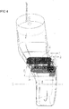
- FIG. 6 shows an example of a conventional turbocharger that uses such a radial turbine disclosed in Japanese Patent Application Laid-open No. 2003-120303 (Patent Document 1).
- reference numeral 01 denotes a turbine housing
- 04 denotes a spiral scroll part formed inside the turbine housing 01
- 05 denotes an exhaust gas discharge passage formed by the inner circumference of the turbine housing 01
- 06 denotes a compressor housing
- 09 denotes a bearing housing that connects the turbine housing 01 and the compressor housing 06.
- Reference numeral 010 denotes a turbine wheel that has a plurality of circumferentially equally spaced turbine blades 03 fixed around the rim.
- Reference numeral 07 denotes a compressor impeller
- 08 denotes a diffuser provided at the air outlet of the compressor impeller 07
- 012 denotes a rotor shaft that connects the turbine wheel 010 and the compressor impeller 07.
- Reference numeral 011 denotes a pair of bearings attached to the bearing housing 09 to support the rotor shaft 012.
- Reference symbol L1 denotes the rotation axis of the turbine wheel 010, the compressor impeller, and the rotor shaft 012.
- exhaust gas from an internal combustion engine enters the scroll part 04, and while traveling around along the spiral shape of the scroll part 04, it flows to the turbine blades 03 from the outer circumferential inlet ends thereof, then radially flows toward the center of the turbine wheel 010. Having done the expansion work on the turbine wheel 010, the gas then flows in the direction of axis line L1 of the rotor shaft 012 and is discharged from the exhaust gas discharge passage 05 to the outside of the turbocharger.
- FIG. 7A shows a schematic configuration diagram of a cross section, in a direction perpendicular to the axis line L1 of the rotor shaft 012, of a tongue portion and its vicinity formed inside at the exhaust gas inlet of the radial turbine of Patent Document 1.
- FIG. 7B is a diagram viewed from a direction of arrow W in FIG. 7A .
- 04 denotes the scroll part
- 044 denotes the exhaust gas inlet
- 045 denotes a tongue portion, which is formed at a connecting part between a flow passage 046, which the exhaust gas from the exhaust gas inlet 044 passes through to be introduced into the scroll part 04, and a blade side passage 047, into which the gas flows toward the blades, the tongue portion 045 separating the two passages 046 and 047.
- the tongue portion 045 is subjected to the heat of exhaust gas both from the flow passage 046 and the blade side passage 047 as shown in FIG. 7B . Moreover, the tongue portion 045 has poor heat dissipation efficiency to dissipate the accumulated heat because of the narrow heat dissipation path as indicated by the arrow Z.
- the temperature of the tongue portion 045 can sometimes reach 800 to 900°C.
- Patent Document 1 Japanese Patent Application Laid-open No. 2003-120303
- the high-temperature exhaust gas from the engine passes through the flow passage 046, and while traveling around along the spiral shape of the scroll part 04, it flows out into the blade side passage 047.
- the tongue portion 045 As the tongue portion 045 is exposed to the high-temperature exhaust gas from both of the flow passage 046 and the blade side passage 047, and because of its heat dissipation path being only in the direction Z (see FIG. 7A ), heat tends to accumulate. The tongue portion 045 is therefore prone to surface oxidation due to the high temperature, or to fatigue damage resulting from thermal stress.
- a countermeasure for this problem is to use a material having good oxidation resistance and fatigue resistance at high temperatures (such as cast austenitic stainless steel or cast ferritic stainless steel) for the turbine housing 01, which is expensive and causing an increase in cost.
- turbocharger has an EGR pipe through which part of exhaust gas is extracted from an exhaust manifold, internally divided by a partition for preventing exhaust interference between cylinders, to be recirculated to a suction pipe.
- French patent FR 2 801 072 discloses a turbocharger for a motor vehicle internal combustion engine having the exhaust duct from the engine fed to a pair of feed pipes into the turbocharger chamber.
- US patent US 4 530 640 discloses a turbocharged engine having a turbine housing which has an inlet, an outlet located radially interiorally from the inlet, a centrally located turbine wheel cavity, and an internal scroll passageway which diminishes in cross section as it leads from the inlet around the turbine wheel cavity.
- FIG. 2010/229551 Another example of a turbocharger is also disclosed in US patent US 2010/229551 , which provides a turbine housing for a turbocharger for use in a reciprocating internal combustion engine including a housing which has a housing axis and configured to house a rotatable shaft having a turbine wheel disposed thereon.
- the present invention is directed to a radial turbine as defined in claim 1 and was made to solve this problem.
- An object of the invention is to enable a cost reduction through downgrading of heat resistance of the material used for the connecting part (tongue portion) of the turbine housing, by enlarging the surface area of exposure to the external air of the outer part of the connecting part to increase the amount of heat dissipation therefrom and to reduce accumulation of heat in the tongue portion.
- the present invention provides a turbine scroll part structure of a radial turbine configured to rotate a turbine rotor by introducing exhaust gas from a spiral scroll part formed inside a turbine housing radially toward blades of the scroll part to exert a force on the blades, then discharging the gas in an axial direction, wherein a flow passage of a connecting part between an exhaust gas inlet into the turbine housing and the scroll part is offset along an axis line of a rotating shaft of the turbine rotor, whereby a wall surface exposed to external air is formed in a vicinity of a tongue portion that separates the flow passage from a blade side passage through which the exhaust gas flows toward the blades, so that heat in the vicinity of the tongue portion is dissipated from the wall surface.
- the outer part of the connecting part of the turbine housing has a greater surface area that is exposed and heat dissipation therefrom is increased, and accumulation of heat in the tongue portion is reduced, whereby a cost reduction is made possible through downgrading of heat resistance of the material used for the connecting part.
- forming a cut-out portion can provide an effect of reducing the amount of heat applied to the tongue portion.
- the wall surface may have an axial length changing in accordance with an amount of the offsetting, and the offset amount of the flow passage may be gradually increased from a distal end of the tongue portion.
- the flow passage may be offset by deforming only an inner circumferential side of the spiral shape.
- the flow passage may be offset around the axis center in an amount gradually increasing from a distal end of the tongue portion where the offset amount is zero, to an angular position at an angle of substantially 45° toward an exhaust gas inlet side.
- the offset amount is reduced from the angular position at substantially 45° around the axis center toward the exhaust gas inlet side such that the offset amount is zero at the distal end of the tongue portion, so that the exhaust gas flow is guided in a predetermined direction, which will result in less flow loss of exhaust gas.
- the outer part of the connecting part has a greater surface area that is exposed and heat dissipation therefrom is increased, and accumulation of heat in the tongue portion is reduced, whereby a cost reduction is made possible through downgrading of heat resistance of the material used for the connecting part.
- FIG. 1 shows a schematic configuration diagram of the exhaust gas passage space in a scroll part according to a first embodiment of the present invention.
- reference numeral 01 denotes a turbine housing
- 04 denotes a spiral scroll part formed inside the turbine housing 01
- 05 denotes an exhaust gas discharge passage formed by the inner circumference of the turbine housing 01
- 06 denotes a compressor housing
- 09 denotes a bearing housing that connects the turbine housing 01 and the compressor housing 06.
- Reference numeral 010 denotes a turbine wheel that has a plurality of circumferentially equally spaced turbine blades 03 fixed around the rim.
- Reference numeral 07 denotes a compressor impeller, 08 a diffuser provided at the air outlet of the compressor impeller 07, and 012 a rotor shaft that connects the turbine wheel 010 and the compressor impeller 07.
- Reference numeral 011 denotes a pair of bearings attached to the bearing housing 09 to support the rotor shaft 12.
- Reference symbol L1 denotes the rotation axis of the turbine wheel 010, the compressor impeller, and the rotor shaft 012.
- exhaust gas from an internal combustion engine enters the scroll 04 through an exhaust gas inlet, and while traveling around along the spiral of the scroll part 04, it flows to the plurality of turbine blades 03 from the outer circumferential inlet ends thereof, then radially flows toward the center of the turbine wheel 010. Having done the expansion work on the turbine wheel 010, the gas then flows axially and exits from the exhaust gas discharge passage 05.
- the basic structure of the turbocharger with a radial turbine is similar to that of the conventional counterparts as illustrated above.
- the present invention offers an improvement in the scroll shape.
- FIG. 1A is a cross-sectional view, in a direction perpendicular to the turbine rotor axis line, of a tongue portion according to the first embodiment of the present invention
- FIG. 1B is a schematic configuration diagram of essential parts as viewed from the direction of arrow G in FIG. 1A , illustrating a cross section of the scroll part and an upper half along the rotation axis line of the turbine rotor.
- Reference numeral 3 denotes a flow passage formed by the turbine housing 5 for letting the exhaust gas flow into the scroll part 1 from the exhaust gas inlet.
- Reference numeral 1 denotes the scroll part formed in a spiral shape by the turbine housing 5 for causing the exhaust gas coming in from the flow passage 3 to travel along the spiral shape and for expelling the gas toward the blades 6 through a blade side passage 4.
- Reference numeral 2 denotes a connecting part between the flow passage 3 and the scroll part 1; it is called a tongue portion and separates the flow passage from the blade side passage 4.
- the flow passage 3 is configured such as to be deformed by an offset amount H along the axis line L1 of the rotating shaft (rotor shaft in FIG. 6 ) of the turbine rotor.
- the cross-sectional area of the exhaust gas flow passage 3 cannot be changed (as such a change in the passage cross-sectional area would change the turbocharger performance).
- the cross-sectional shape of the flow passage 3 formed by the turbine housing 5 remains the same but is offset along the axis line L1 from the position drawn by dotted lines to the position drawn by solid lines, and the tongue portion 2, too, is accordingly offset.
- the heat that accumulates in the tongue portion 2 is dissipated from the outer circumferential wall surface 21 of the blade side passage and the scroll-side inner circumferential wall surface 22, and in addition dissipated efficiently from the entire turbine housing 5.
- FIG. 2 shows a diagram of a cross section of the tongue portion 2 cut in a direction perpendicular to the axis line L1 of the rotating shaft of the turbine rotor.
- the tongue portion 2 is formed with a cut-out portion P1 of a length F from the distal end edge 23 thereof, the length F being from a reference line L2 connecting the axis line L1 and the distal end edge 23 of the tongue portion 2 to a position where the tongue portion intersects with the line inclined at substantially 45° around the axis line L1 toward the proximal end (exhaust gas inlet side) of the tongue portion 2.
- the exhaust gas flows into the blade side passage 4 through this cut-out portion P1.
- the angle was set 45° to determine the limit position of the length F of the cut-out in the tongue portion 2 because the thickness of the tongue portion 2 around this position is about twice larger than that of the distal end edge 23, so that heat is conducted more to the entire turbine housing 5 for better heat dissipation efficiency of the tongue portion 2.
- the width of the cut-out may be set suitably. If the cut-out is too large, too much exhaust gas will flow from the flow passage 3 into the blade side passage 4, which will lower the turbocharger performance. If it is too small, on the other hand, more heat will accumulate in the tongue portion 2, which will accelerate the temperature rise.
- the offset amount H may therefore be determined to conform to the specifications (performance requirements) of the turbocharger.
- the flow passage 3 of the connecting part is offset along the axis line L1 so that the heat dissipation area of an outer wall portion of the turbine housing 5 where the tongue portion 2 exists is increased, and as more heat is dissipated from the tongue portion, a cost reduction can be achieved through downgrading of the heat resistance of the material used for the turbine housing 5.
- forming the cut-out portion 23 can provide the effect of reducing the amount of heat applied to the tongue portion 2.
- FIG. 3A is a schematic configuration diagram of the space of the scroll part in which the exhaust gas flows according to the second embodiment of the present invention.
- FIG. 3B, FIG. 3C, and FIG. 3D show schematic configuration diagrams of the turbine housing 5 at respective positions K, M, and N of the offset tongue portion 8 as viewed from the direction of arrow T in FIG. 3A .
- Reference numeral 7 denotes a flow passage formed by the turbine housing 5 for letting the exhaust gas flow into the scroll part 1 from the exhaust gas inlet.
- Reference numeral 8 denotes a connecting part between the flow passage 3 and the scroll part 1; it is the tongue portion and separates the flow passage from the blade side passage 4.
- the tongue portion 8 is offset along the axis line L1 of the rotating shaft (rotor shaft of FIG. 6 ) of the turbine rotor relative to the blade side passage 4 by an offset amount E, which is decreased from the proximal end toward the distal end edge 81 of the tongue portion 8 where the offset amount is zero.
- the cross-sectional area of the exhaust gas flow passage 3 cannot be changed (as such a change in the passage cross-sectional area would change the turbocharger performance).
- the cross-sectional shape of the flow passage 3 formed by the turbine housing 5 remains the same but is offset along the axis line L1 from the position drawn by dotted lines to the position drawn by solid lines by the offset amount E.
- the offset amount E1 in cross section K and the offset amount E2 in cross section M are set such that the condition E1 > E2 is met, and the offset amount in cross section N is zero.
- the width of the cut-out portion P2 formed in the tongue portion 8 increases smoothly from the proximal end position of the cut-out length F toward the distal end edge 81 of the tongue portion 8, and it is the same as the width of the blade side passage 4 at the distal end edge 81.
- the width of the cut-out portion P2 shown in FIG. 3B, FIG. 3C, and FIG. 3D becomes progressively larger, i.e., PK ⁇ PM ⁇ PN.
- FIG. 4 shows an image of changes of the cross-sectional shape of the exhaust gas passage space of the scroll part according to the second embodiment of the present invention.
- FIG. 3B, FIG. 3C, and FIG. 3D respectively illustrate the K, M, and N cross sections.
- Width GW indicates parts parallel to the axis line L1, which correspond to the side 51 on the outer circumference of the scroll part 1.
- GH indicates the length in the radial direction relative to the axis line L1 from the outer circumference of the scroll part 1 to part of the blade side passage 4.
- the offset amount E1 in cross section K is the largest, the offset amount E2 in cross section M is the second largest, and the offset amount in cross section N is zero.
- the tongue portion 8 has been described as being offset in different amounts at three locations, but the offset amount E (E1, E2) may be set to change smoothly or stepwise.
- the surface of the turbine housing 5 will be undulated, so that there will be more heat dissipation area for the heat conducted from the tongue portion 8, and the temperature rise of the tongue portion 8 will be slowed down.
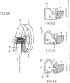
- FIG. 5A is a schematic configuration diagram of the space of the scroll part in which the exhaust gas flows.
- FIG. 5B, FIG. 5C and FIG. 5D show schematic configuration diagrams of the turbine housing 5 at respective positions Q, R, and S of the offset tongue portion 8 as viewed from the direction of arrow U in FIG. 5A .
- Reference numeral 9 denotes a flow passage formed by the turbine housing 5 for letting the exhaust gas flow into the scroll part 1 from the exhaust gas inlet.
- Reference numeral 8 denotes a connecting part between the flow passage 3 and the scroll part 1; it is the tongue portion and separates the flow passage from the blade side passage 4.
- the tongue portion 8 is offset along the axis line L1 of the rotating shaft (rotor shaft of FIG. 6 ) of the turbine rotor relative to the blade side passage 4 by an offset amount J, which is decreased from the proximal end toward the distal end edge 81 of the tongue portion 8 where the offset amount is zero.
- the position and width V of the outer circumferential part 91 of the flow passage 9 are not changed in this embodiment, and only part of the tongue portion 8 and the inner circumferential wall of the scroll part 1 are offset.
- the cross-sectional shape of the offset tongue portion changes from the normal shape shown by dotted lines to the shape shown by solid lines.
- the cross-sectional area of the flow passage 7 formed by the turbine housing 5 remains the same but the shape changes along the axis line L1 from the position drawn by dotted lines by the offset amount J (J1, J2).
- the offset amount J1 in cross section Q and the offset amount J2 in cross section R are set such that the condition J1 > J2 is met, and the offset amount in cross section S is zero.
- the width of the cut-out portion P3 shown in FIG. 5B, FIG. 5C, and FIG. 5D becomes progressively larger, i.e., PQ ⁇ PR ⁇ PS.
- the width of the cut-out portion P3 formed in the tongue portion 8 in FIG. 5A increases smoothly from the proximal end position (exhaust gas inlet side) of the cut-out length F toward the distal end edge 81 of the tongue portion 8, and it is the same as the width of the blade side passage 4 at the distal end edge 81.
- the advantageous effects of this embodiment are that, in addition to the effects of the first and second embodiments, the amount of deformation on the outer circumferential side of the scroll part is reduced to prevent difficulties when installing to the engine, as well as to promote heat dissipation from the tongue portion.
- the invention can suitably be applied to radial turbines, which are used in internal combustion engines or the like and configured to rotate the turbine rotor by introducing a fluid radially from a spiral scroll part to exert a force on the blades, then discharging the fluid axially, for improving the output of the internal combustion engine.
Landscapes
- Engineering & Computer Science (AREA)
- Mechanical Engineering (AREA)
- General Engineering & Computer Science (AREA)
- Chemical & Material Sciences (AREA)
- Chemical Kinetics & Catalysis (AREA)
- General Chemical & Material Sciences (AREA)
- Combustion & Propulsion (AREA)
- Supercharger (AREA)
Applications Claiming Priority (2)
| Application Number | Priority Date | Filing Date | Title |
|---|---|---|---|
| JP2010291359A JP5433560B2 (ja) | 2010-12-27 | 2010-12-27 | タービンスクロール部構造 |
| PCT/JP2011/079154 WO2012090724A1 (ja) | 2010-12-27 | 2011-12-16 | タービンスクロール部構造 |
Publications (3)
| Publication Number | Publication Date |
|---|---|
| EP2617961A1 EP2617961A1 (en) | 2013-07-24 |
| EP2617961A4 EP2617961A4 (en) | 2018-01-03 |
| EP2617961B1 true EP2617961B1 (en) | 2019-05-01 |
Family
ID=46382837
Family Applications (1)
| Application Number | Title | Priority Date | Filing Date |
|---|---|---|---|
| EP11853195.3A Not-in-force EP2617961B1 (en) | 2010-12-27 | 2011-12-16 | Radial turbine |
Country Status (5)
| Country | Link |
|---|---|
| US (1) | US9328738B2 (enExample) |
| EP (1) | EP2617961B1 (enExample) |
| JP (1) | JP5433560B2 (enExample) |
| CN (1) | CN103261622B (enExample) |
| WO (1) | WO2012090724A1 (enExample) |
Families Citing this family (17)
| Publication number | Priority date | Publication date | Assignee | Title |
|---|---|---|---|---|
| EP2940270B1 (en) | 2012-12-27 | 2017-04-26 | Mitsubishi Heavy Industries, Ltd. | Variable-geometry turbocharger |
| CN105264236B (zh) * | 2013-11-22 | 2018-02-13 | 株式会社Ihi | 离心压缩机及增压器 |
| JP5870083B2 (ja) * | 2013-12-27 | 2016-02-24 | 三菱重工業株式会社 | タービン |
| CN105940203B (zh) * | 2014-02-28 | 2019-08-06 | 三菱重工发动机和增压器株式会社 | 金属板涡轮壳体 |
| CN105221334B (zh) * | 2014-06-12 | 2016-12-14 | 山西华旗风能科技有限公司 | 一种集风装置 |
| WO2016071959A1 (ja) * | 2014-11-04 | 2016-05-12 | 三菱重工業株式会社 | タービンハウジングおよびタービンハウジングの製造方法 |
| DE102015014900A1 (de) * | 2015-10-22 | 2017-04-27 | GM Global Technology Operations LLC (n. d. Ges. d. Staates Delaware) | Radialturbinengehäuse |
| JP6641584B2 (ja) * | 2016-03-30 | 2020-02-05 | 三菱重工エンジン&ターボチャージャ株式会社 | ターボチャージャー |
| EP3473832B1 (en) * | 2016-12-28 | 2021-09-01 | Mitsubishi Heavy Industries Engine & Turbocharger, Ltd. | Turbine and turbocharger |
| CN112236584B (zh) * | 2018-06-29 | 2022-05-10 | 株式会社Ihi | 涡轮机及增压器 |
| JP7084543B2 (ja) * | 2019-02-25 | 2022-06-14 | 三菱重工エンジン&ターボチャージャ株式会社 | タービンハウジングおよびターボチャージャ |
| CN112443362B (zh) * | 2019-08-29 | 2025-03-07 | 湖南天雁机械有限责任公司 | 减少涡舌激振力的涡轮箱结构 |
| DE202021106090U1 (de) * | 2021-11-08 | 2023-02-09 | BorgWarner Inc. | Turbinengehäuse für einen Abgasturbolader |
| US11891947B2 (en) | 2022-06-23 | 2024-02-06 | Pratt & Whitney Canada Corp. | Aircraft engine, gas turbine intake therefore, and method of guiding exhaust gasses |
| US11851202B1 (en) | 2022-06-23 | 2023-12-26 | Pratt & Whitney Canada Corp. | Aircraft engine, gas turbine intake therefore, and method of guiding exhaust gasses |
| US11821361B1 (en) | 2022-07-06 | 2023-11-21 | Pratt & Whitney Canada Corp. | Gas turbine intake for aircraft engine and method of inspection thereof |
| US12188364B2 (en) | 2022-07-06 | 2025-01-07 | Pratt & Whitney Canada Corp. | Damper segment for pressurized gas pipe of aircraft engine |
Family Cites Families (13)
| Publication number | Priority date | Publication date | Assignee | Title |
|---|---|---|---|---|
| US4530640A (en) * | 1982-09-29 | 1985-07-23 | Roto-Master, Inc. | Method and apparatus for wastegating turbocharged engine with divided exhaust system |
| JP3253978B2 (ja) | 1990-12-10 | 2002-02-04 | 雅弘 井上 | タービンスクロール |
| JP3586515B2 (ja) | 1996-06-20 | 2004-11-10 | 三菱重工業株式会社 | タービンスクロール |
| JPH10231706A (ja) * | 1997-02-19 | 1998-09-02 | Mitsubishi Heavy Ind Ltd | タービンスクロール |
| FR2801072B1 (fr) * | 1999-11-17 | 2002-11-08 | Renault | Turbocompresseur comportant des entrees de turbine alignees selon un plan radial |
| US6478553B1 (en) | 2001-04-24 | 2002-11-12 | General Motors Corporation | High thrust turbocharger rotor with ball bearings |
| JP3534728B2 (ja) * | 2001-10-19 | 2004-06-07 | 三菱重工業株式会社 | ラジアルタービンのスクロール構造 |
| US6742989B2 (en) | 2001-10-19 | 2004-06-01 | Mitsubishi Heavy Industries, Ltd. | Structures of turbine scroll and blades |
| DE50312707D1 (de) | 2003-03-19 | 2010-06-24 | Abb Turbo Systems Ag | Abgasturbinengehäuse |
| EP1650415A4 (en) * | 2003-07-29 | 2009-06-24 | Hino Motors Ltd | TURBOCHARGER |
| JP4485334B2 (ja) * | 2004-12-02 | 2010-06-23 | トヨタ自動車株式会社 | ターボチャージャのタービンハウジング |
| DE102007055507A1 (de) * | 2007-11-21 | 2009-06-04 | Georg Emanuel Koppenwallner | Schräglippenspirale |
| US8266906B2 (en) * | 2009-03-11 | 2012-09-18 | GM Global Technology Operations LLC | Asymmetric split-inlet turbine housing |
-
2010
- 2010-12-27 JP JP2010291359A patent/JP5433560B2/ja not_active Expired - Fee Related
-
2011
- 2011-12-16 WO PCT/JP2011/079154 patent/WO2012090724A1/ja not_active Ceased
- 2011-12-16 EP EP11853195.3A patent/EP2617961B1/en not_active Not-in-force
- 2011-12-16 CN CN201180052624.2A patent/CN103261622B/zh not_active Expired - Fee Related
- 2011-12-16 US US13/879,426 patent/US9328738B2/en not_active Expired - Fee Related
Non-Patent Citations (1)
| Title |
|---|
| None * |
Also Published As
| Publication number | Publication date |
|---|---|
| JP5433560B2 (ja) | 2014-03-05 |
| US20130266433A1 (en) | 2013-10-10 |
| CN103261622A (zh) | 2013-08-21 |
| US9328738B2 (en) | 2016-05-03 |
| CN103261622B (zh) | 2015-11-25 |
| WO2012090724A1 (ja) | 2012-07-05 |
| EP2617961A1 (en) | 2013-07-24 |
| EP2617961A4 (en) | 2018-01-03 |
| JP2012137068A (ja) | 2012-07-19 |
Similar Documents
| Publication | Publication Date | Title |
|---|---|---|
| EP2617961B1 (en) | Radial turbine | |
| US8096777B2 (en) | Mixed flow turbine or radial turbine | |
| JP5665486B2 (ja) | ツインスクロール型ターボチャージャのタービンハウジング | |
| EP2236754A2 (en) | Steam turbine rotor blade and corresponding steam turbine | |
| US8251650B2 (en) | Compressor housing | |
| JP7184878B2 (ja) | 排気ガスタービンのディフューザ | |
| JP6195308B2 (ja) | 軸流タービンのラビリンスシール装置およびこれを備えた排ガスタービン過給機 | |
| JP2008075536A (ja) | 遠心圧縮機 | |
| JP2008075536A5 (enExample) | ||
| KR101055231B1 (ko) | 터빈 하우징 | |
| JP6633761B2 (ja) | タービン及びターボチャージャ | |
| US9816395B2 (en) | Turbine housing | |
| JP5125718B2 (ja) | 遠心圧縮機 | |
| JP5398515B2 (ja) | ラジアルタービンの動翼 | |
| CN106968723B (zh) | 径向涡轮机、涡轮增压器和径向涡轮机涡轮机壳体的插入件 | |
| US9638058B2 (en) | Scroll portion structure for radial turbine or diagonal flow turbine | |
| US8870532B2 (en) | Exhaust hood diffuser | |
| JP5797724B2 (ja) | 排気ガスターボチャージャ | |
| JP7336026B2 (ja) | タービン及びこのタービンを備えるターボチャージャ | |
| EP3763924B1 (en) | Turbomachine | |
| US20250198310A1 (en) | Turbine | |
| JP7463498B2 (ja) | 流れが最適化された軸方向ディフューザ内へのウェイストゲート質量流の同心的な導入 |
Legal Events
| Date | Code | Title | Description |
|---|---|---|---|
| PUAI | Public reference made under article 153(3) epc to a published international application that has entered the european phase |
Free format text: ORIGINAL CODE: 0009012 |
|
| 17P | Request for examination filed |
Effective date: 20130419 |
|
| AK | Designated contracting states |
Kind code of ref document: A1 Designated state(s): AL AT BE BG CH CY CZ DE DK EE ES FI FR GB GR HR HU IE IS IT LI LT LU LV MC MK MT NL NO PL PT RO RS SE SI SK SM TR |
|
| DAX | Request for extension of the european patent (deleted) | ||
| RA4 | Supplementary search report drawn up and despatched (corrected) |
Effective date: 20171205 |
|
| RIC1 | Information provided on ipc code assigned before grant |
Ipc: F02C 6/12 20060101ALI20171129BHEP Ipc: F01D 9/02 20060101ALI20171129BHEP Ipc: F02B 39/00 20060101AFI20171129BHEP |
|
| RAP1 | Party data changed (applicant data changed or rights of an application transferred) |
Owner name: MITSUBISHI HEAVY INDUSTRIES ENGINE & TURBOCHARGER, |
|
| STAA | Information on the status of an ep patent application or granted ep patent |
Free format text: STATUS: EXAMINATION IS IN PROGRESS |
|
| 17Q | First examination report despatched |
Effective date: 20180907 |
|
| GRAP | Despatch of communication of intention to grant a patent |
Free format text: ORIGINAL CODE: EPIDOSNIGR1 |
|
| STAA | Information on the status of an ep patent application or granted ep patent |
Free format text: STATUS: GRANT OF PATENT IS INTENDED |
|
| INTG | Intention to grant announced |
Effective date: 20181129 |
|
| GRAS | Grant fee paid |
Free format text: ORIGINAL CODE: EPIDOSNIGR3 |
|
| GRAA | (expected) grant |
Free format text: ORIGINAL CODE: 0009210 |
|
| STAA | Information on the status of an ep patent application or granted ep patent |
Free format text: STATUS: THE PATENT HAS BEEN GRANTED |
|
| AK | Designated contracting states |
Kind code of ref document: B1 Designated state(s): AL AT BE BG CH CY CZ DE DK EE ES FI FR GB GR HR HU IE IS IT LI LT LU LV MC MK MT NL NO PL PT RO RS SE SI SK SM TR |
|
| REG | Reference to a national code |
Ref country code: GB Ref legal event code: FG4D |
|
| REG | Reference to a national code |
Ref country code: CH Ref legal event code: EP Ref country code: AT Ref legal event code: REF Ref document number: 1127204 Country of ref document: AT Kind code of ref document: T Effective date: 20190515 |
|
| REG | Reference to a national code |
Ref country code: DE Ref legal event code: R096 Ref document number: 602011058608 Country of ref document: DE |
|
| REG | Reference to a national code |
Ref country code: IE Ref legal event code: FG4D |
|
| REG | Reference to a national code |
Ref country code: NL Ref legal event code: FP |
|
| REG | Reference to a national code |
Ref country code: LT Ref legal event code: MG4D |
|
| PG25 | Lapsed in a contracting state [announced via postgrant information from national office to epo] |
Ref country code: FI Free format text: LAPSE BECAUSE OF FAILURE TO SUBMIT A TRANSLATION OF THE DESCRIPTION OR TO PAY THE FEE WITHIN THE PRESCRIBED TIME-LIMIT Effective date: 20190501 Ref country code: NO Free format text: LAPSE BECAUSE OF FAILURE TO SUBMIT A TRANSLATION OF THE DESCRIPTION OR TO PAY THE FEE WITHIN THE PRESCRIBED TIME-LIMIT Effective date: 20190801 Ref country code: LT Free format text: LAPSE BECAUSE OF FAILURE TO SUBMIT A TRANSLATION OF THE DESCRIPTION OR TO PAY THE FEE WITHIN THE PRESCRIBED TIME-LIMIT Effective date: 20190501 Ref country code: HR Free format text: LAPSE BECAUSE OF FAILURE TO SUBMIT A TRANSLATION OF THE DESCRIPTION OR TO PAY THE FEE WITHIN THE PRESCRIBED TIME-LIMIT Effective date: 20190501 Ref country code: ES Free format text: LAPSE BECAUSE OF FAILURE TO SUBMIT A TRANSLATION OF THE DESCRIPTION OR TO PAY THE FEE WITHIN THE PRESCRIBED TIME-LIMIT Effective date: 20190501 Ref country code: PT Free format text: LAPSE BECAUSE OF FAILURE TO SUBMIT A TRANSLATION OF THE DESCRIPTION OR TO PAY THE FEE WITHIN THE PRESCRIBED TIME-LIMIT Effective date: 20190901 Ref country code: AL Free format text: LAPSE BECAUSE OF FAILURE TO SUBMIT A TRANSLATION OF THE DESCRIPTION OR TO PAY THE FEE WITHIN THE PRESCRIBED TIME-LIMIT Effective date: 20190501 Ref country code: SE Free format text: LAPSE BECAUSE OF FAILURE TO SUBMIT A TRANSLATION OF THE DESCRIPTION OR TO PAY THE FEE WITHIN THE PRESCRIBED TIME-LIMIT Effective date: 20190501 |
|
| PG25 | Lapsed in a contracting state [announced via postgrant information from national office to epo] |
Ref country code: BG Free format text: LAPSE BECAUSE OF FAILURE TO SUBMIT A TRANSLATION OF THE DESCRIPTION OR TO PAY THE FEE WITHIN THE PRESCRIBED TIME-LIMIT Effective date: 20190801 Ref country code: LV Free format text: LAPSE BECAUSE OF FAILURE TO SUBMIT A TRANSLATION OF THE DESCRIPTION OR TO PAY THE FEE WITHIN THE PRESCRIBED TIME-LIMIT Effective date: 20190501 Ref country code: RS Free format text: LAPSE BECAUSE OF FAILURE TO SUBMIT A TRANSLATION OF THE DESCRIPTION OR TO PAY THE FEE WITHIN THE PRESCRIBED TIME-LIMIT Effective date: 20190501 Ref country code: GR Free format text: LAPSE BECAUSE OF FAILURE TO SUBMIT A TRANSLATION OF THE DESCRIPTION OR TO PAY THE FEE WITHIN THE PRESCRIBED TIME-LIMIT Effective date: 20190802 |
|
| REG | Reference to a national code |
Ref country code: AT Ref legal event code: MK05 Ref document number: 1127204 Country of ref document: AT Kind code of ref document: T Effective date: 20190501 |
|
| PG25 | Lapsed in a contracting state [announced via postgrant information from national office to epo] |
Ref country code: IS Free format text: LAPSE BECAUSE OF FAILURE TO SUBMIT A TRANSLATION OF THE DESCRIPTION OR TO PAY THE FEE WITHIN THE PRESCRIBED TIME-LIMIT Effective date: 20190901 |
|
| PG25 | Lapsed in a contracting state [announced via postgrant information from national office to epo] |
Ref country code: RO Free format text: LAPSE BECAUSE OF FAILURE TO SUBMIT A TRANSLATION OF THE DESCRIPTION OR TO PAY THE FEE WITHIN THE PRESCRIBED TIME-LIMIT Effective date: 20190501 Ref country code: SK Free format text: LAPSE BECAUSE OF FAILURE TO SUBMIT A TRANSLATION OF THE DESCRIPTION OR TO PAY THE FEE WITHIN THE PRESCRIBED TIME-LIMIT Effective date: 20190501 Ref country code: AT Free format text: LAPSE BECAUSE OF FAILURE TO SUBMIT A TRANSLATION OF THE DESCRIPTION OR TO PAY THE FEE WITHIN THE PRESCRIBED TIME-LIMIT Effective date: 20190501 Ref country code: DK Free format text: LAPSE BECAUSE OF FAILURE TO SUBMIT A TRANSLATION OF THE DESCRIPTION OR TO PAY THE FEE WITHIN THE PRESCRIBED TIME-LIMIT Effective date: 20190501 Ref country code: EE Free format text: LAPSE BECAUSE OF FAILURE TO SUBMIT A TRANSLATION OF THE DESCRIPTION OR TO PAY THE FEE WITHIN THE PRESCRIBED TIME-LIMIT Effective date: 20190501 Ref country code: CZ Free format text: LAPSE BECAUSE OF FAILURE TO SUBMIT A TRANSLATION OF THE DESCRIPTION OR TO PAY THE FEE WITHIN THE PRESCRIBED TIME-LIMIT Effective date: 20190501 |
|
| PGFP | Annual fee paid to national office [announced via postgrant information from national office to epo] |
Ref country code: DE Payment date: 20191203 Year of fee payment: 9 |
|
| REG | Reference to a national code |
Ref country code: DE Ref legal event code: R097 Ref document number: 602011058608 Country of ref document: DE |
|
| PG25 | Lapsed in a contracting state [announced via postgrant information from national office to epo] |
Ref country code: IT Free format text: LAPSE BECAUSE OF FAILURE TO SUBMIT A TRANSLATION OF THE DESCRIPTION OR TO PAY THE FEE WITHIN THE PRESCRIBED TIME-LIMIT Effective date: 20190501 Ref country code: SM Free format text: LAPSE BECAUSE OF FAILURE TO SUBMIT A TRANSLATION OF THE DESCRIPTION OR TO PAY THE FEE WITHIN THE PRESCRIBED TIME-LIMIT Effective date: 20190501 |
|
| PLBE | No opposition filed within time limit |
Free format text: ORIGINAL CODE: 0009261 |
|
| STAA | Information on the status of an ep patent application or granted ep patent |
Free format text: STATUS: NO OPPOSITION FILED WITHIN TIME LIMIT |
|
| PG25 | Lapsed in a contracting state [announced via postgrant information from national office to epo] |
Ref country code: TR Free format text: LAPSE BECAUSE OF FAILURE TO SUBMIT A TRANSLATION OF THE DESCRIPTION OR TO PAY THE FEE WITHIN THE PRESCRIBED TIME-LIMIT Effective date: 20190501 |
|
| 26N | No opposition filed |
Effective date: 20200204 |
|
| PG25 | Lapsed in a contracting state [announced via postgrant information from national office to epo] |
Ref country code: PL Free format text: LAPSE BECAUSE OF FAILURE TO SUBMIT A TRANSLATION OF THE DESCRIPTION OR TO PAY THE FEE WITHIN THE PRESCRIBED TIME-LIMIT Effective date: 20190501 |
|
| PGFP | Annual fee paid to national office [announced via postgrant information from national office to epo] |
Ref country code: GB Payment date: 20191213 Year of fee payment: 9 |
|
| PG25 | Lapsed in a contracting state [announced via postgrant information from national office to epo] |
Ref country code: SI Free format text: LAPSE BECAUSE OF FAILURE TO SUBMIT A TRANSLATION OF THE DESCRIPTION OR TO PAY THE FEE WITHIN THE PRESCRIBED TIME-LIMIT Effective date: 20190501 |
|
| REG | Reference to a national code |
Ref country code: CH Ref legal event code: PL |
|
| REG | Reference to a national code |
Ref country code: BE Ref legal event code: MM Effective date: 20191231 |
|
| PG25 | Lapsed in a contracting state [announced via postgrant information from national office to epo] |
Ref country code: MC Free format text: LAPSE BECAUSE OF FAILURE TO SUBMIT A TRANSLATION OF THE DESCRIPTION OR TO PAY THE FEE WITHIN THE PRESCRIBED TIME-LIMIT Effective date: 20190501 |
|
| PG25 | Lapsed in a contracting state [announced via postgrant information from national office to epo] |
Ref country code: LU Free format text: LAPSE BECAUSE OF NON-PAYMENT OF DUE FEES Effective date: 20191216 Ref country code: IE Free format text: LAPSE BECAUSE OF NON-PAYMENT OF DUE FEES Effective date: 20191216 |
|
| PG25 | Lapsed in a contracting state [announced via postgrant information from national office to epo] |
Ref country code: CH Free format text: LAPSE BECAUSE OF NON-PAYMENT OF DUE FEES Effective date: 20191231 Ref country code: LI Free format text: LAPSE BECAUSE OF NON-PAYMENT OF DUE FEES Effective date: 20191231 Ref country code: BE Free format text: LAPSE BECAUSE OF NON-PAYMENT OF DUE FEES Effective date: 20191231 |
|
| PGFP | Annual fee paid to national office [announced via postgrant information from national office to epo] |
Ref country code: NL Payment date: 20201113 Year of fee payment: 10 |
|
| PGFP | Annual fee paid to national office [announced via postgrant information from national office to epo] |
Ref country code: FR Payment date: 20201112 Year of fee payment: 10 |
|
| PG25 | Lapsed in a contracting state [announced via postgrant information from national office to epo] |
Ref country code: CY Free format text: LAPSE BECAUSE OF FAILURE TO SUBMIT A TRANSLATION OF THE DESCRIPTION OR TO PAY THE FEE WITHIN THE PRESCRIBED TIME-LIMIT Effective date: 20190501 |
|
| REG | Reference to a national code |
Ref country code: DE Ref legal event code: R119 Ref document number: 602011058608 Country of ref document: DE |
|
| PG25 | Lapsed in a contracting state [announced via postgrant information from national office to epo] |
Ref country code: HU Free format text: LAPSE BECAUSE OF FAILURE TO SUBMIT A TRANSLATION OF THE DESCRIPTION OR TO PAY THE FEE WITHIN THE PRESCRIBED TIME-LIMIT; INVALID AB INITIO Effective date: 20111216 Ref country code: MT Free format text: LAPSE BECAUSE OF FAILURE TO SUBMIT A TRANSLATION OF THE DESCRIPTION OR TO PAY THE FEE WITHIN THE PRESCRIBED TIME-LIMIT Effective date: 20190501 |
|
| GBPC | Gb: european patent ceased through non-payment of renewal fee |
Effective date: 20201216 |
|
| PG25 | Lapsed in a contracting state [announced via postgrant information from national office to epo] |
Ref country code: GB Free format text: LAPSE BECAUSE OF NON-PAYMENT OF DUE FEES Effective date: 20201216 Ref country code: DE Free format text: LAPSE BECAUSE OF NON-PAYMENT OF DUE FEES Effective date: 20210701 |
|
| PG25 | Lapsed in a contracting state [announced via postgrant information from national office to epo] |
Ref country code: MK Free format text: LAPSE BECAUSE OF FAILURE TO SUBMIT A TRANSLATION OF THE DESCRIPTION OR TO PAY THE FEE WITHIN THE PRESCRIBED TIME-LIMIT Effective date: 20190501 |
|
| REG | Reference to a national code |
Ref country code: NL Ref legal event code: MM Effective date: 20220101 |
|
| PG25 | Lapsed in a contracting state [announced via postgrant information from national office to epo] |
Ref country code: NL Free format text: LAPSE BECAUSE OF NON-PAYMENT OF DUE FEES Effective date: 20220101 |
|
| PG25 | Lapsed in a contracting state [announced via postgrant information from national office to epo] |
Ref country code: FR Free format text: LAPSE BECAUSE OF NON-PAYMENT OF DUE FEES Effective date: 20211231 |