EP2236754A2 - Steam turbine rotor blade and corresponding steam turbine - Google Patents
Steam turbine rotor blade and corresponding steam turbine Download PDFInfo
- Publication number
- EP2236754A2 EP2236754A2 EP10153973A EP10153973A EP2236754A2 EP 2236754 A2 EP2236754 A2 EP 2236754A2 EP 10153973 A EP10153973 A EP 10153973A EP 10153973 A EP10153973 A EP 10153973A EP 2236754 A2 EP2236754 A2 EP 2236754A2
- Authority
- EP
- European Patent Office
- Prior art keywords
- moving blade
- shroud
- outer circumferential
- turbine
- flare angle
- Prior art date
- Legal status (The legal status is an assumption and is not a legal conclusion. Google has not performed a legal analysis and makes no representation as to the accuracy of the status listed.)
- Withdrawn
Links
Images


Classifications
-
- F—MECHANICAL ENGINEERING; LIGHTING; HEATING; WEAPONS; BLASTING
- F01—MACHINES OR ENGINES IN GENERAL; ENGINE PLANTS IN GENERAL; STEAM ENGINES
- F01D—NON-POSITIVE DISPLACEMENT MACHINES OR ENGINES, e.g. STEAM TURBINES
- F01D5/00—Blades; Blade-carrying members; Heating, heat-insulating, cooling or antivibration means on the blades or the members
- F01D5/12—Blades
- F01D5/22—Blade-to-blade connections, e.g. for damping vibrations
- F01D5/225—Blade-to-blade connections, e.g. for damping vibrations by shrouding
-
- F—MECHANICAL ENGINEERING; LIGHTING; HEATING; WEAPONS; BLASTING
- F01—MACHINES OR ENGINES IN GENERAL; ENGINE PLANTS IN GENERAL; STEAM ENGINES
- F01D—NON-POSITIVE DISPLACEMENT MACHINES OR ENGINES, e.g. STEAM TURBINES
- F01D5/00—Blades; Blade-carrying members; Heating, heat-insulating, cooling or antivibration means on the blades or the members
- F01D5/12—Blades
- F01D5/14—Form or construction
- F01D5/141—Shape, i.e. outer, aerodynamic form
- F01D5/142—Shape, i.e. outer, aerodynamic form of the blades of successive rotor or stator blade-rows
- F01D5/143—Contour of the outer or inner working fluid flow path wall, i.e. shroud or hub contour
-
- F—MECHANICAL ENGINEERING; LIGHTING; HEATING; WEAPONS; BLASTING
- F05—INDEXING SCHEMES RELATING TO ENGINES OR PUMPS IN VARIOUS SUBCLASSES OF CLASSES F01-F04
- F05D—INDEXING SCHEME FOR ASPECTS RELATING TO NON-POSITIVE-DISPLACEMENT MACHINES OR ENGINES, GAS-TURBINES OR JET-PROPULSION PLANTS
- F05D2220/00—Application
- F05D2220/30—Application in turbines
- F05D2220/31—Application in turbines in steam turbines
-
- F—MECHANICAL ENGINEERING; LIGHTING; HEATING; WEAPONS; BLASTING
- F05—INDEXING SCHEMES RELATING TO ENGINES OR PUMPS IN VARIOUS SUBCLASSES OF CLASSES F01-F04
- F05D—INDEXING SCHEME FOR ASPECTS RELATING TO NON-POSITIVE-DISPLACEMENT MACHINES OR ENGINES, GAS-TURBINES OR JET-PROPULSION PLANTS
- F05D2250/00—Geometry
- F05D2250/20—Three-dimensional
- F05D2250/23—Three-dimensional prismatic
- F05D2250/232—Three-dimensional prismatic conical
Abstract
Description
- The present invention relates to a turbine moving blade applied to a steam turbine.
- In general, a steam turbine includes a plurality of stages each composed of a moving blade and a stator vane axially provided on a turbine rotor. In addition, the steam turbine is provided, on an outer circumferential portion of an outlet of its final stage, with a flow guide portion adapted to lead steam into an exhaust hood. Such a steam turbine is operated such that the stator vane formed as a restrictive passage accelerates steam to increase its kinetic energy and the moving blade converts the kinetic energy into rotational energy to generate power. Then, some of the steam is turned in an extraction channel in a rotor-radial direction and rest of the steam is discharged into the exhaust hood. See
JP-2003-27901-A - Since shortening the length of a turbine shaft in such a steam turbine can reduce a difference in an axial thermal extension of the turbine rotor, the effects of reducing loss resulting from leakage flow and improving reliability in turbine shaft vibration can be expected.
- The axial length of a low-pressure turbine depends on a position at which the radial turning of a flow guide provided at the downstream end of an external stationary wall of a final stage terminates. Therefore, if the curvature of the flow guide portion is increased, the radial turning of the flow guide portion can be terminated on the more upstream side in a steam flow direction (hereinafter, simply described as the upstream side). Thus, the length of the turbine shaft can be reduced. However, the exhaust chamber is formed as a diffuser path, which has an inverse pressure gradient. Because of this, if the curvature of the flow guide portion is increased to increase a flare angle of the flow guide portion, separation of a steam flow from the flow guide portion is likely to occur, which may probably cause a flow loss. Incidentally, the above-mentioned flare angle means an angle formed between a steam passage outer circumferential wall and a turbine central axis.
- In addition, it is necessary to radially turn the stream flow in a shorter shaft length by reducing the turbine shaft length. Therefore, in an extraction stage provided on the upstream side of the low-pressure turbine, a deviation is increased between a flare angle of a shroud inner circumferential surface of a blade constituting the extraction stage and a flare angle of an outer circumferential side stationary wall inner circumferential surface adjacently provided on the moving blade downstream side. In addition, a distance between the moving blade outlet and the extraction path is reduced and the steam flow is radially turned in a shorter distance between the moving blade outlet and the extraction path inlet. Thus, a separation swirl is likely to occur at the extraction path inlet, which may probably cause a flow loss.
- Accordingly, it is an object of the present invention to provide a steam turbine moving blade that can reduce the length of a turbine shaft while suppressing occurrence of a loss resulting from flow separation and from a secondary flow to suppress a decrease in turbine efficiency.
- To solve the above object, according to an aspect of the present invention, there is provided a moving blade for a steam turbine, the moving blade having a shroud formed at an outer circumferential side distal end, wherein the shroud has an inner circumferential surface so formed that a moving blade outlet flare angle is greater than a moving blade inlet flare angle, the moving blade inlet flare angle is generally equal to a moving blade upstream side flare angle of an outer circumferential side stationary wall adjacently provided on an upstream side of the shroud; and/or the moving blade outlet flare angle is generally equal to a moving blade downstream side flare angle of the outer circumferential side stationary wall adjacently provided on a downstream side of the shroud. More specifically, the moving blade and the steam turbine are each configured as recited in corresponding claims.
- The present invention can reduce the length of a turbine shaft while suppressing occurrence of a loss resulting from flow separation and from a secondary flow to suppress a decrease in turbine efficiency.
-
-
Figs. 1A and 1B are cross-sectional views of an essential portion of a final stage of a steam turbine according to a first embodiment of the present invention. -
Figs. 2A and 2B are cross-sectional views of an essential portion of a final stage of a steam turbine according to a second embodiment of the present invention. -
Figs. 3A and 3B are cross-sectional views of an essential portion of an extraction stage of a steam turbine according to a third embodiment of the present invention. -
Figs. 4A, 4B and 4C are cross-sectional views of an essential portion of an extraction stage of a traditional steam turbine. -
Figs. 5A and 5B are cross-sectional views of an essential portion of an extraction stage of a steam turbine according to a fourth embodiment of the present invention. -
Figs. 6A and 6B are cross-sectional views of an essential portion of an extraction stage of a steam turbine according to a fifth embodiment of the present invention. - Preferred embodiments of the present invention will hereinafter be described in detail with reference to the drawings. Incidentally, like or corresponding elements are denoted with like reference numerals over the drawings.
- A description is given of a first embodiment of the present invention.
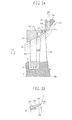
Fig. 1A illustrates a configuration of an essential portion of a final stage and an exhaust hood of a low-pressure turbine as viewed from the side. Astator vane 2 and a movingblade 1 are paired to constitute a turbine final stage. An outer circumferential end of thestator vane 2 is supported by an outer circumferential side stationary wall 4 and an inner circumferential end is supported by an inner circumferentialside stator wall 5. A plurality of thestator vanes 2 are provided in a circumferential direction. On the other hand, a plurality of the movingblades 1 are circumferentially secured to a turbine rotor 7. Ashroud 3 is provided at outer circumferential side distal ends of the movingblades 1 so as to connect together the plurality of moving blades provided in a rotor circumferential direction. Types of theshroud 3 include a type in which a plurality of moving blades are assembled and secured by a single member and a type in which covers each having an inter-blade pitch are arranged for the respective moving blades and circumferentially press fitted thereto by torsion of the blade due to rotation. Theshroud 3 used in the present embodiment may be any one of these types. - Arrow 51 in
Fig. 1A denotes a flow direction of steam in asteam path 19 defined between the outer circumferential side stationary wall 4 and the inner circumferential sidestationary wall 5. In the following, a downstream side in a flow direction of steam is simply called the downstream side and an upstream side in the flow direction of steam is simply called the upstream side. - A casing 9 for covering the outer circumferential side stationary wall 4 is provided on a turbine-radially outer circumferential side (hereinafter, simply described as the outer circumferential side) of the outer circumferential side stationary wall 4. An
exhaust hood 12 is defined between the outer circumferential side stationary wall 4 and the casing 9. A flow guide portion 11 adapted to lead steam leaving the movingblade 1 to theexhaust hood 12 is formed at the downstream side end portion of the outer circumferential side stationary wall 4. Abearing cone 10 is provided on a turbine-radially inner circumferential side (hereinafter, simply called the inner circumferential side) of the flow guide portion 11. In this way, anannular diffuser path 18 is defined between thebearing cone 10 and the flow guide portion 11. - The flow guide portion 11 and the
bearing cone 10 are each bent in the turbine-radial direction. Thediffuser path 18 communicates with theexhaust hood 12. Thus, the steam having passed through the finalstage moving blade 1 passes through thediffuser path 18. While the flowing direction is turned from the axial direction to the radial direction, the steam decelerates so that energy according to the deceleration is converted to pressure to recover pressure. Then, the steam is led to the exhaust hood. After having led to theexhaust hood 12, the steam is introduced into a condenser (not illustrated) communicating with the exhaust hood. - A description is next given of a structure of the
shroud 3. Hereinafter, a flare angle is defined as an angle formed between an outer circumferential wall of asteam path 19 and a turbinecentral axis 50. The outer circumferential wall of thesteam path 19 means e.g. an innercircumferential wall surface 13 of the outer circumferential side stationary wall 4, an innercircumferential surface 14 of theshroud 3 or an inner circumferential surface 15 of the flow guide portion 11. - Referring to
Fig. 1B , the innercircumferential surface 14 of theshroud 3 is formed to be radially smoothly bent so that the flare angle is gradually increased from the upstream side toward the downstream side. An angle of a tangential line A (indicated with a broken line) located at an upstream side end of the innercircumferential surface 14 with respect to the turbinecentral axis 50 is referred to as a moving blade inlet flare angle α2. An angle of a tangential line B (indicated with a broken line) extending from a downstream side end of the innercircumferential surface 14 with respect to the turbinecentral axis 50 is referred to as a moving blade outlet flare angle α3. The innercircumferential surface 14 of theshroud 3 in the present embodiment is formed such that the moving blade outlet flare angle α3 is greater than the moving blade inlet flare angle α2. - An angle formed between the inner
circumferential surface 13 of the outer circumferential side stationary wall 4 constituting the final stage and the turbinecentral axis 50 is referred to as a moving blade upstream side flare angle α1. The flow guide portion 11 is formed to be radially smoothly bent so that the flare angle is gradually increased from the upstream side toward the downstream side. An angle formed between the turbinecentral axis 50 and a tangential line (indicated with a broken line) extending from a curvature start point C of the inner circumferential surface 15 of theflow guide portion 50 is referred to as a moving blade downstream side flare angle α4. In the present embodiment, the innercircumferential surface 14 of theshroud 3 is formed as below. The moving blade inlet flare angle α2 is generally equal to the moving blade upstream side flare angle α1 of the outer circumferential side stationary wall 4 adjacently provided on the moving blade upstream side. In addition, the moving blade outlet flare angle α3 is generally equal to the moving blade downstream side flare angle α4 of the floor guide portion 11 of the outer circumferential side stationary wall adjacently provided on the moving blade downstream side. - On the other hand, the outer circumferential surface of the
shroud 3 has aninclination surface 16 on the upstream side and aparallel surface 17 parallel to the turbinecentral axis 50 on the downstream side. A shroud upstream side outer diameter is made smaller than a shroud downstream side outer diameter. The shroud upstream side outer diameter is a distance from the turbinecentral axis 50 to the upstream side end of the outer circumferential surface of theshroud 3. The shroud downstream side outer diameter is a distance from the turbinecentral axis 50 to the downstream side end of the outer circumferential surface of theshroud 3. Incidentally, the inclination angle of theinclination surface 16 is set such that theshroud 3 has a thickness generally uniform from the upstream side to the downstream side. - Seal fins 6 are provided on the outer circumferential side stationary wall 4 opposite the
parallel surface 17 of the outer circumferential surface of theshroud 3. This narrows a gap between the outer circumferential side stationary wall 4 and theshroud 3 to suppress leakage of a steam flow getting around the movingblade 1. Incidentally, in the turbine final stage, a leakage passage area defined between the seal fins and the shroud is smaller than the passage area of the moving blade. Therefore, the seal fins 6 may be provided only on the moving blade outlet side. - A description is given of a function and effect of the present embodiment. The inner
circumferential surface 14 of theshroud 3 is formed such that the moving blade inlet flare angle α2 is generally equal to the moving blade upstream side flare angle α1 and the moving blade outlet flare angle α3 is generally equal to the moving blade downstream side flare angle α4. Therefore, steam flows parallel to the inner circumferential surface from the outer circumferential side stationary wall 4 to theshroud 3. The steam flows parallel to the inner circumferential surface from theshroud 3 to the flow guide portion 11. The flow of steam is radially smoothly turned between the stator vane and the moving blade and between the moving blade and the flow guide portion. Thus, occurrence of a loss resulting from flow separation and from a secondary flow can be suppressed, which can suppress the lowering of turbine efficiency. - In the present invention, it is preferred that the moving blade inlet flare angle α2 be equal to the moving blade upstream side flare angle α1 and the moving blade outlet flare angle α3 be equal to the moving blade downstream side flare angle α4. However, if respective deviations of the flare angles are generally equal to each other, i.e., if each of the deviations falls within 5°, achievement of the effect of the present invention can be expected.
- The internal
circumferential surface 14 of theshroud 3 is formed such that the moving blade outlet flare angle α3 is greater than the moving blade inlet flare angle α2 so as to allow also the movingblade 1 to take on a share of the radial turning of steam. The steam on the moving blade shroud side of the low-pressure turbine final stage has high-speed and large kinetic energy. Conventionally, this high-speed steam has radially been turned mainly by thediffuser path 18 and theexhaust hood 12 having an inverse pressure gradient. In the present invention, the radial turning of steam is shared by the inside of the moving blade at which steam speed is slower and the kinetic energy is smaller than at the outlet of the moving blade. Therefore, a radially turning amount of steam flow in theexhaust hood 12 can be made smaller than ever before. Consequently, if the radius of curvature of the inner circumferential surface 15 of the flow guide portion 11 is equal to the traditional one, i.e., if separation occurrence potential of the passage shape is generally equal to the traditional one, the shaft length to a position where steam is radially turned can be reduced. - The increase in flare angle due to the reduced length of the turbine shaft increases the curvature of the
shroud 3, i.e., increases the difference between the moving blade outlet flare angle α3 and the moving blade inlet flare angle α2. However, theinclination surface 16 is formed on the upstream side of the outer circumferential surface of theshroud 3 and theparallel surface 17 is formed on the downstream side in parallel to the central axis. This makes the upstream side outer diameter smaller than the downstream side outer diameter. The above-mentioned upstream side outer diameter corresponds to the distance from the turbinecentral axis 50 to the upstream side distal end of the outer circumferential surface of theshroud 3. In addition, the above-mentioned downstream side outer diameter corresponds to the distance from the turbinecentral axis 50 to the downstream side distal end of the outer circumferential surface of theshroud 3. Thus, the weight increase of the shroud per se can be suppressed. As a result, it is possible to prevent the strength reliability of the turbine blade from lowering. - A description is next given of a second embodiment of the present invention.
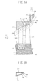
Fig. 2A illustrates a structure of an essential portion of a final stage and an exhaust hood of a low-pressure turbine as viewed from the side. Incidentally, the same elements as in the first embodiment are denoted with like reference numerals and their explanations are omitted. - In the present embodiment, an inner circumferential surface downstream side end portion of an outer circumferential side stationary wall 4 supporting a
stator vane 2 of a final stage is formed parallel to a turbinecentral axis 50. In addition, a moving blade upstream side flare angle α1 is formed at an approximately 0 degree at an outlet of the outer circumferential side stationary wall 4. On the other hand, an inner circumferential surface of ashroud 3 is composed of an upstream sideparallel surface 21 parallel to the turbinecentral axis 50 and a downstreamside inclination surface 22. Incidentally, the upstream side end portion of the inner circumferential surface is included in theparallel surface 21 and the downstream side end portion is included in theinclination surface 22. - A moving blade inlet flare angle and a moving blade outlet flare angle are defined as below. If the upstream side end portion of the inner circumferential surface is included in a plane (precisely, curve-shaped in a circumferential direction and straight line-shaped in an axial direction, hereinafter, simply described as the plane), an angle formed between the plane including the upstream side end portion and the central axis, i.e., an angle formed between a cross-line which the plane including the upstream side end portion crosses with a turbine meridian plane and the central axis, is referred to as the moving blade inlet flare angle. If the downstream side end portion of the inner circumferential surface is included in the plane, an angle formed between the plane including the downstream side end portion and the central axis i.e., an angle formed between a cross-line which the plane including the downstream side end portion crosses with a turbine meridian plane and the central axis, is referred to as the moving blade outlet flare angle. Thus, in the present embodiment, an angle formed between the
parallel surface 21 and the turbinecentral axis 50 is defined as a moving blade inlet flare angle α2. An angle formed between theinclination surface 22 and the turbinecentral axis 50 is defined as a moving blade outlet flare angle α3. - In the present embodiment, the inner circumferential surface of the
shroud 3 is such that the moving blade inlet flare angle α2 is generally equal to a moving blade upstream side flare angle α1 and the moving blade outlet flare angle α3 is generally equal to a moving blade downstream side flare angle α4 of a floor guide portion 11. In addition, the moving blade outlet flare angle α3 is formed to be greater than the moving blade inlet flare angle α2. Incidentally, as shown inFig. 2A , the inner circumferential surface 15 of the floor guide portion 11 is formed to be tilted at a given angle relative to the central axis from the upstream side toward the downstream side without being radially bent. In this case, the tilted angle of the inner circumferential surface 15 of the floor guide portion 11 is formed as the moving blade downstream side flare angle α4. - The outer circumferential surface of the
shroud 3 has an upper stream sideparallel surface 23 being parallel to the turbinecentral axis 50 and including an upstream side end, a downstream sideparallel surface 25 being parallel to the turbinecentral axis 50 and including a downstream side end, and aninclination surface 24 inclined relative to the turbinecentral axis 50 and connecting the upstream side parallel surface with the downstream side parallel surface. Theshroud 3 is formed such that its upstream side outer diameter is smaller than its downstream side outer diameter. The upstream side outer diameter is a distance from the turbinecentral axis 50 to the upstream side distal end of the outer circumferential surface of theshroud 3. The downstream side outer diameter is a distance from the turbinecentral axis 50 to the downstream side distal end of the outer circumferential surface of theshroud 3. In addition, theshroud 3 is formed to have a generally constant thickness from the upstream side to the downstream side. - In the present embodiment, the inner
circumferential surface 14 of theshroud 3 is formed as below. The moving blade inlet flare angle α2 is generally equal to the moving blade upstream side flare angle α1. The moving blade outlet flare angle α3 is generally equal to the moving blade downstream side flare angle α4. Further, the moving blade outlet flare angle α3 is greater than the moving blade inlet flare angle α2. Therefore,steam 20 flows between the innercircumferential surface 14 of theshroud 3 and the innercircumferential surface 13 of the outer circumferential side stationary wall 4 and between the innercircumferential surface 14 of theshroud 3 and the inner circumferential surface 15 of the flow guide portion 11, in general parallel to the inner circumferential surfaces. Thus, occurrence of a loss resulting from steam flow separation and from a secondary flow can be suppressed, which can suppress the lowering of turbine efficiency. - Incidentally, also in the present embodiment, it is preferred that the moving blade inlet flare angle α2 be equal to the moving blade upstream side flare angle α1 and the moving blade outlet flare angle α3 be equal to the moving blade downstream side flare angle α4. However, if respective deviations of the flare angles are generally equal to each other, i.e., if each of the deviations falls within 5°, achievement of the effect of the present invention can be expected.
- It is possible to turn the steam flow in the radial direction between the inlet and outlet of the moving
blade 2. It is possible to make the amount of radially turning steam flow smaller than ever before in theexhaust hood 12 including the flow guide portion 11 having high separation potential due to inverse pressure gradient. As a result, if the curvature radius of the inner circumferential surface 15 of the flow guide portion 11 is equal to the traditional one, i.e., if the separation occurrence potential of the passage shape is general equal to the traditional one, it is possible to reduce the shaft length to the radial turn. - The upstream side outer diameter which is the distance from the turbine
central axis 50 to the upstream side distal end of the outer circumferential surface of theshroud 3 is made smaller than the downstream side outer diameter which is the distance from the turbinecentral axis 50 to the downstream side distal end of the outer circumferential surface of theshroud 3. Therefore, even if the tilted angle of theinclination surface 22 is increased, it is possible to suppress the increase in the weight of the shroud per se. Consequently, it is possible to prevent the strength reliability of the turbine blade from lowering. - A description is given of a third embodiment of the present invention.
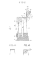
Fig. 3 illustrates a configuration of an essential portion of an extraction stage and of an extraction channel on the upstream side of a low-pressure turbine as viewed from the side. Incidentally, the same constituent elements as in the first embodiment are denoted with like reference numerals and their explanations are omitted. - Referring to
Fig. 3A , anextraction port 29 is provided between an outer circumferential sidestationary wall 27 supporting astator vane 26 and an outer circumferential sidestationary wall 28 constituting part of the next stage so as to circumferentially open and communicate with anextraction channel 30. Theextraction channel 30 communicates with an extraction chamber (not shown) circularly provided to circumferentially extend toward the outer circumferential side of the outer circumferentially side stationary wall. A portion ofsteam 20 flowing in thesteam passage 19 is extracted from theextraction port 29 through theextraction channel 30 to the extraction chamber to form an extractedsteam flow 40. Further, the extractedsteam flow 40 is taken out to the outside of the turbine through an extraction pipe circumferentially provided at a single or plurality of positions to connect with the extraction chamber. - A plurality of moving
blades 31 are secured to a turbine rotor 7 between thestator vanes 26 and theextraction port 29. The movingblades 31, along with thestator vanes 26, constitute an extraction stage. Ashroud 32 is mounted on the outer circumferential ends of the movingblades 31. An internalcircumferential surface 33 of theshroud 32 is radially smoothly bent to gradually increase a flare angle from the upstream toward the downstream. In addition, the internalcircumferential surface 33 is formed such that a moving blade outlet flare angle α3 is greater than a moving blade inlet flare angle α2. The moving blade outlet flare angle α3 is an angle formed between a tangential line F (indicated with a broken line) at a downstream side distal end of the shroud innercircumferential surface 33 and a turbinecentral axis 50. The moving blade inlet flare angle α2 is an angle formed between a tangential line E (indicated with a broken line) at an upstream side distal end of the shroud innercircumferential surface 33 and the turbinecentral axis 50. - An angle formed between an inner
circumferential surface 34 of the outer circumferential sidestator blade wall 27 and the turbinecentral axis 50 is defined as a moving blade upstream side flare angle α1. An angle formed between an upstream side lateral wall of theextraction port 29 and the turbinecentral axis 50 is defined as a moving blade downstream side flare angle α4. The innercircumferential surface 33 of theshroud 32 in the present embodiment is formed such that the moving blade inlet flare angle α2 is generally equal to the moving blade upstream side flare angle α1. In addition, the moving blade outlet flare angle α3 is generally equal to the moving blade downstream side flare angle α4. - An outer circumferential surface of the
shroud 32 is composed of an upstream sideparallel surface 37 being parallel to the turbinecentral axis 50 and including an upstream side end; a downstream sideparallel surface 38 being parallel to the turbinecentral axis 50 and including a downstream sideparallel surface 38; and acurved surface 39 radially bent relative to the turbinecentral axis 50 so as to connect the upstream sideparallel surface 37 with the downstream sideparallel surface 38. Also in the present embodiment, the shroud upstream side outer diameter is made smaller than the shroud downstream side outer diameter.
This intends to reduce the weight of the shroud. - The low-pressure turbine upstream stage may suffer from a significant influence on performance degradation caused by steam leakage. Therefore, seal fins 6 are arranged on the inner circumferential surface of the outer circumferential side
stationary wall 27 opposite the upstream sideparallel surface 37 and the downstream sideparallel surface 38 so as to be circumferentially extended. A step is provided on a seal fin installation portion of the outer circumferential side stationary wall in order to make a distance between the seal fins and the parallel surfaces constant. The positional relationship between the seal fins 6 and theshroud 32 is axially shifted due to thermal extension difference resulting from high temperature during the operation. However, even in such a case, since the seal fins are arranged on the parallel surfaces of the shroud outer circumferential surface, a gap between the seal fins 6 and theshroud 32 can be allowed to remain unchanged during operation to maintain sealing performance. - As shown in
Fig. 3A , a portion, on the outer circumferential side, of the steam flow leaving the movingblade 31 has a radial component and is introduced into theextraction channel 30. -
Fig. 4A is a schematic view illustrating an axially shortened extraction stage on the upstream side of a traditional low-pressure turbine. An upstream stage of the low-pressure turbine has a blade shorter than that of the downstream stage and a large seal gap relative to the blade length. Therefore, the upstream stage has a relatively more significant leakage loss than the downstream stage. Thus, it is necessary to enhance a seal effect by arranging a plurality offins 61 from the inlet to outlet of the movingblade 31. However, the low-pressure turbine has a large thermal extension difference. It is necessary, therefore, to arrange ashroud 41 in parallel to a turbinecentral axis 50 in order to maintain a radial gap. In other words, both a moving blade inlet flare angle and a moving blade outlet flare angle in theshroud 41 are 0 degree. The low-pressure turbine upstream stage has a blade smaller than, thus circumferential velocity lower than those of the downstream stage, which leads to a low flow velocity at a blade distal end. Further, the low-pressure turbine upstream stage has an accelerated flow with normal pressure gradient; therefore, separation is unlikely to occur. However, the extraction stage is provided with anextraction channel 30 adjacently to a downstream side steam path outer circumferential wall to allow a portion of steam to escape. If a shaft is reduced in length, a deviation between a moving blade outlet flare angle α3 and a moving blade downstream flare angle α4 is increased. In addition, a distance between the moving blade outlet and theextraction port 29 is reduced to shorten a shaft span. Therefore, steam is radially turned in a short shaft span between the moving blade outlet and theextraction port 29. Thus, aseparation swirl 42 may occur close to theextraction port 29 in some cases. - Returning to
Fig. 3A and 3B , in the present embodiment, the innercircumferential surface 33 of theshroud 32 is radially smoothly bent so as to gradually increase the flare angle from the upstream toward the downstream. In addition, the moving blade inlet flare angle α2 is generally equal to the moving blade upstream side flare angle α1 and the moving blade outlet flare angle α3 is generally equal to the moving blade downstream side flare angle α4. Therefore, the steam flow is radially turned between the inlet and outlet of the movingblade 2, which can radially turn the steam flow on the upstream side of theextraction port 29. Thus, the axial length of the turbine can be reduced while suppressing the lowering of turbine efficiency resulting from flow separation at the extraction channel inlet portion. - Incidentally, also in the present embodiment, it is preferred that the moving blade inlet flare angle α2 be equal to the moving blade upstream side flare angle α1 and the moving blade outlet flare angle α3 be equal to the moving blade downstream side flare angle α4. However, if respective deviations of the flare angles are generally equal to each other, i.e., if each of the deviations falls within 5°, achievement of the effect of the present invention can be expected.
- The shroud shown in
Figs. 4B and 4C is formed of a parallel surface parallel to the central axis from the upstream end to downstream end of the outer circumferential surface. In contrast to this, theshroud 32 of the present embodiment is formed such that the outer circumferential surface includes the upstream side parallel surface, the downstream side parallel surface, and the curved surface radially bent to connect the upstream side parallel surface with the downstream side parallel surface. In addition, the shroud downstream side outer diameter is made greater than the shroud upstream side outer diameter. Therefore, even if the curvature of theshroud 32 is increased, i.e., even if the difference between the moving blade inlet flare angle α2 and the moving blade outlet flare angle α3 is increased, it is possible to suppress an increase in the weight of the shroud per se. As a result, it is possible to prevent the lowering of the strength reliability of the turbine blade. - A description is given of a fourth embodiment of the present invention.
Figs. 5A and 5B are schematic views illustrating a configuration of an essential portion of an extraction stage and of an extraction channel on the upstream side of a low-pressure turbine as viewed from the side. Incidentally, the same constituent elements as in the third embodiment are denoted with like reference numerals and their explanations are omitted. - The present embodiment has a structure different from the third embodiment in a shroud. An inner circumferential surface of the shroud 43 of the present embodiment is composed of an upstream side inner
circumferential surface 45 including an upstream end and a downstream side innercircumferential surface 46 including a downstream end. Also in the present embodiment, the inner circumferential surface of the shroud 43 is formed as below. A moving blade inlet flare αngle α2 is generally equal to a moving blade upstream side flare α1. The moving blade inlet flare angle α2 is an angle formed between the upstream side innercircumferential surface 45 and the turbinecentral axis 50. The moving blade upstream side flare angle α1 is an angle formed between the innercircumferential surface 33 of the outer circumferential sidestationary wall 27 and the turbinecentral axis 50. In addition, a moving blade outlet flare angle α3 is generally equal to a moving blade downstream side flare angle α4. The moving blade outlet flare angle α3 is an angle formed between the downstream side innercircumferential surface 46 and the turbinecentral axis 50. The moving blade downstream side flare angle α4 is an angle formed between an inner circumferential surface 36 of an outer circumferential sidestationary wall 28 adjacently provided on the downstream side. Further, the moving blade outlet flare angle α3 is formed greater than the moving blade inlet flare angle α2. - In contrast, the outer
circumferential surface 47 of the shroud 43 is composed of a parallel surface parallel to the turbinecentral axis 50 from the upstream end to the downstream end. In addition, seal fins 6 are provided on the outer circumferential sidestationary wall 27 opposite the parallel surface. - The present embodiment provides the same effect as that of the third embodiment shown in
Figs. 3A and 3B . The shroud 43 of the present embodiment is formed with a hollow internal portion, which intends weight reduction. In this way, it is possible to suppress an increase in the weight of the shroud per se while keeping the shroud outercircumferential surface 47 and the outer circumferential side stationary wall parallel to each other. As a result, it is possible to prevent the lowering of strength reliability of the turbine blade while maintaining sealing performance. - A description is given of a fifth embodiment of the present invention.
Fig. 6A illustrates a configuration of an essential portion of an extraction stage and of an extraction channel on the downstream side of a low-pressure turbine as viewed from the side. An extraction portion is the same as that of the third embodiment. The present embodiment is different from the third embodiment in that a shroud and seal fins are configured to have the same shapes as those of the first embodiment. Also the present embodiment provides the same effect as that of the third embodiment. - Features, components and specific details of the structures of the above-described embodiments may be exchanged or combined to form further embodiments optimized for the respective application. As far as those modifications are apparent for an expert skilled in the art they shall be disclosed implicitly by the above description without specifying explicitly every possible combination.
Claims (8)
- A moving blade for a steam turbine, the moving blade having a shroud formed at an external circumferential side distal end,
wherein the shroud has an inner circumferential surface so formed that:a moving blade outlet flare angle is greater than a moving blade inlet flare angle;the moving blade inlet flare angle is generally equal to a moving blade upstream side flare angle of an outer circumferential side stationary wall adjacently provided on an upstream side of the shroud; andthe moving blade outlet flare angle is generally equal to a moving blade downstream side flare angle of the outer circumferential side stationary wall adjacently provided on a downstream side of the shroud. - The moving blade according to claim 1,
wherein an outer circumferential surface of the shroud has a surface including a downstream side distal end and being parallel to a turbine central axis, and
a distance between an upstream side distal end of the outer circumferential surface and the turbine central axis is smaller than a distance between the downstream side distal end of the outer circumferential surface and the turbine central axis. - The moving blade according to claim 1 or 2,
wherein an outer circumferential surface of the shroud is formed of a surface generally parallel to a turbine central axis, and
the shroud is hollow. - The moving blade according to at least one of claims 1 to 3,
wherein the moving blade constitutes a final stage of a low-pressure turbine. - The moving blade according to at least one of claims 1 to 4,
wherein the moving blade forms an extraction stage adjacently provided on an upstream side of an extraction channel adapted to extract steam from a steam passage. - A steam turbine comprising:a turbine rotor;a moving blade secured to the turbine rotor;a shroud provided on an outer circumferential side distal end of the moving blade; andan outer circumferential side stationary wall internally embracing the turbine rotor, the stationary wall forming an outer circumferential side passage wall of a steam path;wherein the shroud has an inner circumferential surface so formed that:a moving blade outlet flare angle is greater than a moving blade inlet flare angle;the moving blade inlet flare angle is generally equal to a moving blade upstream side flare angle of an outer circumferential side stationary wall adjacently provided on an upstream side of the moving blade; andthe moving blade outlet flare angle is generally equal to a moving blade downstream side flare angle of the outer circumferential side stationary wall adjacently provided on a downstream side of the moving blade.
- The steam turbine according to claim 6,
wherein an outer circumferential surface of the shroud has a surface including a downstream side distal end and being parallel to a turbine central axis, and
a distance between an upstream side distal end of the outer circumferential surface and the turbine central axis is smaller than a distance between the downstream side distal end of the outer circumferential surface and the turbine central axis. - The steam turbine according to claim 6 or 7,
wherein an outer circumferential surface of the shroud is formed of a surface generally parallel to a turbine central axis, and
the shroud is hollow.
Applications Claiming Priority (1)
| Application Number | Priority Date | Filing Date | Title |
|---|---|---|---|
| JP2009062229A JP2010216321A (en) | 2009-03-16 | 2009-03-16 | Moving blade of steam turbine, and steam turbine using the same |
Publications (2)
| Publication Number | Publication Date |
|---|---|
| EP2236754A2 true EP2236754A2 (en) | 2010-10-06 |
| EP2236754A3 EP2236754A3 (en) | 2014-01-08 |
Family
ID=41849497
Family Applications (1)
| Application Number | Title | Priority Date | Filing Date |
|---|---|---|---|
| EP10153973.2A Withdrawn EP2236754A3 (en) | 2009-03-16 | 2010-02-18 | Steam turbine rotor blade and corresponding steam turbine |
Country Status (4)
| Country | Link |
|---|---|
| US (1) | US20100232966A1 (en) |
| EP (1) | EP2236754A3 (en) |
| JP (1) | JP2010216321A (en) |
| CN (1) | CN101839148A (en) |
Cited By (3)
| Publication number | Priority date | Publication date | Assignee | Title |
|---|---|---|---|---|
| WO2011045346A1 (en) * | 2009-10-15 | 2011-04-21 | Abb Turbo Systems Ag | Turbine wheel |
| EP2853694A3 (en) * | 2013-08-28 | 2015-04-22 | Kabushiki Kaisha Toshiba | Steam turbine |
| EP2692996A3 (en) * | 2012-08-02 | 2015-12-23 | Kabushiki Kaisha Toshiba | Sealing structure in steam turbine |
Families Citing this family (19)
| Publication number | Priority date | Publication date | Assignee | Title |
|---|---|---|---|---|
| JP2011080452A (en) | 2009-10-09 | 2011-04-21 | Mitsubishi Heavy Ind Ltd | Turbine |
| JP5484990B2 (en) | 2010-03-30 | 2014-05-07 | 三菱重工業株式会社 | Turbine |
| US8708639B2 (en) * | 2010-10-11 | 2014-04-29 | The Coca-Cola Company | Turbine bucket shroud tail |
| US9249687B2 (en) * | 2010-10-27 | 2016-02-02 | General Electric Company | Turbine exhaust diffusion system and method |
| JP5517910B2 (en) * | 2010-12-22 | 2014-06-11 | 三菱重工業株式会社 | Turbine and seal structure |
| CN102108881B (en) * | 2011-03-22 | 2013-11-27 | 东方电气集团东方汽轮机有限公司 | Secondary final stage blade for half-RPM (Revolution per Minute) nuclear turbine |
| CN102108882B (en) * | 2011-03-22 | 2013-11-27 | 东方电气集团东方汽轮机有限公司 | Last stage blade for half speed nuclear power steam turbine |
| US20130243564A1 (en) * | 2012-03-14 | 2013-09-19 | Prakash Bavanjibhai Dalsania | Exhaust diffuser for turbine |
| JP6125351B2 (en) * | 2013-06-27 | 2017-05-10 | 株式会社東芝 | Steam turbine |
| KR101811223B1 (en) * | 2013-08-28 | 2017-12-21 | 가부시끼가이샤 도시바 | Steam turbine |
| JP2015194085A (en) * | 2014-03-31 | 2015-11-05 | 株式会社東芝 | steam turbine |
| CN105401982B (en) * | 2015-12-14 | 2017-11-07 | 东方电气集团东方汽轮机有限公司 | Half speed nuclear steam turbine final stage moving blade blade structure |
| JP2018003812A (en) * | 2016-07-08 | 2018-01-11 | 三菱日立パワーシステムズ株式会社 | Bucket and turbine using the same |
| CN106050320B (en) * | 2016-07-13 | 2018-05-22 | 东方电气集团东方汽轮机有限公司 | The final stage moving blade of the feed pump turbine of 1000MW grade air-cooled steam turbine generator groups |
| CN108223025A (en) * | 2016-12-14 | 2018-06-29 | 中国石油天然气集团公司 | A kind of flue gas turbine expander transition grommet and flue gas turbine expander |
| JP7051618B2 (en) * | 2018-07-02 | 2022-04-11 | 三菱重工業株式会社 | Static wing segment and steam turbine |
| DE112019003577T5 (en) * | 2018-07-13 | 2021-06-24 | Mitsubishi Power, Ltd. | Flow guide, steam turbine, inner element and method for producing flow guide |
| JP7254472B2 (en) * | 2018-09-28 | 2023-04-10 | 三菱重工業株式会社 | Steam turbine exhaust chamber, steam turbine, and method for replacing steam turbine |
| JP7368260B2 (en) * | 2020-01-31 | 2023-10-24 | 三菱重工業株式会社 | turbine |
Citations (1)
| Publication number | Priority date | Publication date | Assignee | Title |
|---|---|---|---|---|
| JP2003027901A (en) | 2001-07-13 | 2003-01-29 | Mitsubishi Heavy Ind Ltd | Axial flow turbine |
Family Cites Families (15)
| Publication number | Priority date | Publication date | Assignee | Title |
|---|---|---|---|---|
| JPS529701A (en) * | 1975-07-11 | 1977-01-25 | Hitachi Ltd | Rotor blade connecting mechanism for axial flow fluid machine |
| US4053254A (en) * | 1976-03-26 | 1977-10-11 | United Technologies Corporation | Turbine case cooling system |
| FR2361531A1 (en) * | 1976-08-13 | 1978-03-10 | Europ Turb Vapeur | COMPRESSIBLE FLUID TURBINE |
| US4213296A (en) * | 1977-12-21 | 1980-07-22 | United Technologies Corporation | Seal clearance control system for a gas turbine |
| FR2452601A1 (en) * | 1979-03-30 | 1980-10-24 | Snecma | REMOVABLE SEALING COVER FOR TURBOJET BLOWER HOUSING |
| JPS5773805A (en) * | 1980-10-24 | 1982-05-08 | Toshiba Corp | Axial frow hydraulic equipment |
| FR2635562B1 (en) * | 1988-08-18 | 1993-12-24 | Snecma | TURBINE STATOR RING ASSOCIATED WITH A TURBINE HOUSING BINDING SUPPORT |
| JPH08210101A (en) * | 1995-02-02 | 1996-08-20 | Mitsubishi Heavy Ind Ltd | Turbine moving blade |
| JPH10331604A (en) * | 1997-05-30 | 1998-12-15 | Toshiba Corp | Steam turbine plant |
| EP0903468B1 (en) * | 1997-09-19 | 2003-08-20 | ALSTOM (Switzerland) Ltd | Gap sealing device |
| US6471480B1 (en) * | 2001-04-16 | 2002-10-29 | United Technologies Corporation | Thin walled cooled hollow tip shroud |
| JP2003106107A (en) * | 2001-09-27 | 2003-04-09 | Mitsubishi Heavy Ind Ltd | Turbine |
| US7547187B2 (en) * | 2005-03-31 | 2009-06-16 | Hitachi, Ltd. | Axial turbine |
| JP4515404B2 (en) * | 2005-03-31 | 2010-07-28 | 株式会社日立製作所 | Axial flow turbine |
| JP4869974B2 (en) * | 2005-03-31 | 2012-02-08 | 株式会社日立製作所 | Axial flow turbine |
-
2009
- 2009-03-16 JP JP2009062229A patent/JP2010216321A/en active Pending
-
2010
- 2010-02-11 CN CN201010115612A patent/CN101839148A/en active Pending
- 2010-02-17 US US12/706,866 patent/US20100232966A1/en not_active Abandoned
- 2010-02-18 EP EP10153973.2A patent/EP2236754A3/en not_active Withdrawn
Patent Citations (1)
| Publication number | Priority date | Publication date | Assignee | Title |
|---|---|---|---|---|
| JP2003027901A (en) | 2001-07-13 | 2003-01-29 | Mitsubishi Heavy Ind Ltd | Axial flow turbine |
Cited By (5)
| Publication number | Priority date | Publication date | Assignee | Title |
|---|---|---|---|---|
| WO2011045346A1 (en) * | 2009-10-15 | 2011-04-21 | Abb Turbo Systems Ag | Turbine wheel |
| EP2692996A3 (en) * | 2012-08-02 | 2015-12-23 | Kabushiki Kaisha Toshiba | Sealing structure in steam turbine |
| US9732627B2 (en) | 2012-08-02 | 2017-08-15 | Kabushiki Kaisha Toshiba | Sealing structure in steam turbine |
| EP2853694A3 (en) * | 2013-08-28 | 2015-04-22 | Kabushiki Kaisha Toshiba | Steam turbine |
| US9581026B2 (en) | 2013-08-28 | 2017-02-28 | Kabushiki Kaisha Toshiba | Steam turbine |
Also Published As
| Publication number | Publication date |
|---|---|
| EP2236754A3 (en) | 2014-01-08 |
| US20100232966A1 (en) | 2010-09-16 |
| JP2010216321A (en) | 2010-09-30 |
| CN101839148A (en) | 2010-09-22 |
Similar Documents
| Publication | Publication Date | Title |
|---|---|---|
| EP2236754A2 (en) | Steam turbine rotor blade and corresponding steam turbine | |
| RU2519009C2 (en) | Air bleeder with inertial filter in compressor tandem rotor | |
| EP2617961B1 (en) | Radial turbine | |
| JP2010156335A (en) | Method and device concerning contour of improved turbine blade platform | |
| CN110094346B (en) | Passage between rotor platform and shroud in turbine engine | |
| US20120121394A1 (en) | Turbine and turbine rotor blade | |
| WO2018181343A1 (en) | Centrifugal compressor | |
| CN111094704B (en) | Diffuser for an exhaust gas turbine | |
| US8870532B2 (en) | Exhaust hood diffuser | |
| EP3325775A1 (en) | Turbine blade with contoured tip shroud | |
| US20150300190A1 (en) | Rotating machine | |
| CN110582649B (en) | Reinforced axial diffuser | |
| US8322972B2 (en) | Steampath flow separation reduction system | |
| JP6745233B2 (en) | Turbine and gas turbine | |
| EP2657481B1 (en) | Scroll portion structure for radial turbine or diagonal flow turbine | |
| JP2011117417A (en) | Exhaust gas inlet casing for exhaust turbocharger | |
| US8562289B2 (en) | Method and system for a leakage controlled fan housing | |
| US10519793B2 (en) | Brush seal for a turbine engine rotor | |
| EP3358134B1 (en) | Steam turbine with rotor blade | |
| US20130022444A1 (en) | Low pressure turbine exhaust diffuser with turbulators | |
| KR20140049490A (en) | Gas inlet housing | |
| US11879389B2 (en) | Concentric introduction of the waste-gate mass flow into a flow-optimized axial diffusor | |
| WO2022123839A1 (en) | Centrifugal compressor and supercharger | |
| US20230374907A1 (en) | Turbine | |
| US20220268161A1 (en) | Axial flow turbine |
Legal Events
| Date | Code | Title | Description |
|---|---|---|---|
| PUAI | Public reference made under article 153(3) epc to a published international application that has entered the european phase |
Free format text: ORIGINAL CODE: 0009012 |
|
| 17P | Request for examination filed |
Effective date: 20100528 |
|
| AK | Designated contracting states |
Kind code of ref document: A2 Designated state(s): AT BE BG CH CY CZ DE DK EE ES FI FR GB GR HR HU IE IS IT LI LT LU LV MC MK MT NL NO PL PT RO SE SI SK SM TR |
|
| AX | Request for extension of the european patent |
Extension state: AL BA RS |
|
| PUAL | Search report despatched |
Free format text: ORIGINAL CODE: 0009013 |
|
| AK | Designated contracting states |
Kind code of ref document: A3 Designated state(s): AT BE BG CH CY CZ DE DK EE ES FI FR GB GR HR HU IE IS IT LI LT LU LV MC MK MT NL NO PL PT RO SE SI SK SM TR |
|
| AX | Request for extension of the european patent |
Extension state: AL BA RS |
|
| RIC1 | Information provided on ipc code assigned before grant |
Ipc: F01D 5/22 20060101AFI20131203BHEP Ipc: F01D 5/14 20060101ALI20131203BHEP |
|
| STAA | Information on the status of an ep patent application or granted ep patent |
Free format text: STATUS: THE APPLICATION HAS BEEN WITHDRAWN |
|
| 18W | Application withdrawn |
Effective date: 20131213 |