JP7368260B2 - turbine - Google Patents
turbine Download PDFInfo
- Publication number
- JP7368260B2 JP7368260B2 JP2020015615A JP2020015615A JP7368260B2 JP 7368260 B2 JP7368260 B2 JP 7368260B2 JP 2020015615 A JP2020015615 A JP 2020015615A JP 2020015615 A JP2020015615 A JP 2020015615A JP 7368260 B2 JP7368260 B2 JP 7368260B2
- Authority
- JP
- Japan
- Prior art keywords
- main body
- vehicle interior
- member main
- rotor blade
- discharge port
- Prior art date
- Legal status (The legal status is an assumption and is not a legal conclusion. Google has not performed a legal analysis and makes no representation as to the accuracy of the status listed.)
- Active
Links
Images


Classifications
-
- F—MECHANICAL ENGINEERING; LIGHTING; HEATING; WEAPONS; BLASTING
- F01—MACHINES OR ENGINES IN GENERAL; ENGINE PLANTS IN GENERAL; STEAM ENGINES
- F01D—NON-POSITIVE DISPLACEMENT MACHINES OR ENGINES, e.g. STEAM TURBINES
- F01D25/00—Component parts, details, or accessories, not provided for in, or of interest apart from, other groups
- F01D25/30—Exhaust heads, chambers, or the like
-
- F—MECHANICAL ENGINEERING; LIGHTING; HEATING; WEAPONS; BLASTING
- F01—MACHINES OR ENGINES IN GENERAL; ENGINE PLANTS IN GENERAL; STEAM ENGINES
- F01D—NON-POSITIVE DISPLACEMENT MACHINES OR ENGINES, e.g. STEAM TURBINES
- F01D11/00—Preventing or minimising internal leakage of working-fluid, e.g. between stages
- F01D11/08—Preventing or minimising internal leakage of working-fluid, e.g. between stages for sealing space between rotor blade tips and stator
-
- F—MECHANICAL ENGINEERING; LIGHTING; HEATING; WEAPONS; BLASTING
- F01—MACHINES OR ENGINES IN GENERAL; ENGINE PLANTS IN GENERAL; STEAM ENGINES
- F01D—NON-POSITIVE DISPLACEMENT MACHINES OR ENGINES, e.g. STEAM TURBINES
- F01D25/00—Component parts, details, or accessories, not provided for in, or of interest apart from, other groups
- F01D25/24—Casings; Casing parts, e.g. diaphragms, casing fastenings
-
- F—MECHANICAL ENGINEERING; LIGHTING; HEATING; WEAPONS; BLASTING
- F01—MACHINES OR ENGINES IN GENERAL; ENGINE PLANTS IN GENERAL; STEAM ENGINES
- F01D—NON-POSITIVE DISPLACEMENT MACHINES OR ENGINES, e.g. STEAM TURBINES
- F01D9/00—Stators
- F01D9/02—Nozzles; Nozzle boxes; Stator blades; Guide conduits, e.g. individual nozzles
-
- F—MECHANICAL ENGINEERING; LIGHTING; HEATING; WEAPONS; BLASTING
- F05—INDEXING SCHEMES RELATING TO ENGINES OR PUMPS IN VARIOUS SUBCLASSES OF CLASSES F01-F04
- F05D—INDEXING SCHEME FOR ASPECTS RELATING TO NON-POSITIVE-DISPLACEMENT MACHINES OR ENGINES, GAS-TURBINES OR JET-PROPULSION PLANTS
- F05D2220/00—Application
- F05D2220/30—Application in turbines
- F05D2220/31—Application in turbines in steam turbines
-
- F—MECHANICAL ENGINEERING; LIGHTING; HEATING; WEAPONS; BLASTING
- F05—INDEXING SCHEMES RELATING TO ENGINES OR PUMPS IN VARIOUS SUBCLASSES OF CLASSES F01-F04
- F05D—INDEXING SCHEME FOR ASPECTS RELATING TO NON-POSITIVE-DISPLACEMENT MACHINES OR ENGINES, GAS-TURBINES OR JET-PROPULSION PLANTS
- F05D2220/00—Application
- F05D2220/30—Application in turbines
- F05D2220/32—Application in turbines in gas turbines
- F05D2220/321—Application in turbines in gas turbines for a special turbine stage
- F05D2220/3215—Application in turbines in gas turbines for a special turbine stage the last stage of the turbine
-
- F—MECHANICAL ENGINEERING; LIGHTING; HEATING; WEAPONS; BLASTING
- F05—INDEXING SCHEMES RELATING TO ENGINES OR PUMPS IN VARIOUS SUBCLASSES OF CLASSES F01-F04
- F05D—INDEXING SCHEME FOR ASPECTS RELATING TO NON-POSITIVE-DISPLACEMENT MACHINES OR ENGINES, GAS-TURBINES OR JET-PROPULSION PLANTS
- F05D2240/00—Components
- F05D2240/10—Stators
- F05D2240/12—Fluid guiding means, e.g. vanes
- F05D2240/126—Baffles or ribs
-
- F—MECHANICAL ENGINEERING; LIGHTING; HEATING; WEAPONS; BLASTING
- F05—INDEXING SCHEMES RELATING TO ENGINES OR PUMPS IN VARIOUS SUBCLASSES OF CLASSES F01-F04
- F05D—INDEXING SCHEME FOR ASPECTS RELATING TO NON-POSITIVE-DISPLACEMENT MACHINES OR ENGINES, GAS-TURBINES OR JET-PROPULSION PLANTS
- F05D2240/00—Components
- F05D2240/10—Stators
- F05D2240/12—Fluid guiding means, e.g. vanes
- F05D2240/129—Cascades, i.e. assemblies of similar profiles acting in parallel
-
- F—MECHANICAL ENGINEERING; LIGHTING; HEATING; WEAPONS; BLASTING
- F05—INDEXING SCHEMES RELATING TO ENGINES OR PUMPS IN VARIOUS SUBCLASSES OF CLASSES F01-F04
- F05D—INDEXING SCHEME FOR ASPECTS RELATING TO NON-POSITIVE-DISPLACEMENT MACHINES OR ENGINES, GAS-TURBINES OR JET-PROPULSION PLANTS
- F05D2250/00—Geometry
- F05D2250/20—Three-dimensional
- F05D2250/27—Three-dimensional hyperboloid
-
- F—MECHANICAL ENGINEERING; LIGHTING; HEATING; WEAPONS; BLASTING
- F05—INDEXING SCHEMES RELATING TO ENGINES OR PUMPS IN VARIOUS SUBCLASSES OF CLASSES F01-F04
- F05D—INDEXING SCHEME FOR ASPECTS RELATING TO NON-POSITIVE-DISPLACEMENT MACHINES OR ENGINES, GAS-TURBINES OR JET-PROPULSION PLANTS
- F05D2250/00—Geometry
- F05D2250/30—Arrangement of components
- F05D2250/32—Arrangement of components according to their shape
- F05D2250/324—Arrangement of components according to their shape divergent
-
- F—MECHANICAL ENGINEERING; LIGHTING; HEATING; WEAPONS; BLASTING
- F05—INDEXING SCHEMES RELATING TO ENGINES OR PUMPS IN VARIOUS SUBCLASSES OF CLASSES F01-F04
- F05D—INDEXING SCHEME FOR ASPECTS RELATING TO NON-POSITIVE-DISPLACEMENT MACHINES OR ENGINES, GAS-TURBINES OR JET-PROPULSION PLANTS
- F05D2270/00—Control
- F05D2270/01—Purpose of the control system
- F05D2270/17—Purpose of the control system to control boundary layer
Landscapes
- Engineering & Computer Science (AREA)
- Mechanical Engineering (AREA)
- General Engineering & Computer Science (AREA)
- Turbine Rotor Nozzle Sealing (AREA)
Description
本開示は、タービンに関する。 TECHNICAL FIELD This disclosure relates to turbines.
蒸気タービンやガスタービンを含むタービンは、軸線回りに回転する回転軸、及び該回転軸の外周面に設けられた動翼列を有するロータと、このロータを外周側から覆う筒状の車室と、車室の内周面に設けられた静翼列と、を備えている。例えば蒸気タービンでは、車室内に高圧の蒸気が供給されることで、動翼を通じてロータに回転力が与えられる。ガスタービンでは、燃焼器から供給された高温高圧の燃焼ガスによって、ロータに回転力が与えられる。 A turbine, including a steam turbine or a gas turbine, includes a rotary shaft that rotates around the axis, a rotor having a row of rotor blades provided on the outer peripheral surface of the rotary shaft, and a cylindrical casing that covers the rotor from the outer peripheral side. , and a stator blade row provided on the inner circumferential surface of the vehicle compartment. For example, in a steam turbine, high-pressure steam is supplied into the cabin, and rotational force is applied to the rotor through the rotor blades. In a gas turbine, rotational force is applied to a rotor by high-temperature, high-pressure combustion gas supplied from a combustor.
特許文献1に記載されているように、車室内では、下流側に向かうに従って流体の圧力が下がるため、当該車室の内周面は、下流側に向かうに従って径方向外側に拡径していることが一般的である。
As described in
ここで、下流側に向かうに従って車室の内周面を径方向に過剰に拡大させてしまうと、流体の流れが当該内周面の拡大に追従しきれず、剥離を生じてしまう。このような剥離は損失につながり、タービンの性能に影響が及ぶ虞がある。タービンの出力向上には車室内周面の径方向への拡大が望ましいが、剥離による性能低下を回避する必要から、従来の車室の内周面の径方向への拡大は制約を受けていた。 Here, if the inner circumferential surface of the vehicle compartment is expanded excessively in the radial direction toward the downstream side, the fluid flow cannot follow the expansion of the inner circumferential surface, resulting in separation. Such spalling can lead to losses and affect turbine performance. In order to increase the output of the turbine, it is desirable to expand the radial direction of the inner circumferential surface of the casing, but conventional expansion of the inner circumferential surface of the casing in the radial direction has been restricted due to the need to avoid performance deterioration due to peeling. .
本開示は上記課題を解決するためになされたものであって、下流側に向かうに従って内周面が径方向に大きく拡大することによる剥離を抑制して、剥離に起因する損失を低減し、さらに性能の向上したタービンを提供することを目的とする。 The present disclosure has been made to solve the above-mentioned problems, and suppresses peeling caused by the inner circumferential surface greatly expanding in the radial direction toward the downstream side, reduces loss due to peeling, and further The purpose is to provide a turbine with improved performance.
上記課題を解決するために、本開示に係るタービンは、軸線回りに回転可能な回転軸、及び該回転軸の外周面に前記軸線方向に間隔を開けて設けられた複数の動翼列を有するロータと、該ロータを外周側から覆うとともに前記軸線方向の下流側に向かうにしたがって径方向外側に延びる車室内周面を有する車室と、前記車室内周面を内周側から覆うことで、上流側で前記車室内周面との間に抽気口を形成し、下流側に吐出口を形成する内周部材本体と、を備え、前記内周部材本体は、前記複数の動翼列のうちで最も前記下流側の最終段動翼列の少なくとも一部と、前記軸線に対する径方向で対向し、前記抽気口は、前記最終段動翼列の前記下流側の端よりも前記上流側に位置し、前記吐出口は、前記最終段動翼列よりも下流側に位置し、前記抽気口、及び前記吐出口は、前記軸線を中心とする環状をなし、前記吐出口の流路断面積は、前記抽気口の流路断面積よりも小さく設定されている。 In order to solve the above problems, a turbine according to the present disclosure includes a rotating shaft rotatable around the axis, and a plurality of rotor blade rows provided at intervals in the axial direction on the outer peripheral surface of the rotating shaft. A rotor, a vehicle interior having a vehicle interior circumferential surface that covers the rotor from the outer circumferential side and extends radially outward toward the downstream side in the axial direction, and covers the vehicle interior circumferential surface from the inner circumferential side, an inner circumferential member main body forming an air bleed port between the vehicle interior peripheral surface on the upstream side and a discharge port on the downstream side, the inner circumferential member main body forming one of the plurality of rotor blade rows. radially opposite to at least a part of the final stage rotor blade row on the most downstream side, and the bleed port is located on the upstream side of the downstream end of the final stage rotor blade row. The discharge port is located downstream of the final stage rotor blade row, the bleed port and the discharge port have an annular shape centered on the axis, and the flow path cross-sectional area of the discharge port is , is set smaller than the flow path cross-sectional area of the air bleed port.
本開示によれば、損失が低減されることで、さらに性能の向上したタービンを提供することができる。 According to the present disclosure, a turbine with further improved performance can be provided by reducing loss.
<第一実施形態>
(蒸気タービンの構成)
以下、本開示の第一実施形態に係るタービンの一例として、蒸気タービン100について、図1と図2を参照して説明する。蒸気タービン100は、ロータ1と、車室2と、内周部材40(図2参照)と、を備えている。
<First embodiment>
(Steam turbine configuration)
Hereinafter, a
ロータ1は、軸線Oに沿って延びる柱状の回転軸11と、この回転軸11の外周面に設けられた複数の動翼列12と、を有している。回転軸11は、軸線O回りに回転可能とされている。動翼列12は、回転軸11の外周面上で、軸線Oに対する周方向に配列された複数の動翼を有している。回転軸11には、この動翼列12が軸線O方向に間隔をあけて複数配列されている。
The
車室2は、内車室21と、排気ケーシング22と、を有している。内車室21は、上記のロータ1を外周側から覆うことで、ロータ1の外周面との間に主流路Pmを形成している。内車室21は、軸線Oを中心とする筒状の内車室本体21Hと、内車室本体21Hの内周側に固定されている複数の静翼保持リング21Rと、静翼保持リング21Rのさらに内周側に設けられている静翼列23と、を有している。
The
静翼保持リング21Rは、軸線O方向における複数の動翼列12それぞれの一方側、すなわち流体の流れ方向では上流側に1つずつ設けられている。それぞれの静翼保持リング21Rは、軸線Oを中心とする環状をなしている。静翼保持リング21Rの内周面21S(車室内周面)は、軸線O方向一方側から他方側に向かうに従って径方向外側に向かって延びている。静翼列23は、この静翼保持リング21Rの内周面21Sから径方向内側に向かって延びる複数の静翼を有している。つまり、上記の主流路Pm内では、軸線O方向一方側から他方側にかけて、静翼列23と動翼列12とが交互に配列されている。
One stator
内車室21の軸線O方向一方側の端部には、外部の蒸気供給源から導かれた高温高圧の蒸気が流入する供給管2Eが設けられている。供給管2Eの延長上には、不図示の開閉弁や調整弁が取り付けられている。この供給管2Eから内車室21の内部に導かれた蒸気は、主流路Pmを流通する中途で、上記の静翼列23、及び動翼列12に交互に衝突する。なお、以降の説明では、軸線O方向における蒸気が流れて来る側を上流側と呼び、蒸気が流れ去る側を下流側と呼ぶことがある。また、複数の動翼列12のうち、最も下流側に配置されている動翼列12を最終段動翼列12Dと呼ぶことがある。なお、この最終段動翼列12Dを含めて、全ての動翼列12の先端にはシュラウド12Sが設けられている。
A
内車室21の下流側には、排気ケーシング22が接続されている。排気ケーシング22は、主流路Pmから排出された蒸気を外部の機器(復水器等)に向けて導くための流路(排気流路Pe)を形成している。具体的には、排気ケーシング22は、ベアリングコーン22Aと、このベアリングコーン22Aを外周側から覆う外車室22Bと、フローガイド50と、を有している。ベアリングコーン22Aは、上流側から下流側に向かうに従って径方向外側に向かって延びる円錐形状をなしている。外車室22Bは、ベアリングコーン22Aを下流側及び径方向外側から覆う有底筒状をなしている。排気流路Peに流れ込んだ蒸気は、ベアリングコーン22Aに沿って下流側に向かって流れた後、径方向外側に向かう方向に転向し、さらに外車室22Bの内面に沿って上流側に流れる。
An
(フローガイドの構成)
フローガイド50は、上述のような蒸気の流れを排気流路Pe中で円滑に案内するために設けられている。フローガイド50は、内車室本体21Hの下流側の端縁からさらに下流側に向かって延びる筒状をなしている。より詳細には、このフローガイド50は、下流側に向かうに従って次第に拡径する漏斗状をなしている。なお、フローガイド50の内周面50Sは、上述の静翼保持リング21Rの内周面に連続することで、ともに上述の内周面21S(車室内周面)の一部を形成している。
(Flow guide configuration)
The
ここで、上記のように、最終段動翼列12Dに対応する静翼保持リング21Rの内周面21S(車室内周面)から、フローガイド50の内周面50Sにかけての領域は急激に拡径している。この拡径が過剰になると、流体の流れが当該内周面21Sに追従しきれず、流れの剥離を生じることになる。このような剥離が発生すると損失となり、蒸気タービン100の性能に影響が及んでしまう。
Here, as described above, the area from the inner
そこで、本実施形態では、図2に示すように、最終段動翼列12Dに対応する静翼保持リング21Rの内周面21SにキャビティCが形成されているとともに、このキャビティCを覆う内周部材40が設けられている。
Therefore, in this embodiment, as shown in FIG. A
(内周部材の構成)
キャビティCは、内周面21Sにおける最終段動翼列12Dに対向する部分に形成された凹部である。キャビティCは、内周面21Sから径方向外側に向かって凹むとともに、軸線Oを中心とする環状をなしている。キャビティC内における径方向外側の面はキャビティ内周面C1とされ、上流側の面はキャビティ上流面C2とされている。キャビティ内周面C1は、一例として軸線Oを中心とする円筒面状である。なお、キャビティ内周面C1は、径方向の寸法が軸線O方向にかけて変化している形状を採ることも可能である。キャビティ上流面C2は、軸線Oに対する径方向に広がっている。
(Configuration of inner peripheral member)
The cavity C is a recess formed in a portion of the inner
内周部材40は、支持部30と、内周部材本体40Hと、を有している。支持部30は、キャビティ内周面C1から径方向内側に向かって延びている。キャビティ内周面C1上には、周方向に間隔をあけて複数の支持部30が配列されている。支持部30の径方向内側の端部は、内周部材本体40Hの外周面(後述する流路形成面40T)に接続されている。
The inner
内周部材本体40Hは、軸線Oを中心とする筒状をなしている。内周部材本体40Hの外周面は流路形成面40Tとされている。流路形成面40Tは、キャビティ内周面C1に対して径方向に間隔をあけて対向している。流路形成面40Tは、下流側に向かうに従って次第に径方向外側に向かって湾曲している。内周部材本体40Hの内周面は案内面40Sとされている。案内面40Sは上述の主流路Pmに臨んでいる。案内面40Sは、流路形成面40Tと同様に、下流側に向かうに従って次第に径方向外側に向かって湾曲している。
The inner peripheral member
内周部材本体40Hの上流側の端縁P1は、キャビティ上流面C2に対して軸線O方向に隙間をあけて対向している。この隙間は、キャビティC内と主流路Pmとを連通させる抽気口E1とされている。つまり、この抽気口E1を通じて主流路Pm内の蒸気の一部がキャビティC内に流入する。一方で、内周部材本体40Hの下流側の端縁P2は、キャビティCの下流側に接続されているフローガイド50の内周面50S(21S)に対して隙間をあけて対向している。この隙間は吐出口E2とされている。キャビティC内に流入した蒸気は、この吐出口E2から下流側に向かってジェット噴流Fjとして吹き出される。
The upstream edge P1 of the inner
ここで、吐出口E2の流路断面積は、抽気口E1の流路断面積よりも小さく設定されている。つまり、内周部材本体40Hの下流側の端縁P2とフローガイド50の内周面との間の離間距離は、上流側の端縁P1とキャビティ上流面C2との間の離間距離よりも小さく設定されている。また、内周部材本体40Hの下流側の端縁P2は、軸線O方向において、フローガイド50の始点Pc(つまり、フローガイド50の上流側の端縁)よりもさらに下流側に位置している。さらに、軸線Oを含む断面視で、内周部材本体40Hの吐出口E2側の端縁P2における接線Lcは、下流側に向かうに従って次第に軸線Oから離間する方向に延びている。これにより、上述のジェット噴流Fjは、下流側に向かうに従って径方向外側に広がるように吹き出される。
Here, the flow path cross-sectional area of the discharge port E2 is set smaller than the flow path cross-sectional area of the bleed port E1. In other words, the distance between the downstream edge P2 of the inner peripheral member
(作用効果)
次に、本実施形態に係る蒸気タービン100の動作について説明する。蒸気タービン100を運転するに当たっては、まず外部の蒸気供給源(ボイラ等)で生成された高温高圧の蒸気を、供給管2Eを通じて車室2の内部(主流路Pm)に導く。主流路Pmを下流側に向かって流通する中途で、この蒸気は静翼列23によって案内されつつ動翼列12に衝突する。これにより、ロータ1は軸線O回りに回転する。ロータ1の回転エネルギーは軸端から取り出されて、発電機等の外部機器の駆動に用いられる。主流路Pmを通過した蒸気は、上述の排気流路Peを通じて他の機器(一例として復水器)に送られる。
(effect)
Next, the operation of the
ここで、最終段動翼列12Dに対応する静翼保持リング21Rの内周面21S(車室内周面)の下流端から始まる、フローガイド50の内周面は圧力回復のため急激に拡径する。この拡径が過剰になると、流体の流れが当該内周面に追従しきれず、流れの剥離を生じることがある。このような剥離は損失につながり、蒸気タービン100の性能に影響が及ぶ虞がある。
Here, the inner circumferential surface of the
しかしながら、図2に示すように、本実施形態では、車室2内部を流れる蒸気の一部は、主流Fmから分岐して分岐流Fdとして抽気口E1を通じてキャビティC内に流れ込む。吐出口E2の流路断面積は、キャビティC内に流れ込んだ蒸気は、吐出口E2から下流側に向かってジェット噴流Fjとして吹き出される。これにより、内周部材本体40Hの内周面(案内面40S)に沿う流れ(拡径流Fg)は、コアンダ効果によって当該吐出口E2から吹き出したジェット噴流Fjに引き付けられる。したがって、内周部材本体40Hの下流側で、蒸気の内周面21Sからの剥離を抑制することができる。また、上記構成では、抽気口E1、及び吐出口E2が軸線Oを中心とする環状をなしていることから、車室2内部における全周にわたって上記のような剥離の発生を抑制することができる。さらに、上記構成によれば、吐出口E2の流路断面積は、抽気口E1の流路断面積よりも小さく設定されている。これにより、キャビティ内の圧力は最終段動翼列12Dの上流側の主流の圧力とほぼ等しくなり、最終段動翼列を通過した吐出口E2付近の拡径流Fgの圧力との差圧が大きくなる。また、内周部材本体40Hの外周面40Tは、端縁P2まで下流側に向かうに従って次第に径方向外側に向かって湾曲しており、キャビティ内周面C1との隙間は下流側ほど狭くなっているので、吐出口E2に向かうに従ってキャビティC内を流れる蒸気の流速が上がる。その結果、吐出口E2から吹き出す蒸気(ジェット噴流Fj)の流速を、キャビティC外を流れる蒸気の流速よりも高くすることができる。したがって、キャビティCの下流側で流れの剥離が生じる可能性をさらに低減することができる。
However, as shown in FIG. 2, in this embodiment, a part of the steam flowing inside the
さらに、上記構成によれば、内周部材本体40Hの吐出口E2側の端縁P2における接線Lcが、下流側に向かうに従って軸線Oから離間する方向に延びていることから、当該内周部材本体40Hの下流側では、吐出口E2から吹き出される流れを内周面21Sに沿わせることができる。つまり、ジェット噴流Fjを径方向外側に広げつつ、下流側に流すことができる。これにより、コアンダ効果の発現が促進され、流れをより一層内周面21S側に引き寄せることができる。つまり、流れの剥離をさらに抑制できる。
Furthermore, according to the above configuration, since the tangent Lc at the edge P2 of the inner circumferential member
上記構成によれば、内周部材本体40Hの吐出口E2側における端縁P2が、フローガイド50の始点Pcよりも下流側に位置している。つまり、内周部材本体40Hにおけるより広い範囲が内周側からフローガイド50によって覆われる。ここで、流れの剥離は、フローガイド50も始点Pcよりも下流側の領域で発生しやすい。上記構成によれば、吐出口E2から吹き出される流れを、内周面21Sに対してさらに追従させる効果(コアンダ効果)を増大させることができる。その結果、流れの剥離が生じる可能性をさらに低減することができる。また、このように剥離の発生が回避されることから、より大きな圧力回復が可能な形状のフローガイド50を採用することができる。
According to the above configuration, the end edge P2 of the inner circumferential member
また、上記構成によれば、キャビティ内周面C1上に周方向に複数配列された支持部30によって、内周部材本体40HをキャビティCの内周側で安定的に支持することができる。
Further, according to the above configuration, the inner circumferential member
以上、本開示の第一実施形態について説明した。なお、本開示の要旨を逸脱しない限りにおいて、上記の構成に種々の変更や改修を施すことが可能である。 The first embodiment of the present disclosure has been described above. Note that various changes and modifications can be made to the above configuration without departing from the gist of the present disclosure.
<第一変形例>
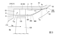
例えば、図3に示すように、内周部材本体40Hの下流側の端縁P2´が、フローガイド50の始点Pc´よりも上流側に位置している構成を採ることも可能である。このように構成することで、フローガイド50の始点Pc´から直ちに内径の拡大率を大きくしても剥離が発生しにくくなり、排気室を軸線O方向にも径方向にも小型化することができ、蒸気タービン全体の小型化も可能になる。
<First modification example>
For example, as shown in FIG. 3, it is also possible to adopt a configuration in which the downstream end edge P2' of the inner circumferential member
<第二変形例>
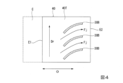
さらに、支持部30の変形例として、図4及び図5に示す構成を採ることも可能である。当該図の例では、支持部30Bは、下流側に向かうに従って、ロータ1の回転方向Drの後方側に向かうように湾曲している。つまり、これら支持部30Bは、回転方向Drの前方側に向かって凸となっている。また、支持部30Bは、キャビティC内における吐出口E2側に偏った位置に設けられている。
<Second modification example>
Furthermore, as a modified example of the
ここで、キャビティC内に流れ込む流れには、ロータ1の回転に伴って、当該回転方向Drに旋回する旋回流成分が含まれている。上記構成では、支持部30Bによってこの旋回流成分が低減され、支持部30Bの下流側では、流れに含まれる軸線O方向成分が多くなる。これにより、吐出口E2から吹き出される流れによるコアンダ効果をより一層促進することができる。したがって、流れを内周面21Sに対してさらに追従させることができる。その結果、流れの剥離が生じる可能性をさらに低減することができる。
Here, the flow flowing into the cavity C includes a swirling flow component that swirls in the rotation direction Dr as the
さらに、上記構成によれば、支持部30Bが吐出口E2側に偏った位置に設けられていることから、吐出口E2から吹き出される流れの方向を安定的に制御することができる。一方で、支持部30Bが抽気口E1側に偏った位置に設けられている場合には、吐出口E2に到達する前にキャビティC内で支持部30B自体による流れの乱れが生じてしまい、吐出口E2の下流側でコアンダ効果を安定して発現させることができない可能性がある。上記構成によれば、このような可能性を低減することができる。
Furthermore, according to the above configuration, since the
<第二実施形態>
次いで、本開示の第二実施形態について、図6を参照して説明する。なお、上記の第一実施形態と同様の構成については同一の符号を付し、詳細な説明を省略する。同図に示すように、本実施形態では、上述の排気室によって排気方向を変更する蒸気タービン100に代えて、軸線O方向に排気する軸流タービン200に、キャビティC、及び内周部材40が適用されている。軸線O方向に排気する軸流タービン200には、蒸気タービンに限られず、ガスタービンも含まれる。軸流タービン200は、最終段動翼列12D´の下流側に、前述の排気室に代えて内径側壁面D1を有するディフューザDを備える。本実施形態においても、タービンケーシング70の内周面70S(車室内周面)における最終段動翼列12D´に対向する部分に、キャビティC´が形成されている。さらに、このキャビティC´は、内周部材本体40H´によって径方向内側から覆われている。内周部材本体40H´は、キャビティC´の内周面に対して支持部30´によって固定されている。また、最終段動翼列12D´の下流側には、ディフューザDの内径側壁面D1を支持するストラット60が設けられている。
<Second embodiment>
Next, a second embodiment of the present disclosure will be described with reference to FIG. 6. Note that the same configurations as those in the first embodiment described above are given the same reference numerals, and detailed explanations will be omitted. As shown in the figure, in this embodiment, instead of the
上記構成によれば、最終段動翼列12D´を通過してディフューザDに流入した流れの剥離を抑制できるため、従来よりもディフューザDにおける断面積の拡大率を大きくすることができる。したがって、ディフューザDの軸線O方向における寸法を短縮できる。すなわち軸流タービン200の全長を短くし、小型化することが可能になる。
According to the above configuration, separation of the flow that has passed through the final
以上、本開示の第二実施形態について説明した。なお、本開示の要旨を逸脱しない限りにおいて、上記の構成に種々の変更や改修を施すことが可能である。 The second embodiment of the present disclosure has been described above. Note that various changes and modifications can be made to the above configuration without departing from the gist of the present disclosure.
<第三実施形態>
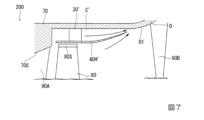
次いで、本開示の第三実施形態について、図7を参照して説明する。なお、上記の各実施形態と同様の構成については同一の符号を付し、詳細な説明を省略する。本実施形態では、軸流タービン200のタービンケーシング70における中間段動翼列80に対応する領域に、上記各実施形態で説明したキャビティC´が形成されている。キャビティC´は、内周部材本体40H´によって径方向内側から覆われている。内周部材本体40H´は、キャビティC´の内周面に対して支持部30´によって固定されている。また、中間段動翼列80の上流側、及び下流側には、それぞれ静翼保持リング(図示せず)を介して中間段静翼列90A,90Bが設けられている。また、中間段動翼列80の先端にはシュラウド80Sが設けられている。
<Third embodiment>
Next, a third embodiment of the present disclosure will be described with reference to FIG. 7. Note that the same configurations as in each of the above embodiments are designated by the same reference numerals, and detailed description thereof will be omitted. In this embodiment, the cavity C' described in each of the above embodiments is formed in a region of the
上記構成によれば、中間段動翼列80を通過する流れの剥離が低減されることで、タービンとしての軸流タービン200の性能をさらに向上させることができる。また、当該中間段動翼列80の下流側での剥離発生を抑制できるため、車室内径の拡大率を大きくとることが可能になる。逆に言えば当該中間段動翼列80よりも下流側に位置する他の動翼列の翼高さと比較して当該動翼列80の翼高さを小さく抑えることができる。すなわち、同じ径の最終段動翼列を持つ従来の軸流タービンと比較してタービンの軸長を短く構成して、軸流タービンを小型化できる。
According to the above configuration, separation of the flow passing through the intermediate
以上、本開示の第三実施形態について説明した。なお、本開示の要旨を逸脱しない限りにおいて、上記の構成に種々の変更や改修を施すことが可能である。 The third embodiment of the present disclosure has been described above. Note that various changes and modifications can be made to the above configuration without departing from the gist of the present disclosure.
<第四実施形態>
次いで、本開示の第四実施形態について、図8を参照して説明する。なお、上記の各実施形態と同様の構成については同一の符号を付し、詳細な説明を省略する。本実施形態では、第一実施形態で説明した蒸気タービン100において、車室内周面21Sに上述のキャビティCが形成されていない。車室内周面21Sは、上流側から下流側に向かうに従って全体として次第に拡径している。なお、車室内周面21Sにおける最終段動翼列12Dに対向する部分は軸線Oと平行に延びている。なお、フィンシールを設けるために、当該部分を階段状に形成する構成を採ることも可能である。
<Fourth embodiment>
Next, a fourth embodiment of the present disclosure will be described with reference to FIG. 8. Note that the same configurations as in each of the above embodiments are designated by the same reference numerals, and detailed description thereof will be omitted. In this embodiment, in the
さらに、車室内周面21Sにおける最終段動翼列12Dよりも下流側には、内周部材40bが設けられている。内周部材40bは、内周部材本体40Hと、当該内周部材本体40Hを車室内周面21S上で支持する支持部30と、を有している。内周部材本体40Hは、車室内周面21Sに沿って延びている。つまり、内周部材本体40Hは、上流側から下流側に向かうに従って径方向内側から外側に向かって延びている。支持部30は、車室内周面21Sと内周部材本体40Hの外周面とを接続している。なお、支持部30の態様として、上述の第一実施形態や、第一実施形態の第二変形例で説明した構成を採ることが可能である。
Further, an inner
上記構成によれば、車室2内部を流れる流体の一部は、抽気口E1を通じて内周部材本体40Hと車室内周面21Sとの間の空間に流れ込む。当該空間に流れ込んだ流体は、吐出口E2から下流側に向かって吹き出される。この流れにより、内周部材本体40Hの内周面に沿う流れは、当該吐出口E2から吹き出した流れに対してコアンダ効果によって引き付けられる。したがって、内周部材本体40Hの下流側で、流体が車室内周面21Sから剥離してしまう可能性を低減することができる。また、上記構成では、車室2内部を流れる流体をキャビティC等によって捕捉することなく、内周部材本体40Hによって直接的にこれを案内することができる。これにより、キャビティCに流体が流れ込む際に生じる損失の発生を回避しつつ、流れの剥離を抑制することができる。
According to the above configuration, a part of the fluid flowing inside the
以上、本開示の第四実施形態について説明した。なお、本開示の要旨を逸脱しない限りにおいて、上記の構成に種々の変更や改修を施すことが可能である。 The fourth embodiment of the present disclosure has been described above. Note that various changes and modifications can be made to the above configuration without departing from the gist of the present disclosure.
<第五実施形態>
次いで、本開示の第五実施形態について、図9を参照して説明する。なお、上記の各実施形態と同様の構成については同一の符号を付し、詳細な説明を省略する。本実施形態では、軸流タービン200のタービンケーシング70における中間段動翼列80に対応する領域に、上記各実施形態で説明した内周部材40cが設けられている。また、本実施形態では、タービンケーシング70の内周面70S(車室内周面)に上述のキャビティC´が形成されていない。つまり、内周面70Sは、上流側から下流側に向かうに従って全体として次第に拡径している。なお、内周面70Sにおける中間段動翼列80に対向する部分は軸線Oと平行に延びている。なお、フィンシールを設けるために、当該部分を階段状に形成する構成を採ることも可能である。また、中間段動翼列80の上流側、及び下流側には、それぞれ静翼保持リング(図示せず)を介して中間段静翼列90A,90Bが設けられている。
<Fifth embodiment>
Next, a fifth embodiment of the present disclosure will be described with reference to FIG. 9. Note that the same configurations as in each of the above embodiments are designated by the same reference numerals, and detailed description thereof will be omitted. In this embodiment, the inner
内周部材40cは、内周面70Sにおける中間段動翼80の下流側に設けられている。内周部材40cは、内周部材本体40Hと、支持部30と、を有している。内周部材本体40Hは、内周面70Sに沿って延びている。つまり、内周部材本体40Hは、上流側から下流側に向かうに従って径方向内側から外側に向かって延びている。支持部30は、車室内周面21Sと内周部材本体40Hの外周面とを接続している。なお、支持部30の態様として、上述の第一実施形態や、第一実施形態の第二変形例で説明した構成を採ることが可能である。
The inner
上記構成によれば、中間段動翼列80を通過する流れの剥離が低減されることで、タービンとしての軸流タービン200の性能をさらに向上させることができる。また、当該中間段動翼列80の下流側での剥離発生を抑制できるため、車室内径の拡大率を大きくとることが可能になる。逆に言えば当該中間段動翼列80よりも下流側に位置する他の動翼列の翼高さと比較して当該動翼列80の翼高さを小さく抑えることができる。すなわち、同じ径の最終段動翼列を持つ従来の軸流タービンと比較してタービンの軸長を短く構成して、軸流タービンを小型化できる。
According to the above configuration, separation of the flow passing through the intermediate
また、上記構成では、タービンケーシング70の内部を流れる流体をキャビティC等によって捕捉することなく、内周部材本体40Hによって直接的にこれを案内することができる。これにより、キャビティCに流体が流れ込む際に生じる損失の発生を回避しつつ、流れの剥離を抑制することができる。
Further, with the above configuration, the fluid flowing inside the
以上、本開示の第五実施形態について説明した。なお、本開示の要旨を逸脱しない限りにおいて、上記の構成に種々の変更や改修を施すことが可能である。 The fifth embodiment of the present disclosure has been described above. Note that various changes and modifications can be made to the above configuration without departing from the gist of the present disclosure.
<付記>
各実施形態に記載のタービンは、例えば以下のように把握される。
<Additional notes>
The turbine described in each embodiment is understood as follows, for example.
(1)第1の態様に係るタービン100は、軸線O回りに回転可能な回転軸11、及び該回転軸11の外周面に設けられた動翼列12を有するロータ1と、該ロータ1を外周側から覆うとともに前記軸線O方向の下流側に向かうにしたがって径方向外側に延びる車室内周面21Sを有する車室2と、前記車室内周面21Sを内周側から覆うことで、上流側で前記車室内周面21Sとの間に抽気口E1を形成し、下流側に吐出口E2を形成する内周部材本体40Hと、を備え、前記吐出口E2は、前記抽気口E1、及び前記吐出口E2は、前記軸線Oを中心とする環状をなし、前記吐出口E2の流路断面積は、前記抽気口E1の流路断面積よりも小さく設定されている。
(1) The
上記構成によれば、車室2内部を流れる流体の一部は、抽気口E1を通じて内周部材本体40Hと車室内周面21Sとの間の空間に流れ込む。当該空間に流れ込んだ流体は、吐出口E2から下流側に向かってジェット噴流として吹き出される。この流れにより、内周部材本体40Hの内周面に沿う流れは、コアンダ効果によって当該吐出口E2から吹き出した流れに引き付けられる。したがって、内周部材本体40Hの下流側で、流体が車室内周面21Sから剥離してしまう可能性を低減することができる。また、上記構成では、抽気口E1、及び吐出口E2が軸線Oを中心とする環状をなしていることから、車室2内部における全周にわたって上記のような剥離の発生を抑制することができる。さらに、上記構成によれば、吐出口E2の流路断面積は、抽気口の流路断面積よりも小さく設定されている。これにより、抽気口E1から吐出口E2に向かう流体の流速が上がる。その結果、吐出口E2から吹き出す流体の流速を、内周部材本体40Hよりも内周側を流れる流体の流速よりも高くすることができる。したがって、内周部材本体40Hの下流側で流れの剥離が生じる可能性をさらに低減することができる。
According to the above configuration, a part of the fluid flowing inside the
(2)第2の態様に係るタービン100では、前記車室内周面21Sには、該車室内周面21Sにおける前記動翼列12に対向する部分に形成されて径方向外側に凹むとともに前記軸線Oを中心とする環状をなすキャビティCが形成され、前記内周部材本体40Hは、前記キャビティCを内周側から覆うように設けられている。
(2) In the
上記構成によれば、車室2内部を流れる流体の一部は、抽気口E1を通じてキャビティC内に流れ込む。キャビティC内に流れ込んだ流体は、吐出口E2から下流側に向かって吹き出される。これにより、内周部材本体40Hの内周面に沿う流れは、当該吐出口E2から吹き出した流れに対してコアンダ効果によって引き付けられる。したがって、内周部材本体40Hの下流側で、流体が車室内周面21Sから剥離してしまう可能性を低減することができる。また、上記構成では、抽気口E1、及び吐出口E2が軸線Oを中心とする環状をなしていることから、車室2内部における全周にわたって上記のような剥離の発生を抑制することができる。さらに、上記構成によれば、吐出口E2の流路断面積は、抽気口の流路断面積よりも小さく設定されている。これにより、抽気口E1から吐出口E2に向かうに従ってキャビティC内を流れる流体の流速が上がる。その結果、吐出口E2から吹き出す流体の流速を、キャビティC外を流れる流体の流速よりも高くすることができる。したがって、キャビティCの下流側で流れの剥離が生じる可能性をさらに低減することができる。
According to the above configuration, a part of the fluid flowing inside the
(3)第3の態様に係るタービン100では、前記車室内周面21Sは、上流側から下流側に向かうに従って次第に拡径し、前記内周部材本体40Hは、前記車室内周面21Sに沿って延びている。
(3) In the
上記構成によれば、車室2内部を流れる流体の一部は、漏れ流れとなって動翼列12の先端と車室内周面21Sとの間を通過した後、抽気口E1を通じて内周部材本体40Hと車室内周面21Sとの間の空間に流れ込む。当該空間に流れ込んだ流体は、吐出口E2から下流側に向かって吹き出される。この流れにより、内周部材本体40Hの内周面に沿う流れは、当該吐出口E2から吹き出した流れに対してコアンダ効果によって引き付けられる。つまり、漏れ流れを単に主流に戻すだけでなく、コアンダ効果を発現させるためにこれを有効に活用する。したがって、内周部材本体40Hの下流側で、流体が車室内周面21Sから剥離してしまう可能性を低減することができる。
According to the above configuration, a part of the fluid flowing inside the
(4)第4の態様に係るタービン100では、前記軸線Oを含む断面視で、前記内周部材本体40Hの前記吐出口E2側の端縁P2における接線Lcは、下流側に向かうに従って前記軸線Oから離間する方向に延びている。
(4) In the
上記構成によれば、内周部材本体40Hの吐出口E2側の端縁P2における接線Lcが、下流側に向かうに従って軸線Oから離間する方向に延びていることから、当該内周部材本体40Hの下流側では、吐出口E2から吹き出される流れを車室内周面21Sに沿わせることができる。これにより、コアンダ効果の発現が促進され、流れをより一層車室内周面21S側に引き寄せることができる。つまり、流れの剥離が生じる可能性をさらに低減することができる。
According to the above configuration, the tangent Lc at the edge P2 on the discharge port E2 side of the inner circumferential member
(5)第5の態様に係るタービン100は、前記内周部材本体40Hの外周面と前記車室内周面21Sとを接続することで該内周部材本体40Hを支持する支持部30をさらに有する。
(5) The
上記構成によれば、支持部30によって、内周部材本体40Hを車室内周面21S上で安定的に支持することができる。
According to the above configuration, the
(6)第6の態様に係るタービン100では、前記支持部30Bは、上流側から下流側に向かうに従って、前記回転軸11の回転方向Dr後方側に向かって湾曲している。
(6) In the
上記構成によれば、支持部30Bが下流側に向かうに従って回転方向Dr後方側に湾曲している。ここで、前記内周部材本体40Hの外周面と前記車室内周面21Sの間に流れ込む流れには、回転軸11の回転に伴って、当該回転方向Drに旋回する旋回流成分が含まれている。上記構成では、支持部30Bによってこの旋回流成分が低減され、支持部30Bの下流側では、流れに含まれる軸線O方向成分が多くなる。これにより、吐出口E2から吹き出される流れによるコアンダ効果をより一層促進することができる。したがって、流れを車室内周面21Sに対してさらに追従させることができる。その結果、流れの剥離が生じる可能性をさらに低減することができる。
According to the above configuration, the
(7)第7の態様に係るタービン100では、前記支持部30Bは、前記内周部材本体40Hにおける前記吐出口E2側に偏った位置に設けられている。
(7) In the
上記構成によれば、支持部30Bが吐出口E2側に偏った位置に設けられていることから、吐出口E2から吹き出される流れの方向を安定的に制御することができる。一方で、支持部30Bが抽気口E1側に偏った位置に設けられている場合には、吐出口E2に到達する前に流れの乱れが生じてしまい、吐出口E2の下流側でコアンダ効果を安定して発現させることができない可能性がある。上記構成によれば、このような可能性を低減することができる。
According to the above configuration, since the
(8)第8の態様に係るタービン100では、前記動翼列12は、蒸気タービンの最終段動翼列12Dであり、前記車室内周面21Sは、該最終段動翼列12Dの下流側に設けられたフローガイド50の内周面を含む。
(8) In the
上記構成によれば、流れの剥離が低減されることで、フローガイド50の軸線O方向における寸法を短くすることができる。その結果、装置全体の占有面積を削減したり、製造コストを低減したりすることが可能となる。
According to the above configuration, the size of the
(9)第9の態様に係るタービンでは、前記内周部材本体40Hの前記吐出口E2側における端縁P2は、前記軸線Oに対する径方向から見て、前記フローガイド50の始点Pcよりも下流側に位置している。
(9) In the turbine according to the ninth aspect, an end edge P2 of the inner circumferential member
上記構成によれば、内周部材本体の吐出口E2側における端縁P2が、フローガイド50の始点Pcよりも下流側に位置している。これにより、吐出口E2から吹き出される流れを、車室内周面21Sに対してさらに追従させることができる。その結果、流れの剥離が生じる可能性をさらに低減することができる。
According to the above configuration, the end edge P2 of the inner peripheral member main body on the discharge port E2 side is located downstream of the starting point Pc of the
(10)第10の態様に係るタービン200では、前記動翼列は、軸流タービン200の中間段動翼列80である。
(10) In the
上記構成によれば、中間段動翼列80を通過する流れの剥離が低減されることで、タービンとしての軸流タービン200の性能をさらに向上させることができる。また、当該中間段動翼列80よりも上流側に位置する他の動翼列の翼高さを小さく抑えることができる。その結果、タービン200を小型化することができる。
According to the above configuration, separation of the flow passing through the intermediate
(11)第11の態様に係るタービン200では、前記動翼列は、軸流タービン200の最終段動翼列12D´である。
(11) In the
上記構成によれば、最終段動翼列12D´を通過する流れの剥離が低減されることで、タービンとしての軸流タービン200の性能をさらに向上させることができる。また、当該最終段動翼列12D´よりも上流側に位置する他の動翼列の翼高さを小さく抑えることができる。その結果、タービン200を小型化することができる。
According to the above configuration, the separation of the flow passing through the final stage
100 蒸気タービン(タービン)
200 軸流タービン(タービン)
1 ロータ
2 車室
2E 供給管
11 回転軸
12 動翼列
12D,12D´ 最終段動翼列
21 内車室
21H 内車室本体
21R 静翼保持リング
21S 内周面(車室内周面)
22 排気ケーシング
22A ベアリングコーン
22B 外車室
30,30B,30´ 支持部
40,40´,40b,40c 内周部材
40H,40H´ 内周部材本体
40S 案内面
40T 流路形成面
50 フローガイド
50S フローガイドの内周面
60 ストラット
70 タービンケーシング
80 中間段動翼列
90A,90B 中間段静翼列
C,C´ キャビティ
C1 キャビティ内周面
C2 キャビティ上流面
Dr 回転方向
O 軸線
P1,P2 端縁
Pc フローガイドの始点
100 Steam turbine (turbine)
200 Axial flow turbine (turbine)
1
22
Claims (9)
該ロータを外周側から覆うとともに前記軸線方向の下流側に向かうにしたがって径方向外側に延びる車室内周面を有する車室と、
前記車室内周面を内周側から覆うことで、上流側で前記車室内周面との間に抽気口を形成し、下流側に吐出口を形成する内周部材本体と、
を備え、
前記内周部材本体は、前記複数の動翼列のうちで最も前記下流側の最終段動翼列の少なくとも一部と、前記軸線に対する径方向で対向し、
前記抽気口は、前記最終段動翼列の前記下流側の端よりも前記上流側に位置し、
前記吐出口は、前記最終段動翼列よりも下流側に位置し、
前記抽気口、及び前記吐出口は、前記軸線を中心とする環状をなし、
前記吐出口の流路断面積は、前記抽気口の流路断面積よりも小さく設定されているタービン。 A rotor having a rotating shaft rotatable around the axis, and a plurality of rotor blade rows provided at intervals in the axial direction on the outer circumferential surface of the rotating shaft;
a vehicle interior having a vehicle interior circumferential surface that covers the rotor from the outer peripheral side and extends radially outward toward the downstream side in the axial direction;
an inner peripheral member main body that covers the peripheral surface of the vehicle interior from the inner peripheral side to form a bleed port between the peripheral surface of the vehicle interior on the upstream side and a discharge port on the downstream side;
Equipped with
The inner circumferential member main body faces at least a portion of the final stage rotor blade row on the most downstream side among the plurality of rotor blade rows in a radial direction with respect to the axis,
The bleed port is located on the upstream side of the downstream end of the final stage rotor blade row,
The discharge port is located downstream of the final stage rotor blade row,
The bleed port and the discharge port have an annular shape centered on the axis,
A flow passage cross-sectional area of the discharge port is set to be smaller than a flow passage cross-sectional area of the bleed port.
前記内周部材本体は、前記キャビティを内周側から覆うように設けられている請求項1に記載のタービン。 A cavity is formed in the vehicle interior peripheral surface at a portion of the vehicle interior peripheral surface facing the rotor blade row, and is recessed radially outward and has an annular shape centered on the axis;
The turbine according to claim 1, wherein the inner peripheral member main body is provided to cover the cavity from the inner peripheral side.
前記内周部材本体は、前記車室内周面に沿って延びている請求項1に記載のタービン。 The circumferential surface of the vehicle interior gradually expands in diameter from the upstream side toward the downstream side,
The turbine according to claim 1, wherein the inner circumferential member main body extends along the inner circumferential surface of the vehicle interior.
Priority Applications (6)
| Application Number | Priority Date | Filing Date | Title |
|---|---|---|---|
| JP2020015615A JP7368260B2 (en) | 2020-01-31 | 2020-01-31 | turbine |
| DE112021000804.8T DE112021000804T5 (en) | 2020-01-31 | 2021-01-26 | TURBINE |
| US17/796,377 US11852032B2 (en) | 2020-01-31 | 2021-01-26 | Turbine |
| CN202180011322.4A CN115003898B (en) | 2020-01-31 | 2021-01-26 | Turbine engine |
| PCT/JP2021/002635 WO2021153556A1 (en) | 2020-01-31 | 2021-01-26 | Turbine |
| KR1020227027801A KR20220123123A (en) | 2020-01-31 | 2021-01-26 | turbine |
Applications Claiming Priority (1)
| Application Number | Priority Date | Filing Date | Title |
|---|---|---|---|
| JP2020015615A JP7368260B2 (en) | 2020-01-31 | 2020-01-31 | turbine |
Publications (2)
| Publication Number | Publication Date |
|---|---|
| JP2021124021A JP2021124021A (en) | 2021-08-30 |
| JP7368260B2 true JP7368260B2 (en) | 2023-10-24 |
Family
ID=77079379
Family Applications (1)
| Application Number | Title | Priority Date | Filing Date |
|---|---|---|---|
| JP2020015615A Active JP7368260B2 (en) | 2020-01-31 | 2020-01-31 | turbine |
Country Status (6)
| Country | Link |
|---|---|
| US (1) | US11852032B2 (en) |
| JP (1) | JP7368260B2 (en) |
| KR (1) | KR20220123123A (en) |
| CN (1) | CN115003898B (en) |
| DE (1) | DE112021000804T5 (en) |
| WO (1) | WO2021153556A1 (en) |
Families Citing this family (1)
| Publication number | Priority date | Publication date | Assignee | Title |
|---|---|---|---|---|
| JP7368260B2 (en) * | 2020-01-31 | 2023-10-24 | 三菱重工業株式会社 | turbine |
Citations (12)
| Publication number | Priority date | Publication date | Assignee | Title |
|---|---|---|---|---|
| DE10255389A1 (en) | 2002-11-28 | 2004-06-09 | Alstom Technology Ltd | Low pressure steam turbine has multi-channel diffuser with inner and outer diffuser rings to take blade outflow out of it |
| JP2007120499A (en) | 2005-10-25 | 2007-05-17 | General Electric Co <Ge> | Multi-slot inter-turbine duct assembly for use in turbine engine |
| US20100226767A1 (en) | 2007-03-13 | 2010-09-09 | Sascha Becker | Diffuser arrangement |
| JP2011099380A (en) | 2009-11-06 | 2011-05-19 | Hitachi Ltd | Axial flow turbine |
| JP2011169172A (en) | 2010-02-16 | 2011-09-01 | Mitsubishi Heavy Ind Ltd | Turbine |
| JP2011220125A (en) | 2010-04-05 | 2011-11-04 | Toshiba Corp | Axial flow turbine |
| JP2012149614A (en) | 2011-01-21 | 2012-08-09 | Hitachi Ltd | Axial flow turbine |
| WO2013027239A1 (en) | 2011-08-24 | 2013-02-28 | 株式会社 日立製作所 | Axial flow turbine |
| JP2013148059A (en) | 2012-01-23 | 2013-08-01 | Toshiba Corp | Steam turbine |
| WO2014010287A1 (en) | 2012-07-11 | 2014-01-16 | 三菱重工業株式会社 | Axial flow exhaust turbine |
| JP2017008756A (en) | 2015-06-18 | 2017-01-12 | 三菱日立パワーシステムズ株式会社 | Axial flow turbine |
| JP2019157680A (en) | 2018-03-09 | 2019-09-19 | 三菱重工業株式会社 | Steam turbine device |
Family Cites Families (24)
| Publication number | Priority date | Publication date | Assignee | Title |
|---|---|---|---|---|
| FR1502832A (en) * | 1966-09-26 | 1967-11-24 | Nord Aviation | Diffusion faired propeller |
| GB1291943A (en) * | 1970-02-11 | 1972-10-04 | Secr Defence | Improvements in or relating to ducted fans |
| NL7811364A (en) * | 1978-11-17 | 1980-05-20 | Tno | DIFFUSOR IN PARTICULAR WITH LARGE TOP ANGLE. |
| JPS5965907U (en) * | 1982-10-25 | 1984-05-02 | 富士電機株式会社 | Turbine exhaust diffuser |
| DE4422700A1 (en) | 1994-06-29 | 1996-01-04 | Abb Management Ag | Diffuser for turbomachinery |
| JPH08260905A (en) * | 1995-03-28 | 1996-10-08 | Mitsubishi Heavy Ind Ltd | Exhaust diffuser for axial turbine |
| EP0903468B1 (en) * | 1997-09-19 | 2003-08-20 | ALSTOM (Switzerland) Ltd | Gap sealing device |
| DE10037684A1 (en) | 2000-07-31 | 2002-02-14 | Alstom Power Nv | Low pressure steam turbine with multi-channel diffuser |
| RU2256801C2 (en) | 2003-06-24 | 2005-07-20 | Открытое акционерное общество "Авиадвигатель" | Gas-turbine engine |
| JP2009036118A (en) | 2007-08-02 | 2009-02-19 | Mitsubishi Heavy Ind Ltd | Axial-flow exhaust gas turbine |
| JP2009103099A (en) | 2007-10-25 | 2009-05-14 | Toshiba Corp | Steam turbine |
| JP2010216321A (en) * | 2009-03-16 | 2010-09-30 | Hitachi Ltd | Moving blade of steam turbine, and steam turbine using the same |
| US8161749B2 (en) | 2009-04-07 | 2012-04-24 | General Electric Company | Cooled exhaust hood plates for reduced exhaust loss |
| JP5023125B2 (en) * | 2009-09-28 | 2012-09-12 | 株式会社日立製作所 | Axial flow turbine |
| US9249687B2 (en) * | 2010-10-27 | 2016-02-02 | General Electric Company | Turbine exhaust diffusion system and method |
| JP6097487B2 (en) * | 2012-03-16 | 2017-03-15 | 三菱重工業株式会社 | Centrifugal pump |
| JP5936403B2 (en) * | 2012-03-22 | 2016-06-22 | 三菱日立パワーシステムズ株式会社 | Turbine |
| JP6432110B2 (en) | 2014-08-29 | 2018-12-05 | 三菱日立パワーシステムズ株式会社 | gas turbine |
| JP2016217285A (en) | 2015-05-22 | 2016-12-22 | 株式会社東芝 | Steam turbine |
| US10883387B2 (en) * | 2016-03-07 | 2021-01-05 | General Electric Company | Gas turbine exhaust diffuser with air injection |
| JP6821426B2 (en) * | 2016-12-26 | 2021-01-27 | 三菱重工業株式会社 | Diffuser, turbine and gas turbine |
| JP6910864B2 (en) * | 2017-06-22 | 2021-07-28 | 東芝ライフスタイル株式会社 | Electric cleaning device |
| JP7119713B2 (en) | 2018-07-27 | 2022-08-17 | 株式会社リコー | image forming device |
| JP7368260B2 (en) * | 2020-01-31 | 2023-10-24 | 三菱重工業株式会社 | turbine |
-
2020
- 2020-01-31 JP JP2020015615A patent/JP7368260B2/en active Active
-
2021
- 2021-01-26 CN CN202180011322.4A patent/CN115003898B/en active Active
- 2021-01-26 DE DE112021000804.8T patent/DE112021000804T5/en active Pending
- 2021-01-26 WO PCT/JP2021/002635 patent/WO2021153556A1/en active Application Filing
- 2021-01-26 KR KR1020227027801A patent/KR20220123123A/en not_active Application Discontinuation
- 2021-01-26 US US17/796,377 patent/US11852032B2/en active Active
Patent Citations (12)
| Publication number | Priority date | Publication date | Assignee | Title |
|---|---|---|---|---|
| DE10255389A1 (en) | 2002-11-28 | 2004-06-09 | Alstom Technology Ltd | Low pressure steam turbine has multi-channel diffuser with inner and outer diffuser rings to take blade outflow out of it |
| JP2007120499A (en) | 2005-10-25 | 2007-05-17 | General Electric Co <Ge> | Multi-slot inter-turbine duct assembly for use in turbine engine |
| US20100226767A1 (en) | 2007-03-13 | 2010-09-09 | Sascha Becker | Diffuser arrangement |
| JP2011099380A (en) | 2009-11-06 | 2011-05-19 | Hitachi Ltd | Axial flow turbine |
| JP2011169172A (en) | 2010-02-16 | 2011-09-01 | Mitsubishi Heavy Ind Ltd | Turbine |
| JP2011220125A (en) | 2010-04-05 | 2011-11-04 | Toshiba Corp | Axial flow turbine |
| JP2012149614A (en) | 2011-01-21 | 2012-08-09 | Hitachi Ltd | Axial flow turbine |
| WO2013027239A1 (en) | 2011-08-24 | 2013-02-28 | 株式会社 日立製作所 | Axial flow turbine |
| JP2013148059A (en) | 2012-01-23 | 2013-08-01 | Toshiba Corp | Steam turbine |
| WO2014010287A1 (en) | 2012-07-11 | 2014-01-16 | 三菱重工業株式会社 | Axial flow exhaust turbine |
| JP2017008756A (en) | 2015-06-18 | 2017-01-12 | 三菱日立パワーシステムズ株式会社 | Axial flow turbine |
| JP2019157680A (en) | 2018-03-09 | 2019-09-19 | 三菱重工業株式会社 | Steam turbine device |
Also Published As
| Publication number | Publication date |
|---|---|
| JP2021124021A (en) | 2021-08-30 |
| KR20220123123A (en) | 2022-09-05 |
| CN115003898B (en) | 2024-07-02 |
| US20230111300A1 (en) | 2023-04-13 |
| CN115003898A (en) | 2022-09-02 |
| WO2021153556A1 (en) | 2021-08-05 |
| US11852032B2 (en) | 2023-12-26 |
| DE112021000804T5 (en) | 2023-01-19 |
Similar Documents
| Publication | Publication Date | Title |
|---|---|---|
| JP6334258B2 (en) | Steam turbine | |
| JP6847673B2 (en) | Turbine exhaust chamber | |
| JP2010159667A (en) | Axial flow turbine | |
| CA2927035C (en) | Rotor assembly with wear member | |
| US8561997B2 (en) | Adverse pressure gradient seal mechanism | |
| JP2016121690A (en) | Engine and method of operating engine | |
| WO2019131632A1 (en) | Exhaust chamber and steam turbine | |
| JP7368260B2 (en) | turbine | |
| JP6518526B2 (en) | Axial flow turbine | |
| JP7458947B2 (en) | Steam turbine | |
| PL220635B1 (en) | Exhaust gas diffuser and a turbine | |
| JP2012107619A (en) | Exhaust hood diffuser | |
| JP7054582B2 (en) | Sealing device and turbomachinery | |
| WO2019187435A1 (en) | Gas turbine for aircraft | |
| JP6000142B2 (en) | Rotating machine and gas turbine provided with the same | |
| WO2021199718A1 (en) | Secondary flow suppression structure | |
| KR102223293B1 (en) | Rotating machine, exhaust member of rotating machine | |
| JP2018105221A (en) | Diffuser, turbine and gas turbine | |
| JP6785368B2 (en) | gas turbine | |
| JP7527487B2 (en) | Turbine vanes and steam turbines | |
| JP7294528B2 (en) | Stator blades and aircraft gas turbine engines | |
| JP2019015273A (en) | Turbo machine | |
| RU2396471C1 (en) | Gas turbine engine compressor | |
| JP2015102236A (en) | Seal structure and rotary machine | |
| JP2019143508A (en) | Turbine exhaust hood and turbine |
Legal Events
| Date | Code | Title | Description |
|---|---|---|---|
| A621 | Written request for application examination |
Free format text: JAPANESE INTERMEDIATE CODE: A621 Effective date: 20221111 |
|
| A131 | Notification of reasons for refusal |
Free format text: JAPANESE INTERMEDIATE CODE: A131 Effective date: 20230711 |
|
| A521 | Request for written amendment filed |
Free format text: JAPANESE INTERMEDIATE CODE: A523 Effective date: 20230908 |
|
| TRDD | Decision of grant or rejection written | ||
| A01 | Written decision to grant a patent or to grant a registration (utility model) |
Free format text: JAPANESE INTERMEDIATE CODE: A01 Effective date: 20230926 |
|
| A61 | First payment of annual fees (during grant procedure) |
Free format text: JAPANESE INTERMEDIATE CODE: A61 Effective date: 20231012 |
|
| R150 | Certificate of patent or registration of utility model |
Ref document number: 7368260 Country of ref document: JP Free format text: JAPANESE INTERMEDIATE CODE: R150 |