EP2615331A1 - Dispositif d'ouverture/fermeture - Google Patents
Dispositif d'ouverture/fermeture Download PDFInfo
- Publication number
- EP2615331A1 EP2615331A1 EP11823294.1A EP11823294A EP2615331A1 EP 2615331 A1 EP2615331 A1 EP 2615331A1 EP 11823294 A EP11823294 A EP 11823294A EP 2615331 A1 EP2615331 A1 EP 2615331A1
- Authority
- EP
- European Patent Office
- Prior art keywords
- opening
- axial portion
- arm
- housing
- movable plate
- Prior art date
- Legal status (The legal status is an assumption and is not a legal conclusion. Google has not performed a legal analysis and makes no representation as to the accuracy of the status listed.)
- Granted
Links
- 230000007246 mechanism Effects 0.000 claims abstract description 92
- 230000002265 prevention Effects 0.000 claims description 28
- 239000004973 liquid crystal related substance Substances 0.000 description 29
- 230000007935 neutral effect Effects 0.000 description 15
- 230000001105 regulatory effect Effects 0.000 description 4
- 239000002184 metal Substances 0.000 description 3
- 230000008901 benefit Effects 0.000 description 2
- 239000000463 material Substances 0.000 description 2
- 238000011109 contamination Methods 0.000 description 1
- 230000007423 decrease Effects 0.000 description 1
- 230000003247 decreasing effect Effects 0.000 description 1
- 230000003028 elevating effect Effects 0.000 description 1
- 230000006872 improvement Effects 0.000 description 1
- 238000000034 method Methods 0.000 description 1
- 238000012986 modification Methods 0.000 description 1
- 230000004048 modification Effects 0.000 description 1
- 238000000465 moulding Methods 0.000 description 1
- 230000008569 process Effects 0.000 description 1
- 239000011347 resin Substances 0.000 description 1
- 229920005989 resin Polymers 0.000 description 1
- 230000000717 retained effect Effects 0.000 description 1
- 125000006850 spacer group Chemical group 0.000 description 1
- 230000001360 synchronised effect Effects 0.000 description 1
- 238000003466 welding Methods 0.000 description 1
Images


Classifications
-
- H—ELECTRICITY
- H04—ELECTRIC COMMUNICATION TECHNIQUE
- H04M—TELEPHONIC COMMUNICATION
- H04M1/00—Substation equipment, e.g. for use by subscribers
- H04M1/02—Constructional features of telephone sets
-
- E—FIXED CONSTRUCTIONS
- E05—LOCKS; KEYS; WINDOW OR DOOR FITTINGS; SAFES
- E05D—HINGES OR SUSPENSION DEVICES FOR DOORS, WINDOWS OR WINGS
- E05D3/00—Hinges with pins
- E05D3/06—Hinges with pins with two or more pins
- E05D3/18—Hinges with pins with two or more pins with sliding pins or guides
-
- A—HUMAN NECESSITIES
- A45—HAND OR TRAVELLING ARTICLES
- A45C—PURSES; LUGGAGE; HAND CARRIED BAGS
- A45C11/00—Receptacles for purposes not provided for in groups A45C1/00-A45C9/00
-
- E—FIXED CONSTRUCTIONS
- E05—LOCKS; KEYS; WINDOW OR DOOR FITTINGS; SAFES
- E05D—HINGES OR SUSPENSION DEVICES FOR DOORS, WINDOWS OR WINGS
- E05D11/00—Additional features or accessories of hinges
- E05D11/10—Devices for preventing movement between relatively-movable hinge parts
-
- E—FIXED CONSTRUCTIONS
- E05—LOCKS; KEYS; WINDOW OR DOOR FITTINGS; SAFES
- E05D—HINGES OR SUSPENSION DEVICES FOR DOORS, WINDOWS OR WINGS
- E05D11/00—Additional features or accessories of hinges
- E05D11/10—Devices for preventing movement between relatively-movable hinge parts
- E05D11/1014—Devices for preventing movement between relatively-movable hinge parts for maintaining the hinge in only one position, e.g. closed
-
- F—MECHANICAL ENGINEERING; LIGHTING; HEATING; WEAPONS; BLASTING
- F16—ENGINEERING ELEMENTS AND UNITS; GENERAL MEASURES FOR PRODUCING AND MAINTAINING EFFECTIVE FUNCTIONING OF MACHINES OR INSTALLATIONS; THERMAL INSULATION IN GENERAL
- F16H—GEARING
- F16H21/00—Gearings comprising primarily only links or levers, with or without slides
- F16H21/10—Gearings comprising primarily only links or levers, with or without slides all movement being in, or parallel to, a single plane
-
- G—PHYSICS
- G06—COMPUTING; CALCULATING OR COUNTING
- G06F—ELECTRIC DIGITAL DATA PROCESSING
- G06F1/00—Details not covered by groups G06F3/00 - G06F13/00 and G06F21/00
- G06F1/16—Constructional details or arrangements
- G06F1/1613—Constructional details or arrangements for portable computers
- G06F1/1633—Constructional details or arrangements of portable computers not specific to the type of enclosures covered by groups G06F1/1615 - G06F1/1626
- G06F1/1675—Miscellaneous details related to the relative movement between the different enclosures or enclosure parts
- G06F1/1681—Details related solely to hinges
-
- H—ELECTRICITY
- H04—ELECTRIC COMMUNICATION TECHNIQUE
- H04M—TELEPHONIC COMMUNICATION
- H04M1/00—Substation equipment, e.g. for use by subscribers
- H04M1/02—Constructional features of telephone sets
- H04M1/0202—Portable telephone sets, e.g. cordless phones, mobile phones or bar type handsets
- H04M1/0206—Portable telephones comprising a plurality of mechanically joined movable body parts, e.g. hinged housings
- H04M1/0208—Portable telephones comprising a plurality of mechanically joined movable body parts, e.g. hinged housings characterized by the relative motions of the body parts
- H04M1/0235—Slidable or telescopic telephones, i.e. with a relative translation movement of the body parts; Telephones using a combination of translation and other relative motions of the body parts
- H04M1/0237—Sliding mechanism with one degree of freedom
-
- E—FIXED CONSTRUCTIONS
- E05—LOCKS; KEYS; WINDOW OR DOOR FITTINGS; SAFES
- E05Y—INDEXING SCHEME ASSOCIATED WITH SUBCLASSES E05D AND E05F, RELATING TO CONSTRUCTION ELEMENTS, ELECTRIC CONTROL, POWER SUPPLY, POWER SIGNAL OR TRANSMISSION, USER INTERFACES, MOUNTING OR COUPLING, DETAILS, ACCESSORIES, AUXILIARY OPERATIONS NOT OTHERWISE PROVIDED FOR, APPLICATION THEREOF
- E05Y2999/00—Subject-matter not otherwise provided for in this subclass
-
- H—ELECTRICITY
- H04—ELECTRIC COMMUNICATION TECHNIQUE
- H04M—TELEPHONIC COMMUNICATION
- H04M1/00—Substation equipment, e.g. for use by subscribers
- H04M1/02—Constructional features of telephone sets
- H04M1/0202—Portable telephone sets, e.g. cordless phones, mobile phones or bar type handsets
- H04M1/0206—Portable telephones comprising a plurality of mechanically joined movable body parts, e.g. hinged housings
- H04M1/0208—Portable telephones comprising a plurality of mechanically joined movable body parts, e.g. hinged housings characterized by the relative motions of the body parts
- H04M1/0214—Foldable telephones, i.e. with body parts pivoting to an open position around an axis parallel to the plane they define in closed position
- H04M1/0216—Foldable in one direction, i.e. using a one degree of freedom hinge
Definitions
- the present invention relates to an opening/closing device and more specifically, to an opening/closing device which moves a movable plate with respect to a fixed plate.
- a mobile terminal device includes a first housing to which a numeric keypad, a liquid crystal display device or the like is provided and a second housing to which a liquid crystal display device or the like is provided and capable of being opened and closed with respect to the first housing. Further, as a structure which opens and closes the second housing with respect to the first housing, a folding type in which the first housing and the second housing are connected by a hinge mechanism so that the second housing is rotated with respect to the first housing and a slide type in which the second housing is slid with respect to the first housing are generally used.
- a mobile terminal device has been progressed to have a multifunction, there is provided a device which is capable of receiving Digital Terrestrial Television Broadcasting and the size of the liquid crystal display device has been enlarged. Further, in accordance with providing the multifunction, the number of keys of the keyboard for performing an input process to the mobile terminal device tends to increase so that the size of the keyboard is becoming larger. On the other hand, for the mobile terminal device, improvement of the portability is always desired so that there is a limitation in enlarging the size of the liquid crystal display device and the keyboard.
- the liquid crystal display device when the device is folded, the liquid crystal display device is closed so that there is a problem that the liquid crystal display device cannot be used in the folded state. Further, for the slide type mobile terminal device, although the same problems of the folding type do not occur, there is inevitably an overlapping between the first housing and the second housing at an opened state so that space cannot be efficiently used.
- the opening/closing device disclosed in Patent Document 1 is configured such that the second housing is moved with respect to the first housing by a single arm. As such, the second housing is arbitrarily rotated during the movement so that the moving operation is unstable.
- the present invention is made in light of the above problems, and provides an opening/closing device capable of performing a movement operation of a movable plate with respect to a fixed plate stably and smoothly by a single operation.
- an opening/closing device including an opening/closing mechanism which moves a movable plate between an opened position and a closed position with respect to a fixed plate
- the opening/closing mechanism including a hinge arm including a first axial portion rotatably connected to the fixed plate, a third axial portion rotatably connected to the movable plate, and a slide groove provided between the first axial portion and the third axial portion, and capable of moving the movable plate between the closed position and the opened position with respect to the fixed plate by being rotated around the first axial portion as a center, a link arm including a second axial portion rotatably connected to the fixed plate and a fifth axial portion slidably connected to the slide groove, and a slide arm including a fourth axial portion rotatably connected to the movable plate at an end portion and connected to the fifth axial portion at the other end portion, and wherein when the movable plate is moved between the closed position and the opened position, the fifth axial portion
- a movable plate can be smoothly moved between the closed position and the opened position by a single operation.
- Fig. 1 and Fig. 2 are views for explaining an opening/closing device 10 of the embodiment, while Fig. 3 and Fig. 4 are views for explaining an electronic device 1 in which the opening/closing device 10 is provided.
- the electronic device 1 is, for example, a mobile terminal device and includes a first housing 2, a second housing 3, the opening/closing device 10 and the like.
- a keyboard 5 or the like is provided at an upper surface 2a of the first housing 2.
- a liquid crystal display device or the like is provided at an upper surface 3a of the second housing 3.
- the second housing 3 is movable with respect to the first housing 2 between a closed position and an opened position by providing the opening/closing device 10.
- FIG. 4 shows a state at which the second housing 3 is positioned at the closed position (hereinafter, referred to as a "closed state”), and (B) shows a state at which the second housing 3 is positioned at the opened position (hereinafter, referred to as an "opened state”).
- the second housing 3 overlaps above the first housing 2 at the closed state and thus only the liquid crystal display device 4 is exposed at the surface 3a. Therefore, it is possible to see the liquid crystal display device 4 from outside even at the closed state.
- the first housing 2 and the second housing 3 have the same shape in a plan view and thus the area of the electronic device 1 at the closed state becomes a half of the area of which it is at the opened state in a plan view. Therefore, the electronic device 1 becomes a small size and portability is retained at the closed state.
- the second housing 3 moves from the closed position to the opened position by a rotation of a hinge arm 18, a slide arm 20, a link arm 22 and the like (see Fig. 2 ) composing the opening/closing device 10 to be a state in which the upper surface 2a of the first housing 2 and the upper surface 3a of the second housing 3 are positioned at the same plane.
- the first housing 2 and the second housing 3 do not overlap and are positioned to be in a state in which the housings are laterally disposed on the same plane at the opened state.
- the entire surfaces of the upper surfaces 2a and 3a of the housings 2 and 3, respectively, are exposed upward at the opened state.
- the entirety of the upper surface 2a of the first housing 2 can be used as an area for mounting structural components of the electronic device 1
- the entirety of the upper surface 3a of the second housing 3 can be used as an area for mounting the structural components of the electronic device 1.
- the electronic device 1 provided with the opening/closing device 10 of the embodiment as the entirety of the upper surface of the first housing 2 and the entirety of the upper surface of the second housing 3 can be used as mounting area for the structural components, the space of the housings 2 and 3 can be efficiently used.
- the space of the housings 2 and 3 can be efficiently used.
- the opening/closing device 10 mainly includes a pair of opening/closing mechanisms 11A and 11B, a base shaft 26 and the like.
- the pair of opening/closing mechanisms 11A and 11B are placed to be apart from each other in a Y1, Y2 direction.
- each of the opening/closing mechanisms 11A and 11B is configured to include a fixed plate 12, a movable plate 14, a fixed plate 16, a hinge arm 18, a slide arm 20, a backlash prevention mechanism 21, a link arm 22, a hinge unit 30 and the like.
- the pair of opening/closing mechanism 11A and opening/closing mechanism 11B are configured to have the same structure except that the structures of the fixed plates 12 and 16 are different, the hinge arm 18 of the opening/closing mechanism 11A is provided with a bearing portion 18d, the hinge unit 30 is provided to the opening/closing mechanism 11B.
- Each of the structural components of the opening/closing mechanism 11A and each of the structural components of the opening/closing mechanism 11B are symmetrically provided in a left-right direction (Y1, Y2 direction) in Fig. 1 and Fig. 2 .
- the fixed plates 12 and 16 are fixed to the first housing 2 of the electronic device 1. Specifically, as shown in Fig. 3 , the fixed plates 12 and 16 are fixed at a mounting concave portions 2a formed in a first lower half body 2B of the first housing 2.
- the first housing 2 has a structure of a combination of a first upper half body 2A and the first lower half body 2B. Thus, the first housing 2 is configured to be integral with the fixed plates 12 and 16.
- the fixed plates 12 and 16 are formed by pressing metal plate materials.
- the fixed plate 12 includes a base portion 12a which is fixed to the first lower half body 2B (see Fig. 3 ) and standing portions 12b provided at both sides of the base portion 12a.
- the standing portion 12b at the outside (Y1 direction side) is provided with a pivot hole 12c to which a pivot shaft 19 is to be attached, and the standing portion 12b at the inner side (Y2 direction side) is provided with a pivot hole 12d which bears a bearing portion 18d of the hinge arm 18, which will be explained later.
- the fixed plate 16 has a structure where a base portion 16a and a standing portion 16b are integrally formed.
- the base portion 16a is fixed to the first lower half body 2B (see Fig. 3 ).
- the standing portion 16b is provided with a pivot hole 16c to which a pivot shaft 19 is to be attached, which will be explained later.
- the movable plates 14 are configured to be movable with respect to the fixed plates 12 and 16.
- the movable plates 14 are fixed to the second housing 3 of the electronic device 1. Specifically, as shown in Fig. 3 , the movable plates 14 are fixed to mounting concave portions 3a of a second lower half body 3B of the second housing 3.
- the second housing 3 has a structure of a combination of a second upper half body 3A and the second lower half body 3B, and thus the second housing 3 is configured to be integral with the movable plates 14.
- the movable plate 14 includes an inner plate 23 and an outer plate 24 obtained by pressing metal plate materials, respectively.
- the inner plate 23 has a structure in which a base portion 23a, a standing portion 23b, a top plate portion 23c, and a cover portion 23d are integrally formed.
- the base portion 23a is fixed to the above described second lower half body 3B (see Fig. 3 ).
- the standing portion 23b is provided with a pivot hole 14a which bears a shaft portion 18a of the hinge arm 18, which will be explained later.
- the top plate portion 23c overlaps a top plate portion 24c of the outer plate 24 when the inner plate 23 and the outer plate 24 are combined to form the movable plate 14.
- the outer plate 24 has a structure in which a base portion 24a, a standing portion 24b, the top plate portion 24c and a latch housing portion 24d are integrally formed.
- the base portion 24a is fixed to the second lower half body 3B (see Fig. 3 ).
- the standing portion 24b is provided with pivot holes 14a and 14b.
- the pivot hole 14a bears the shaft portion 18a of the hinge arm 18, which will be explained later.
- the pivot hole 14b bears a slide arm shaft 44 which is connected to the slide arm 20.
- the top plate portion 24c is overlapped with the top plate portion 23c of the inner plate 23. Then, at this overlapped state, the inner plate 23 and the outer plate 24 are integrally formed by welding the top plate portions 23c and 24c.
- the latch housing portion 24d slidably houses a latch 41 which composes the backlash prevention mechanism 21, which will be explained later, in an X1, X2 direction. Further, an arm housing portion (space portion) inside of which the hinge arm 18 is housed in accordance with the rotation is formed at inner sides of plates 23 and 24 at a state where the inner plate 23 and the outer plate 24 are integrally formed.
- the movable plates 14 are placed to be separated in the Y1, Y2 direction.
- the top plate portion 23c or the top plate portion 24c composing either of the movable plates 14 may be formed to extend in the Y1, Y2 direction so that the left and right movable plates 14 are integrally formed to be a single structural component.
- the hinge arm 18 is provided with the shaft portion 18a formed at an upper end portion, a pivot hole 18c formed at a lower end portion, and a slide hole 18b (long hole, slide groove) formed at a position between the shaft portion 18a and the pivot hole 18c.
- the shaft portion 18a formed at the upper end portion of the hinge arm 18 is rotatably connected to the pivot hole 14a formed at the movable plate 14 as described above.
- a portion of the shaft portion 18a of the hinge arm 18 which is rotatably connected to the movable plate 14 is referred to as a "third axial portion A3".
- a base shaft 26 (corresponding to a connection arm) is attached to the pivot hole 18c formed at the lower end portion of the hinge arm 18.
- the bearing portion 18d is formed at the hinge arm 18 positioned at the Y1 direction side in Fig. 2 and the pivot hole 18c is formed at the bearing portion 18d.
- An end portion of the base shaft 26 at the Y1 direction side is inserted into the pivot hole 18c of the bearing portion 18d and is fixed to the bearing portion 18d by a pin 29.
- the hinge arm 18 at the Y1 direction side becomes a structure which integrally rotates with the base shaft 26.
- the hinge arm 18 provided at the opening/closing mechanism 11B (positioned at an arrow Y2 direction) is configured such that a part of the structure of the hinge unit 30 is housed inside the pivot hole 18c formed at the lower end portion. Specifically, a head cam 31 and a hinge plate 35 composing the hinge unit 30 are housed inside the pivot hole 18c.
- the head cam 31 and the hinge plate 35 are provided with protruding portions at outer peripheries and the hinge arm 18 is provided with a concave portion corresponding to the protruding portions within the pivot hole 18c.
- the head cam 31 and the hinge plate 35 integrally rotate with the hinge arm 18 at a state in which the head cam 31 and the hinge plate 35 are housed in the pivot hole 18c.
- the hinge shaft 28 which composes the hinge unit 30 is provided at an end portion of the base shaft 26 at the Y2 direction side. Specifically, when the base shaft 26 is inserted in a holder portion 28b provided at the hinge shaft 28 and is fixed by the pin 29, the base shaft 26 and the hinge shaft 28 are configured to be integrally rotated. In the following, referring to the base shaft 26 means that the hinge shaft 28 is also included, except otherwise instructed.
- the hinge shaft 28 is provided with an oval shaped portion 28a at an end portion in the Y2 direction. Further, the hinge plate 35 provided in the shaft portion 18a is provided with an oval shaped hole 35a having a shape corresponding to the oval shaped portion 28a. The oval shaped portion 28a is engaged into the oval shaped hole 35a of the hinge plate 35. With this structure, the hinge arm 18 integrally rotates with the base shaft 26 through the hinge plate 35 and the hinge shaft 28.
- the hinge unit 30, which will be explained later, includes a hinge housing 34 fixed to the first lower half body 2B (see Fig. 3 ).
- the base shaft 26 is borne by the hinge housing 34.
- the base shaft 26 is borne by the fixed plate 12 and the hinge housing 34 which are fixed to the first lower half body 2B (first housing 2) on the first housing 2.
- a rotation axis of the rotation of the hinge arm 18 with respect to the fixed plates 12 and 16 is referred to as a "first axial portion A1".
- slide arm 20 and the link arm 22, respectively are connected to the slide hole 18b formed between the shaft portion 18a and the pivot hole 18c of the hinge arm 18 as shown in Fig. 5 in an enlarged manner.
- the slide hole 18b is formed to extend in a longitudinal direction at an inner side surface of the hinge arm 18.
- the link arm 22 is provided with a boss portion 22c which slidably engages the slide hole 18b.
- position of the slide hole 18b at which the slide arm 20 and the link arm 22 are connected is capable of moving along the slide hole 18b.
- the portion at which the slide arm 20 and the link arm 22 is connected to the slide hole 18b of the hinge arm 18 is referred to as a "fifth axial portion A5".
- the hinge arm 18 structured as described above has a function to move the movable plate 14 between the closed position and the opened position with respect to the fixed plates 12 and 16 by being rotated around the first axial portion A1 connected to the fixed plate 12 as a center. Further, when the movable plate 14 moves between the closed position and the opened position, the fifth axial portion A5 slides within the slide hole 18b.
- the lower end portion of the slide arm 20 is connected to the fifth axial portion A5. Further, a slide arm shaft 44 is inserted into the pivot hole 20b formed at the upper end portion of the slide arm 20. The slide arm shaft 44 is rotatably borne by the pivot hole 14b formed at the movable plate 14 (see (B) of Fig. 6 ).
- a portion of the slide arm 20 which is rotatably connected to the movable plate 14 is referred to as a "fourth axial portion A4".
- the link arm 22 includes a combination of a link arm main body 22A and a link arm cover 22B.
- the link arm main body 22A is made of metal and the link arm cover 22B is made of resin.
- the link arm main body 22A is formed within the link arm cover 22B by an insert molding. With this structure, the strength of the link arm 22 can be actualized by the link arm main body 22A while smoothness at a surface of the link arm 22 can be actualized by the link arm cover 22B.
- the pivot hole 22a formed at the upper end portion of the link arm 22 is rotatably connected to the slide hole 18b by the pivot shaft 17.
- the pivot hole 22b formed at the lower end portion of the link arm 22 is connected to the pivot hole 12c formed at the fixed plate 12 or the pivot hole 16c formed at the fixed plate 16 by the pivot shaft 19.
- the portion at which the lower end portion of the link arm 22 is connected to the fixed plate 12 or the fixed plate 16 is referred to as a "second axial portion A2".
- the upper end portion of the link arm 22 is rotatably connected to the fifth axial portion A5
- the lower end portion of the link arm 22 is rotatably connected to the second axial portion A2. Therefore, as the upper end portion of the link arm 22 is connected to the fifth axial portion A5, the link arm 22 is configured to be slidable along the slide hole 18b.
- the hinge unit 30 includes the hinge shaft 28, the head cam 31, a slide cam 32, hinge springs 33a and 33b, the hinge housing 34, the hinge plate 35 and the like.
- the hinge shaft 28 is connected to the base shaft 26.
- the hinge shaft 28 is inserted into the hinge housing 34 in the Y2 direction.
- the head cam 31, the slide cam 32 and the like are provided at a portion of the hinge shaft 28 which protrudes toward an inner side of the hinge housing 34.
- the head cam 31 and the hinge plate 35 are provided within the pivot hole 18c of the hinge arm 18 (see Fig. 2 ).
- the hinge arm 18, the base shaft 26, the hinge shaft 28, the head cam 31 and the hinge plate 35 are formed to be integrally rotated.
- the slide cam 32 is provided with a projection portion at an outer periphery and the hinge housing 34 is also provided with a concave portion which engages the projection portion at inside.
- the rotation of the slide cam 32 with respect to the hinge housing 34 is regulated at a state in which the slide cam 32 is housed in the hinge housing 34.
- the pivot hole formed at the slide cam 32 has a diameter such that the hinge shaft 28 is rotatable therein.
- the base shaft 26 is rotatable with respect to the slide cam 32 as well as being slidable in an axis direction of the base shaft 26 (the arrow Y1, Y2 direction).
- the hinge spring has a structure of a combination of the outer hinge spring 33a and the inner hinge spring 33b in this embodiment.
- the hinge springs 33a and 33b are configured such that one end portions are in contact with an inner wall of the hinge housing 34 and the other end portions are in contact with the slide cam 32.
- the elastic forces of the hinge springs 33a and 33b function as a force pushing the slide cam 32 toward the head cam 31.
- contacting surfaces of the head cam 31 and the slide cam 32 are provided with convexo-concave surfaces engaging with each other.
- a running torque is not generated at a position where the top portions of the convex surfaces of each of the cams 31 and 32 are in contact with each other (which is referred to as a "neutral position").
- a running torque is generated between each of the cams 31 and 32 by the elastic force of the hinge spring 33.
- the hinge arm 18 moves between the closed position and the opened position, as described above and is set that an intermediate position of the closed position and the opened position becomes the neutral position of each of the cams 31 and 32, in this embodiment.
- the hinge arm 18 is pushed to be rotated toward the closed position and when the hinge arm 18 is positioned between the intermediate position and the opened position, the hinge arm 18 is pushed to be rotated toward the opened position, by the hinge unit 30. Therefore, the above structured hinge unit 30 has a function of a so-called "cam type semiautomatic hinge".
- the movable plate 14 when opening the movable plate 14 (second housing 3) with respect to the fixed plate 12 (first housing 2), the movable plate 14 automatically moves toward the opened position after the movable plate 14 is operated to be open from the closed position to the neutral position.
- the movable plate 14 when closing the movable plate 14 with respect to the fixed plate 12, the movable plate 14 automatically moves toward the closed position after the movable plate 14 is operated to be closed from the opened position to the neutral position.
- the semiautomatic hinge type hinge unit 30 the operability of the opening/closing device 10 (electronic device 1) can be improved.
- the backlash prevention mechanism 21 is explained. As shown in Figs. 6 and 7 in addition to Fig. 2 , the backlash prevention mechanism 21 includes a slide arm 20, a latch cam 40, a latch 41 and the like. As shown in (A) of Fig. 14 , the backlash prevention mechanism 21 has a function to prevent a generation of a movement (backlash) of the movable plate 14 in a direction shown by an arrow S shown in (B) of Fig. 14 after the movable plate 14 is moved to the opened position.
- the latch cam 40 (see Fig. 6 ) has a substantially cylindrical shape.
- the latch cam 40 has a structure that a cam portion 40b is formed at a part of a circumference portion 40a. Further, the latch cam 40 is provided with a pivot hole 40c and an attachment hole 40d. The latch cam 40 is fixed to the slide arm shaft 44.
- the slide arm shaft 44 is a shaft which is borne by the pivot hole 14b formed at the movable plate 14 (outer plate 24). Oval shaped portions 44a and 44b are formed at both end portions of the slide arm shaft 44.
- the oval shaped portion 44a of the slide arm shaft 44 is connected to the slide arm 20.
- the pivot hole 20b formed at the upper end portion of the slide arm 20 has a shape corresponding to the shape of the oval shaped portion 44a.
- the oval shaped portion 44a is fastened to the pivot hole 20b so that the slide arm shaft 44 is integrally rotated with the slide arm 20.
- the latch plate 43 is attached to an outside surface of the latch cam 40.
- the latch plate 43 is provided with an oval shaped portion 43a and a pair of attachment arms 43b which are to be attached to the attachment hole 40d formed in the latch cam 40.
- the oval shaped portion 43a is configured to correspond to the shape of the oval shaped portion 44b of the slide arm shaft 44.
- the latch cam 40 integrally rotates with the slide arm shaft 44 as the slide arm shaft 44 is fastened to the oval shaped portion 43a of the latch plate 43 which is attached to the latch cam 40.
- the slide arm 20 and the latch cam 40 integrally rotate.
- the latch 41 shown in Fig. 7 has a prism shape and provided with a protruding portion 41a at an end portion facing the latch cam 40.
- the protruding portion 41a has a shape to engage the cam portion 40b formed at the latch cam 40.
- the latch 41 is attached in the latch housing portion 24d formed at the outer plate 24 with the latch spring 42.
- the latch 41 is provided with a spring receive portion 41b at an end portion in an X1 direction side and the latch spring 42 is attached to the spring receive portion 41b.
- the outer plate 24 provided with the latch housing portion 24d structures the movable plate 14 by being welded with the inner plate 23.
- the cover portion 23d formed at the inner plate 23 covers an upper opening portion of the latch housing portion 24d at a state in which the inner plate 23 and the outer plate 24 are in combination.
- the latch 41 is prevented from being removed from the outer plate 24 (movable plate 14).
- the latch cam 40 rotates in accordance with the rotation of the slide arm 20. Further, the latch 41 is configured to always push the protruding portion 41a in the direction (the X1 direction) toward the latch cam 40 by the spring force of the latch spring 42. As shown in (A) of Fig. 13 , the latch cam 40 is rotatable so that the slide arm 20 is also rotatable at a state in which the protruding portion 41a of the latch 41 is pressed to be in contact the circumference portion 40a of the latch cam 40.
- Fig. 8 to Fig. 12 show an operation in which the second housing 3 and the movable plate 14 moves from the closed state to the opened state.
- (A) shows an operation of the electronic device 1
- (B) shows an operation of the opening/closing device 10 to which the backlash prevention mechanism 21 is provided
- (C) shows an operation of the opening/closing device 10 from which the backlash prevention mechanism 21 is detached.
- Fig. 8 shows the electronic device 1 and the opening/closing device 10 at the closed state.
- the closed state as shown in (A) of Fig. 8 , the second housing 3 of the electronic device 1 is overlapped above the first housing 2.
- the hinge arm 18 of the opening/closing device 10 is rotated in an anti-clockwise direction in the drawings around the first axial portion A1 as a center from an upright position.
- the fifth axial portion A5 is positioned at an end portion within the slide hole 18b at a third axial portion A3 side (an end portion closer to the movable plate 14).
- the hinge arm 18, the slide arm 20, and the link arm 22 are aligned on a substantial line to be at a compact state.
- the hinge unit 30 pushes the hinge arm 18 in an anti-clockwise direction in the drawing with having the first axial portion A1 as a center at the closed state. Further, at the backlash prevention mechanism 21, as shown in (B) of Fig. 8 , the latch 41 is pressed to be in contact with the circumference portion 40a of the latch cam 40. Thus, the slide arm 20 is at a rotatable state.
- the second housing 3 When the second housing 3 is operated to be moved toward the opened position against the energizing force of the hinge unit 30 from the closed state, the second housing 3 is apart from the first housing 2 to be moved toward the opened position as shown in (A) of Fig. 9 .
- the hinge arm 18 is started to be rotated in the direction shown by the arrow P in (B) of Fig. 9 around the first axial portion A1 as a center, and with this rotation, the slide arm 20 and the link arm 22 are started to rotate around each of the axial portions A2, A3, A4 and A5 as centers, respectively. With this, the movable plate 14 is started to be moved from the closed position.
- the lower end portion of the slide arm 20 and the upper end portion of the link arm 22 are connected to the fifth axial portion A5 which is movably engaged with the hinge arm 18.
- the slide arm 20 and the link arm 22 move the fifth axial portion A5 in a direction directing toward the first axial portion A1 along the slide hole 18b (the direction shown by an arrow Z in the drawings).
- the fifth axial portion A5 moves along the slide hole 18b, each of the arms 18, 20 and 22 can be smoothly rotated.
- the movable plate 14 is supported by the slide arm 20 with respect to the hinge arm 18, and the hinge arm 18 is supported by the link arm 22 with respect to the fixed plate 12 and the hinge housing 34.
- the moving posture of the movable plate 14 is stabilized so that the movable plate 14 does not unnecessarily move with respect to the hinge arm 18.
- Fig. 10 shows a state in which the second housing 3 (movable plate 14) is moved to the neutral position.
- the position at which the hinge arm 18 is set at an upright position from the closed state is the neutral position.
- the hinge arm 18 is pushed to be rotated in a clockwise direction (opening direction) around the first axial portion A1 as a center.
- the second housing 3 movable plate 14
- the second housing 3 is automatically moved toward the opened position as shown in Fig. 11 to Fig. 12 .
- Fig. 11 shows a state in which the hinge arm 18 is further rotated from the neutral position to be in the vicinity of the opened position. After passing the neutral position, the hinge arm 18 functions to push the third axial portion A3 downward.
- the angle of the second housing 3 (movable plate 14) with respect to a horizontal direction tilt angle ⁇ gradually decreases. It means that the posture of the second housing 3 (movable plate 14) becomes close to be extended in the horizontal direction.
- the opening/closing device 10 is at a compact state even at the opened state.
- the protruding portion 41a of the latch 41 engages the cam portion 40b of the latch cam 40 when the movable plate 14 is moved to the opened position.
- the rotation of the slide arm 20 is regulated by the backlash prevention mechanism 21 at a state where the movable plate 14 is moved to the opened position.
- the opening/closing device 10 of the embodiment is capable of retaining the movable plate 14 and the fixed plate 12 at substantially the same plane at the opened position with a simple mechanism.
- one end of the slide arm 20 is connected to the movable plate 14 at the fourth axial portion A4 and the other end of the slide arm 20 is connected to the fifth axial portion A5.
- one end of the link arm 22 is connected to the fixed plate 12 or the fixed plate 16 at the second axial portion A2 and the other end of the link arm 22 is connected to the fifth axial portion A5.
- the fifth axial portion A5 is slidably provided to the slide hole 18b formed at the hinge arm 18.
- the slide arm 20 and the link arm 22 can be positioned closer to the hinge arm 18. Therefore, at the movement of the movable plate 14 from the closed position to the opened position as shown in Fig. 8 to Fig. 12 , the open and close operation can be performed under a state in which the arms 18, 20 and 22 are overlapped in the Y1, Y2 direction, or the slide arm 20 and the link arm 22 are in the vicinity of the hinge arm 18.
- the volume of the opening/closing device 10 within the electronic device 1 can be decreased to efficiently use the first housing 2 and second housing 3. Further, it is possible to prevent contamination to be included in each of the arms 18, 20 and 22 during the open and close operation of the moving the opening/closing device 10 to improve the reliability of the opening/closing device 10.
- Fig. 15 to Fig. 19 are views for explaining an opening/closing device 100, which is an alternative example of the opening/closing device 10.
- Fig. 15 shows the electronic device 1 to which the opening/closing device 100 of the example is provided.
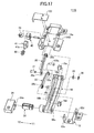
- Fig. 16 is an enlarged exploded perspective view of an opening/closing mechanism 111A provided at the Y1 direction side
- Fig. 17 is an enlarged exploded perspective view of an opening/closing mechanism 111B provided at the Y2 direction side.
- Fig. 18 shows the operation of the opening/closing mechanism 111A, where (A) shows the closed state and (B) shows the opened state.
- Fig. 19 shows the operation of the opening/closing mechanism 111B, where (A) shows the closed state and (B) shows the opened state.
- the opening/closing device 100 of the embodiment has substantially the same structure as the opening/closing device 10 explained with reference to Fig. 1 to Fig. 14 except that the base shaft 26 provided in the opening/closing device 10 is removed, and the hinge unit 30 is provided to each of the pair of the opening/closing mechanisms 111A and 111B.
- the same components corresponding to the components of the opening/closing device 10 shown in Fig. 1 to Fig. 14 are given the same reference numerals and explanations are not repeated. Further, for the opening/closing device 100 of the example, the structure different from that of the opening/closing device 10 is mainly explained.
- the electronic device 1 to which the opening/closing device 100 of the example is provided has a structure in which a liquid crystal display device 4A is provided to a second upper half body 3A and a liquid crystal display device 4B is provided to a first upper half body 2A. Further in this example as well, the pair of opening/closing mechanisms 111A and 111B are provided to be apart from each other in the Y1, Y2 direction.
- the opening/closing device 10 shown in Fig. 3 and the opening/closing device 100 shown in Fig. 15 are compared.
- the base shaft 26 is provided between the opening/closing mechanism 11A and the opening/closing mechanism 11B and the opening/closing mechanisms 11A and 11B are connected.
- the opening/closing mechanism 111A and the opening/closing mechanism 111B are independently provided and a base shaft is not provided between the opening/closing mechanisms 111A and 111B.
- the base shaft is not used as in this example, it is possible to provide more space for mounting components to be mounted on the first housing 2.
- the liquid crystal display device 4B when mounting the liquid crystal display device 4B on the first housing 2 as in this alternative example, as the liquid crystal display device 4B has a certain thickness, if the opening/closing device 10 including the base shaft 26 as shown in Fig. 3 is used, the liquid crystal display device cannot be provided at a position where the base shaft 26 is provided.
- the opening/closing device 100 of the example as the base shaft is not provided, components such as the liquid crystal display device or the like can be provided between the opening/closing mechanism 111A and the opening/closing mechanism 111B.
- the liquid crystal display device 4B when the liquid crystal display device 4B is mounted on the first housing 2, the liquid crystal display device 4B can be provided between the opening/closing mechanism 111A and the opening/closing mechanism 111B so that the liquid crystal display device 4A can be provided to be closer to an longitudinal end at the X1 direction of the first lower half body 2B.
- the liquid crystal display device 4B provided at the first upper half body 2A (first housing 2) can be provided extremely close to the liquid crystal display device 4A provided at the second upper half body 3A. Therefore, the two liquid crystal display devices 4A and 4B appear to be as if a single liquid crystal display panel so that the visibilities of the liquid crystal display devices 4A and 4B can be improved.
- the space corresponding to the provided components can be reduced, and thus, with this structure, the electronic device 1 can be made smaller.
- the hinge units 30 are provided for the opening/closing mechanisms 111A and 111B, respectively as the opening/closing mechanisms 111A and 111B are independently provided.
- the hinge units 30 are configured to have the same structure as that attached to the opening/closing mechanism 11B at the Y2 direction side of the opening/closing device 10.
- opening/closing mechanism 111A and the opening/closing mechanism 111B are independently provided, as shown in (A) and (B) of Fig. 18 , the opening/closing mechanism 111A is capable of rotating the hinge arm 18 in the direction shown by arrows P1 and P2 with respect to the fixed plate 16 regardless of the opening/closing mechanism 111B. Similarly, as shown in (A) and (B) of Fig. 19 , opening/closing mechanism 111B is capable of rotating the hinge arm 18 in the direction shown by the arrows P1 and P2 with respect to the fixed plate 12 regardless of the opening/closing mechanism 111A.
- the hinge unit 30 is provided only to one of the opening/closing mechanism, as the base shaft does not exist, when the open and close operation is performed for the second housing 3 with respect to the first housing 2, the running torque of the hinge unit 30 is applied only to the one of opening/closing mechanism.
- the running torque of the hinge unit 30 is applied to the first housing 2 and / or second housing 3 at a biased condition and there is a possibility that a stable open and close operation cannot be performed.
- the open and close operation is stably performed even when each of the opening/closing mechanisms 111A and 111B are independently provided.
- the hinge units 30 are provided outside the opening/closing mechanisms 111A and 111B. It means that the hinge unit 30 is provided at the Y1 direction side of the hinge arm 18 in the opening/closing mechanism 111A while the hinge unit 30 is provided at the Y2 direction side of the hinge arm 18 in the opening/closing mechanism 111B. With this structure, as the hinge units 30 are not provided between the pair of the opening/closing mechanisms 111A and 111B, the above described liquid crystal display device or components can be arbitrary placed.
- the difference between the opening/closing device 100 of the example and the opening/closing device 10 is that the movable plate 14 is composed by a combination of the inner plate 23 and the outer plate 24 in the opening/closing device 10, while the movable plates 114A and 114B are respectively integrally formed by pressing in this alternative example.
- a top plate 123 which covers the latch housing portion 24d is independently provided and the top plate 123 is fixed to the movable plate 114A or 114B by a screw, not shown in the drawings.
- the movable plates 114A and 114B are respectively integrally formed to improve assembling.
- first housing 3 second housing 10 100 opening/closing device 11A, 11B, 111A, 111B opening/closing mechanism 12, 16, 112, 116 fixed plate 14, 114A, 114B movable plate 16 fixed plate 18 hinge arm 20 slide arm 22 link arm 23 inner plate 24 outer plate 26 base shaft 30 hinge unit 31 head cam 32 slide cam 33a, 33b hinge spring 34 hinge housing 35 hinge plate 40 latch cam 40b cam groove 41 latch 41a protruding portion 42 latch spring 43 latch plate 44 slide arm shaft
Landscapes
- Engineering & Computer Science (AREA)
- Mechanical Engineering (AREA)
- Computer Hardware Design (AREA)
- Theoretical Computer Science (AREA)
- General Engineering & Computer Science (AREA)
- Signal Processing (AREA)
- Human Computer Interaction (AREA)
- Physics & Mathematics (AREA)
- General Physics & Mathematics (AREA)
- Pivots And Pivotal Connections (AREA)
- Telephone Set Structure (AREA)
- Transmission Devices (AREA)
Applications Claiming Priority (3)
| Application Number | Priority Date | Filing Date | Title |
|---|---|---|---|
| JP2010203383 | 2010-09-10 | ||
| JP2011094892A JP5161336B2 (ja) | 2010-09-10 | 2011-04-21 | 開閉装置 |
| PCT/JP2011/062129 WO2012032815A1 (fr) | 2010-09-10 | 2011-05-26 | Dispositif d'ouverture/fermeture |
Publications (3)
| Publication Number | Publication Date |
|---|---|
| EP2615331A1 true EP2615331A1 (fr) | 2013-07-17 |
| EP2615331A4 EP2615331A4 (fr) | 2016-04-27 |
| EP2615331B1 EP2615331B1 (fr) | 2017-10-04 |
Family
ID=45810422
Family Applications (1)
| Application Number | Title | Priority Date | Filing Date |
|---|---|---|---|
| EP11823294.1A Active EP2615331B1 (fr) | 2010-09-10 | 2011-05-26 | Dispositif d'ouverture/fermeture |
Country Status (6)
| Country | Link |
|---|---|
| US (1) | US9091105B2 (fr) |
| EP (1) | EP2615331B1 (fr) |
| JP (1) | JP5161336B2 (fr) |
| KR (1) | KR101487362B1 (fr) |
| CN (1) | CN103097770B (fr) |
| WO (1) | WO2012032815A1 (fr) |
Cited By (2)
| Publication number | Priority date | Publication date | Assignee | Title |
|---|---|---|---|---|
| EP3069208A4 (fr) * | 2013-11-15 | 2017-06-28 | Hewlett-Packard Development Company, L.P. | Bras de verrouillage pour dispositifs informatiques |
| WO2021145886A1 (fr) * | 2020-01-17 | 2021-07-22 | Microsoft Technology Licensing, Llc | Charnières de dispositif informatique |
Families Citing this family (17)
| Publication number | Priority date | Publication date | Assignee | Title |
|---|---|---|---|---|
| JP5415491B2 (ja) * | 2011-07-29 | 2014-02-12 | スガツネ工業株式会社 | 扉開閉装置ユニット及び扉開閉装置ユニットの取付け方法 |
| JP5415490B2 (ja) * | 2011-07-29 | 2014-02-12 | スガツネ工業株式会社 | 支持部材付き扉開閉装置及び扉開閉装置用の支持部材 |
| US20130104342A1 (en) * | 2011-10-27 | 2013-05-02 | Sony Mobile Communications Japan, Inc. | Mobile terminal |
| KR101285799B1 (ko) * | 2012-02-03 | 2013-07-23 | 권성태 | 이동 단말기용 힌지장치 |
| JP6101940B2 (ja) * | 2013-03-22 | 2017-03-29 | パナソニックIpマネジメント株式会社 | 電子機器、電子機器の組み立て方法 |
| US9353561B2 (en) * | 2013-06-10 | 2016-05-31 | Ronnie GAENZLE | 180 degree foldable locking hinge |
| CN103399620A (zh) * | 2013-08-12 | 2013-11-20 | 昆山万禾精密电子有限公司 | 多段式连动的铰链结构 |
| US9547341B2 (en) * | 2013-10-31 | 2017-01-17 | Sony Corporation | Information processing apparatus |
| TWI598022B (zh) * | 2015-11-16 | 2017-09-01 | Compal Electronics Inc | 電子裝置及其樞軸機構 |
| CN105559345B (zh) * | 2016-03-11 | 2018-10-02 | 成都紫瑞青云航空宇航技术有限公司 | 一种工作桌 |
| JP6688173B2 (ja) * | 2016-06-27 | 2020-04-28 | 日本電産サンキョー株式会社 | チルト駆動装置 |
| US10830525B2 (en) | 2016-10-17 | 2020-11-10 | Whirlpool Corporation | Hinge assembly |
| WO2019172883A1 (fr) * | 2018-03-06 | 2019-09-12 | Hewlett-Packard Development Company, L.P. | Ensembles charnière ayant des arbres de col composites |
| USD891426S1 (en) * | 2018-05-11 | 2020-07-28 | Fuvi Cognitive Network Corp. | Mobile device for visual and cognitive communication assistance |
| CN109339606B (zh) * | 2018-10-11 | 2020-09-11 | 赵崇良 | 自适应三轴铰链 |
| KR20210103873A (ko) * | 2020-02-14 | 2021-08-24 | 삼성전자주식회사 | 힌지 구조물 및 이를 포함하는 전자 장치 |
| CN115087255B (zh) * | 2022-07-30 | 2023-09-05 | 浙江尚昕能源科技有限公司 | 一种具有自防护功能的智能集中器 |
Family Cites Families (27)
| Publication number | Priority date | Publication date | Assignee | Title |
|---|---|---|---|---|
| US2001356A (en) * | 1934-04-04 | 1935-05-14 | Fred G Bates | Hinge |
| US2206708A (en) * | 1938-08-13 | 1940-07-02 | Walter W Stumpf | Hinge |
| DE2022515B1 (de) * | 1970-05-08 | 1971-11-11 | Kortenbach & Rauh Kg | Taschenschirm |
| US4475267A (en) * | 1982-04-02 | 1984-10-09 | Ampex Corporation | Shock absorbing bracket for a fallfront cabinet |
| JPH066539Y2 (ja) * | 1987-09-10 | 1994-02-16 | 株式会社ニフコ | 扉の開閉機構 |
| US5644469A (en) * | 1991-03-06 | 1997-07-01 | Canon Kabushiki Kaisha | Information processing apparatus support system with support arms which are capable of closing toward a keyboard unit or away from a keyboard unit |
| US6430038B1 (en) * | 2000-04-18 | 2002-08-06 | Hewlett-Packard Company | Computer with articulated mechanism |
| DE10223026C5 (de) * | 2002-05-22 | 2007-11-08 | Huwil-Werke Gmbh Möbelschloss- Und Beschlagfabriken | Deckelsteller |
| JP4357900B2 (ja) * | 2003-08-18 | 2009-11-04 | 加藤電機株式会社 | 小型情報端末用スライドヒンジ |
| JP2005303926A (ja) * | 2004-04-15 | 2005-10-27 | Sanyo Electric Co Ltd | 携帯電話機 |
| EP1703702B1 (fr) * | 2005-03-18 | 2008-04-30 | Sony Ericsson Mobile Communications AB | Equipement de communication portable et pliable comportant une charnière à double action |
| US7630193B2 (en) * | 2005-09-09 | 2009-12-08 | Microsoft Corporation | Multiple position computer display arm |
| KR100800677B1 (ko) * | 2006-09-07 | 2008-02-01 | 삼성전자주식회사 | 휴대 단말기의 다축 힌지 장치 및 이를 구비한 연결 부재 |
| US7748767B2 (en) * | 2006-11-01 | 2010-07-06 | Industrial Machining Services, Inc. | Hinge assembly |
| DE202007005957U1 (de) * | 2007-02-19 | 2008-06-26 | Liebherr-Hausgeräte Ochsenhausen GmbH | Kühl- und/oder Gefriergerät |
| JP5201568B2 (ja) * | 2007-04-18 | 2013-06-05 | Necカシオモバイルコミュニケーションズ株式会社 | 電子機器 |
| JP4772014B2 (ja) | 2007-08-30 | 2011-09-14 | ソニー エリクソン モバイル コミュニケーションズ, エービー | 携帯情報端末 |
| JP4729545B2 (ja) | 2007-09-13 | 2011-07-20 | 京セラ株式会社 | 携帯通信端末機 |
| JP2009218674A (ja) | 2008-03-07 | 2009-09-24 | Nec Corp | 携帯端末装置 |
| TWI362209B (en) * | 2008-10-08 | 2012-04-11 | Htc Corp | Portable electronic device |
| JP2010203383A (ja) | 2009-03-05 | 2010-09-16 | Hitachi Automotive Systems Ltd | 内燃機関の制御装置 |
| JP2011094892A (ja) | 2009-10-30 | 2011-05-12 | Panasonic Corp | レンジフード |
| CN102118938A (zh) * | 2009-12-31 | 2011-07-06 | 深圳富泰宏精密工业有限公司 | 电子装置 |
| US8468655B2 (en) * | 2010-04-22 | 2013-06-25 | Deere & Company | Hinge assembly for frame having two pivot axes |
| JP5944095B2 (ja) * | 2010-07-26 | 2016-07-05 | 三菱製鋼株式会社 | 開閉装置 |
| JP5611743B2 (ja) * | 2010-09-22 | 2014-10-22 | 三菱製鋼株式会社 | 開閉装置用カバー機構 |
| CN102619866A (zh) * | 2011-01-28 | 2012-08-01 | 鸿富锦精密工业(深圳)有限公司 | 铰链结构 |
-
2011
- 2011-04-21 JP JP2011094892A patent/JP5161336B2/ja active Active
- 2011-05-26 EP EP11823294.1A patent/EP2615331B1/fr active Active
- 2011-05-26 CN CN201180043023.5A patent/CN103097770B/zh active Active
- 2011-05-26 KR KR1020137005795A patent/KR101487362B1/ko active IP Right Grant
- 2011-05-26 US US13/821,689 patent/US9091105B2/en active Active
- 2011-05-26 WO PCT/JP2011/062129 patent/WO2012032815A1/fr active Application Filing
Cited By (4)
| Publication number | Priority date | Publication date | Assignee | Title |
|---|---|---|---|---|
| EP3069208A4 (fr) * | 2013-11-15 | 2017-06-28 | Hewlett-Packard Development Company, L.P. | Bras de verrouillage pour dispositifs informatiques |
| WO2021145886A1 (fr) * | 2020-01-17 | 2021-07-22 | Microsoft Technology Licensing, Llc | Charnières de dispositif informatique |
| CN114981752A (zh) * | 2020-01-17 | 2022-08-30 | 微软技术许可有限责任公司 | 计算设备铰链 |
| CN114981752B (zh) * | 2020-01-17 | 2024-07-16 | 微软技术许可有限责任公司 | 计算设备铰链 |
Also Published As
| Publication number | Publication date |
|---|---|
| EP2615331A4 (fr) | 2016-04-27 |
| JP2012077907A (ja) | 2012-04-19 |
| JP5161336B2 (ja) | 2013-03-13 |
| WO2012032815A1 (fr) | 2012-03-15 |
| CN103097770A (zh) | 2013-05-08 |
| KR20130048247A (ko) | 2013-05-09 |
| US9091105B2 (en) | 2015-07-28 |
| US20130160244A1 (en) | 2013-06-27 |
| KR101487362B1 (ko) | 2015-01-29 |
| CN103097770B (zh) | 2016-01-27 |
| EP2615331B1 (fr) | 2017-10-04 |
Similar Documents
| Publication | Publication Date | Title |
|---|---|---|
| EP2615331B1 (fr) | Dispositif d'ouverture/fermeture | |
| JP5599226B2 (ja) | 開閉装置 | |
| EP2621149B1 (fr) | Dispositif d'ouverture/fermeture | |
| RU2380850C2 (ru) | Портативное электронное устройство с поворотным шарнирным механизмом (варианты) | |
| EP2509287B1 (fr) | Mécanisme de coulissement-inclinaison | |
| WO2012014742A1 (fr) | Appareil d'ouverture/fermeture | |
| US8607415B2 (en) | Hinge apparatus for a foldable electronic device | |
| JP4754450B2 (ja) | 電子機器 | |
| JP6077269B2 (ja) | 開閉装置 | |
| WO2010140494A1 (fr) | Mécanisme d'inclinaison et dispositif coulissant | |
| US7096534B2 (en) | Hinge assembly with rotating mechanism | |
| JP5420486B2 (ja) | 開閉装置 | |
| EP2615317A1 (fr) | Mécanisme d'articulation | |
| JP3157566U (ja) | チルト機構 | |
| JP2009085229A (ja) | ヒンジ構造、及び電子機器 | |
| JP4899191B2 (ja) | 携帯電子機器 | |
| KR200338939Y1 (ko) | 휴대폰 커버의 이중 힌지장치 | |
| JP2007100897A (ja) | ヒンジ装置 |
Legal Events
| Date | Code | Title | Description |
|---|---|---|---|
| PUAI | Public reference made under article 153(3) epc to a published international application that has entered the european phase |
Free format text: ORIGINAL CODE: 0009012 |
|
| 17P | Request for examination filed |
Effective date: 20130307 |
|
| AK | Designated contracting states |
Kind code of ref document: A1 Designated state(s): AL AT BE BG CH CY CZ DE DK EE ES FI FR GB GR HR HU IE IS IT LI LT LU LV MC MK MT NL NO PL PT RO RS SE SI SK SM TR |
|
| DAX | Request for extension of the european patent (deleted) | ||
| RA4 | Supplementary search report drawn up and despatched (corrected) |
Effective date: 20160331 |
|
| RIC1 | Information provided on ipc code assigned before grant |
Ipc: H04M 1/02 20060101ALI20160323BHEP Ipc: E05D 11/10 20060101ALI20160323BHEP Ipc: F16H 21/10 20060101AFI20160323BHEP Ipc: E05D 3/06 20060101ALI20160323BHEP Ipc: G06F 1/16 20060101ALI20160323BHEP |
|
| GRAP | Despatch of communication of intention to grant a patent |
Free format text: ORIGINAL CODE: EPIDOSNIGR1 |
|
| INTG | Intention to grant announced |
Effective date: 20170213 |
|
| GRAS | Grant fee paid |
Free format text: ORIGINAL CODE: EPIDOSNIGR3 |
|
| GRAJ | Information related to disapproval of communication of intention to grant by the applicant or resumption of examination proceedings by the epo deleted |
Free format text: ORIGINAL CODE: EPIDOSDIGR1 |
|
| GRAL | Information related to payment of fee for publishing/printing deleted |
Free format text: ORIGINAL CODE: EPIDOSDIGR3 |
|
| RIN1 | Information on inventor provided before grant (corrected) |
Inventor name: SAYAMA, HIRONOBU |
|
| INTC | Intention to grant announced (deleted) | ||
| GRAA | (expected) grant |
Free format text: ORIGINAL CODE: 0009210 |
|
| GRAR | Information related to intention to grant a patent recorded |
Free format text: ORIGINAL CODE: EPIDOSNIGR71 |
|
| AK | Designated contracting states |
Kind code of ref document: B1 Designated state(s): AL AT BE BG CH CY CZ DE DK EE ES FI FR GB GR HR HU IE IS IT LI LT LU LV MC MK MT NL NO PL PT RO RS SE SI SK SM TR |
|
| INTG | Intention to grant announced |
Effective date: 20170829 |
|
| REG | Reference to a national code |
Ref country code: GB Ref legal event code: FG4D |
|
| REG | Reference to a national code |
Ref country code: CH Ref legal event code: EP |
|
| REG | Reference to a national code |
Ref country code: AT Ref legal event code: REF Ref document number: 934353 Country of ref document: AT Kind code of ref document: T Effective date: 20171015 |
|
| REG | Reference to a national code |
Ref country code: IE Ref legal event code: FG4D |
|
| REG | Reference to a national code |
Ref country code: DE Ref legal event code: R096 Ref document number: 602011042174 Country of ref document: DE |
|
| REG | Reference to a national code |
Ref country code: NL Ref legal event code: MP Effective date: 20171004 |
|
| REG | Reference to a national code |
Ref country code: LT Ref legal event code: MG4D |
|
| REG | Reference to a national code |
Ref country code: AT Ref legal event code: MK05 Ref document number: 934353 Country of ref document: AT Kind code of ref document: T Effective date: 20171004 |
|
| PG25 | Lapsed in a contracting state [announced via postgrant information from national office to epo] |
Ref country code: NL Free format text: LAPSE BECAUSE OF FAILURE TO SUBMIT A TRANSLATION OF THE DESCRIPTION OR TO PAY THE FEE WITHIN THE PRESCRIBED TIME-LIMIT Effective date: 20171004 |
|
| PG25 | Lapsed in a contracting state [announced via postgrant information from national office to epo] |
Ref country code: ES Free format text: LAPSE BECAUSE OF FAILURE TO SUBMIT A TRANSLATION OF THE DESCRIPTION OR TO PAY THE FEE WITHIN THE PRESCRIBED TIME-LIMIT Effective date: 20171004 Ref country code: FI Free format text: LAPSE BECAUSE OF FAILURE TO SUBMIT A TRANSLATION OF THE DESCRIPTION OR TO PAY THE FEE WITHIN THE PRESCRIBED TIME-LIMIT Effective date: 20171004 Ref country code: LT Free format text: LAPSE BECAUSE OF FAILURE TO SUBMIT A TRANSLATION OF THE DESCRIPTION OR TO PAY THE FEE WITHIN THE PRESCRIBED TIME-LIMIT Effective date: 20171004 Ref country code: SE Free format text: LAPSE BECAUSE OF FAILURE TO SUBMIT A TRANSLATION OF THE DESCRIPTION OR TO PAY THE FEE WITHIN THE PRESCRIBED TIME-LIMIT Effective date: 20171004 Ref country code: NO Free format text: LAPSE BECAUSE OF FAILURE TO SUBMIT A TRANSLATION OF THE DESCRIPTION OR TO PAY THE FEE WITHIN THE PRESCRIBED TIME-LIMIT Effective date: 20180104 |
|
| PG25 | Lapsed in a contracting state [announced via postgrant information from national office to epo] |
Ref country code: IS Free format text: LAPSE BECAUSE OF FAILURE TO SUBMIT A TRANSLATION OF THE DESCRIPTION OR TO PAY THE FEE WITHIN THE PRESCRIBED TIME-LIMIT Effective date: 20180204 Ref country code: RS Free format text: LAPSE BECAUSE OF FAILURE TO SUBMIT A TRANSLATION OF THE DESCRIPTION OR TO PAY THE FEE WITHIN THE PRESCRIBED TIME-LIMIT Effective date: 20171004 Ref country code: AT Free format text: LAPSE BECAUSE OF FAILURE TO SUBMIT A TRANSLATION OF THE DESCRIPTION OR TO PAY THE FEE WITHIN THE PRESCRIBED TIME-LIMIT Effective date: 20171004 Ref country code: HR Free format text: LAPSE BECAUSE OF FAILURE TO SUBMIT A TRANSLATION OF THE DESCRIPTION OR TO PAY THE FEE WITHIN THE PRESCRIBED TIME-LIMIT Effective date: 20171004 Ref country code: GR Free format text: LAPSE BECAUSE OF FAILURE TO SUBMIT A TRANSLATION OF THE DESCRIPTION OR TO PAY THE FEE WITHIN THE PRESCRIBED TIME-LIMIT Effective date: 20180105 Ref country code: LV Free format text: LAPSE BECAUSE OF FAILURE TO SUBMIT A TRANSLATION OF THE DESCRIPTION OR TO PAY THE FEE WITHIN THE PRESCRIBED TIME-LIMIT Effective date: 20171004 Ref country code: BG Free format text: LAPSE BECAUSE OF FAILURE TO SUBMIT A TRANSLATION OF THE DESCRIPTION OR TO PAY THE FEE WITHIN THE PRESCRIBED TIME-LIMIT Effective date: 20180104 |
|
| REG | Reference to a national code |
Ref country code: DE Ref legal event code: R097 Ref document number: 602011042174 Country of ref document: DE |
|
| PG25 | Lapsed in a contracting state [announced via postgrant information from national office to epo] |
Ref country code: SK Free format text: LAPSE BECAUSE OF FAILURE TO SUBMIT A TRANSLATION OF THE DESCRIPTION OR TO PAY THE FEE WITHIN THE PRESCRIBED TIME-LIMIT Effective date: 20171004 Ref country code: CZ Free format text: LAPSE BECAUSE OF FAILURE TO SUBMIT A TRANSLATION OF THE DESCRIPTION OR TO PAY THE FEE WITHIN THE PRESCRIBED TIME-LIMIT Effective date: 20171004 Ref country code: DK Free format text: LAPSE BECAUSE OF FAILURE TO SUBMIT A TRANSLATION OF THE DESCRIPTION OR TO PAY THE FEE WITHIN THE PRESCRIBED TIME-LIMIT Effective date: 20171004 Ref country code: EE Free format text: LAPSE BECAUSE OF FAILURE TO SUBMIT A TRANSLATION OF THE DESCRIPTION OR TO PAY THE FEE WITHIN THE PRESCRIBED TIME-LIMIT Effective date: 20171004 |
|
| PLBE | No opposition filed within time limit |
Free format text: ORIGINAL CODE: 0009261 |
|
| STAA | Information on the status of an ep patent application or granted ep patent |
Free format text: STATUS: NO OPPOSITION FILED WITHIN TIME LIMIT |
|
| PG25 | Lapsed in a contracting state [announced via postgrant information from national office to epo] |
Ref country code: SM Free format text: LAPSE BECAUSE OF FAILURE TO SUBMIT A TRANSLATION OF THE DESCRIPTION OR TO PAY THE FEE WITHIN THE PRESCRIBED TIME-LIMIT Effective date: 20171004 Ref country code: PL Free format text: LAPSE BECAUSE OF FAILURE TO SUBMIT A TRANSLATION OF THE DESCRIPTION OR TO PAY THE FEE WITHIN THE PRESCRIBED TIME-LIMIT Effective date: 20171004 Ref country code: IT Free format text: LAPSE BECAUSE OF FAILURE TO SUBMIT A TRANSLATION OF THE DESCRIPTION OR TO PAY THE FEE WITHIN THE PRESCRIBED TIME-LIMIT Effective date: 20171004 Ref country code: RO Free format text: LAPSE BECAUSE OF FAILURE TO SUBMIT A TRANSLATION OF THE DESCRIPTION OR TO PAY THE FEE WITHIN THE PRESCRIBED TIME-LIMIT Effective date: 20171004 |
|
| 26N | No opposition filed |
Effective date: 20180705 |
|
| PG25 | Lapsed in a contracting state [announced via postgrant information from national office to epo] |
Ref country code: SI Free format text: LAPSE BECAUSE OF FAILURE TO SUBMIT A TRANSLATION OF THE DESCRIPTION OR TO PAY THE FEE WITHIN THE PRESCRIBED TIME-LIMIT Effective date: 20171004 |
|
| REG | Reference to a national code |
Ref country code: CH Ref legal event code: PL |
|
| REG | Reference to a national code |
Ref country code: BE Ref legal event code: MM Effective date: 20180531 |
|
| PG25 | Lapsed in a contracting state [announced via postgrant information from national office to epo] |
Ref country code: MC Free format text: LAPSE BECAUSE OF FAILURE TO SUBMIT A TRANSLATION OF THE DESCRIPTION OR TO PAY THE FEE WITHIN THE PRESCRIBED TIME-LIMIT Effective date: 20171004 |
|
| REG | Reference to a national code |
Ref country code: IE Ref legal event code: MM4A |
|
| PG25 | Lapsed in a contracting state [announced via postgrant information from national office to epo] |
Ref country code: LI Free format text: LAPSE BECAUSE OF NON-PAYMENT OF DUE FEES Effective date: 20180531 Ref country code: CH Free format text: LAPSE BECAUSE OF NON-PAYMENT OF DUE FEES Effective date: 20180531 |
|
| PG25 | Lapsed in a contracting state [announced via postgrant information from national office to epo] |
Ref country code: LU Free format text: LAPSE BECAUSE OF NON-PAYMENT OF DUE FEES Effective date: 20180526 |
|
| PG25 | Lapsed in a contracting state [announced via postgrant information from national office to epo] |
Ref country code: FR Free format text: LAPSE BECAUSE OF NON-PAYMENT OF DUE FEES Effective date: 20180531 Ref country code: IE Free format text: LAPSE BECAUSE OF NON-PAYMENT OF DUE FEES Effective date: 20180526 |
|
| PG25 | Lapsed in a contracting state [announced via postgrant information from national office to epo] |
Ref country code: BE Free format text: LAPSE BECAUSE OF NON-PAYMENT OF DUE FEES Effective date: 20180531 |
|
| PG25 | Lapsed in a contracting state [announced via postgrant information from national office to epo] |
Ref country code: MT Free format text: LAPSE BECAUSE OF NON-PAYMENT OF DUE FEES Effective date: 20180526 |
|
| PG25 | Lapsed in a contracting state [announced via postgrant information from national office to epo] |
Ref country code: TR Free format text: LAPSE BECAUSE OF FAILURE TO SUBMIT A TRANSLATION OF THE DESCRIPTION OR TO PAY THE FEE WITHIN THE PRESCRIBED TIME-LIMIT Effective date: 20171004 |
|
| PG25 | Lapsed in a contracting state [announced via postgrant information from national office to epo] |
Ref country code: PT Free format text: LAPSE BECAUSE OF FAILURE TO SUBMIT A TRANSLATION OF THE DESCRIPTION OR TO PAY THE FEE WITHIN THE PRESCRIBED TIME-LIMIT Effective date: 20171004 Ref country code: HU Free format text: LAPSE BECAUSE OF FAILURE TO SUBMIT A TRANSLATION OF THE DESCRIPTION OR TO PAY THE FEE WITHIN THE PRESCRIBED TIME-LIMIT; INVALID AB INITIO Effective date: 20110526 |
|
| PG25 | Lapsed in a contracting state [announced via postgrant information from national office to epo] |
Ref country code: CY Free format text: LAPSE BECAUSE OF FAILURE TO SUBMIT A TRANSLATION OF THE DESCRIPTION OR TO PAY THE FEE WITHIN THE PRESCRIBED TIME-LIMIT Effective date: 20171004 Ref country code: MK Free format text: LAPSE BECAUSE OF NON-PAYMENT OF DUE FEES Effective date: 20171004 |
|
| PG25 | Lapsed in a contracting state [announced via postgrant information from national office to epo] |
Ref country code: AL Free format text: LAPSE BECAUSE OF FAILURE TO SUBMIT A TRANSLATION OF THE DESCRIPTION OR TO PAY THE FEE WITHIN THE PRESCRIBED TIME-LIMIT Effective date: 20171004 |
|
| PGFP | Annual fee paid to national office [announced via postgrant information from national office to epo] |
Ref country code: GB Payment date: 20240402 Year of fee payment: 14 |
|
| PGFP | Annual fee paid to national office [announced via postgrant information from national office to epo] |
Ref country code: DE Payment date: 20240328 Year of fee payment: 14 |