EP2614521B1 - Method of assembling a multichip module with underfilled semiconductor chip - Google Patents
Method of assembling a multichip module with underfilled semiconductor chip Download PDFInfo
- Publication number
- EP2614521B1 EP2614521B1 EP11757730.4A EP11757730A EP2614521B1 EP 2614521 B1 EP2614521 B1 EP 2614521B1 EP 11757730 A EP11757730 A EP 11757730A EP 2614521 B1 EP2614521 B1 EP 2614521B1
- Authority
- EP
- European Patent Office
- Prior art keywords
- semiconductor chip
- interposer
- sidewall
- underfill
- cover
- Prior art date
- Legal status (The legal status is an assumption and is not a legal conclusion. Google has not performed a legal analysis and makes no representation as to the accuracy of the status listed.)
- Active
Links
Images


Classifications
-
- H—ELECTRICITY
- H01—ELECTRIC ELEMENTS
- H01L—SEMICONDUCTOR DEVICES NOT COVERED BY CLASS H10
- H01L21/00—Processes or apparatus adapted for the manufacture or treatment of semiconductor or solid state devices or of parts thereof
- H01L21/02—Manufacture or treatment of semiconductor devices or of parts thereof
- H01L21/04—Manufacture or treatment of semiconductor devices or of parts thereof the devices having potential barriers, e.g. a PN junction, depletion layer or carrier concentration layer
- H01L21/50—Assembly of semiconductor devices using processes or apparatus not provided for in a single one of the groups H01L21/18 - H01L21/326 or H10D48/04 - H10D48/07 e.g. sealing of a cap to a base of a container
- H01L21/56—Encapsulations, e.g. encapsulation layers, coatings
- H01L21/563—Encapsulation of active face of flip-chip device, e.g. underfilling or underencapsulation of flip-chip, encapsulation preform on chip or mounting substrate
-
- H—ELECTRICITY
- H01—ELECTRIC ELEMENTS
- H01L—SEMICONDUCTOR DEVICES NOT COVERED BY CLASS H10
- H01L23/00—Details of semiconductor or other solid state devices
- H01L23/12—Mountings, e.g. non-detachable insulating substrates
-
- H—ELECTRICITY
- H01—ELECTRIC ELEMENTS
- H01L—SEMICONDUCTOR DEVICES NOT COVERED BY CLASS H10
- H01L23/00—Details of semiconductor or other solid state devices
- H01L23/28—Encapsulations, e.g. encapsulating layers, coatings, e.g. for protection
-
- H—ELECTRICITY
- H01—ELECTRIC ELEMENTS
- H01L—SEMICONDUCTOR DEVICES NOT COVERED BY CLASS H10
- H01L24/00—Arrangements for connecting or disconnecting semiconductor or solid-state bodies; Methods or apparatus related thereto
- H01L24/80—Methods for connecting semiconductor or other solid state bodies using means for bonding being attached to, or being formed on, the surface to be connected
- H01L24/83—Methods for connecting semiconductor or other solid state bodies using means for bonding being attached to, or being formed on, the surface to be connected using a layer connector
-
- H—ELECTRICITY
- H01—ELECTRIC ELEMENTS
- H01L—SEMICONDUCTOR DEVICES NOT COVERED BY CLASS H10
- H01L25/00—Assemblies consisting of a plurality of semiconductor or other solid state devices
- H01L25/03—Assemblies consisting of a plurality of semiconductor or other solid state devices all the devices being of a type provided for in a single subclass of subclasses H10B, H10D, H10F, H10H, H10K or H10N, e.g. assemblies of rectifier diodes
- H01L25/04—Assemblies consisting of a plurality of semiconductor or other solid state devices all the devices being of a type provided for in a single subclass of subclasses H10B, H10D, H10F, H10H, H10K or H10N, e.g. assemblies of rectifier diodes the devices not having separate containers
- H01L25/065—Assemblies consisting of a plurality of semiconductor or other solid state devices all the devices being of a type provided for in a single subclass of subclasses H10B, H10D, H10F, H10H, H10K or H10N, e.g. assemblies of rectifier diodes the devices not having separate containers the devices being of a type provided for in group H10D89/00
- H01L25/0655—Assemblies consisting of a plurality of semiconductor or other solid state devices all the devices being of a type provided for in a single subclass of subclasses H10B, H10D, H10F, H10H, H10K or H10N, e.g. assemblies of rectifier diodes the devices not having separate containers the devices being of a type provided for in group H10D89/00 the devices being arranged next to each other
-
- H—ELECTRICITY
- H01—ELECTRIC ELEMENTS
- H01L—SEMICONDUCTOR DEVICES NOT COVERED BY CLASS H10
- H01L25/00—Assemblies consisting of a plurality of semiconductor or other solid state devices
- H01L25/50—Multistep manufacturing processes of assemblies consisting of devices, the devices being individual devices of subclass H10D or integrated devices of class H10
-
- H—ELECTRICITY
- H01—ELECTRIC ELEMENTS
- H01L—SEMICONDUCTOR DEVICES NOT COVERED BY CLASS H10
- H01L2224/00—Indexing scheme for arrangements for connecting or disconnecting semiconductor or solid-state bodies and methods related thereto as covered by H01L24/00
- H01L2224/01—Means for bonding being attached to, or being formed on, the surface to be connected, e.g. chip-to-package, die-attach, "first-level" interconnects; Manufacturing methods related thereto
- H01L2224/10—Bump connectors; Manufacturing methods related thereto
- H01L2224/12—Structure, shape, material or disposition of the bump connectors prior to the connecting process
- H01L2224/13—Structure, shape, material or disposition of the bump connectors prior to the connecting process of an individual bump connector
- H01L2224/13001—Core members of the bump connector
- H01L2224/1302—Disposition
- H01L2224/13025—Disposition the bump connector being disposed on a via connection of the semiconductor or solid-state body
-
- H—ELECTRICITY
- H01—ELECTRIC ELEMENTS
- H01L—SEMICONDUCTOR DEVICES NOT COVERED BY CLASS H10
- H01L2224/00—Indexing scheme for arrangements for connecting or disconnecting semiconductor or solid-state bodies and methods related thereto as covered by H01L24/00
- H01L2224/01—Means for bonding being attached to, or being formed on, the surface to be connected, e.g. chip-to-package, die-attach, "first-level" interconnects; Manufacturing methods related thereto
- H01L2224/10—Bump connectors; Manufacturing methods related thereto
- H01L2224/15—Structure, shape, material or disposition of the bump connectors after the connecting process
- H01L2224/16—Structure, shape, material or disposition of the bump connectors after the connecting process of an individual bump connector
- H01L2224/161—Disposition
- H01L2224/16135—Disposition the bump connector connecting between different semiconductor or solid-state bodies, i.e. chip-to-chip
- H01L2224/16145—Disposition the bump connector connecting between different semiconductor or solid-state bodies, i.e. chip-to-chip the bodies being stacked
- H01L2224/16146—Disposition the bump connector connecting between different semiconductor or solid-state bodies, i.e. chip-to-chip the bodies being stacked the bump connector connecting to a via connection in the semiconductor or solid-state body
-
- H—ELECTRICITY
- H01—ELECTRIC ELEMENTS
- H01L—SEMICONDUCTOR DEVICES NOT COVERED BY CLASS H10
- H01L2224/00—Indexing scheme for arrangements for connecting or disconnecting semiconductor or solid-state bodies and methods related thereto as covered by H01L24/00
- H01L2224/01—Means for bonding being attached to, or being formed on, the surface to be connected, e.g. chip-to-package, die-attach, "first-level" interconnects; Manufacturing methods related thereto
- H01L2224/10—Bump connectors; Manufacturing methods related thereto
- H01L2224/15—Structure, shape, material or disposition of the bump connectors after the connecting process
- H01L2224/16—Structure, shape, material or disposition of the bump connectors after the connecting process of an individual bump connector
- H01L2224/161—Disposition
- H01L2224/16151—Disposition the bump connector connecting between a semiconductor or solid-state body and an item not being a semiconductor or solid-state body, e.g. chip-to-substrate, chip-to-passive
- H01L2224/16221—Disposition the bump connector connecting between a semiconductor or solid-state body and an item not being a semiconductor or solid-state body, e.g. chip-to-substrate, chip-to-passive the body and the item being stacked
- H01L2224/16225—Disposition the bump connector connecting between a semiconductor or solid-state body and an item not being a semiconductor or solid-state body, e.g. chip-to-substrate, chip-to-passive the body and the item being stacked the item being non-metallic, e.g. insulating substrate with or without metallisation
- H01L2224/16235—Disposition the bump connector connecting between a semiconductor or solid-state body and an item not being a semiconductor or solid-state body, e.g. chip-to-substrate, chip-to-passive the body and the item being stacked the item being non-metallic, e.g. insulating substrate with or without metallisation the bump connector connecting to a via metallisation of the item
-
- H—ELECTRICITY
- H01—ELECTRIC ELEMENTS
- H01L—SEMICONDUCTOR DEVICES NOT COVERED BY CLASS H10
- H01L2224/00—Indexing scheme for arrangements for connecting or disconnecting semiconductor or solid-state bodies and methods related thereto as covered by H01L24/00
- H01L2224/01—Means for bonding being attached to, or being formed on, the surface to be connected, e.g. chip-to-package, die-attach, "first-level" interconnects; Manufacturing methods related thereto
- H01L2224/10—Bump connectors; Manufacturing methods related thereto
- H01L2224/15—Structure, shape, material or disposition of the bump connectors after the connecting process
- H01L2224/17—Structure, shape, material or disposition of the bump connectors after the connecting process of a plurality of bump connectors
- H01L2224/171—Disposition
- H01L2224/1718—Disposition being disposed on at least two different sides of the body, e.g. dual array
- H01L2224/17181—On opposite sides of the body
-
- H—ELECTRICITY
- H01—ELECTRIC ELEMENTS
- H01L—SEMICONDUCTOR DEVICES NOT COVERED BY CLASS H10
- H01L2224/00—Indexing scheme for arrangements for connecting or disconnecting semiconductor or solid-state bodies and methods related thereto as covered by H01L24/00
- H01L2224/01—Means for bonding being attached to, or being formed on, the surface to be connected, e.g. chip-to-package, die-attach, "first-level" interconnects; Manufacturing methods related thereto
- H01L2224/26—Layer connectors, e.g. plate connectors, solder or adhesive layers; Manufacturing methods related thereto
- H01L2224/2612—Auxiliary members for layer connectors, e.g. spacers
- H01L2224/26122—Auxiliary members for layer connectors, e.g. spacers being formed on the semiconductor or solid-state body to be connected
- H01L2224/26145—Flow barriers
-
- H—ELECTRICITY
- H01—ELECTRIC ELEMENTS
- H01L—SEMICONDUCTOR DEVICES NOT COVERED BY CLASS H10
- H01L2224/00—Indexing scheme for arrangements for connecting or disconnecting semiconductor or solid-state bodies and methods related thereto as covered by H01L24/00
- H01L2224/01—Means for bonding being attached to, or being formed on, the surface to be connected, e.g. chip-to-package, die-attach, "first-level" interconnects; Manufacturing methods related thereto
- H01L2224/26—Layer connectors, e.g. plate connectors, solder or adhesive layers; Manufacturing methods related thereto
- H01L2224/2612—Auxiliary members for layer connectors, e.g. spacers
- H01L2224/26152—Auxiliary members for layer connectors, e.g. spacers being formed on an item to be connected not being a semiconductor or solid-state body
- H01L2224/26175—Flow barriers
-
- H—ELECTRICITY
- H01—ELECTRIC ELEMENTS
- H01L—SEMICONDUCTOR DEVICES NOT COVERED BY CLASS H10
- H01L2224/00—Indexing scheme for arrangements for connecting or disconnecting semiconductor or solid-state bodies and methods related thereto as covered by H01L24/00
- H01L2224/01—Means for bonding being attached to, or being formed on, the surface to be connected, e.g. chip-to-package, die-attach, "first-level" interconnects; Manufacturing methods related thereto
- H01L2224/26—Layer connectors, e.g. plate connectors, solder or adhesive layers; Manufacturing methods related thereto
- H01L2224/31—Structure, shape, material or disposition of the layer connectors after the connecting process
- H01L2224/32—Structure, shape, material or disposition of the layer connectors after the connecting process of an individual layer connector
- H01L2224/321—Disposition
- H01L2224/32135—Disposition the layer connector connecting between different semiconductor or solid-state bodies, i.e. chip-to-chip
- H01L2224/32145—Disposition the layer connector connecting between different semiconductor or solid-state bodies, i.e. chip-to-chip the bodies being stacked
-
- H—ELECTRICITY
- H01—ELECTRIC ELEMENTS
- H01L—SEMICONDUCTOR DEVICES NOT COVERED BY CLASS H10
- H01L2224/00—Indexing scheme for arrangements for connecting or disconnecting semiconductor or solid-state bodies and methods related thereto as covered by H01L24/00
- H01L2224/01—Means for bonding being attached to, or being formed on, the surface to be connected, e.g. chip-to-package, die-attach, "first-level" interconnects; Manufacturing methods related thereto
- H01L2224/26—Layer connectors, e.g. plate connectors, solder or adhesive layers; Manufacturing methods related thereto
- H01L2224/31—Structure, shape, material or disposition of the layer connectors after the connecting process
- H01L2224/32—Structure, shape, material or disposition of the layer connectors after the connecting process of an individual layer connector
- H01L2224/321—Disposition
- H01L2224/32151—Disposition the layer connector connecting between a semiconductor or solid-state body and an item not being a semiconductor or solid-state body, e.g. chip-to-substrate, chip-to-passive
- H01L2224/32221—Disposition the layer connector connecting between a semiconductor or solid-state body and an item not being a semiconductor or solid-state body, e.g. chip-to-substrate, chip-to-passive the body and the item being stacked
- H01L2224/32225—Disposition the layer connector connecting between a semiconductor or solid-state body and an item not being a semiconductor or solid-state body, e.g. chip-to-substrate, chip-to-passive the body and the item being stacked the item being non-metallic, e.g. insulating substrate with or without metallisation
-
- H—ELECTRICITY
- H01—ELECTRIC ELEMENTS
- H01L—SEMICONDUCTOR DEVICES NOT COVERED BY CLASS H10
- H01L2224/00—Indexing scheme for arrangements for connecting or disconnecting semiconductor or solid-state bodies and methods related thereto as covered by H01L24/00
- H01L2224/73—Means for bonding being of different types provided for in two or more of groups H01L2224/10, H01L2224/18, H01L2224/26, H01L2224/34, H01L2224/42, H01L2224/50, H01L2224/63, H01L2224/71
- H01L2224/732—Location after the connecting process
- H01L2224/73201—Location after the connecting process on the same surface
- H01L2224/73203—Bump and layer connectors
- H01L2224/73204—Bump and layer connectors the bump connector being embedded into the layer connector
-
- H—ELECTRICITY
- H01—ELECTRIC ELEMENTS
- H01L—SEMICONDUCTOR DEVICES NOT COVERED BY CLASS H10
- H01L2224/00—Indexing scheme for arrangements for connecting or disconnecting semiconductor or solid-state bodies and methods related thereto as covered by H01L24/00
- H01L2224/80—Methods for connecting semiconductor or other solid state bodies using means for bonding being attached to, or being formed on, the surface to be connected
- H01L2224/81—Methods for connecting semiconductor or other solid state bodies using means for bonding being attached to, or being formed on, the surface to be connected using a bump connector
- H01L2224/818—Bonding techniques
- H01L2224/81801—Soldering or alloying
- H01L2224/81815—Reflow soldering
-
- H—ELECTRICITY
- H01—ELECTRIC ELEMENTS
- H01L—SEMICONDUCTOR DEVICES NOT COVERED BY CLASS H10
- H01L2224/00—Indexing scheme for arrangements for connecting or disconnecting semiconductor or solid-state bodies and methods related thereto as covered by H01L24/00
- H01L2224/91—Methods for connecting semiconductor or solid state bodies including different methods provided for in two or more of groups H01L2224/80 - H01L2224/90
- H01L2224/92—Specific sequence of method steps
- H01L2224/921—Connecting a surface with connectors of different types
- H01L2224/9212—Sequential connecting processes
- H01L2224/92122—Sequential connecting processes the first connecting process involving a bump connector
- H01L2224/92125—Sequential connecting processes the first connecting process involving a bump connector the second connecting process involving a layer connector
-
- H—ELECTRICITY
- H01—ELECTRIC ELEMENTS
- H01L—SEMICONDUCTOR DEVICES NOT COVERED BY CLASS H10
- H01L2224/00—Indexing scheme for arrangements for connecting or disconnecting semiconductor or solid-state bodies and methods related thereto as covered by H01L24/00
- H01L2224/93—Batch processes
- H01L2224/94—Batch processes at wafer-level, i.e. with connecting carried out on a wafer comprising a plurality of undiced individual devices
-
- H—ELECTRICITY
- H01—ELECTRIC ELEMENTS
- H01L—SEMICONDUCTOR DEVICES NOT COVERED BY CLASS H10
- H01L24/00—Arrangements for connecting or disconnecting semiconductor or solid-state bodies; Methods or apparatus related thereto
- H01L24/01—Means for bonding being attached to, or being formed on, the surface to be connected, e.g. chip-to-package, die-attach, "first-level" interconnects; Manufacturing methods related thereto
- H01L24/10—Bump connectors ; Manufacturing methods related thereto
- H01L24/12—Structure, shape, material or disposition of the bump connectors prior to the connecting process
- H01L24/13—Structure, shape, material or disposition of the bump connectors prior to the connecting process of an individual bump connector
-
- H—ELECTRICITY
- H01—ELECTRIC ELEMENTS
- H01L—SEMICONDUCTOR DEVICES NOT COVERED BY CLASS H10
- H01L24/00—Arrangements for connecting or disconnecting semiconductor or solid-state bodies; Methods or apparatus related thereto
- H01L24/01—Means for bonding being attached to, or being formed on, the surface to be connected, e.g. chip-to-package, die-attach, "first-level" interconnects; Manufacturing methods related thereto
- H01L24/10—Bump connectors ; Manufacturing methods related thereto
- H01L24/15—Structure, shape, material or disposition of the bump connectors after the connecting process
- H01L24/16—Structure, shape, material or disposition of the bump connectors after the connecting process of an individual bump connector
-
- H—ELECTRICITY
- H01—ELECTRIC ELEMENTS
- H01L—SEMICONDUCTOR DEVICES NOT COVERED BY CLASS H10
- H01L24/00—Arrangements for connecting or disconnecting semiconductor or solid-state bodies; Methods or apparatus related thereto
- H01L24/01—Means for bonding being attached to, or being formed on, the surface to be connected, e.g. chip-to-package, die-attach, "first-level" interconnects; Manufacturing methods related thereto
- H01L24/10—Bump connectors ; Manufacturing methods related thereto
- H01L24/15—Structure, shape, material or disposition of the bump connectors after the connecting process
- H01L24/17—Structure, shape, material or disposition of the bump connectors after the connecting process of a plurality of bump connectors
-
- H—ELECTRICITY
- H01—ELECTRIC ELEMENTS
- H01L—SEMICONDUCTOR DEVICES NOT COVERED BY CLASS H10
- H01L24/00—Arrangements for connecting or disconnecting semiconductor or solid-state bodies; Methods or apparatus related thereto
- H01L24/01—Means for bonding being attached to, or being formed on, the surface to be connected, e.g. chip-to-package, die-attach, "first-level" interconnects; Manufacturing methods related thereto
- H01L24/26—Layer connectors, e.g. plate connectors, solder or adhesive layers; Manufacturing methods related thereto
- H01L24/31—Structure, shape, material or disposition of the layer connectors after the connecting process
- H01L24/32—Structure, shape, material or disposition of the layer connectors after the connecting process of an individual layer connector
-
- H—ELECTRICITY
- H01—ELECTRIC ELEMENTS
- H01L—SEMICONDUCTOR DEVICES NOT COVERED BY CLASS H10
- H01L24/00—Arrangements for connecting or disconnecting semiconductor or solid-state bodies; Methods or apparatus related thereto
- H01L24/73—Means for bonding being of different types provided for in two or more of groups H01L24/10, H01L24/18, H01L24/26, H01L24/34, H01L24/42, H01L24/50, H01L24/63, H01L24/71
-
- H—ELECTRICITY
- H01—ELECTRIC ELEMENTS
- H01L—SEMICONDUCTOR DEVICES NOT COVERED BY CLASS H10
- H01L24/00—Arrangements for connecting or disconnecting semiconductor or solid-state bodies; Methods or apparatus related thereto
- H01L24/80—Methods for connecting semiconductor or other solid state bodies using means for bonding being attached to, or being formed on, the surface to be connected
- H01L24/81—Methods for connecting semiconductor or other solid state bodies using means for bonding being attached to, or being formed on, the surface to be connected using a bump connector
-
- H—ELECTRICITY
- H01—ELECTRIC ELEMENTS
- H01L—SEMICONDUCTOR DEVICES NOT COVERED BY CLASS H10
- H01L24/00—Arrangements for connecting or disconnecting semiconductor or solid-state bodies; Methods or apparatus related thereto
- H01L24/91—Methods for connecting semiconductor or solid state bodies including different methods provided for in two or more of groups H01L24/80 - H01L24/90
- H01L24/92—Specific sequence of method steps
-
- H—ELECTRICITY
- H01—ELECTRIC ELEMENTS
- H01L—SEMICONDUCTOR DEVICES NOT COVERED BY CLASS H10
- H01L2924/00—Indexing scheme for arrangements or methods for connecting or disconnecting semiconductor or solid-state bodies as covered by H01L24/00
- H01L2924/10—Details of semiconductor or other solid state devices to be connected
- H01L2924/102—Material of the semiconductor or solid state bodies
- H01L2924/1025—Semiconducting materials
- H01L2924/10251—Elemental semiconductors, i.e. Group IV
- H01L2924/10252—Germanium [Ge]
-
- H—ELECTRICITY
- H01—ELECTRIC ELEMENTS
- H01L—SEMICONDUCTOR DEVICES NOT COVERED BY CLASS H10
- H01L2924/00—Indexing scheme for arrangements or methods for connecting or disconnecting semiconductor or solid-state bodies as covered by H01L24/00
- H01L2924/10—Details of semiconductor or other solid state devices to be connected
- H01L2924/102—Material of the semiconductor or solid state bodies
- H01L2924/1025—Semiconducting materials
- H01L2924/10251—Elemental semiconductors, i.e. Group IV
- H01L2924/10253—Silicon [Si]
-
- H—ELECTRICITY
- H01—ELECTRIC ELEMENTS
- H01L—SEMICONDUCTOR DEVICES NOT COVERED BY CLASS H10
- H01L2924/00—Indexing scheme for arrangements or methods for connecting or disconnecting semiconductor or solid-state bodies as covered by H01L24/00
- H01L2924/10—Details of semiconductor or other solid state devices to be connected
- H01L2924/11—Device type
- H01L2924/12—Passive devices, e.g. 2 terminal devices
- H01L2924/1204—Optical Diode
- H01L2924/12042—LASER
-
- H—ELECTRICITY
- H01—ELECTRIC ELEMENTS
- H01L—SEMICONDUCTOR DEVICES NOT COVERED BY CLASS H10
- H01L2924/00—Indexing scheme for arrangements or methods for connecting or disconnecting semiconductor or solid-state bodies as covered by H01L24/00
- H01L2924/10—Details of semiconductor or other solid state devices to be connected
- H01L2924/11—Device type
- H01L2924/14—Integrated circuits
- H01L2924/143—Digital devices
- H01L2924/1431—Logic devices
-
- H—ELECTRICITY
- H01—ELECTRIC ELEMENTS
- H01L—SEMICONDUCTOR DEVICES NOT COVERED BY CLASS H10
- H01L2924/00—Indexing scheme for arrangements or methods for connecting or disconnecting semiconductor or solid-state bodies as covered by H01L24/00
- H01L2924/10—Details of semiconductor or other solid state devices to be connected
- H01L2924/11—Device type
- H01L2924/14—Integrated circuits
- H01L2924/143—Digital devices
- H01L2924/1433—Application-specific integrated circuit [ASIC]
-
- H—ELECTRICITY
- H01—ELECTRIC ELEMENTS
- H01L—SEMICONDUCTOR DEVICES NOT COVERED BY CLASS H10
- H01L2924/00—Indexing scheme for arrangements or methods for connecting or disconnecting semiconductor or solid-state bodies as covered by H01L24/00
- H01L2924/10—Details of semiconductor or other solid state devices to be connected
- H01L2924/11—Device type
- H01L2924/14—Integrated circuits
- H01L2924/143—Digital devices
- H01L2924/1434—Memory
-
- H—ELECTRICITY
- H01—ELECTRIC ELEMENTS
- H01L—SEMICONDUCTOR DEVICES NOT COVERED BY CLASS H10
- H01L2924/00—Indexing scheme for arrangements or methods for connecting or disconnecting semiconductor or solid-state bodies as covered by H01L24/00
- H01L2924/15—Details of package parts other than the semiconductor or other solid state devices to be connected
- H01L2924/151—Die mounting substrate
- H01L2924/1515—Shape
- H01L2924/15158—Shape the die mounting substrate being other than a cuboid
- H01L2924/15159—Side view
-
- H—ELECTRICITY
- H01—ELECTRIC ELEMENTS
- H01L—SEMICONDUCTOR DEVICES NOT COVERED BY CLASS H10
- H01L2924/00—Indexing scheme for arrangements or methods for connecting or disconnecting semiconductor or solid-state bodies as covered by H01L24/00
- H01L2924/15—Details of package parts other than the semiconductor or other solid state devices to be connected
- H01L2924/151—Die mounting substrate
- H01L2924/153—Connection portion
- H01L2924/1531—Connection portion the connection portion being formed only on the surface of the substrate opposite to the die mounting surface
- H01L2924/15311—Connection portion the connection portion being formed only on the surface of the substrate opposite to the die mounting surface being a ball array, e.g. BGA
Definitions
- This invention relates generally to semiconductor processing, and more particularly to multi-chip mounting structures and underfills and methods of assembling the same.
- a conventional type of multi-chip module includes two semiconductor chips mounted side-by-side on a carrier substrate or interposer.
- the semiconductor chips are flip-chip mounted to the interposer and interconnected thereto by respective pluralities of solder joints.
- the interposer is provided with plural electrical pathways to provide input/output pathways for the semiconductor chips both for interchip power, ground and signal propagation as well as input/output from the interposer itself.
- the semiconductor chips include respective underfill material layers to lessen the effects of differential thermal expansion due to differences in the coefficients of thermal expansion of the chips, the interposer and the solderjoints.
- a conventional method for fabricating the aforementioned conventional multi-chip module includes flip-chip mounting the first of the two semiconductor chips on the interposer and dispensing an underfill between the first mounted chip and the interposer.
- the underfill migrates laterally between the chip and the interposer and, upon thermal cure, produces a fillet that extends beyond the periphery of the semiconductor chip.
- the second semiconductor chip is flip-chip mounted to the interposer and a second underfill is positioned between the second mounted semiconductor chip and the interposer.
- the second underfill produces another fillet that extends beyond the periphery of the second semiconductor chip and typically abuts against the fillet of the first underfill of the first semiconductor chip.
- a conventional set of design rules for manufacturing the aforementioned conventional multi-chip module has to account for the respective widths of the underfill material layer fillets.
- the fillets themselves present a constraint on the minimum permissible spacing between the two adjacent semiconductor chips.
- a constraint on the miniaturization of conductor strnctures, such as the conductive pathways between the semiconductor chips of the module presents a limit on the amount of reduction in signal latency and perhaps power consumption due to resistive losses and other issues associated with line length.
- the present invention is directed to overcoming or reducing the effects of one or more of the foregoing disadvantages.
- JP2009 158623 and JP-A-10074868 provide for a method of manufacturing a semiconductor apparatus removing a resin dam for damming the outflow of an underfill resin.
- JP 2000 357768 discloses a method for obtaining a semiconductor device which prevents adjacent semiconductor chips from being connected to each other by a resin.
- US 2004/124513 discloses a high density multichip module package which integrates active an passive devices.
- the present invention provides a method of manufacturing as claimed in claim 1.
- Various multi-chip stack arrangements are disclosed. Two or more semiconductor chips are stacked on a substrate, which may be a semiconductor chip, an interposer, a carrier substrate or something else. Prior to mounting the second semiconductor chip (and perhaps others), a removable cover is positioned on the interposer near a sidewall of the first mounted chip to act as a barrier to lateral flow of an underfill placed between the first mounted chip and the interposer. By constraining underfill fillet formation, chip-to-chip spacing can be reduced with attendant improvements in latency. Additional details will now be described.
- FIG. 1 a sectional view of an exemplary conventional semiconductor chip device 10 that includes two semiconductor chips 15 and 20 mounted on a substrate 25, which in the illustrative example is an interposer, but which could be a carrier substrate or some other type of substrate.
- a plurality of thru-silicon vias (TSV) 30 are formed in the interposer 25 and may be connected to some form of input/output structure to enable the interposer 25 to electrically interface with some of the device (not shown).
- TSV thru-silicon vias
- the semiconductor chip 15 may be electrically connected to some of the TSVs 30 by way of solder bumps 35 and the semiconductor chip 20 may be connected to others of the TSVs 30 by way of another group of solder bumps 40.
- the interposer 25 is sometimes constructed of silicon. To lessen the effects of differential CTE between the semiconductor chip 15 and the interposer 25, an underfill material 45 is introduced between the semiconductor chip 15 and the interposer 25. Typically, the dispensing of the underfill 45 is by way of capillary flow which leaves a fillet 50 that has some width X 1 .
- the space between the semiconductor chip 20 and the interposer 25 is similarly filled with an underfill 55 that has a fillet 60 with a lateral dimension X 2 .
- the semiconductor chip 15 and the underfill 45 are typically positioned on the interposer 25 first and then one or more electrical tests are performed to verify the operation of both the semicondcutor chip 15 and the interposer 25. Thereafter, the semiconductor chip 20 and the underfill 55 are positioned on the interposer 25 and further electrical testing is performed.
- the lateral dimensions X 1 and X 2 of the fillets 50 and 60 constrain the minimum spacing X 3 between the semiconductor chips 15 and 20.
- electrical routing either in or within the interposer 25 to accommodate power, ground and signal between the chips 15 and 20 and the interposer 25 may be constrained.
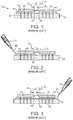
- FIGS. 2 and 3 are successive sectional views of the interposer 25 and the semiconductor chips 15 and 20 undergoing processing steps.
- the semiconductor chip 15 has been previously flip-chip mounted to the interposer 25.
- the underfill 45 is dispensed by some suitable applicator 60 and capillary action used to disperse the underfill 45 into the gap 65 between the semiconductor chip 15 and the interposer 25.
- the underfill 45 is then subjected to a thermal cure which establishes the final width X 1 of the fillet 50.
- the semiconductor chip 20 may also be flip-chip mounted to the interposer 25. If so, at this stage or at a later stage, the semiconductor chip 20 is mounted with the planned minimum spacing X 3 from the semiconductor chip 15.
- the underfill 55 is dispensed in the gap 75 between the semiconductor chip 20 and the interposer 25 by way of the applicator 70.
- the fillet 60 will set up with the lateral dimension X 2 .
- the minimum spacing X 3 is designed to accommodate the anticipated widths X 1 and X 2 of the respective fillets 50 and 60.
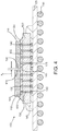
- An exemplary semiconductor chip device 100 may be produced in accordance with an embodiment of the invention provides for a much smaller minimum spacing between two semiconductor chips on an interposer may be understood by referring now to FIG. 4 , which is a sectional view.
- the semiconductor chip device 100 includes semiconductor chips 110 and 115 mounted on an interposer 120.
- the interposer 120 may, in turn, be mounted to a circuit board 125, which may be a carrier substrate or circuit board of one sort or another.
- the mounting structures and techniques described herein are not limited to any particular types of semiconductor devices.
- the semiconductor chips 110 and 115 may be any of a myriad of different types of circuit devices used in electronics, such as, for example, microprocessors, graphics processors, combined microprocessor/graphics processors, application specific integrated circuits, memory devices, active optical devices, such as lasers, or the like, and may be single or multi-core or even stacked laterally with additional dice. Furthermore, one or both of the semiconductor chips 110 and 115 could be configured as an interposer with or without some logic circuits. Thus the term "chip” includes an interposer and vice versa.
- the semiconductor chips 15 and 155 may be constructed of bulk semiconductor, such as silicon or germanium, or semiconductor on insulator materials, such as silicon-on-insulator materials, or even other types of materials.
- the interposer 120 may take on a variety of configurations. If typically configured, the interposer 120 may consist of a substrate of a material(s) with a coefficient of thermal expansion (CTE) that is near the CTE of the semiconductor chips 110 and 115 and that includes plural internal conductor traces and vias for electrical routing.
- CTE coefficient of thermal expansion
- Various semiconductor materials may be used, such as silicon, germanium or the like, or even insulator materials, such as silicon dioxide, tetra-ethyl-ortho-silicate or the like.. Silicon has the advantage of a favorable CTE and the widespread availability of mature fabrication processes.
- the interposer could also be fabricated as an integrated circuit like the other semiconductor chips 110 and 115.
- the interposer 120 could be fabricated on a wafer level or chip level process. Indeed, one or the other of semiconductor chips 110 and 115 could be fabricated on either a wafer or chip level basis, and then singulated and mounted to an interposer 30 that has not been singulated from a wafer.
- the interposer 120 may be provided with plural TSVs 130.
- the TSVs 130 may be accompanied by multilevel metallization structures that consist of plural lines and traces and interconnecting vias as desired (not visible). Indeed, the electrical interface structures associated with the interposer 120 may take on a great variety of configurations.
- the semiconductor chip 110 may be connected to the TSVs 130 by way of plural interconnect structures 135, which may be conductive bumps, conductive pillars, or the like.
- the semiconductor chip 115 may be similarly connected to some of the TSVs 130 by way of plural interconnect structures 140 which may be conductive bumps, conductive pillars, or the like.
- the interposer 120 may be provided with plural input/output structures 143.
- the input/output structures 143 may be conductive bumps, conductive pillars, or the like.
- an underfill material 145 may be dispensed between the interposer 120 and the circuit board 125.
- the circuit board 125 may be provided with plural input/output structures to provide electrical interfaces with another circuit device such as another circuit board or other device (not shown).
- the input/output devices in this illustrative example consist of a ball grid array of solder balls 150.
- any other type of interconnect structures such as a pin grid array, a land grid array or any other type of interface structure may be used.
- the circuit board 125 may take on a variety of configurations. Examples include a semiconductor chip package substrate, a circuit card, or virtually any other type of printed circuit board. Although a monolithic structure could be used for the circuit board 125, a more typical configuration will utilize a buildup design.
- the circuit board 125 may consist of a central core upon which one or more buildup layers are formed and below which an additional one or more buildup layers are formed.
- the core itself may consist of a stack of one or more layers. If implemented as a semiconductor chip package substrate, the number of layers in the circuit board 125 can vary from four to sixteen or more, although less than four may be used. So-called “coreless" designs may be used as well.
- the layers of the circuit board 125 may consist of an insulating material, such as various well-known epoxies, interspersed with metal interconnects. A multi-layer configuration other than buildup could be used.
- the circuit board 125 may be composed of well-known ceramics or other materials suitable for package substrates or other printed circuit boards.
- the circuit board 125 is provided with a number of conductor traces and vias and other structures (not visible) in order to provide power, ground and signals transfers between the semiconductor chips 110 and 115 and another device, such as another circuit board for example.
- an underfill material 155 is dispensed in a gap 160 between the semiconductor chip 110 and the interposer 120.
- the underfill 155 includes only a relatively narrow fillet 165 proximate the sidewall 170 of the semiconductor chip 110.
- the fillet 165 may have a relatively vertical sidewall 175.
- the semiconductor chip 115 is similarly provided with an underfill 180 dispensed in the gap 185 between the chip 115 and the interposer 120. Due to the exemplary technique for positioning the underfills 155 and 180, the underfill 155 includes only the relatively narrow fillet 165 and the underfill 180 includes virtually no fillet proximate the sidewall 190 of the semiconductor chip 115.
- the underfills 145, 155 and 180 may be composed of well-known epoxy materials, such as epoxy resin with or without silica fillers and phenol resins or the like. Two examples are types 8437-2 and 2BD available from Namics.
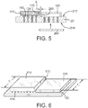
- FIG. 5 depicts the interposer 120 after the semiconductor chip 110 has been mounted thereto and electrically interfaced therewith by way of the interconnect structures 135.
- the TSVs 130 may have already been established in the interposer 125 using well-known techniques.
- the mounting of the semiconductor chip 110 to the interposer 120 may include a reflow process to temporarily liquify any solder associated with the interconnect structures 135.
- the gap 160 between the semiconductor chip 110 and the interposer 120 is open.
- a cover 195 is removably positioned on the interposer 120 with a lateral set off from the sidewall 170 of the semiconductor chip 110 that matches the preferred spacing X 4 between the semiconductor chips 110 and 115 as shown in FIG. 4 .
- the cover 195 may be a simple box as depicted in FIG. 5 or any of a myriad of other arrangements as illustrated in subsequent figures.
- An important feature of the cover 195 is a sidewall 200 which faces toward the sidewall 170 of the semiconductor chip 110.
- the sidewall 200 acts as a barrier against the lateral migration of underfill away from the sidewall 170 of the chip 110.
- a variety of techniques may be used to hold the cover 195 in position during a subsequent application of the underfill material 155 depicted in FIG. 4 .
- the cover 195 may be merely held in place by its own weight.
- the cover 195 may be constructed of a ferromagnetic material or materials and then held in position by way of a magnet 205, which may be a permanent magnet or electromagnet.
- the magnet 205 may be positioned against the lower surface 210 of the interposer 120 and used to pull the cover 195 toward the upper surface 215 of the interposer 120.
- the underfill 155 may have significant adhesive properties.
- the cover 195 may be coated with a suitable material, such as Teflon, to ease post underfill removal.
- FIG. 6 is a pictorial view of the interposer 120, the semiconductor chip 110 and the cover 195. Note that a few of the interconnect structures 135 are visible.
- the semiconductor chip 110 may have a dimension Y 1 , which may be a length or a width. It is desirable for the cover 195 to have a corresponding dimension Y 2 , which should be approximately equal to or perhaps greater than the lateral dimension Y 1 of the semiconductor chip 110. This selection of the dimension Y 2 will prevent the unwanted lateral migration of any underfill away from the sidewall 170 of the semiconductor chip 110 during dispensing and subsequent thermal curing.
- FIG. 7 is a sectional view like FIG. 5 .
- the underfill 155 may be dispensed by way of a suitable applicator 220.
- the underfill 155 proceeds into the gap 160 by way of capillary action, but is constrained from movement beyond the sidewall 170 of the semiconductor chip 110 by way of the wall 200 of the cover 195.
- the underfill 155 will form with the fillet 165 of the desired lateral dimension X 4 and with the optional vertical sidewall 175.
- a suitable curing process may be performed on the underfill 155 so that the fillet 165 sets up.
- the sidewall 175 is optionally substantially parallel to the sidewall 170 of the semiconductor chip 110.
- connection 235 is a schematic representation and may be a probe pin, plural probe pins, a socket connection on a circuit board or virtually any other type of electrical interface.
- the test device 230 may be a computer, an application specific integrated circuit, or virtually any other diagnostic device used to test integrated circuits.
- a goal of the testing is to establish at this stage of processing whether or not the semiconductor chip 110 and/or the interposer 120 are defective. If the semiconductor chip 110 and/or the interposer 120 have defects at this stage, then either the semiconductor chip 110 and/or the interposer 120 may be reworked or scrapped as necessary.
- the semiconductor chip 115 may be flip-chip mounted to the interposer 120 so that the sidewall 190 abuts the fillet 165 of the underfill 155. This establishes the aforementioned desired lateral dimension X 4 between the semiconductor chips 110 and 115.
- the interconnect structures 140 may be subjected to a reflow process if necessary depending upon the composition thereof.
- the underfill 180 may be dispensed in the gap 185 between the semiconductor chip 115 and the interposer 120 by way of the applicator 220. The underfill 180 proceeds along the gap 185 by way of capillary action until it abuts the fillet 165 of the underfill 155.
- the interposer 120 and the semiconductor chips 110 and 115 may again be connected to the test device 230 depicted in FIG. 8 and electrical tests performed to establish the suitability of the semiconductor chip 115.
- the desired short spacing X 4 established between the semiconductor chips 110 and 115, but additionally the reliability of the semiconductor chip 110 and the interposer 120 may be established prior to performing the steps and expending the materials associated with mounting the semiconductor chip 115.
- a cover 195' may be configured as a simple wall that has a lateral dimension Y 2 that matches or exceeds the lateral dimension Y 1 of the semiconductor chip 110.
- the cover 195' may be secured to the interposer 120 by way of any of the techniques disclosed therein. Again, the cover 195' will be offset laterally from the sidewall 170 of the semiconductor chip 110 by way of the desired spacing X 4 .
- FIG. 12 is a pictorial view like FIG. 11 .
- the semiconductor chip 110 is mounted to the interposer as described elsewhere herein.
- the cover 195" in this illustrative embodiment is configured as a box-like structure with an open end 250. This type of arrangement may be desirable where, for example, there are surface mounted structures (not shown) in the vicinity of the region 255 of the interposer 120 that must be accounted for spatially.
- the cover 195" has a lateral dimension that matches or exceeds the lateral dimension Y 1 of the semiconductor chip 110.
- the cover 195" may be secured to the interposer 120 by way of any of the techniques disclosed therein. Again, the cover 195" will be offset laterally from the sidewall 170 of the semiconductor chip 110 by way of the desired spacing X 4 .
- FIG. 13 is a sectional view like FIG. 11 .
- the semiconductor chip 110 is shown mounted to the interposer 120.
- the cover 195'" in this illustrative embodiment is configured as a frame-like structure that includes a sidewall 255, which is designed to provide the aforementioned barrier against excessive lateral migration of underfill away from the sidewall 170 of the semiconductor chip 110.
- the cover 195'" may be removably secured to the interposer 120 by any of the methods described herein.
- the cover 195'" has a lateral dimension that matches or exceeds the lateral dimension Y 1 of the semiconductor chip 110.
- the cover 195'" may be secured to the interposer 120 by way of any of the techniques disclosed therein. Again, the cover 195'" will be offset laterally from the sidewall 170 of the semiconductor chip 110 by way of the desired spacing X 4 .
- the cover 195'" may be secured to the interposer 125 by modifying the structure of the interposer 120.
- FIG. 14 is a sectional view of FIG. 13 taken at section 14-14.
- the interposer 120 may be provided with a trench 260 that is formed with a suitable width sized to accommodate the thickness of the sidewall 255 of the cover 195'".
- the trench 260 constrains lateral movement of the cover 195'" so that the preferred spacing X 4 is maintained even if forces are exerted on the cover 195'" during dispensing and/or curing of any underfill material.
- the trench 260 may be formed by various well-known material shaping techniques, such as well-known lithographic and etching techniques, laser ablation, or other material forming techniques. It should be understood that any of the disclosed embodiments of a cover 195, 195', 195" or others may be used in conjunction with a suitable trench 260.
- a technical goal of the disclosed embodiments is to utilize a cover that is removable from an interposer following the dispensing and curing of the underfill 155 for the semiconductor chip 110.
- a cover is temporarily placed on an interposer and thereafter lifted off without destroying the integrity of the cover.
- a suitable cover may be provided to supply the aforementioned barrier functionality by utilizing some form of material that may be dissolved or otherwise removed from an interposer.
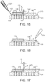
- An exemplary method for utilizing such a cover may be understood by referring now to FIGS. 15 and 16 and initially to FIG. 15 , which is a sectional view of the semiconductor chip 110 mounted to the interposer 120 and secured thereto by the interface structures 135 as generally described elsewhere herein.
- an alternate exemplary cover 195"" is applied to the surface 215 of the interposer 120 and set off laterally from the sidewall 170 of the semiconductor chip 110 by the preferred minimum spacing X 4 .
- the cover 195"" may be composed of a material or materials that can be either dissolved or otherwise removed from the interposer 120 using either a destructive or semi-destructive technique.
- Exemplary materials for the cover 195"” includes for example negative tone photoresist, metastable materials that undergo phase change in response to stimulation, or even anodized carbon.
- the cover 195"" may be applied as a relatively bulk film as depicted in FIG. 15 . Following the dispensing of the underfill 155 by way of the applicator 220 and a suitable curing process, the aforementioned fillet 165 may be established that abuts a sidewall 265 of the cover 195"".
- the cover 195"" may be subjected to a stimulation represented schematically by the symbol 270 in order to dissolve or otherwise break down the cover 195"" in anticipation of the mounting of another semiconductor chip adjacent to the semiconductor chip 110.
- the stimulation 270 may take on a variety of forms dependent upon the composition and sensitivity of the cover 195"".
- the stimulation 270 might be the introduction of a solvent or an etchant that is able readily break down the cover 195"".
- the cover 195"" is composed of a phase change material then the stimulation might be, for example, radiation or some other stimulant that causes the material 195"" to either break down on its own or by way of introduction of another solvent such as a photoresist developer or other material.
- the interposer 120 may undergo the types of testing and the mounting of another semiconductor chip as described elsewhere herein.
- the cover 195"" may be lifted off of the interposer 120 by way of a suitable lift tape 275 as shown in FIG. 17 .
- the cover 195"" may be applied to the surface 215 of the interposer 120 with the requisite lateral spacing X 4 from the sidewall 170 of the semiconductor chip 110.
- the lift off tape 270 is pulled, the cover 195"" may be lifted off of the surface 215 of the interposer 120.
- the interposer 120 and the semiconductor chip 110 may undergo electrical testing and the mounting of an additional semiconductor chip as described elsewhere herein.
- Multi-chip devices may be configured with more than two semiconductor chips.
- a suitable cover may be fashioned to enable the lateral constraint of underfill flowing from a given semiconductor chip into areas where additional semiconductor chips are slated to be mounted.
- FIG. 18 is a pictorial view.
- an interposer 120' has the semiconductor chip 110 mounted thereto.
- the interposer 120' has areas 280 and 290 slated for mounting of two or more semiconductor chips (not shown). Accordingly, it is desirable to be able to constrain any underfill from proceeding away from the sidewall 170 and an adjacent sidewall 295 of the semiconductor chip 110.
- a cover 195'"" may be fabricated with sidewalls 300 and 305 that are configured to face towards the sidewalls 295 and 170, respectively, of the semiconductor chip 110. In this way, underfill will be constrained by the presence of the sidewalls 300 and 305 during both underfill dispense and curing.
- cover 195""' any of the other features disclosed herein such as trenches and magnets, etc. may be used with this embodiment as well.
Landscapes
- Engineering & Computer Science (AREA)
- Microelectronics & Electronic Packaging (AREA)
- Power Engineering (AREA)
- Computer Hardware Design (AREA)
- Physics & Mathematics (AREA)
- Condensed Matter Physics & Semiconductors (AREA)
- General Physics & Mathematics (AREA)
- Manufacturing & Machinery (AREA)
- Wire Bonding (AREA)
- Encapsulation Of And Coatings For Semiconductor Or Solid State Devices (AREA)
- Structures Or Materials For Encapsulating Or Coating Semiconductor Devices Or Solid State Devices (AREA)
Applications Claiming Priority (2)
| Application Number | Priority Date | Filing Date | Title |
|---|---|---|---|
| US12/878,812 US8691626B2 (en) | 2010-09-09 | 2010-09-09 | Semiconductor chip device with underfill |
| PCT/US2011/051075 WO2012034064A1 (en) | 2010-09-09 | 2011-09-09 | Semiconductor chip device with underfill |
Publications (2)
| Publication Number | Publication Date |
|---|---|
| EP2614521A1 EP2614521A1 (en) | 2013-07-17 |
| EP2614521B1 true EP2614521B1 (en) | 2018-01-24 |
Family
ID=44652038
Family Applications (1)
| Application Number | Title | Priority Date | Filing Date |
|---|---|---|---|
| EP11757730.4A Active EP2614521B1 (en) | 2010-09-09 | 2011-09-09 | Method of assembling a multichip module with underfilled semiconductor chip |
Country Status (6)
| Country | Link |
|---|---|
| US (1) | US8691626B2 (enExample) |
| EP (1) | EP2614521B1 (enExample) |
| JP (1) | JP2013539910A (enExample) |
| KR (1) | KR101571837B1 (enExample) |
| CN (1) | CN103098190A (enExample) |
| WO (1) | WO2012034064A1 (enExample) |
Families Citing this family (31)
| Publication number | Priority date | Publication date | Assignee | Title |
|---|---|---|---|---|
| KR20110099556A (ko) * | 2010-03-02 | 2011-09-08 | 삼성전자주식회사 | 반도체 패키지 테스트장치 |
| TWI496254B (zh) * | 2010-11-01 | 2015-08-11 | 欣興電子股份有限公司 | 嵌埋半導體元件之封裝結構及其製法 |
| US8363418B2 (en) * | 2011-04-18 | 2013-01-29 | Morgan/Weiss Technologies Inc. | Above motherboard interposer with peripheral circuits |
| US8952540B2 (en) | 2011-06-30 | 2015-02-10 | Intel Corporation | In situ-built pin-grid arrays for coreless substrates, and methods of making same |
| US9006004B2 (en) * | 2012-03-23 | 2015-04-14 | Taiwan Semiconductor Manufacturing Company, Ltd. | Probing chips during package formation |
| TWI508249B (zh) | 2012-04-02 | 2015-11-11 | 矽品精密工業股份有限公司 | 封裝件、半導體封裝結構及其製法 |
| US10192810B2 (en) | 2013-06-28 | 2019-01-29 | Intel Corporation | Underfill material flow control for reduced die-to-die spacing in semiconductor packages |
| US9412674B1 (en) * | 2013-10-24 | 2016-08-09 | Xilinx, Inc. | Shielded wire arrangement for die testing |
| US9721852B2 (en) * | 2014-01-21 | 2017-08-01 | International Business Machines Corporation | Semiconductor TSV device package to which other semiconductor device package can be later attached |
| KR101622453B1 (ko) * | 2014-01-22 | 2016-05-31 | 앰코 테크놀로지 코리아 주식회사 | 반도체 디바이스 및 그 제조 방법 |
| US9230936B2 (en) * | 2014-03-04 | 2016-01-05 | Qualcomm Incorporated | Integrated device comprising high density interconnects and redistribution layers |
| US9373559B2 (en) * | 2014-03-05 | 2016-06-21 | International Business Machines Corporation | Low-stress dual underfill packaging |
| JP2016115840A (ja) * | 2014-12-16 | 2016-06-23 | ソニー株式会社 | 半導体装置、固体撮像素子、撮像装置、および電子機器 |
| US9437576B1 (en) * | 2015-03-23 | 2016-09-06 | Advanced Semiconductor Engineering, Inc. | Semiconductor device package and method of manufacturing the same |
| US9798088B2 (en) * | 2015-11-05 | 2017-10-24 | Globalfoundries Inc. | Barrier structures for underfill blockout regions |
| US9627784B1 (en) | 2015-12-01 | 2017-04-18 | International Business Machines Corporation | Method and apparatus for strain relieving surface mount attached connectors |
| US10701800B2 (en) * | 2016-01-28 | 2020-06-30 | Hewlett Packard Enterprise Development Lp | Printed circuit boards |
| US10249515B2 (en) * | 2016-04-01 | 2019-04-02 | Intel Corporation | Electronic device package |
| WO2017199278A1 (ja) * | 2016-05-16 | 2017-11-23 | 株式会社日立製作所 | 半導体装置 |
| US10475766B2 (en) * | 2017-03-29 | 2019-11-12 | Intel Corporation | Microelectronics package providing increased memory component density |
| US10304800B2 (en) * | 2017-06-23 | 2019-05-28 | Taiwan Semiconductor Manufacturing Company Ltd. | Packaging with substrates connected by conductive bumps |
| US10529693B2 (en) | 2017-11-29 | 2020-01-07 | Advanced Micro Devices, Inc. | 3D stacked dies with disparate interconnect footprints |
| US10727204B2 (en) | 2018-05-29 | 2020-07-28 | Advances Micro Devices, Inc. | Die stacking for multi-tier 3D integration |
| US10937755B2 (en) | 2018-06-29 | 2021-03-02 | Advanced Micro Devices, Inc. | Bond pads for low temperature hybrid bonding |
| JP2020150145A (ja) * | 2019-03-14 | 2020-09-17 | キオクシア株式会社 | 半導体装置 |
| KR102689648B1 (ko) | 2020-02-03 | 2024-07-30 | 삼성전자주식회사 | 댐 구조물을 갖는 반도체 패키지 |
| CN113571430B (zh) * | 2020-04-28 | 2025-10-31 | 桑迪士克科技股份有限公司 | 具有减小的底部填充面积的倒装芯片封装体 |
| KR102825809B1 (ko) * | 2020-07-10 | 2025-06-27 | 삼성전자주식회사 | 언더필이 구비된 반도체 패키지 및 이의 제조 방법 |
| KR102853612B1 (ko) | 2020-07-15 | 2025-09-03 | 삼성전자주식회사 | 반도체 패키지 및 이의 제조 방법 |
| KR20230032592A (ko) * | 2021-08-31 | 2023-03-07 | 삼성전자주식회사 | 반도체 패키지 |
| JP2023109410A (ja) * | 2022-01-27 | 2023-08-08 | エスケーハイニックス株式会社 | Tsv用モールドアンダーフィル組成物 |
Citations (1)
| Publication number | Priority date | Publication date | Assignee | Title |
|---|---|---|---|---|
| JPH1074868A (ja) * | 1996-08-30 | 1998-03-17 | Oki Electric Ind Co Ltd | 半導体実装装置及び半導体装置の封止方法 |
Family Cites Families (20)
| Publication number | Priority date | Publication date | Assignee | Title |
|---|---|---|---|---|
| JP3065753B2 (ja) | 1991-12-04 | 2000-07-17 | イビデン株式会社 | 半導体集積回路ベアチップの樹脂封止方法、半導体装置 |
| US5901041A (en) * | 1997-12-02 | 1999-05-04 | Northern Telecom Limited | Flexible integrated circuit package |
| JP2000311905A (ja) | 1999-04-28 | 2000-11-07 | Nippon Inter Electronics Corp | 複合半導体装置の製造方法 |
| JP2000357768A (ja) | 1999-06-17 | 2000-12-26 | Hitachi Ltd | 半導体装置及びその製造方法 |
| US6589802B1 (en) * | 1999-12-24 | 2003-07-08 | Hitachi, Ltd. | Packaging structure and method of packaging electronic parts |
| US6949822B2 (en) * | 2000-03-17 | 2005-09-27 | International Rectifier Corporation | Semiconductor multichip module package with improved thermal performance; reduced size and improved moisture resistance |
| US6537482B1 (en) | 2000-08-08 | 2003-03-25 | Micron Technology, Inc. | Underfill and encapsulation of carrier substrate-mounted flip-chip components using stereolithography |
| JP2002124654A (ja) * | 2000-10-13 | 2002-04-26 | Mitsubishi Electric Corp | 固体撮像装置 |
| US6906415B2 (en) | 2002-06-27 | 2005-06-14 | Micron Technology, Inc. | Semiconductor device assemblies and packages including multiple semiconductor devices and methods |
| TW569416B (en) | 2002-12-19 | 2004-01-01 | Via Tech Inc | High density multi-chip module structure and manufacturing method thereof |
| US7122906B2 (en) | 2004-01-29 | 2006-10-17 | Micron Technology, Inc. | Die-wafer package and method of fabricating same |
| US7208342B2 (en) * | 2004-05-27 | 2007-04-24 | Intel Corporation | Package warpage control |
| JP2006261566A (ja) * | 2005-03-18 | 2006-09-28 | Alps Electric Co Ltd | 電子部品用ホルダ及び電子部品用保持シート、これらを用いた電子モジュール、電子モジュールの積層体、電子モジュールの製造方法並びに検査方法 |
| CN1949487A (zh) * | 2005-10-10 | 2007-04-18 | 南茂科技股份有限公司 | 可防止密封材料溢流的膜上倒装片封装结构 |
| JP2007183164A (ja) * | 2006-01-06 | 2007-07-19 | Fujitsu Ltd | 半導体集積回路装置及びその試験方法 |
| JP4391508B2 (ja) * | 2006-09-29 | 2009-12-24 | Okiセミコンダクタ株式会社 | 半導体装置、及び半導体装置の製造方法 |
| JP2008283004A (ja) * | 2007-05-11 | 2008-11-20 | Matsushita Electric Ind Co Ltd | 半導体装置 |
| JP5098498B2 (ja) * | 2007-08-06 | 2012-12-12 | 株式会社デンソー | 電子装置 |
| JP2009158623A (ja) * | 2007-12-26 | 2009-07-16 | Panasonic Corp | 半導体装置の製造方法 |
| CN101777502B (zh) * | 2009-01-13 | 2011-12-07 | 日月光半导体制造股份有限公司 | 倒装芯片封装方法 |
-
2010
- 2010-09-09 US US12/878,812 patent/US8691626B2/en active Active
-
2011
- 2011-09-09 EP EP11757730.4A patent/EP2614521B1/en active Active
- 2011-09-09 WO PCT/US2011/051075 patent/WO2012034064A1/en not_active Ceased
- 2011-09-09 CN CN2011800433411A patent/CN103098190A/zh active Pending
- 2011-09-09 JP JP2013528347A patent/JP2013539910A/ja active Pending
- 2011-09-09 KR KR1020137007013A patent/KR101571837B1/ko active Active
Patent Citations (1)
| Publication number | Priority date | Publication date | Assignee | Title |
|---|---|---|---|---|
| JPH1074868A (ja) * | 1996-08-30 | 1998-03-17 | Oki Electric Ind Co Ltd | 半導体実装装置及び半導体装置の封止方法 |
Also Published As
| Publication number | Publication date |
|---|---|
| WO2012034064A1 (en) | 2012-03-15 |
| KR101571837B1 (ko) | 2015-11-25 |
| US20120061853A1 (en) | 2012-03-15 |
| US8691626B2 (en) | 2014-04-08 |
| JP2013539910A (ja) | 2013-10-28 |
| CN103098190A (zh) | 2013-05-08 |
| EP2614521A1 (en) | 2013-07-17 |
| KR20130109116A (ko) | 2013-10-07 |
Similar Documents
| Publication | Publication Date | Title |
|---|---|---|
| EP2614521B1 (en) | Method of assembling a multichip module with underfilled semiconductor chip | |
| US8736065B2 (en) | Multi-chip package having a substrate with a plurality of vertically embedded die and a process of forming the same | |
| KR101160405B1 (ko) | 고밀도의 범프없는 빌드업 층들 및 더 낮은 밀도의 코어 또는 코어없는 기판을 포함하는 집적회로 패키지들 | |
| US10096541B2 (en) | Method for fabricating electronic package | |
| CN101221937A (zh) | 具有晶粒容纳通孔之晶圆级封装与其方法 | |
| CN108074905B (zh) | 电子装置及其制法与基板结构 | |
| WO2022182465A1 (en) | Nested interposer with through-silicon via bridge die | |
| US11682619B2 (en) | Package component, semiconductor package and manufacturing method thereof | |
| TW201911508A (zh) | 電子封裝件 | |
| US12347758B2 (en) | Dual-underfill encapsulation for packaging and methods of forming the same | |
| CN108807307A (zh) | 具有多个共面中介元件的半导体封装 | |
| US12412827B2 (en) | Semiconductor die package with conductive line crack prevention design | |
| US20250357227A1 (en) | Methods of forming anchor-containing underfill structures for a chip package | |
| US20240088052A1 (en) | Patternable die attach materials and processes for patterning | |
| US20250309171A1 (en) | Semiconductor package with ball grid array connection having improved reliability | |
| TW202326962A (zh) | 與玻璃核心基板耦接的多個晶粒 | |
| US20240321758A1 (en) | Deformation-resistant interposer for a local silicon interconnect and methods for forming the same | |
| US10157839B1 (en) | Interconnect structure and manufacturing method thereof | |
| CN116741740A (zh) | 封装结构及其制造方法 |
Legal Events
| Date | Code | Title | Description |
|---|---|---|---|
| PUAI | Public reference made under article 153(3) epc to a published international application that has entered the european phase |
Free format text: ORIGINAL CODE: 0009012 |
|
| 17P | Request for examination filed |
Effective date: 20130325 |
|
| AK | Designated contracting states |
Kind code of ref document: A1 Designated state(s): AL AT BE BG CH CY CZ DE DK EE ES FI FR GB GR HR HU IE IS IT LI LT LU LV MC MK MT NL NO PL PT RO RS SE SI SK SM TR |
|
| DAX | Request for extension of the european patent (deleted) | ||
| 17Q | First examination report despatched |
Effective date: 20140317 |
|
| RIC1 | Information provided on ipc code assigned before grant |
Ipc: H01L 25/065 20060101ALI20170824BHEP Ipc: H01L 21/56 20060101AFI20170824BHEP |
|
| GRAP | Despatch of communication of intention to grant a patent |
Free format text: ORIGINAL CODE: EPIDOSNIGR1 |
|
| INTG | Intention to grant announced |
Effective date: 20171103 |
|
| GRAS | Grant fee paid |
Free format text: ORIGINAL CODE: EPIDOSNIGR3 |
|
| GRAA | (expected) grant |
Free format text: ORIGINAL CODE: 0009210 |
|
| AK | Designated contracting states |
Kind code of ref document: B1 Designated state(s): AL AT BE BG CH CY CZ DE DK EE ES FI FR GB GR HR HU IE IS IT LI LT LU LV MC MK MT NL NO PL PT RO RS SE SI SK SM TR |
|
| REG | Reference to a national code |
Ref country code: GB Ref legal event code: FG4D |
|
| REG | Reference to a national code |
Ref country code: CH Ref legal event code: EP |
|
| REG | Reference to a national code |
Ref country code: AT Ref legal event code: REF Ref document number: 966227 Country of ref document: AT Kind code of ref document: T Effective date: 20180215 |
|
| REG | Reference to a national code |
Ref country code: IE Ref legal event code: FG4D |
|
| REG | Reference to a national code |
Ref country code: DE Ref legal event code: R096 Ref document number: 602011045302 Country of ref document: DE |
|
| RAP2 | Party data changed (patent owner data changed or rights of a patent transferred) |
Owner name: ADVANCED MICRO DEVICES, INC. Owner name: ATI TECHNOLOGIES ULC |
|
| RAP2 | Party data changed (patent owner data changed or rights of a patent transferred) |
Owner name: ATI TECHNOLOGIES ULC Owner name: ADVANCED MICRO DEVICES, INC. |
|
| REG | Reference to a national code |
Ref country code: NL Ref legal event code: MP Effective date: 20180124 |
|
| REG | Reference to a national code |
Ref country code: LT Ref legal event code: MG4D |
|
| REG | Reference to a national code |
Ref country code: AT Ref legal event code: MK05 Ref document number: 966227 Country of ref document: AT Kind code of ref document: T Effective date: 20180124 |
|
| PG25 | Lapsed in a contracting state [announced via postgrant information from national office to epo] |
Ref country code: NL Free format text: LAPSE BECAUSE OF FAILURE TO SUBMIT A TRANSLATION OF THE DESCRIPTION OR TO PAY THE FEE WITHIN THE PRESCRIBED TIME-LIMIT Effective date: 20180124 |
|
| PG25 | Lapsed in a contracting state [announced via postgrant information from national office to epo] |
Ref country code: FI Free format text: LAPSE BECAUSE OF FAILURE TO SUBMIT A TRANSLATION OF THE DESCRIPTION OR TO PAY THE FEE WITHIN THE PRESCRIBED TIME-LIMIT Effective date: 20180124 Ref country code: HR Free format text: LAPSE BECAUSE OF FAILURE TO SUBMIT A TRANSLATION OF THE DESCRIPTION OR TO PAY THE FEE WITHIN THE PRESCRIBED TIME-LIMIT Effective date: 20180124 Ref country code: CY Free format text: LAPSE BECAUSE OF FAILURE TO SUBMIT A TRANSLATION OF THE DESCRIPTION OR TO PAY THE FEE WITHIN THE PRESCRIBED TIME-LIMIT Effective date: 20180124 Ref country code: NO Free format text: LAPSE BECAUSE OF FAILURE TO SUBMIT A TRANSLATION OF THE DESCRIPTION OR TO PAY THE FEE WITHIN THE PRESCRIBED TIME-LIMIT Effective date: 20180424 Ref country code: ES Free format text: LAPSE BECAUSE OF FAILURE TO SUBMIT A TRANSLATION OF THE DESCRIPTION OR TO PAY THE FEE WITHIN THE PRESCRIBED TIME-LIMIT Effective date: 20180124 Ref country code: LT Free format text: LAPSE BECAUSE OF FAILURE TO SUBMIT A TRANSLATION OF THE DESCRIPTION OR TO PAY THE FEE WITHIN THE PRESCRIBED TIME-LIMIT Effective date: 20180124 |
|
| PG25 | Lapsed in a contracting state [announced via postgrant information from national office to epo] |
Ref country code: GR Free format text: LAPSE BECAUSE OF FAILURE TO SUBMIT A TRANSLATION OF THE DESCRIPTION OR TO PAY THE FEE WITHIN THE PRESCRIBED TIME-LIMIT Effective date: 20180425 Ref country code: IS Free format text: LAPSE BECAUSE OF FAILURE TO SUBMIT A TRANSLATION OF THE DESCRIPTION OR TO PAY THE FEE WITHIN THE PRESCRIBED TIME-LIMIT Effective date: 20180524 Ref country code: RS Free format text: LAPSE BECAUSE OF FAILURE TO SUBMIT A TRANSLATION OF THE DESCRIPTION OR TO PAY THE FEE WITHIN THE PRESCRIBED TIME-LIMIT Effective date: 20180124 Ref country code: BG Free format text: LAPSE BECAUSE OF FAILURE TO SUBMIT A TRANSLATION OF THE DESCRIPTION OR TO PAY THE FEE WITHIN THE PRESCRIBED TIME-LIMIT Effective date: 20180424 Ref country code: LV Free format text: LAPSE BECAUSE OF FAILURE TO SUBMIT A TRANSLATION OF THE DESCRIPTION OR TO PAY THE FEE WITHIN THE PRESCRIBED TIME-LIMIT Effective date: 20180124 Ref country code: AT Free format text: LAPSE BECAUSE OF FAILURE TO SUBMIT A TRANSLATION OF THE DESCRIPTION OR TO PAY THE FEE WITHIN THE PRESCRIBED TIME-LIMIT Effective date: 20180124 Ref country code: SE Free format text: LAPSE BECAUSE OF FAILURE TO SUBMIT A TRANSLATION OF THE DESCRIPTION OR TO PAY THE FEE WITHIN THE PRESCRIBED TIME-LIMIT Effective date: 20180124 Ref country code: PL Free format text: LAPSE BECAUSE OF FAILURE TO SUBMIT A TRANSLATION OF THE DESCRIPTION OR TO PAY THE FEE WITHIN THE PRESCRIBED TIME-LIMIT Effective date: 20180124 |
|
| REG | Reference to a national code |
Ref country code: DE Ref legal event code: R097 Ref document number: 602011045302 Country of ref document: DE |
|
| PG25 | Lapsed in a contracting state [announced via postgrant information from national office to epo] |
Ref country code: EE Free format text: LAPSE BECAUSE OF FAILURE TO SUBMIT A TRANSLATION OF THE DESCRIPTION OR TO PAY THE FEE WITHIN THE PRESCRIBED TIME-LIMIT Effective date: 20180124 Ref country code: RO Free format text: LAPSE BECAUSE OF FAILURE TO SUBMIT A TRANSLATION OF THE DESCRIPTION OR TO PAY THE FEE WITHIN THE PRESCRIBED TIME-LIMIT Effective date: 20180124 Ref country code: IT Free format text: LAPSE BECAUSE OF FAILURE TO SUBMIT A TRANSLATION OF THE DESCRIPTION OR TO PAY THE FEE WITHIN THE PRESCRIBED TIME-LIMIT Effective date: 20180124 Ref country code: AL Free format text: LAPSE BECAUSE OF FAILURE TO SUBMIT A TRANSLATION OF THE DESCRIPTION OR TO PAY THE FEE WITHIN THE PRESCRIBED TIME-LIMIT Effective date: 20180124 |
|
| PG25 | Lapsed in a contracting state [announced via postgrant information from national office to epo] |
Ref country code: DK Free format text: LAPSE BECAUSE OF FAILURE TO SUBMIT A TRANSLATION OF THE DESCRIPTION OR TO PAY THE FEE WITHIN THE PRESCRIBED TIME-LIMIT Effective date: 20180124 Ref country code: SK Free format text: LAPSE BECAUSE OF FAILURE TO SUBMIT A TRANSLATION OF THE DESCRIPTION OR TO PAY THE FEE WITHIN THE PRESCRIBED TIME-LIMIT Effective date: 20180124 Ref country code: SM Free format text: LAPSE BECAUSE OF FAILURE TO SUBMIT A TRANSLATION OF THE DESCRIPTION OR TO PAY THE FEE WITHIN THE PRESCRIBED TIME-LIMIT Effective date: 20180124 Ref country code: CZ Free format text: LAPSE BECAUSE OF FAILURE TO SUBMIT A TRANSLATION OF THE DESCRIPTION OR TO PAY THE FEE WITHIN THE PRESCRIBED TIME-LIMIT Effective date: 20180124 |
|
| PLBE | No opposition filed within time limit |
Free format text: ORIGINAL CODE: 0009261 |
|
| STAA | Information on the status of an ep patent application or granted ep patent |
Free format text: STATUS: NO OPPOSITION FILED WITHIN TIME LIMIT |
|
| 26N | No opposition filed |
Effective date: 20181025 |
|
| PG25 | Lapsed in a contracting state [announced via postgrant information from national office to epo] |
Ref country code: SI Free format text: LAPSE BECAUSE OF FAILURE TO SUBMIT A TRANSLATION OF THE DESCRIPTION OR TO PAY THE FEE WITHIN THE PRESCRIBED TIME-LIMIT Effective date: 20180124 |
|
| PG25 | Lapsed in a contracting state [announced via postgrant information from national office to epo] |
Ref country code: MC Free format text: LAPSE BECAUSE OF FAILURE TO SUBMIT A TRANSLATION OF THE DESCRIPTION OR TO PAY THE FEE WITHIN THE PRESCRIBED TIME-LIMIT Effective date: 20180124 |
|
| REG | Reference to a national code |
Ref country code: CH Ref legal event code: PL |
|
| REG | Reference to a national code |
Ref country code: BE Ref legal event code: MM Effective date: 20180930 |
|
| REG | Reference to a national code |
Ref country code: IE Ref legal event code: MM4A |
|
| PG25 | Lapsed in a contracting state [announced via postgrant information from national office to epo] |
Ref country code: LU Free format text: LAPSE BECAUSE OF NON-PAYMENT OF DUE FEES Effective date: 20180909 |
|
| PG25 | Lapsed in a contracting state [announced via postgrant information from national office to epo] |
Ref country code: IE Free format text: LAPSE BECAUSE OF NON-PAYMENT OF DUE FEES Effective date: 20180909 |
|
| PG25 | Lapsed in a contracting state [announced via postgrant information from national office to epo] |
Ref country code: CH Free format text: LAPSE BECAUSE OF NON-PAYMENT OF DUE FEES Effective date: 20180930 Ref country code: LI Free format text: LAPSE BECAUSE OF NON-PAYMENT OF DUE FEES Effective date: 20180930 Ref country code: FR Free format text: LAPSE BECAUSE OF NON-PAYMENT OF DUE FEES Effective date: 20180930 Ref country code: BE Free format text: LAPSE BECAUSE OF NON-PAYMENT OF DUE FEES Effective date: 20180930 |
|
| PG25 | Lapsed in a contracting state [announced via postgrant information from national office to epo] |
Ref country code: MT Free format text: LAPSE BECAUSE OF NON-PAYMENT OF DUE FEES Effective date: 20180909 |
|
| PG25 | Lapsed in a contracting state [announced via postgrant information from national office to epo] |
Ref country code: TR Free format text: LAPSE BECAUSE OF FAILURE TO SUBMIT A TRANSLATION OF THE DESCRIPTION OR TO PAY THE FEE WITHIN THE PRESCRIBED TIME-LIMIT Effective date: 20180124 |
|
| PG25 | Lapsed in a contracting state [announced via postgrant information from national office to epo] |
Ref country code: HU Free format text: LAPSE BECAUSE OF FAILURE TO SUBMIT A TRANSLATION OF THE DESCRIPTION OR TO PAY THE FEE WITHIN THE PRESCRIBED TIME-LIMIT; INVALID AB INITIO Effective date: 20110909 Ref country code: PT Free format text: LAPSE BECAUSE OF FAILURE TO SUBMIT A TRANSLATION OF THE DESCRIPTION OR TO PAY THE FEE WITHIN THE PRESCRIBED TIME-LIMIT Effective date: 20180124 |
|
| PG25 | Lapsed in a contracting state [announced via postgrant information from national office to epo] |
Ref country code: MK Free format text: LAPSE BECAUSE OF NON-PAYMENT OF DUE FEES Effective date: 20180124 |
|
| P01 | Opt-out of the competence of the unified patent court (upc) registered |
Effective date: 20230530 |
|
| PGFP | Annual fee paid to national office [announced via postgrant information from national office to epo] |
Ref country code: DE Payment date: 20250819 Year of fee payment: 15 |
|
| PGFP | Annual fee paid to national office [announced via postgrant information from national office to epo] |
Ref country code: GB Payment date: 20250911 Year of fee payment: 15 |