EP2611136A2 - Vorrichtung zur Erzeugung einer Farbumwandlungstabelle, Verfahren zur Erzeugung einer Farbumwandlungstabelle und Speichermedium - Google Patents
Vorrichtung zur Erzeugung einer Farbumwandlungstabelle, Verfahren zur Erzeugung einer Farbumwandlungstabelle und Speichermedium Download PDFInfo
- Publication number
- EP2611136A2 EP2611136A2 EP12197361.4A EP12197361A EP2611136A2 EP 2611136 A2 EP2611136 A2 EP 2611136A2 EP 12197361 A EP12197361 A EP 12197361A EP 2611136 A2 EP2611136 A2 EP 2611136A2
- Authority
- EP
- European Patent Office
- Prior art keywords
- component
- color
- color conversion
- amount limiting
- material amount
- Prior art date
- Legal status (The legal status is an assumption and is not a legal conclusion. Google has not performed a legal analysis and makes no representation as to the accuracy of the status listed.)
- Granted
Links
Images







Classifications
-
- H—ELECTRICITY
- H04—ELECTRIC COMMUNICATION TECHNIQUE
- H04N—PICTORIAL COMMUNICATION, e.g. TELEVISION
- H04N1/00—Scanning, transmission or reproduction of documents or the like, e.g. facsimile transmission; Details thereof
- H04N1/46—Colour picture communication systems
- H04N1/56—Processing of colour picture signals
- H04N1/60—Colour correction or control
- H04N1/6016—Conversion to subtractive colour signals
- H04N1/6019—Conversion to subtractive colour signals using look-up tables
-
- H—ELECTRICITY
- H04—ELECTRIC COMMUNICATION TECHNIQUE
- H04N—PICTORIAL COMMUNICATION, e.g. TELEVISION
- H04N1/00—Scanning, transmission or reproduction of documents or the like, e.g. facsimile transmission; Details thereof
- H04N1/46—Colour picture communication systems
- H04N1/56—Processing of colour picture signals
- H04N1/60—Colour correction or control
Definitions
- the present invention relates to a color conversion table creating device, a color conversion table creating method, and storage medium.
- CMYK data for output from a printer
- LUT Look Up Table
- image data including cyan (C), magenta (M), yellow (Y), and black (K)
- CMYK data for output from a printer
- the CMY component and the K component are calculated separately. Therefore, when the color material amount is limited by limiting a total amount of each color component after color conversion, there is a possibility that the CMYK value changes by the color material amount limit, the corresponding relation with the three dimensional LUT used in color conversion does not match and the accuracy of color conversion decreases.
- the color material toner, ink, etc.
- problems such as fusing defect of toner in an electro-photographic printer and blurring in an inkjet printer, etc. occur. Therefore, normally the total amount of the color material is fixed.
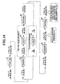
- FIG. 14 is an example of conversion when the total CMYK amount is relatively small and FIG. 15 is an example of conversion when the total CMYK amount is large and the total toner amount is adjusted.
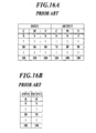
- FIG. 16A is an example of a CMY three dimensional LUT and FIG. 16B is an example of a K one dimensional LUT.
- CMYK value is (80, 80, 80, 0)
- the K value (0) is converted to (70, 80, 90).
- the K value (0) is converted to (0).
- the converted CMY value (70, 80, 90) and the converted K value (0) are combined and it is judged whether there is a toner amount limit on the combined CMYK value (70, 80, 90, 0).
- the toner amount limit value maximum value of total CMYK amount
- the total CMYK amount is relatively small, the CMYK value does not change by the toner amount limiting and therefore there is no problem.
- the input CMYK value is (80, 80, 80, 100)
- the values are divided between the CMY value (80, 80, 90) and the K value (100).
- the CMY value (80, 80, 80) the CMY three dimensional LUT shown in FIG. 16A is referred, and the CMY value is converted to (70, 80, 90).
- the K value (100) the K one dimensional LUT shown in FIG. 16B is referred and the K value is converted to (100).
- the converted CMY value (70, 80, 90) and the converted K value (100) are combined and it is judged whether there is a toner amount limit on the combined CMYK value (70, 80, 90, 100).
- the CMY value (40, 50, 60) is a value which has no relation with the output value (70, 80, 90) from the referred CMY three dimensional LUT and is a value with no guarantee.
- the present invention has been made in consideration of the above problems, and it is one of main objects to prevent reduction of accuracy of color conversion using a color conversion table by considering color material amount being limited after color conversion when a color conversion table is created based on a three dimensional table of cyan, magenta, and yellow and a one dimensional table of black.
- a color conversion table creating device which creates a color conversion table for color conversion from input image data including cyan, magenta, yellow, and black to output image data including cyan, magenta, yellow, and black, the device characterized by:
- the color conversion table creating device further includes:
- FIG. 1 shows a system configuration of a print system 100.
- the print system 100 includes a printer 10, a controller 20, a color conversion table creating device 30, print instruction terminals 40a, 40b, etc. and each device is connected to each other through a communication network N to enable data communication.
- the printer 10 is an image forming apparatus which prints based on image data (CMYK data) in a bitmap format received from the controller 20.
- the printer 10 uses toner as color material to form an image in an electro-photographic format.
- the printer 10 includes a photoreceptor drum, a charging section which charges the photoreceptor drum, an exposing section which exposes light to scan a surface of the photoreceptor drum based on the image data (CMYK), a developing section which attaches toner of each color of CMYK to the photoreceptor drum, a transferring section which transfers a toner image formed on the photoreceptor drum on print paper, a fusing section which fuses the toner image formed on the print paper, and the like.
- the controller 20 performs processing such as rasterizing, color conversion, screening, and toner amount limit as color material amount limit on the print data transmitted from the print instruction terminals 40a, 40b, etc.
- the controller 20 transmits the processed image data to the printer 10.
- the controller 20 can be included in the printer 10.
- the controller 20 and the printer 10 can be connected through PCI connection, exclusive line, etc.
- the color conversion table creating device 30 uses a color measurement value of a chart (color chart) for creating a color conversion table output from the printer 10 to create a color conversion table of CMYK ⁇ CMYK (color conversion LUT).
- the color conversion LUT is a table showing corresponding relation to perform color conversion of input image data including cyan, magenta, yellow, and black to output image data including cyan, magenta, yellow, and black.
- the color conversion table is created for each output condition of printing such as paper type, screen type, etc.
- the color conversion table creating device 30 can be included in the controller 20 or the printer 10.
- the print instruction terminals 40a, 40b, etc. use the printer driver program and dedicated software to instruct print to the controller 20. Specifically, the print instruction terminals 40a, 40b, etc. generate print data described with a page description language (PDL) which can be interpreted by the controller 20 and the generated print data is transmitted to the controller 20.
- PDL page description language
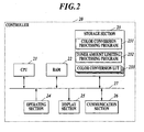
- FIG. 2 shows a functional configuration of the controller 20.
- the controller 20 includes a CPU (Central Processing Unit) 21, a RAM (Random Access Memory) 22, a storage section 23, an operating section 24, a display section 25, a communication section 26, etc. and each section is connected to each other through a bus 27.
- CPU Central Processing Unit
- RAM Random Access Memory
- the CPU 21 centrally controls the processing operation of each section of the controller 20. According to the operation signal input from the operating section 24 or the instruction signal received by the communication section 26, the CPU 21 reads various processing programs stored in the storage section 23 and expands the programs in the RAM 22, and the CPU 21 performs various processing in coordination with the programs.
- the RAM 22 forms a work area which temporarily stores various processing programs performed by the CPU 21 and the data regarding the programs.
- the storage section 23 includes a storage device such as a nonvolatile semiconductor memory, hard disk, etc., and stores various processing programs, data regarding the various programs and the like.
- the storage section 23 stores a color conversion processing program 231, a toner amount limiting processing program 232, a color conversion LUT 233, and the like.
- the operating section 24 includes a keyboard including cursor keys, character input keys, various function keys, etc. and a pointing device such as a mouse, and the operating section 24 receives input of operation by the user.
- the operating section 24 outputs to the CPU 21 an operating signal input by the key operation on the keyboard or the mouse operation.
- the display section 25 includes an LCD (Liquid Crystal Display) and displays various operation screens and various processing results according to the instruction from the CPU 21.
- LCD Liquid Crystal Display
- the communication section 26 transmits and receives data between an external device through the communication network N.
- the communication section 26 receives the color conversion LUT created by the color conversion table creating device 30.
- the communication section 26 receives the print data from the print instruction terminals 40a, 40b, etc.
- the communication section 26 transmits the image data in a bitmap format to the printer 10.
- the CPU 21 stores the color conversion LUT received from the color conversion table creating device 30 as the color conversion LUT 233 in the storage unit 23.
- the CPU 21 analyzes the print data (PDL data) received from the print instruction terminals 40a, 40b, etc. and expands the image data in a bitmap format (RIP (Raster Image Processor) processing).
- PDL data print data
- RIP Raster Image Processor
- the CPU 21 uses the color conversion LUT 233 stored in the storage section 23 to perform the color conversion of CMYK ⁇ CMYK on the image data. Specifically, the CPU 21 refers to the color conversion LUT 233 and obtains the combination of the output value corresponding to the combination of the input value which matches the CMYK value of the input image data or the combination of the input value which is close to the CMYK value of the input image data. Then, the CPU 21 performs interpolation processing to calculate the CMYK value after color conversion.
- the CPU 21 limits toner amount of the image data after color conversion.
- the mapping from the CMYK value before processing to the CMYK value after processing can be shown by a formula or can be obtained by interpolation processing using the look up table.
- FIG. 3 shows a functional configuration of the color conversion table creating device 30.
- the color conversion table creating device 30 includes a CPU 31, a RAM 32, a storage section 33, an operating section 34, a display section 35, a communication section 36, a color measuring device IF (interface) section 37 and the like, and each section is connected to each other through a bus 38.
- the CPU 31 centrally controls the processing operation of each section of the color conversion table creating device 30. According to the operation signal input from the operating section 34 or the instruction signal received by the communication section 36, the CPU 31 reads various processing programs stored in the storage section 33 and expands the programs in the RAM 32, and the CPU 31 performs various processing in coordination with the programs.
- the RAM 32 forms a work area which temporarily stores various processing programs performed by the CPU 31 and the data regarding the programs.
- the storage section 33 includes a storage device such as a nonvolatile semiconductor memory, hard disk, etc., and stores various processing programs, data regarding the various programs and the like.
- the storage section 33 stores a color conversion table creating processing program 331, and the like.
- the operating section 34 includes a keyboard including cursor keys, character input keys, various function keys, etc. and a pointing device such as a mouse, and the operating section 34 receives input of operation by the user.
- the operating section 34 outputs to the CPU 31 an operating signal input by the key operation on the keyboard or the mouse operation.
- the operating section 34 is used for instructing the printer 10 to print the chart for creating the color conversion LUT.
- the display section 35 includes an LCD (Liquid Crystal Display) and displays various operation screens and various processing results according to the instruction from the CPU 31.
- LCD Liquid Crystal Display
- the communication section 36 transmits and receives data between an external device through the communication network N.
- the communication section 36 transmits the color conversion LUT created in the color conversion table creating device 30 to the controller 20.
- the color measuring device IF section 37 receives from the color measuring device 50 the color measurement value obtained by measuring the color of each patch of the chart for creating the color conversion LUT.
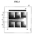
- FIG. 4 shows a chart sample CS which is a sample of an image used in output of the chart for creating the color conversion LUT.
- the chart sample CS includes a tone patch area A1 positioned in a center portion and CMY patch areas A2 and A3 positioned above and below the tone patch area A1.
- the tone patch area A1 is provided with patches of twenty tones in the order from the top CMY (mixed color), K, Y, M, C (20 x 5 patches).
- the CMY patch areas A2 and A3 are provided with color patches including at least one color of C, M, Y.
- 6 x 6 x 6 patches are provided in the CMY patch areas A2 and A3.
- a black bar A4 in the upper portion of the chart sample CS and diamond marks A5 and A6 on the left and right of the chart sample CS are used by the color measuring device 50 to specify the coordinates of each patch automatically and thus are not essential conditions.
- the CPU 31 creates a CMY ⁇ CMY three dimensional LUT (hereinafter referred to as CMY three dimensional LUT) for color conversion from the cyan component, the magenta component, and the yellow component of the input image data to the cyan component, the magenta component, and the yellow component of the output image data based on the color measurement value of the patch formed from the combination of CMY of the chart for creating the color conversion LUT.
- CMY three dimensional LUT CMY ⁇ CMY three dimensional LUT
- the CPU 31 creates a K ⁇ K one dimensional LUT (hereinafter referred to as K one dimensional LUT) for color conversion from the black component of the input image data to the black component of the output image data based on the color measurement value and the white information of the patch formed from single color K of the chart for creating the color conversion LUT.
- K one dimensional LUT K ⁇ K one dimensional LUT
- the CPU 31 creates a CMYK ⁇ CMYK four dimensional LUT (hereinafter referred to as CMYK four dimensional LUT) as the color conversion table for color conversion of input image data including cyan, magenta, yellow, and black to output image data including cyan, magenta, yellow, and black based on the CMY three dimensional LUT and the K one dimensional LUT.
- CMYK four dimensional LUT the color conversion table for color conversion of input image data including cyan, magenta, yellow, and black to output image data including cyan, magenta, yellow, and black based on the CMY three dimensional LUT and the K one dimensional LUT.
- the description of simply "color conversion LUT" refers to the CMYK four dimensional LUT.
- the toner amount limiting is processing which limits the total toner amount of the color components of the image data to a specified toner amount. Specifically, the toner amount limiting converts the CMYK value before toner amount limiting to the CMYK value after toner amount limiting. According to the present embodiment, the CMYK value before toner amount limiting and the CMYK value after toner amount limiting are determined one to one, and the toner amount limiting is invertible.
- the toner amount limiting performed in the color conversion table creating device 30 is performed using the same standard by using the same method as the "toner amount limiting performed in the controller 20".
- the toner amount limiting inverse conversion converts the CMYK value after the toner amount limiting to the CMYK value before toner amount limiting.
- the toner amount limiting inverse conversion performed in the color conversion table creating device 30 is the inverse conversion of the "toner amount limiting performed in the controller 20".
- FIG. 5 shows an outline of the creating processing of the CMYK four dimensional LUT.
- the toner amount limiting performed in the controller 20 is simulated in advance and the CMY three dimensional LUT for when there is a toner amount limit is referred.
- the CPU 31 performs each processing P1 to P6 shown in FIG. 5 , on each combination (CMYK value) of the input value in the CMYK four dimensional LUT to determine the combination (CMYK value) of the output value in the CMYK four dimensional LUT.
- the CPU 31 (color material amount limiting processing section) performs toner amount limiting P1 (described as "TonerLimit” in the figure) which limits the total amount of each color component on the combination of the input value of CMYK in the CMYK four dimensional LUT.
- the CPU 31 (second color material amount limiting inverse conversion processing section) performs toner amount limiting inverse conversion (described as "TonerLimit -1 " in the figure) P2 on the cyan component, the magenta component, and the yellow component after the toner amount limiting P1.
- toner amount limiting inverse conversion P2 the input value of the black component is calculated as 0.
- the CPU 31 (first color conversion processing section) performs color conversion (described as "3D-LUT” in the figure) P3 using the CMY three dimensional LUT on the cyan component, the magenta component, and the yellow component after the toner amount limiting inverse conversion P2.
- the CPU 31 (second color material limiting processing section) performs toner amount limiting P4 on the cyan component, the magenta component, and the yellow component after the color conversion P3.
- the input value of the black component is calculated as 0.
- the CPU 31 (second color conversion processing section) performs color conversion (described as "1D-LUT" in the figure) P5 using the K one dimensional LUT on the black component after the toner amount limiting P1.
- the CPU 31 (combining section) combines the cyan component, the magenta component, and the yellow component after the toner amount limiting P4 with the black component after the color conversion P5.
- the CPU 31 (color material amount limiting inverse conversion processing section) performs toner amount limiting inverse conversion P6 on the combined cyan component, magenta component, yellow component and black component.
- the CPU 31 determines the cyan component, the magenta component, the yellow component, and the black component after the toner amount limiting inverse conversion P6 to be the combination of the output value in the CMYK four dimensional LUT.
- the toner amount limiting P1 the color conversion P3, the color conversion P5 and the toner amount limiting inverse conversion P6 are necessary processing and the toner amount limiting inverse conversion P2, and the toner amount limiting P4 are processing which may be necessary depending on the contents of the CMY three dimensional LUT.
- the present invention creates the CMYK four dimensional LUT using the CMY three dimensional LUT and the K one dimensional LUT and therefore it is clear that the color conversion P3 and the color conversion P5 are necessary.
- the toner amount limiting P1 determines the actual input value of the CMY three dimensional LUT to be referred.
- the point of the present invention is to create a CMYK four dimensional LUT considering that the toner amount is limited in the later processing. Therefore, when the CMYK value is calculated with the toner amount limited by the toner amount limiting P1 or the toner amount limiting P4, it is necessary to once return the value to a value where the toner amount is not limited. By performing the toner amount limiting inverse conversion P6, the controller 20 can correctly perform the toner amount limiting later.
- the toner amount limiting inverse conversion P2 and the toner amount limiting P4 before and after the color conversion P3 using the CMY three dimensional LUT is not necessary.
- the color conversion P3 is performed using the CMY three dimensional LUT on the cyan component, the magenta component, and the yellow component after the toner amount limiting P1, the cyan component, the magenta component, and the yellow component after color conversion P3 is combined with the black component after color conversion P5, and the toner amount limiting inverse conversion P6 is performed on the combined cyan component, magenta component, yellow component, and black component.
- the toner amount limit value is less than 300% when the CMY three dimensional LUT is created, the printing needs to be performed with the toner amount of the toner amount limit or more. Therefore, there is a possibility that paper jamming and problems in transfer occur.
- the CMY three dimensional LUT describing the input and output relation of data before limiting the toner amount is used.
- the input value of the CMY three dimensional LUT needs to be a state in which the toner amount is not limited, and therefore, the toner amount limiting inverse conversion P2 needs to be performed before the color conversion P3 using the CMY three dimensional LUT.
- the inverse conversion (P2, P6) are performed one time more compared to the toner amount limiting (P1), and therefore it is necessary to perform the toner amount limiting P4.
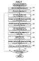
- FIG. 6 is a flowchart showing the color conversion table creating processing performed by the color conversion table creating device 30.
- the color conversion table creating processing is realized with software processing by the CPU 31 in coordination with the color conversion table creating processing program 331 stored in the storage section 33.
- the CPU 31 sets the output condition when the chart is printed such as paper type, screen type, etc. (step S1).
- the color conversion LUT created with this condition is used in the actual color conversion in the RIP processing by the controller 20.
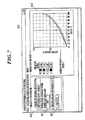
- FIG. 7 shows an example of the color conversion LUT creating screen 351 displayed in the display section 35 of the color conversion table creating device.30.
- the color conversion LUT creating screen 351 includes a creating procedure display area All and a graph display area A12.
- the graph display area A12 displays the maximum density of each color of CMYK of the chart measured for creating the LUT and the output density with respect to % of input of the selected color.
- FIG. 8 shows an example of the chart measuring screen 352 displayed on the display section 35 of the color conversion table creating device 30.
- the chart measuring screen 352 includes a chart output instruction area A21, a measuring instruction area A22, a chart display area A23, and a measurement result display area A24.
- the CPU 31 transmits to the controller 20 data of the chart for creating the color conversion LUT with the set output conditions through the communication section 36 (step S2).
- the controller 20 performs the toner amount limiting on the data of the chart for creating the color conversion LUT and outputs the result to the printer 10.
- the printer 10 prints the chart based on the data of the chart received from the controller 20.
- step S3 when the user operates the operating section 34 and a start button B12 of the measurement instruction area A22 is pressed, the measuring of the chart starts and the CPU 31 obtains the color measurement value acquired by measuring each patch of the output chart using the color measuring device 50 through the color measuring device IF section 37 (step S3).
- the measuring procedure is slightly different depending on the color measuring device 50 used and therefore the procedure can be displayed on the display section 35.
- the chart display area A23 displays the image of the measured chart.
- the measuring result display area A24 displays the CMYK value (%) corresponding to each patch in the chart, the color measurement value (L*a*b*value) obtained by measuring each patch, and the CMYK density.
- the CPU 31 When the user operates the operating section 34 and presses a register button B13, the CPU 31 performs the calculation of the color conversion LUT and the registration to the controller 20 (step S4 to step S7).
- the CPU 31 calculates the CMY three dimensional LUT based on the color measurement value of the patch including C, M, Y of the chart (step S4).
- a typical method is to determine the color measurement value (Japan color, etc.) as the target for each patch in advance and to obtain the output value of the CMY to match the above with the interpolation calculation.
- the CPU 31 calculates the K one dimensional LUT based on the measurement value and the white information of the patch including only K of the chart (step S5).
- K also, the method to obtain by calculation the output value of K to match the predetermined color measurement value is used.
- the value connecting the measurement value space L*value of the L*a*b*space and Y value of XYZ space linearly may be calculated as the target value from the patch information of white and K 100%.
- the CPU 31 calculates the CMYK four dimensional LUT based on the created CMY three dimensional LUT and K one dimensional LUT (step S6).
- the calculating processing of CMYK four dimensional LUT is described later.
- the CPU 31 transmits to the controller 20 the calculated CMYK four dimensional LUT through the communication section 36 (step S7).
- the communication section 26 receives the CMYK four dimensional LUT and the CPU 21 stores the CMYK four dimensional LUT as the color conversion LUT 233 in the storage section 23 (registration of the color conversion LUT).
- step S6 the calculating processing (step S6) of the CMYK four dimensional LUT is described with reference to FIG. 9 .
- the CPU 31 obtains the CMY three dimensional LUT and the K one dimensional LUT acquired by calculation (step S11, S12).
- the CPU 31 performs the processing of step S13 to step S20 on the CMYK value (c, m, y, k) corresponding to the input point of the CMYK four dimensional LUT (color conversion LUT) to be created.
- 11 to the power of 4 (11 tones for each color), 17 to the power of 4, 21 to the power of 4, etc. are often used, but any number of points can be used.
- the number of tones can be different for each color of CMYK, such as CMY being 17 tones and K being 11 tones, etc.
- the CPU 31 performs the toner amount limiting P1 on the c, m, y, k which is the combination of the input value of the CMYK four dimensional LUT (step S13).
- the CMYK value after the toner amount limiting P1 is c 1 , m 1 , y 1 , k 1 .
- the limit value of the total CMYK amount is 250%
- the method used applies 200% through 400% to 200% through 250%.
- an effective method is to reduce only CMY without reducing K.
- K is not changed by the toner amount limiting.
- the CMY value after the toner amount limiting inverse conversion P2 is to be c 2 , m 2 , y 2 .
- the CPU 31 refers to the CMY three dimensional LUT and performs the color conversion P3 on the CMY value (c 2 , m 2 , y 2 ) after toner amount limiting inverse conversion P2 (step S15).
- the CMY value after the color conversion P3 is to be c 3 , m 3 , y 3 .
- the CMY value after the toner amount limiting P4 is to be c 4 , m 4 , y 4 .
- the CPU 31 refers to the K one dimensional LUT and performs the color conversion P5 on the K value (k 1 ) obtained in step S13 (step S17).
- the K value after the color conversion P5 is to be k 2 .
- the CPU 31 combines the CMY value (c 4 , m 4 , y 4 ) calculated in step S16 with the K value (k 2 ) obtained in step S17 and the CMYK value (c 5 , m 5 , y 5 , k 5 ) is obtained (step S18).
- the CPU 31 performs the toner amount limiting inverse conversion P6 on the combined CMYK value (c 5 , m 5 , y 5 , k 5 ) (step S19).
- the CMYK value after the toner amount limiting inverse conversion P6 is to be (c 6 , m 6 , y 6 , k 6 ).
- the CPU 31 stores the CMYK value (c 6 , m 6 , y 6 , k 6 ) after the toner amount limiting inverse conversion P6 as the combination of the output value for the input value (c, m, y, k) in the CMYK four dimensional LUT (step S20).
- step S21 judges whether the processing on all input points is finished.
- step S21 judges whether the processing on all input points is finished.
- step S21 when the processing on all input points is finished (step S21 ; YES), the calculating processing of CMYK four dimensional LUT is finished.
- FIG. 10 shows a first conversion example.
- FIG. 11A is an example of the CMY three dimensional LUT and
- FIG. 11B is an example of the K one dimensional LUT.
- the value (40, 50, 65, 100) is stored as the output value for the input value (80, 80, 80, 100) of the CMYK four dimensional LUT.
- the controller 20 performs color conversion using the CMYK four dimensional LUT created as described above. By performing the CMYK ⁇ CMYK color conversion on the input value (80, 80, 80, 100), the output value (40, 50, 65, 100) can be obtained. Then, the controller 20 later performs toner amount limiting Q1 to obtain, for example (30, 40, 50, 100) as the CMYK value output to the printer 10.
- the CMY value of the value (30, 40, 50, 100) after the toner amount limiting Q1 in the controller 20 matches with the value (30, 40, 50) where the toner amount limiting P4 is performed on the output value of (40, 40, 40) ⁇ (30, 40, 50) of the CMY three dimensional LUT referred when the CMYK four dimensional LUT is created in the color conversion table creating device 30.
- FIG. 12 shows a second conversion example.
- the CMY three dimensional LUT and the K one dimensional LUT shown in FIG. 11A and FIG. 11B are used.
- the value (68, 79, 84, 11) is stored as the output value for the input value (80, 80, 80, 10) of the CMYK four dimensional LUT.
- the controller 20 performs color conversion using the CMYK four dimensional LUT created as described above. By performing the CMYK ⁇ CMYK color conversion on the input value (80, 80, 80, 10), the output value (68, 79, 84, 11) can be obtained. Then, the controller 20 later performs toner amount limiting Q1 to obtain, for example (63, 73, 78, 10) as the CMYK value output to the printer 10.
- the CMY value of the value (63, 73, 78, 10) after toner amount limiting Q1 is performed in the controller 20 matches with the value (63, 73, 78) where the toner amount limiting P4 is performed on the output value of (75, 75, 75) ⁇ (65, 75, 80) of the CMY three dimensional LUT referred when the CMYK four dimensional LUT is created in the color conversion table creating device 30.
- the color conversion table creating device 30 when the color conversion table is created based on the three dimensional table of cyan, magenta, and yellow and the one dimensional table of black, the toner amount limiting performed after color conversion is considered, and it is possible to prevent the decrease of accuracy of color conversion using the created color conversion table.
- a reading section can be provided to read the CMY three dimensional LUT and the K one dimensional LUT in the color conversion table creating device 30.
- FIG. 13 is a flowchart showing another example of the color conversion table creating processing performed in the color conversion table creating device 30.
- the reading section reads the CMY three dimensional LUT and the K one dimensional LUT created by the software or another device (step S31, S32).
- Step S33 and step S34 are similar to step S6 and S7 shown in FIG. 6 , and therefore the description is omitted.
- the CMY three dimensional LUT and the K one dimensional LUT acquired by reading are obtained in step S11 and step S12 of calculating processing of the CMYK four dimensional LUT shown in FIG. 9 .
- one of the CMY three dimensional LUT or the K one dimensional LUT can be obtained by calculation and the other can be obtained by reading an already created LUT.
- the color material amount limiting processing section, the first color conversion processing section, the second color conversion processing section, the combining section, the color material amount limiting inverse conversion processing section, the output value determining section, the second color material amount limiting inverse conversion processing section and the second color material amount limiting processing section which are realized by the CPU 31 in coordination with the color conversion table creating processing program 331 in the color conversion table creating device 30 can be realized by dedicated hardware.
- the present embodiment describes an example of performing toner amount limiting as color material amount limiting.
- color material amount limiting can be performed according to the used color material, such as ink amount limiting which limits the total amount of ink of the color components used.
- the above embodiment discloses an example using a nonvolatile semiconductor memory or a hard disk as a computer readable medium which stores a program to perform each processing.
- the present invention is not limited to the above.
- a portable storage medium such as a CD-ROM, etc.
- a carrier wave can be applied as a medium which provides data of a program through a communication line.
- a color conversion table creating device which creates a color conversion table for color conversion from input image data including cyan, magenta, yellow, and black to output image data including cyan, magenta, yellow, and black, the device characterized by:
- the color conversion table creating device further includes:
- a color conversion table creating method which creates a color conversion table for color conversion from input image data including cyan, magenta, yellow, and black to output image data including cyan, magenta, yellow, and black, the method characterized by:
- a non-transitory computer-readable storage medium having a program stored thereon for controlling a computer which creates a color conversion table for color conversion from input image data including cyan, magenta, yellow, and black to output image data including cyan, magenta, yellow, and black, the program to control the computer to function as the following, characterized by:
Landscapes
- Engineering & Computer Science (AREA)
- Multimedia (AREA)
- Signal Processing (AREA)
- Color Image Communication Systems (AREA)
- Facsimile Image Signal Circuits (AREA)
- Color, Gradation (AREA)
- Color Electrophotography (AREA)
Applications Claiming Priority (1)
| Application Number | Priority Date | Filing Date | Title |
|---|---|---|---|
| JP2011284963A JP5494641B2 (ja) | 2011-12-27 | 2011-12-27 | 色変換テーブル作成装置、色変換テーブル作成方法及びプログラム |
Publications (3)
| Publication Number | Publication Date |
|---|---|
| EP2611136A2 true EP2611136A2 (de) | 2013-07-03 |
| EP2611136A3 EP2611136A3 (de) | 2017-01-04 |
| EP2611136B1 EP2611136B1 (de) | 2018-03-07 |
Family
ID=47605323
Family Applications (1)
| Application Number | Title | Priority Date | Filing Date |
|---|---|---|---|
| EP12197361.4A Active EP2611136B1 (de) | 2011-12-27 | 2012-12-14 | Vorrichtung zur Erzeugung einer Farbumwandlungstabelle, Verfahren zur Erzeugung einer Farbumwandlungstabelle und Speichermedium |
Country Status (4)
| Country | Link |
|---|---|
| US (1) | US8797614B2 (de) |
| EP (1) | EP2611136B1 (de) |
| JP (1) | JP5494641B2 (de) |
| CN (1) | CN103188420B (de) |
Families Citing this family (5)
| Publication number | Priority date | Publication date | Assignee | Title |
|---|---|---|---|---|
| JP5861691B2 (ja) * | 2013-11-21 | 2016-02-16 | コニカミノルタ株式会社 | 色変換テーブル作成方法、色変換テーブル作成プログラム、記録媒体、および色変換テーブル作成装置 |
| JP6079703B2 (ja) * | 2014-06-06 | 2017-02-15 | コニカミノルタ株式会社 | プロファイル作成方法、プロファイル作成プログラム、および記録媒体 |
| US10401227B2 (en) * | 2015-03-26 | 2019-09-03 | Konica Minolta, Inc. | Colorimetry device and colorimetry method |
| JP6623765B2 (ja) | 2016-01-07 | 2019-12-25 | コニカミノルタ株式会社 | 制御装置及び多次元補正方法並びに多次元補正プログラム |
| JP6686542B2 (ja) * | 2016-03-04 | 2020-04-22 | 富士ゼロックス株式会社 | 色処理装置、画像形成システム及びプログラム |
Citations (1)
| Publication number | Priority date | Publication date | Assignee | Title |
|---|---|---|---|---|
| JP2007089031A (ja) | 2005-09-26 | 2007-04-05 | Fuji Xerox Co Ltd | 出力装置 |
Family Cites Families (24)
| Publication number | Priority date | Publication date | Assignee | Title |
|---|---|---|---|---|
| JP3249693B2 (ja) * | 1994-10-17 | 2002-01-21 | 富士ゼロックス株式会社 | 画像処理装置 |
| JP3612200B2 (ja) * | 1997-12-17 | 2005-01-19 | 富士写真フイルム株式会社 | 印刷階調補正方法およびその装置 |
| JP4212742B2 (ja) * | 1999-12-14 | 2009-01-21 | 富士ゼロックス株式会社 | カラー画像処理方法およびカラー画像処理装置 |
| US7190485B2 (en) * | 2001-06-14 | 2007-03-13 | Eastman Kodak Company | Method for multilevel printing of digital images using reduced colorant amounts |
| JP3787534B2 (ja) * | 2002-05-20 | 2006-06-21 | キヤノン株式会社 | 画像処理装置、画像処理方法及び画像処理プログラム |
| JP2007081829A (ja) * | 2005-09-14 | 2007-03-29 | Fuji Xerox Co Ltd | 画像処理装置および方法 |
| US20070058188A1 (en) * | 2005-09-14 | 2007-03-15 | Kabushiki Kaisha Toshiba | Image forming apparatus, image forming method, and image forming program |
| ES2539180T3 (es) * | 2006-03-03 | 2015-06-26 | Agfa Graphics N.V. | Sistema y método para la separación de múltiples colorantes |
| CN101401412A (zh) * | 2006-03-14 | 2009-04-01 | 佳能株式会社 | 颜色分解方法和视频图像处理装置 |
| US7855802B2 (en) * | 2006-04-06 | 2010-12-21 | Canon Kabushiki Kaisha | Time-efficient generation of color look-up table |
| EP1903773B1 (de) * | 2006-09-20 | 2013-06-12 | Murata Machinery, Ltd. | Bildverarbeitungsgerät und Bildverarbeitungsverfahren |
| JP5415729B2 (ja) * | 2007-09-10 | 2014-02-12 | キヤノン株式会社 | 画像処理方法及び画像処理装置 |
| JP4776646B2 (ja) * | 2008-03-10 | 2011-09-21 | 株式会社リコー | 画像処理装置、画像処理方法、プログラムおよび記録媒体 |
| JP2009232229A (ja) * | 2008-03-24 | 2009-10-08 | Brother Ind Ltd | 画像処理システム、画像処理プログラム及び画像処理方法 |
| JP5146424B2 (ja) * | 2008-09-13 | 2013-02-20 | 株式会社リコー | 画像処理装置、画像処理方法、プログラム、記録媒体、印刷システム、画像形成装置 |
| JP5631060B2 (ja) * | 2010-06-03 | 2014-11-26 | キヤノン株式会社 | 画像処理装置及び画像処理方法ならびに画像処理方法を実行するプログラム |
| US8885214B2 (en) * | 2010-08-31 | 2014-11-11 | Canon Kabushiki Kaisha | Color image processing apparatus which reduces the amount of color materials consumed that are used to form a color image with reference to an index with high utility |
| JP5863407B2 (ja) * | 2010-12-08 | 2016-02-16 | キヤノン株式会社 | 画像処理装置、画像処理方法、およびプログラム |
| JP2012138896A (ja) * | 2010-12-08 | 2012-07-19 | Canon Inc | 画像処理装置、画像処理方法およびプログラム |
| JP5731847B2 (ja) * | 2011-02-16 | 2015-06-10 | キヤノン株式会社 | 画像処理装置および画像処理方法 |
| JP5760521B2 (ja) * | 2011-03-04 | 2015-08-12 | セイコーエプソン株式会社 | プロファイル作成方法、プロファイル作成プログラムおよび印刷装置 |
| JP5736884B2 (ja) * | 2011-03-22 | 2015-06-17 | セイコーエプソン株式会社 | プロファイル作成方法、プロファイル作成プログラムおよび印刷装置 |
| JP5769521B2 (ja) * | 2011-06-30 | 2015-08-26 | キヤノン株式会社 | 画像処理装置及び画像処理方法ならびに画像処理方法を実行するプログラム |
| JP5984530B2 (ja) * | 2012-06-26 | 2016-09-06 | キヤノン株式会社 | 画像処理装置、画像処理方法、およびそのプログラム |
-
2011
- 2011-12-27 JP JP2011284963A patent/JP5494641B2/ja active Active
-
2012
- 2012-12-13 US US13/713,195 patent/US8797614B2/en active Active
- 2012-12-14 EP EP12197361.4A patent/EP2611136B1/de active Active
- 2012-12-24 CN CN201210566870.6A patent/CN103188420B/zh active Active
Patent Citations (1)
| Publication number | Priority date | Publication date | Assignee | Title |
|---|---|---|---|---|
| JP2007089031A (ja) | 2005-09-26 | 2007-04-05 | Fuji Xerox Co Ltd | 出力装置 |
Also Published As
| Publication number | Publication date |
|---|---|
| JP2013135362A (ja) | 2013-07-08 |
| EP2611136B1 (de) | 2018-03-07 |
| EP2611136A3 (de) | 2017-01-04 |
| CN103188420B (zh) | 2016-06-15 |
| JP5494641B2 (ja) | 2014-05-21 |
| US20130163011A1 (en) | 2013-06-27 |
| US8797614B2 (en) | 2014-08-05 |
| CN103188420A (zh) | 2013-07-03 |
Similar Documents
| Publication | Publication Date | Title |
|---|---|---|
| US8289576B2 (en) | Image forming system, image forming apparatus, terminal device, gradation characteristic measuring method, computer readable medium storing program and gradation characteristic measurement sheet | |
| JP5751283B2 (ja) | 色調整システム、色調整方法、および色調整プログラム | |
| JP5617567B2 (ja) | キャリブレーションシステム、キャリブレーション方法及びプログラム | |
| JP4826659B2 (ja) | カラープロファイルを用いた画像処理装置の制御プログラム、及び画像処理装置による色変換処理の結果の確認方法 | |
| EP2611136B1 (de) | Vorrichtung zur Erzeugung einer Farbumwandlungstabelle, Verfahren zur Erzeugung einer Farbumwandlungstabelle und Speichermedium | |
| JP2013187581A (ja) | 画像形成装置、画像形成システム及び多次元lutの更新方法 | |
| US12028501B2 (en) | Control apparatus, color adjustment method, and storage medium | |
| JP6083323B2 (ja) | 画像形成方法、画像形成装置、画像形成プログラム、および記録媒体 | |
| US9117160B2 (en) | Color conversion table creation method, non-transitory computer readable recording medium stored with color conversion table creation program, and color conversion table creating apparatus | |
| JP2006197457A (ja) | カラーチャート作成方法、カラーチャート作成装置、およびカラーチャート作成プログラム、ならびに色変換定義修正方法 | |
| CN103856683B (zh) | 图像形成装置及图像形成方法 | |
| JP2022028336A (ja) | 情報処理装置、情報処理方法及びプログラム | |
| JP2013120402A (ja) | 印刷制御装置 | |
| US7593134B2 (en) | Color rendering control system | |
| US8368979B2 (en) | Image forming apparatus and computer readable medium for forming image | |
| JP4999625B2 (ja) | 色処理装置およびその方法 | |
| JP2005056285A (ja) | 画像出力システム、画像出力制御方法、その方法を実行するためのプログラム及びプログラムを格納した記録媒体 | |
| JP2024016587A (ja) | 印刷システム、印刷方法、およびプログラム | |
| JP7614854B2 (ja) | 画像処理装置、画像処理方法及びプログラム | |
| JP2009253665A (ja) | 印刷出力に対する色調整システム、色調整方法及びプリンタドライバ。 | |
| JP2013120946A (ja) | 情報処理装置 | |
| JP6365232B2 (ja) | 画像処理方法、画像処理プログラム、画像処理装置、および画像形成システム | |
| JP4894485B2 (ja) | 画像処理装置、画像形成システム及び画像処理プログラム | |
| JP4277585B2 (ja) | 画像処理装置及び画像処理方法 | |
| JP2007184829A (ja) | 画像処理装置、画像処理システム、画像処理方法及びプログラム |
Legal Events
| Date | Code | Title | Description |
|---|---|---|---|
| PUAI | Public reference made under article 153(3) epc to a published international application that has entered the european phase |
Free format text: ORIGINAL CODE: 0009012 |
|
| AK | Designated contracting states |
Kind code of ref document: A2 Designated state(s): AL AT BE BG CH CY CZ DE DK EE ES FI FR GB GR HR HU IE IS IT LI LT LU LV MC MK MT NL NO PL PT RO RS SE SI SK SM TR |
|
| AX | Request for extension of the european patent |
Extension state: BA ME |
|
| PUAL | Search report despatched |
Free format text: ORIGINAL CODE: 0009013 |
|
| AK | Designated contracting states |
Kind code of ref document: A3 Designated state(s): AL AT BE BG CH CY CZ DE DK EE ES FI FR GB GR HR HU IE IS IT LI LT LU LV MC MK MT NL NO PL PT RO RS SE SI SK SM TR |
|
| AX | Request for extension of the european patent |
Extension state: BA ME |
|
| RIC1 | Information provided on ipc code assigned before grant |
Ipc: H04N 1/60 20060101AFI20161129BHEP |
|
| 17P | Request for examination filed |
Effective date: 20170412 |
|
| RBV | Designated contracting states (corrected) |
Designated state(s): AL AT BE BG CH CY CZ DE DK EE ES FI FR GB GR HR HU IE IS IT LI LT LU LV MC MK MT NL NO PL PT RO RS SE SI SK SM TR |
|
| GRAP | Despatch of communication of intention to grant a patent |
Free format text: ORIGINAL CODE: EPIDOSNIGR1 |
|
| INTG | Intention to grant announced |
Effective date: 20170927 |
|
| GRAS | Grant fee paid |
Free format text: ORIGINAL CODE: EPIDOSNIGR3 |
|
| GRAA | (expected) grant |
Free format text: ORIGINAL CODE: 0009210 |
|
| AK | Designated contracting states |
Kind code of ref document: B1 Designated state(s): AL AT BE BG CH CY CZ DE DK EE ES FI FR GB GR HR HU IE IS IT LI LT LU LV MC MK MT NL NO PL PT RO RS SE SI SK SM TR |
|
| REG | Reference to a national code |
Ref country code: GB Ref legal event code: FG4D |
|
| REG | Reference to a national code |
Ref country code: CH Ref legal event code: EP Ref country code: AT Ref legal event code: REF Ref document number: 977765 Country of ref document: AT Kind code of ref document: T Effective date: 20180315 |
|
| REG | Reference to a national code |
Ref country code: IE Ref legal event code: FG4D |
|
| REG | Reference to a national code |
Ref country code: DE Ref legal event code: R096 Ref document number: 602012043630 Country of ref document: DE |
|
| REG | Reference to a national code |
Ref country code: NL Ref legal event code: MP Effective date: 20180307 |
|
| REG | Reference to a national code |
Ref country code: LT Ref legal event code: MG4D |
|
| PG25 | Lapsed in a contracting state [announced via postgrant information from national office to epo] |
Ref country code: LT Free format text: LAPSE BECAUSE OF FAILURE TO SUBMIT A TRANSLATION OF THE DESCRIPTION OR TO PAY THE FEE WITHIN THE PRESCRIBED TIME-LIMIT Effective date: 20180307 Ref country code: CY Free format text: LAPSE BECAUSE OF FAILURE TO SUBMIT A TRANSLATION OF THE DESCRIPTION OR TO PAY THE FEE WITHIN THE PRESCRIBED TIME-LIMIT Effective date: 20180307 Ref country code: NO Free format text: LAPSE BECAUSE OF FAILURE TO SUBMIT A TRANSLATION OF THE DESCRIPTION OR TO PAY THE FEE WITHIN THE PRESCRIBED TIME-LIMIT Effective date: 20180607 Ref country code: FI Free format text: LAPSE BECAUSE OF FAILURE TO SUBMIT A TRANSLATION OF THE DESCRIPTION OR TO PAY THE FEE WITHIN THE PRESCRIBED TIME-LIMIT Effective date: 20180307 Ref country code: ES Free format text: LAPSE BECAUSE OF FAILURE TO SUBMIT A TRANSLATION OF THE DESCRIPTION OR TO PAY THE FEE WITHIN THE PRESCRIBED TIME-LIMIT Effective date: 20180307 Ref country code: HR Free format text: LAPSE BECAUSE OF FAILURE TO SUBMIT A TRANSLATION OF THE DESCRIPTION OR TO PAY THE FEE WITHIN THE PRESCRIBED TIME-LIMIT Effective date: 20180307 |
|
| REG | Reference to a national code |
Ref country code: AT Ref legal event code: MK05 Ref document number: 977765 Country of ref document: AT Kind code of ref document: T Effective date: 20180307 |
|
| PG25 | Lapsed in a contracting state [announced via postgrant information from national office to epo] |
Ref country code: RS Free format text: LAPSE BECAUSE OF FAILURE TO SUBMIT A TRANSLATION OF THE DESCRIPTION OR TO PAY THE FEE WITHIN THE PRESCRIBED TIME-LIMIT Effective date: 20180307 Ref country code: LV Free format text: LAPSE BECAUSE OF FAILURE TO SUBMIT A TRANSLATION OF THE DESCRIPTION OR TO PAY THE FEE WITHIN THE PRESCRIBED TIME-LIMIT Effective date: 20180307 Ref country code: SE Free format text: LAPSE BECAUSE OF FAILURE TO SUBMIT A TRANSLATION OF THE DESCRIPTION OR TO PAY THE FEE WITHIN THE PRESCRIBED TIME-LIMIT Effective date: 20180307 Ref country code: GR Free format text: LAPSE BECAUSE OF FAILURE TO SUBMIT A TRANSLATION OF THE DESCRIPTION OR TO PAY THE FEE WITHIN THE PRESCRIBED TIME-LIMIT Effective date: 20180608 Ref country code: BG Free format text: LAPSE BECAUSE OF FAILURE TO SUBMIT A TRANSLATION OF THE DESCRIPTION OR TO PAY THE FEE WITHIN THE PRESCRIBED TIME-LIMIT Effective date: 20180607 |
|
| PG25 | Lapsed in a contracting state [announced via postgrant information from national office to epo] |
Ref country code: AL Free format text: LAPSE BECAUSE OF FAILURE TO SUBMIT A TRANSLATION OF THE DESCRIPTION OR TO PAY THE FEE WITHIN THE PRESCRIBED TIME-LIMIT Effective date: 20180307 Ref country code: IT Free format text: LAPSE BECAUSE OF FAILURE TO SUBMIT A TRANSLATION OF THE DESCRIPTION OR TO PAY THE FEE WITHIN THE PRESCRIBED TIME-LIMIT Effective date: 20180307 Ref country code: EE Free format text: LAPSE BECAUSE OF FAILURE TO SUBMIT A TRANSLATION OF THE DESCRIPTION OR TO PAY THE FEE WITHIN THE PRESCRIBED TIME-LIMIT Effective date: 20180307 Ref country code: PL Free format text: LAPSE BECAUSE OF FAILURE TO SUBMIT A TRANSLATION OF THE DESCRIPTION OR TO PAY THE FEE WITHIN THE PRESCRIBED TIME-LIMIT Effective date: 20180307 Ref country code: RO Free format text: LAPSE BECAUSE OF FAILURE TO SUBMIT A TRANSLATION OF THE DESCRIPTION OR TO PAY THE FEE WITHIN THE PRESCRIBED TIME-LIMIT Effective date: 20180307 Ref country code: NL Free format text: LAPSE BECAUSE OF FAILURE TO SUBMIT A TRANSLATION OF THE DESCRIPTION OR TO PAY THE FEE WITHIN THE PRESCRIBED TIME-LIMIT Effective date: 20180307 |
|
| PG25 | Lapsed in a contracting state [announced via postgrant information from national office to epo] |
Ref country code: SK Free format text: LAPSE BECAUSE OF FAILURE TO SUBMIT A TRANSLATION OF THE DESCRIPTION OR TO PAY THE FEE WITHIN THE PRESCRIBED TIME-LIMIT Effective date: 20180307 Ref country code: CZ Free format text: LAPSE BECAUSE OF FAILURE TO SUBMIT A TRANSLATION OF THE DESCRIPTION OR TO PAY THE FEE WITHIN THE PRESCRIBED TIME-LIMIT Effective date: 20180307 Ref country code: AT Free format text: LAPSE BECAUSE OF FAILURE TO SUBMIT A TRANSLATION OF THE DESCRIPTION OR TO PAY THE FEE WITHIN THE PRESCRIBED TIME-LIMIT Effective date: 20180307 Ref country code: SM Free format text: LAPSE BECAUSE OF FAILURE TO SUBMIT A TRANSLATION OF THE DESCRIPTION OR TO PAY THE FEE WITHIN THE PRESCRIBED TIME-LIMIT Effective date: 20180307 |
|
| REG | Reference to a national code |
Ref country code: DE Ref legal event code: R097 Ref document number: 602012043630 Country of ref document: DE |
|
| PG25 | Lapsed in a contracting state [announced via postgrant information from national office to epo] |
Ref country code: PT Free format text: LAPSE BECAUSE OF FAILURE TO SUBMIT A TRANSLATION OF THE DESCRIPTION OR TO PAY THE FEE WITHIN THE PRESCRIBED TIME-LIMIT Effective date: 20180709 |
|
| PLBE | No opposition filed within time limit |
Free format text: ORIGINAL CODE: 0009261 |
|
| STAA | Information on the status of an ep patent application or granted ep patent |
Free format text: STATUS: NO OPPOSITION FILED WITHIN TIME LIMIT |
|
| PG25 | Lapsed in a contracting state [announced via postgrant information from national office to epo] |
Ref country code: DK Free format text: LAPSE BECAUSE OF FAILURE TO SUBMIT A TRANSLATION OF THE DESCRIPTION OR TO PAY THE FEE WITHIN THE PRESCRIBED TIME-LIMIT Effective date: 20180307 |
|
| 26N | No opposition filed |
Effective date: 20181210 |
|
| PG25 | Lapsed in a contracting state [announced via postgrant information from national office to epo] |
Ref country code: SI Free format text: LAPSE BECAUSE OF FAILURE TO SUBMIT A TRANSLATION OF THE DESCRIPTION OR TO PAY THE FEE WITHIN THE PRESCRIBED TIME-LIMIT Effective date: 20180307 |
|
| REG | Reference to a national code |
Ref country code: CH Ref legal event code: PL |
|
| PG25 | Lapsed in a contracting state [announced via postgrant information from national office to epo] |
Ref country code: MC Free format text: LAPSE BECAUSE OF FAILURE TO SUBMIT A TRANSLATION OF THE DESCRIPTION OR TO PAY THE FEE WITHIN THE PRESCRIBED TIME-LIMIT Effective date: 20180307 Ref country code: LU Free format text: LAPSE BECAUSE OF NON-PAYMENT OF DUE FEES Effective date: 20181214 |
|
| REG | Reference to a national code |
Ref country code: IE Ref legal event code: MM4A |
|
| REG | Reference to a national code |
Ref country code: BE Ref legal event code: MM Effective date: 20181231 |
|
| PG25 | Lapsed in a contracting state [announced via postgrant information from national office to epo] |
Ref country code: IE Free format text: LAPSE BECAUSE OF NON-PAYMENT OF DUE FEES Effective date: 20181214 |
|
| PG25 | Lapsed in a contracting state [announced via postgrant information from national office to epo] |
Ref country code: BE Free format text: LAPSE BECAUSE OF NON-PAYMENT OF DUE FEES Effective date: 20181231 |
|
| PG25 | Lapsed in a contracting state [announced via postgrant information from national office to epo] |
Ref country code: CH Free format text: LAPSE BECAUSE OF NON-PAYMENT OF DUE FEES Effective date: 20181231 Ref country code: LI Free format text: LAPSE BECAUSE OF NON-PAYMENT OF DUE FEES Effective date: 20181231 |
|
| PG25 | Lapsed in a contracting state [announced via postgrant information from national office to epo] |
Ref country code: MT Free format text: LAPSE BECAUSE OF NON-PAYMENT OF DUE FEES Effective date: 20181214 |
|
| PG25 | Lapsed in a contracting state [announced via postgrant information from national office to epo] |
Ref country code: TR Free format text: LAPSE BECAUSE OF FAILURE TO SUBMIT A TRANSLATION OF THE DESCRIPTION OR TO PAY THE FEE WITHIN THE PRESCRIBED TIME-LIMIT Effective date: 20180307 |
|
| PG25 | Lapsed in a contracting state [announced via postgrant information from national office to epo] |
Ref country code: HU Free format text: LAPSE BECAUSE OF FAILURE TO SUBMIT A TRANSLATION OF THE DESCRIPTION OR TO PAY THE FEE WITHIN THE PRESCRIBED TIME-LIMIT; INVALID AB INITIO Effective date: 20121214 Ref country code: MK Free format text: LAPSE BECAUSE OF NON-PAYMENT OF DUE FEES Effective date: 20180307 |
|
| PG25 | Lapsed in a contracting state [announced via postgrant information from national office to epo] |
Ref country code: IS Free format text: LAPSE BECAUSE OF FAILURE TO SUBMIT A TRANSLATION OF THE DESCRIPTION OR TO PAY THE FEE WITHIN THE PRESCRIBED TIME-LIMIT Effective date: 20180707 |
|
| P01 | Opt-out of the competence of the unified patent court (upc) registered |
Effective date: 20230510 |
|
| PGFP | Annual fee paid to national office [announced via postgrant information from national office to epo] |
Ref country code: DE Payment date: 20250930 Year of fee payment: 14 |
|
| PGFP | Annual fee paid to national office [announced via postgrant information from national office to epo] |
Ref country code: GB Payment date: 20251001 Year of fee payment: 14 |
|
| PGFP | Annual fee paid to national office [announced via postgrant information from national office to epo] |
Ref country code: FR Payment date: 20251008 Year of fee payment: 14 |