EP2610083A1 - Pneu - Google Patents
Pneu Download PDFInfo
- Publication number
- EP2610083A1 EP2610083A1 EP11820008.8A EP11820008A EP2610083A1 EP 2610083 A1 EP2610083 A1 EP 2610083A1 EP 11820008 A EP11820008 A EP 11820008A EP 2610083 A1 EP2610083 A1 EP 2610083A1
- Authority
- EP
- European Patent Office
- Prior art keywords
- portions
- land portion
- main groove
- tire
- circumferential
- Prior art date
- Legal status (The legal status is an assumption and is not a legal conclusion. Google has not performed a legal analysis and makes no representation as to the accuracy of the status listed.)
- Granted
Links
Images


Classifications
-
- B—PERFORMING OPERATIONS; TRANSPORTING
- B60—VEHICLES IN GENERAL
- B60C—VEHICLE TYRES; TYRE INFLATION; TYRE CHANGING; CONNECTING VALVES TO INFLATABLE ELASTIC BODIES IN GENERAL; DEVICES OR ARRANGEMENTS RELATED TO TYRES
- B60C11/00—Tyre tread bands; Tread patterns; Anti-skid inserts
- B60C11/03—Tread patterns
- B60C11/04—Tread patterns in which the raised area of the pattern consists only of continuous circumferential ribs, e.g. zig-zag
- B60C11/042—Tread patterns in which the raised area of the pattern consists only of continuous circumferential ribs, e.g. zig-zag further characterised by the groove cross-section
- B60C11/045—Tread patterns in which the raised area of the pattern consists only of continuous circumferential ribs, e.g. zig-zag further characterised by the groove cross-section the groove walls having a three-dimensional shape
-
- B—PERFORMING OPERATIONS; TRANSPORTING
- B60—VEHICLES IN GENERAL
- B60C—VEHICLE TYRES; TYRE INFLATION; TYRE CHANGING; CONNECTING VALVES TO INFLATABLE ELASTIC BODIES IN GENERAL; DEVICES OR ARRANGEMENTS RELATED TO TYRES
- B60C11/00—Tyre tread bands; Tread patterns; Anti-skid inserts
- B60C11/03—Tread patterns
- B60C11/0306—Patterns comprising block rows or discontinuous ribs
-
- B—PERFORMING OPERATIONS; TRANSPORTING
- B60—VEHICLES IN GENERAL
- B60C—VEHICLE TYRES; TYRE INFLATION; TYRE CHANGING; CONNECTING VALVES TO INFLATABLE ELASTIC BODIES IN GENERAL; DEVICES OR ARRANGEMENTS RELATED TO TYRES
- B60C11/00—Tyre tread bands; Tread patterns; Anti-skid inserts
- B60C11/03—Tread patterns
- B60C11/12—Tread patterns characterised by the use of narrow slits or incisions, e.g. sipes
- B60C11/1236—Tread patterns characterised by the use of narrow slits or incisions, e.g. sipes with special arrangements in the tread pattern
- B60C11/125—Tread patterns characterised by the use of narrow slits or incisions, e.g. sipes with special arrangements in the tread pattern arranged at the groove bottom
-
- B—PERFORMING OPERATIONS; TRANSPORTING
- B60—VEHICLES IN GENERAL
- B60C—VEHICLE TYRES; TYRE INFLATION; TYRE CHANGING; CONNECTING VALVES TO INFLATABLE ELASTIC BODIES IN GENERAL; DEVICES OR ARRANGEMENTS RELATED TO TYRES
- B60C11/00—Tyre tread bands; Tread patterns; Anti-skid inserts
- B60C11/03—Tread patterns
- B60C11/13—Tread patterns characterised by the groove cross-section, e.g. for buttressing or preventing stone-trapping
- B60C11/1307—Tread patterns characterised by the groove cross-section, e.g. for buttressing or preventing stone-trapping with special features of the groove walls
- B60C11/1323—Tread patterns characterised by the groove cross-section, e.g. for buttressing or preventing stone-trapping with special features of the groove walls asymmetric
-
- B—PERFORMING OPERATIONS; TRANSPORTING
- B60—VEHICLES IN GENERAL
- B60C—VEHICLE TYRES; TYRE INFLATION; TYRE CHANGING; CONNECTING VALVES TO INFLATABLE ELASTIC BODIES IN GENERAL; DEVICES OR ARRANGEMENTS RELATED TO TYRES
- B60C11/00—Tyre tread bands; Tread patterns; Anti-skid inserts
- B60C11/03—Tread patterns
- B60C11/13—Tread patterns characterised by the groove cross-section, e.g. for buttressing or preventing stone-trapping
- B60C11/1369—Tie bars for linking block elements and bridging the groove
-
- B—PERFORMING OPERATIONS; TRANSPORTING
- B60—VEHICLES IN GENERAL
- B60C—VEHICLE TYRES; TYRE INFLATION; TYRE CHANGING; CONNECTING VALVES TO INFLATABLE ELASTIC BODIES IN GENERAL; DEVICES OR ARRANGEMENTS RELATED TO TYRES
- B60C11/00—Tyre tread bands; Tread patterns; Anti-skid inserts
- B60C11/03—Tread patterns
- B60C11/13—Tread patterns characterised by the groove cross-section, e.g. for buttressing or preventing stone-trapping
- B60C11/1376—Three dimensional block surfaces departing from the enveloping tread contour
- B60C11/1392—Three dimensional block surfaces departing from the enveloping tread contour with chamfered block edges
-
- B—PERFORMING OPERATIONS; TRANSPORTING
- B60—VEHICLES IN GENERAL
- B60C—VEHICLE TYRES; TYRE INFLATION; TYRE CHANGING; CONNECTING VALVES TO INFLATABLE ELASTIC BODIES IN GENERAL; DEVICES OR ARRANGEMENTS RELATED TO TYRES
- B60C11/00—Tyre tread bands; Tread patterns; Anti-skid inserts
- B60C11/03—Tread patterns
- B60C2011/0337—Tread patterns characterised by particular design features of the pattern
- B60C2011/0339—Grooves
- B60C2011/0381—Blind or isolated grooves
- B60C2011/0383—Blind or isolated grooves at the centre of the tread
-
- B—PERFORMING OPERATIONS; TRANSPORTING
- B60—VEHICLES IN GENERAL
- B60C—VEHICLE TYRES; TYRE INFLATION; TYRE CHANGING; CONNECTING VALVES TO INFLATABLE ELASTIC BODIES IN GENERAL; DEVICES OR ARRANGEMENTS RELATED TO TYRES
- B60C11/00—Tyre tread bands; Tread patterns; Anti-skid inserts
- B60C11/03—Tread patterns
- B60C11/12—Tread patterns characterised by the use of narrow slits or incisions, e.g. sipes
- B60C11/1204—Tread patterns characterised by the use of narrow slits or incisions, e.g. sipes with special shape of the sipe
- B60C2011/1209—Tread patterns characterised by the use of narrow slits or incisions, e.g. sipes with special shape of the sipe straight at the tread surface
Definitions
- the present invention relates to a pneumatic tire.
- a structure is proposed wherein locally raised platforms are provided to portions of groove bottoms at the end portions of lateral grooves of a tread, such that contact with the platforms suppresses blocks from tilting over towards lateral groove sides of the blocks (see Patent Document 1).
- a structure is also proposed wherein platforms are employed in an attempt to suppress the tilting over amount at both ends of blocks, and reduce uneven wear of the blocks overall (see Patent Document 1).
- structures are further proposed wherein blocks are provided adjacent to ribs at tire width direction outsides (see Patent Document 2 and Patent Document 3).
- Configuration is made such that water flows from lateral main grooves towards circumferential direction main grooves of a tread during wet road surface running, thereby securing water discharge performance from the ground contact face and improving wet weather performance.
- an object of the present invention is to achieve both wet weather performance and steering stability performance.
- a first aspect of the present invention is a pneumatic tire including: land portions that are provided at a tread and are segmented by a circumferential main groove extending along a tire circumferential direction and by lateral main grooves that extend in a direction intersecting with the circumferential main groove and that open onto the circumferential main groove; and intersection portions that are provided at the tread at end portions of the lateral main grooves where the lateral main grooves open onto the circumferential main groove such that a first of the land portions and a second of the land portions adjacent to each other in the tire circumferential direction at each of the lateral main grooves intersect so as to support each other in the tire width direction.
- the lateral main grooves are formed in the tread, extend in a direction intersecting with the circumferential main groove and open onto the circumferential main groove. Water between the tread and the road surface is accordingly discharged through the lateral main grooves to the circumferential main grooves during wet weather running. The wet weather performance can accordingly be secured.
- the pneumatic tire according to the first aspect includes the intersection portions that are provided at the tread at end portions of the lateral main grooves where the lateral main grooves open onto the circumferential main groove such that the first of the land portions and the second of the land portions adjacent to each other in the tire circumferential direction at each of the lateral main grooves intersect so as to support each other in the tire width direction.
- the end portions at the circumferential direction groove side of the land portions accordingly do not readily tilt over even when a large slip angle is imparted to the tire. Steering stability performance can accordingly be secured.
- a pneumatic tire of a second aspect of the present invention is the pneumatic tire according to the first aspect wherein: at each of the intersection portions a first sloping face is formed at the first land portion, the first sloping face sloping in a tread depth direction towards the second land portion side; at each of the intersection portions a second sloping face is formed at the second land portion, the second sloping face sloping in the tread depth direction towards the first land portion side and intersecting with the first sloping face as viewed from an extension direction of the lateral main groove; and the first sloping face and the second sloping face configure groove walls of the lateral main groove at each of the intersection portions.
- the first sloping face of the first land portion and the second sloping face of the second land portion intersect with each other, and the first sloping face and the second sloping face configure groove walls of the lateral main groove at each of the intersection portions. Consequently, water discharge performance from the lateral main grooves to the circumferential main grooves is secured, and the first land portion and the second land portion support each other in the tire width direction, enabling tilting over of the end portion of the land portions on the lateral main groove side to be suppressed, and for steering stability performance to secured.
- a third aspect of the present invention is a pneumatic tire according to the first aspect or the second aspect wherein: the lateral main grooves extend at an angle to the tire width direction; the first land portion is positioned on an acute angle side of an intersection angle between the circumferential main groove and the lateral main groove at the intersection portions; and the second land portion is positioned on an obtuse angle side of the intersection angle and extends between the first land portion and the circumferential main groove.
- the second land portion is positioned on the obtuse angle side of the intersection angle and extends between the first land portion and the circumferential main groove.
- the first land portion positioned on the acute angle side is accordingly supported by the second land portion positioned on the obtuse angle side when the tire is imparted with a large slip angle, and can be suppressed from tilting over.
- a pneumatic tire of a fourth aspect of the present invention is any one aspect of the first aspect to the third aspect wherein the first land portion and the second land portion are connected together at the intersection portion.
- the first land portion and the second land portion are connected together at the intersection portion, and so the land portion rigidity at the intersection portion is raised. Tilting over of the land portions when a large slip angle is imparted to the tire can accordingly be further suppressed.
- a fifth aspect of the present invention is the pneumatic tire of any one aspect of the first aspect to the fourth aspect wherein the width of the lateral main groove at the tread surface of the intersection portions is 5% to 60% of the width of the circumferential main groove.
- the lower limit is set here at 5% since the groove volume is reduced and water discharge performance deteriorate significantly below this level.
- the upper limit is set at 60% since the rigidity falls and the steering stability performance deteriorates above this level.
- a high level of both wet weather performance and steering stability performance can be achieved due to thus appropriately setting the proportion of the width of the lateral main grooves with respect to the width of the circumferential main grooves in the tread surface at the intersection portions.
- a sixth aspect of the present invention is the pneumatic tire of any one aspect of the first aspect to the fifth aspect wherein the depth of the lateral main grooves at the intersection portions is 10% to 90% of the depth of the lateral main grooves at locations other than the intersection portions.
- the lower limit is set here at 10% since the groove volume inside the lateral main groove decreases and water discharge performance deteriorates below this level.
- the upper limit is set at 90% since the rigidity falls and steering stability performance deteriorates above this level.
- both water discharge performance in the lateral main grooves and steering stability performance can be achieved since the proportion of the depth of the lateral main grooves at the intersection portions is appropriately set.
- a seventh aspect of the present invention is the pneumatic tire of any one aspect of the first aspect to the sixth aspect wherein the angle of slope of the first sloping face with respect to the tire radial direction is 0° to 60°.
- the lower limit is set here as 0° since the groove volume of the lateral main groove is reduced and water discharge performance deteriorates below this level.
- the upper limit is set at 60° since rigidity falls and steering stability performance deteriorates above this level.
- both water discharge performance inside the lateral main grooves and steering stability performance can be achieved by appropriately setting the slope angle of the first sloping face with respect to the tire radial direction in this manner.
- An eighth aspect of the present invention is the pneumatic tire of any one aspect of the first aspect to the seventh aspect wherein the angle of slope of the second sloping face with respect to the tire radial direction is 10° to 80°.
- the lower limit is set here as 10° since below this level tilting over of the first land portion on the obtuse angle side becomes large when imparted with a large slip angle.
- the upper limit is set as 80° since the water discharge performance from the lateral main grooves to the circumferential main grooves 14 deteriorates above this limit.
- a ninth aspect of the present invention is a pneumatic tire including: land portions that are provided at a tread and are segmented by a circumferential main groove extending along the tire circumferential direction and by lateral main grooves that extend in a direction intersecting with the circumferential main groove and that open onto the circumferential main groove; and raised bottom portions that are provided at the tread at end portions of the lateral main grooves where the lateral main grooves open onto the circumferential main groove, that are integrally provided continuously between a first of the land portions and a second of the land portions that are adjacent to each other in the tire circumferential direction at each of the lateral main grooves, and that are each formed with a top face forming a bottom surface of the lateral main groove and configured by a sloping face that slopes in a tread depth direction as the top face extends away from the first land portion and the second land portion, respectively.
- the pneumatic tire according to the ninth aspect includes the lateral main grooves formed to the tread extending in a direction intersecting with the circumferential main groove and open onto the circumferential main groove, and also includes the raised bottom portions each formed with a top face that configures the bottom surface of the lateral main groove of the end portion opening towards the circumferential main groove, and that is configured by a sloping face that slopes in the tread depth direction as the top face extends away from the first land portion and the second land portion, respectively.
- Water between the tread and the road surface can accordingly be discharged through the lateral main grooves to the main grooves during wet weather running. Wet weather performance can accordingly be secured.
- the raised bottom portions are at end portions of the lateral main grooves where the lateral main grooves open onto the circumferential main groove, integrally provided continuously between a first of the land portions and a second of the land portions, and each formed with a top face of the raised bottom portion configured by a sloping face. Localized stretching of the end portions of blocks and localized abrasion against the road surface during ground contact of the tread is accordingly reduced. Uneven wear resistance performance can accordingly be secured.
- a tenth aspect of the present invention is a pneumatic tire according to the ninth aspect wherein: the lateral main grooves extend at an angle to a tire width direction; the first land portion is positioned on an acute angle side of an intersection angle at each of the bottom rising portions between the circumferential main groove and the lateral main groove; the sloping face intersects with the tire circumferential direction as viewed from the lateral main groove extension direction; and the raised bottom portions overlap with each other along the tire width direction at side walls respectively extending out from the first land portion and the second land portion.
- the lateral main grooves extend at an angle to the tire width direction and so water discharge performance is high.
- the sloping face intersects with the tire circumferential direction as viewed from the lateral main groove extension direction, and the raised bottom portions overlap with each other along the tire width direction at side walls respectively extending out from the first land portion and the second land portion.
- the raised bottom portions are accordingly able to support each other against force input in the tire width direction.
- the end portions of the land portions on the acute angle side accordingly do not readily tilt over when a large slip angle is input to the tire.
- the wet weather performance and uneven wear resistance performance can accordingly be raised further.
- An eleventh aspect of the present invention is the pneumatic tire according to the tenth aspect wherein at the raised bottom portions the sloping face extending out from the second land portion extends between the first land portion and the circumferential main groove.
- the sloping face extending out from the second land portion is provided so as to extend between the first land portion and the circumferential main groove.
- the first land portion positioned on the acute angle side is therefore supported by the second land portion positioned on an obtuse angle side when a large slip angle is imparted to the tire, enabling tilting over to be suppressed.
- a twelfth aspect of the present invention is the pneumatic tire according to any one aspect of the ninth aspect to the eleventh aspect further including: a rib that extends in the tire circumferential direction and is provided adjacent in the tire width direction to the land portions; and a circumferential sipe that is provided between the rib and the land portions and that is formed so as to be shallower than the lateral main grooves.
- the wet weather performance can be raised even further by water discharge performed during wet weather running by the circumferential sipe provided between the rib and the land portions.
- the circumferential sipe is formed so as to be shallower than the lateral main groove and so the land portions are reinforced by the rib. Uneven wear resistance performance can accordingly be raised even further.
- the advantageous effect is obtained of being able to achieve both wet weather performance and steering stability performance.
- the advantageous effect is obtained of being able to secure water discharge performance from the lateral main grooves to the circumferential main grooves, and being able to secure steering stability performance.
- the advantageous effect is obtained of being able to support the first land portion positioned on the acute angle side with the second land portion positioned on the obtuse angle side, enabling tilting over to be suppressed.
- the advantageous effect is obtained of being able to further suppress tilting over of the land portions when a large slip angle is imparted to the tire.
- the advantageous effect is obtained of being able to achieve both a high level of both wet weather performance and steering stability performance.
- the advantageous effect is obtained of being able to achieve both water discharge performance in the lateral main grooves and steering stability performance.
- the advantageous effect is obtained of being able to achieve both water discharge performance inside the lateral main grooves and steering stability performance.
- the advantageous effect is obtained of being able to being able to secure water discharge performance of the lateral main grooves and being able to suppress tilting over of the land portions on the acute angle side.
- the advantageous effect is obtained of being able to achieve both wet weather performance and uneven wear resistance performance.
- the advantageous effect is obtained of being able to achieve higher wet weather performance and uneven wear resistance performance.
- the advantageous effect is obtained of being able to support the first land portion positioned on the acute angle side with the second land portion positioned on the obtuse angle side when the tire is imparted with a large slip angle, enabling tilting over to be suppressed.
- the advantageous effect is obtained of being able to achieve further raised water discharge performance and steering stability performance.
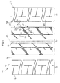
- Fig. 1 illustrates a pneumatic tire 10 according to the present exemplary embodiment, including: land portions 21, 22 provided at a tread 12 and segmented by circumferential main grooves 14, 15 extending along a tire circumferential direction and lateral main grooves 16 extending in a direction intersecting with the circumferential main groove 14 and opening onto the circumferential main grooves 14; and intersection portions 18 provided at the tread 12 at end portions where the lateral main grooves 16 open onto the circumferential main grooves 14 and a first land portion 21 and a second land portion 22 adjacent to each other in the tire circumferential direction intersect with the lateral main grooves 16, such that the first land portion 21 and the second land portion 22 support each other in the tire width direction.
- the lateral main grooves 16 open onto the circumferential main grooves 14 means that communication between the lateral main grooves 16 and the circumferential main grooves 14 is secured when in ground contact.
- the circumferential main groove 15 is for example a single groove positioned on the tire equatorial plane CL.
- the circumferential main grooves 14 are positioned in the tire width direction between the circumferential main groove 15 and the ground contact edge T.
- the lateral main grooves 16 extend at an angle to the tire width direction.
- the first land portions 21 and the second land portions 22 are configured in a central land portion region 30 in the vicinity of the tire equatorial plane CL. Shoulder land portion regions 32 are also provided at the tread 12 at positions further to the tire width direction outside than the central land portion region 30.
- the ground contact edge T is defined as the outermost edge in the tire width direction when the pneumatic tire 10 is mounted to a standard rim, as defined in the JATMA YEAR BOOK (2009 edition, Japan Automobile Tire Manufacturers Association standards), inflated to an internal pressure of 100% of the air pressure (maximum pressure) corresponding to maximum load capability (load shown in bold type in the internal pressure - load capability chart) in the JATMAYEAR BOOK for the applicable size/ply rating, and loaded to the maximum load capability.
- maximum pressure maximum pressure
- maximum load capability load shown in bold type in the internal pressure - load capability chart
- JATMAYEAR BOOK for the applicable size/ply rating
- the width WL of the lateral main grooves 16 is for example 5% to 60% of the width WR of the circumferential main grooves 14.
- the lower limit to the WL/WR percentage is set at 5% since the groove volume is reduced and water discharge performance deteriorate significantly below this level.
- the upper limit is set at 60% since the rigidity falls and the steering stability performance deteriorates above this level.
- a high level of both wet weather performance and steering stability performance can be achieved by appropriately setting the proportion of the width WL of the lateral main grooves 16 with respect to the width WR of the circumferential main grooves 14 in this manner.
- a depth D1 of the lateral main grooves 16 at the intersection portions 18 is for example 10% to 90% of a depth D2 of the lateral main grooves 16 at locations other than at the intersection portions 18.
- the lower limit of the percentage of D1/D2 is set at 10% since the groove volume inside the lateral main groove 16 decreases and water discharge performance deteriorates below this level.
- the upper limit is set at 90% since the rigidity falls and steering stability performance deteriorates above this level. Both water discharge performance in the lateral main groove 16 and steering stability performance can be achieved by appropriately setting the proportion of the depth D1 of the lateral main grooves 16 at the intersection portions 18 with respect to the depth D2 of the lateral main grooves 16 at locations other than at the intersection portions 18 on this manner.
- each of the first land portions 21 is positioned on an acute angle side of the intersection angle at the intersection portions 18 between the circumferential main groove 14 and the lateral main groove 16.
- Each of the second land portions 22 is positioned on an obtuse angle side of the intersection angle, and extends between the first land portion 21 and the circumferential main groove 14.
- the first land portion 21 and the second land portion 22 are connected at the intersection portion 18.
- Reference here to "connected” means that the first land portion 21 and the second land portion 22 are integrally formed and not separated at their boundary 26. There are accordingly no such features as sipes or fine grooves formed at the boundary 26.
- a first sloping face 21A is formed at the first land portion 21, sloping in a tread depth direction towards the second land portion 22 side.
- a second sloping face 22A ( Fig. 3C ) formed at the second land portion 22, sloping in the tread depth direction towards the first land portion 21 side, and intersecting with the first sloping face 21A as viewed from an extension direction of the lateral main groove 16 (the arrow 3C direction in Fig. 3A ).
- the first sloping face 21A and the second sloping face 22A configure groove walls of the lateral main groove 16 at the intersection portion 18.
- the parallel narrow lines on the first land portion 21 indicate the first sloping face 21A
- the parallel narrow lines on the second land portion 22 indicate the second sloping face 22A.
- the first sloping face 21A is formed as far as regions other than the intersection portion 18, and configures a groove wall of the lateral main groove 16.
- a single fine groove 28 is for example formed to the central land portion region 30 so as to extend in the tire circumferential direction.
- the first sloping face 21 A ends at the position of the fine groove 28 on the tire equatorial plane CL side.
- the lateral main grooves 16 are provided in a range between the fine groove 28 and the circumferential main grooves 14.
- the boundary 26 of the first land portion 21 and the second land portion 22 curves so as to be convex on the second land portion 22 side.
- a first end 26A of the boundary 26 ends on contact with a side portion of the first land portion 21 (the groove wall of the circumferential main grooves 14).
- a second end 26B of the extension line of the boundary 26 crosses the intersection portion 18, and contacts a side wall 22B of the second land portion 22, and continuous as the side wall 22B.
- a state is accordingly achieved in which the second sloping face 22A of the second land portion 22 extends between the first land portion 21 and the circumferential main groove 14.
- the slope angle ⁇ 1 of the first sloping face 21A with respect to a tire radial direction R is for example 0° to 60°.
- the lower limit of the slope angle ⁇ 1 is set as 0° since the groove volume of the lateral main groove 16 is reduced and water discharge performance deteriorates below this level.
- the upper limit is set at 60° since rigidity falls and steering stability performance deteriorates above this level.
- the slope angle ⁇ 2 of the second sloping face 22A with respect to the tire radial direction R is for example set at 10° to 80°.
- the lower limit of the slope angle ⁇ 2 is set as 10° since below this level tilting over of the first land portion 21 (the obtuse angle side land portion) becomes large when imparted with a large slip angle.
- the upper limit is set as 80° since the water discharge performance from the lateral main groove 16 to the circumferential main groove 14 deteriorates above this limit.
- the groove walls configuring the lateral main grooves 16 at locations other than at the intersection portions 18 are the first sloping face 21A and the side wall 22B on the first land portion 21 side of the second land portions 22.
- the side walls 22B are for example substantially parallel to the tire radial direction R.
- the angle of the lateral main grooves 16 at locations other than at the intersection portions 18 is accordingly asymmetrical about the tire radial direction R, as illustrated in Fig. 3B .
- the side wall 22B may however be configured as a sloping face such that the side wall 22B and the first sloping face 21 A are symmetrical.
- sipes 24 are formed in the bottom portion of the lateral main grooves 16 at locations other than at the intersection portions 18.
- each of the boundaries 26 between the first land portions 21 and the second land portions 22 cuts across the sipe 24. This accordingly results in state in which the sipe 24 ends at the position of the boundary 26, and the sipe 24 is not formed in the intersection portion 18.
- the sipe 24 opens onto the circumferential main groove 15 positioned on the tire equatorial plane CL.
- intersection portion 18 plural of the intersection portion 18 are provided at appropriate intervals along the tire circumferential direction.
- the land portions provided with the intersection portions 18 are not limited to the central land portion region 30, and may also be provided at the shoulder land portion regions 32.
- the lateral main grooves 16 formed in the tread 12 extend in a direction intersecting with the circumferential main grooves 14 and open onto the circumferential main groove 14. Water between the tread 12 and the road surface during wet weather running is accordingly discharged to the circumferential main groove 14 through the lateral main grooves 16. The wet weather performance can therefore be secured.
- the intersection portions 18 are provided at end portions of the lateral main grooves 16 where they open onto the circumferential main grooves 14 such that the first land portion 21 and the second land portion 22 adjacent to each other in the tire circumferential direction at each of the lateral main grooves 16 intersect so as to support each other in the tire width direction.
- the end portions on the circumferential main groove 14 side of the land portions do not readily tilt over even when a large slip angle is imparted to the tire. Steering stability performance can accordingly be secured.
- the first sloping face 21 A of the first land portion 21 and the second sloping face 22A of the second land portion 22 intersect with each other, and the first sloping face 21A and the second sloping face 22A configure the side walls of the lateral main groove 16 at the intersection portion 18. Water discharge performance from the lateral main groove 16 to the circumferential main groove 14 can accordingly be secured.
- the second land portion 22 is positioned at the obtuse angle side of the intersection portion 18, and extends between the first land portion 21 positioned at the acute angle side and the circumferential main groove 14.
- the first land portion 21 positioned on the obtuse angle side is accordingly supported by the second land portion 22 positioned on the acute angle side when a large slip angle is imparted to the tire, enabling tilting over to be suppressed.
- the first land portion 21 and the second land portion 22 are connected together at the intersection portion 18, and so the land portion rigidity at the intersection portion 18 is high, resulting in an even higher tilting over suppression effect.
- the first land portion 21 and the second land portion 22 support each other in the tire width direction, and hence tilting over of the end portions on the circumferential main groove 14 side of the land portions 21, 22 can be suppressed, enabling steering stability performance to be secured.
- the second land portion 22 includes the second sloping face 22A at the intersection portion 18, and so uneven wearing of the second land portion 22 at the intersection portion 18 is also suppressed.
- the groove wall angle of the lateral main groove 16 is asymmetrical, and so localized low rigidity at the end portion of the lateral main groove 16 (the intersection portion 18) can be reinforced whilst maintaining ground contact surface area at the second land portion 22. Note that when the first land portion 21 and the second land portion 22 are sloped in the opposite directions thereto at the end portion of the lateral main groove 16, as long as they are supporting each other both water discharge performance and land portion rigidity can be achieved irrespective of whether or not the groove wall angle of the lateral main groove 16 is symmetrical.
- the pneumatic tire 10 according to the present exemplary embodiment is thus able to achieve both wet weather performance and steering stability performance.
- the rotation direction of the pneumatic tire 10 is not limited to a single direction.
- the first land portion 21 is positioned on the acute angle side of the intersection angle between the circumferential main groove 14 and the lateral main groove 16 at the intersection portion 18, and the second land portion 22 is positioned at the obtuse angle side of the intersection angle.
- this is merely an expression of the positional relationship between the land portions 21, 22 adjacent to each other at each of the lateral main grooves 16, when looking at each of the respective lateral main grooves 16.
- one tire circumferential direction end portion is positioned on the acute angle side, however the other end portion is positioned on the obtuse angle side.
- one tire circumferential direction end portion is also positioned on the acute angle side and the other end portion on the acute angle side.
- the first sloping face 21A is formed at the first land portion 21, and the second sloping face 22A is formed at the second land portion 22, however there is no limitation thereto.
- a structure not formed with the first sloping face 21 A or the second sloping face 22A may be employed as long as the lateral main grooves 16 open onto the circumferential main groove 14, and there are intersection portions 18 where the first land portion 21 and the second land portion 22 support each other in the tire width direction.
- the lateral main grooves 16 are set at an angle with respect to the tire width direction there is no limitation thereto and the lateral main grooves 16 may be configured parallel to the tire width direction. In such cases, the rigidities at the end portion on the circumferential main groove 14 side of a given lateral main groove 16 are the same as each other, and so selection may be made as to which of the land portions adjacent at the lateral main groove 16 is the first land portion 21 and which is the second land portion 22.
- Configuration here is made such that the first land portions 21 and the second land portions 22 are connected at the intersection portions 18, however there is no limitation thereto.
- a sipe or the like may be provided at the boundary 26 between the first land portion 21 and the second land portion 22 (not shown in the drawings).
- the cross-sectional profiles of the first sloping face 21 A and the second sloping face 22A may also be a circular arc profile, a bent line profile, a stepped profile or any combination thereof.
- the boundary 26 between the first land portion 21 and the second land portion 22 here is curved so as to be convex on the second land portion 22 side, however the profile of the boundary 26 is not limited thereto.
- Numerical ranges are indicated in relation to each of the dimensions for the width WL and the depth D1 of the lateral main groove 16 at the intersection portion 18, the slope angle ⁇ 1 of the first sloping face 21A and the slope angle ⁇ 2 of the second sloping face 22A of the lateral main groove 16 at the intersection portion 18, however these indicate preferably conditions, and some or all of these dimensions may be set outside of these numerical ranges.
- a pneumatic tire 100 includes land portions (first land portions 21 and second land portions 22) that are provided at a tread 12 and segmented by circumferential main grooves 14, 15 extending along a tire circumferential direction and lateral main grooves 16 extending in a direction intersecting with the circumferential main grooves 14 and opening onto the circumferential main grooves 14, and raised bottom portions 118 that are also provided at the tread 12.
- the raised bottom portions 118 are each integrally provided at the end portion of the lateral main groove 16 where the lateral main groove 16 opens onto the circumferential main groove 14, continuously between one of the first land portions 21 and one of the second land portions 22 that are adjacent to each other in the tire circumferential direction at each of the lateral main grooves 16.
- the raised bottom portions 118 are formed by top faces forming the bottom surface of the lateral main grooves 16 configured as sloping faces that each slope in the tread depth direction as the top faces extend out respectively from the first land portion 21 and the second land portion 22. These sloping faces are referred to as a first sloping face 21A and a second sloping face 22A, described later.
- the circumferential main groove 15 is a single groove positioned for example on the tire equatorial plane CL.
- the circumferential main grooves 14 are positioned in the tire width direction between the circumferential main groove 15 and ground contact edges T.
- the first land portion 21 and the second land portion 22 extend at an angle to the tire width direction.
- the first land portion 21 and the second land portion 22 are configured in the central land portion region 30 near to the tire equatorial plane CL. Shoulder land portion regions 32 are also provided at the tread 12 at positions further to the tire width direction outside than the central land portion region 30.
- the ground contact edge T is defined as the outermost edge in the tire width direction when the pneumatic tire 10 is mounted to a standard rim, as defined in the JATMA YEAR BOOK (2011 edition, Japan Automobile Tire Manufacturers Association standards), inflated to an internal pressure of 100% of the air pressure (maximum pressure) corresponding to maximum load capability (load shown in bold type in the internal pressure - load capability chart) in the JATMA YEAR BOOK for the applicable size/ply rating, and loaded to the maximum load capability.
- maximum pressure maximum pressure
- maximum load capability load shown in bold type in the internal pressure - load capability chart
- each of the first land portions 21 is positioned on the acute angle side (the angle ⁇ side) of the intersection angle between the circumferential main groove 14 and the lateral main groove 16 at the raised bottom portions 118.
- Each of the second land portions 22 is disposed on the obtuse angle side (the angle ⁇ side) of the intersection angle.
- at the raised bottom portions 118 there is overlap in the tire width direction at side walls 21C, 22C extending respectively from the first land portion 21 and the second land portion 22.
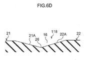
- the first land portions 21 and the second land portions 22 are connected together at the intersection portion 18 (see Fig. 6D ).
- Reference here to "connected” means that the first land portion 21 and the second land portion 22 are integrally formed and not separated at their boundary 26. There are accordingly no such features as sipes or fine grooves formed at the boundary 26.
- a side wall 21C is not a location appearing as a profile.
- the first sloping face 21A is formed at the first land portion 21 as a sloping face configuring a top face of the raised bottom portion 118 and sloping in the tread depth direction towards the second land portion 22 side.
- the second sloping face 22A is also formed at the second land portion 22 as a sloping face configuring a top face of the raised bottom portion 118 and sloping in the tread depth direction towards the first land portion 21 side (see Fig. 6C ).
- the first sloping face 21 A and the second sloping face 22A intersect with each other in the tire circumferential direction as viewed from the lateral main groove 16 extension direction (see Fig. 6D ).
- the first sloping face 21A and the second sloping face 22A configure the bottom surface of the lateral main groove 16 at the raised bottom portion 118.
- the curved narrow lines on the first land portion 21 indicate the first sloping face 21A
- the parallel narrow lines on the second land portion 22 indicate the second sloping face 22A.
- These narrow lines each represent a line of equal height with respect to the tread surface
- the first sloping face 21A has a curved face profile (for example a circular conical face profile) at the acute angle end of the first land portion 21 (not shown in the drawings) so as to form a beveled location.
- the second sloping face 22A has a flat plane profile.
- ribs 110 are provided at the tread 12, extending in the tire circumferential direction and positioned in the tire width direction adjacent to the first land portions 21 and the second land portions 22 in the tire width direction.
- the ribs 110 are provided between the first land portions 21 and the second land portions 22 and a circumferential main groove 15 positioned on the tire equatorial plane CL.
- the ribs 110 are adjacent on the tire width direction opposite side of the raised bottom portion 118 with respect to the first land portions 21 and the second land portions 22.
- a circumferential sipe 128 formed so as to be shallower than the lateral main grooves 16 is provided between each of the ribs 110 and the first land portions 21 and the second land portions 22.
- the width of the circumferential sipe 128 is 1mm and the depth is 2mm, in contrast to a width of the lateral main grooves 16 of 2mm and a depth of 8mm.
- the first land portion 21 and the second land portion 22 are effectively a single unit with the rib 110.
- the lateral main grooves 16 end at the position of the circumferential sipe 128 on the tire equatorial plane CL side.
- each of the lateral main grooves 16 is provided in a range between the circumferential sipe 128 and the circumferential main groove 14, and the raised bottom portion 118 is provided at the end portion that opens onto the circumferential main groove 14.
- the boundary 26 between the first land portion 21 and the second land portion 22 is curved so as to be convex on the second land portion 22 side.
- a first end 26A of the boundary 26 ends on contact with a groove wall of the circumferential main groove 14.
- a second end 26B of the extension line of the boundary 26 crosses the intersection portion 18, and contacts a side wall 22B of the second land portion 22, and continuous as the side wall 22B.
- the groove walls configuring the lateral main grooves 16 at locations other than at the intersection portions 18 are each configured by a side wall 21B of the first land portion 21 and a side wall 22B of the second land portion 22 facing the side wall 21B.
- plural of the raised bottom portions 118 are provided at appropriate intervals in the tire circumferential direction.
- the land portion where the raised bottom portions 118 are provided is not limited to the central land portion region 30 and provision may also be made in the shoulder land portion regions 32.
- the lateral main grooves 16 are formed in the tread 12, and the lateral main grooves 16 are set at an angle to the tire width direction.
- the lateral main grooves 16 also extend in a direction intersecting with the circumferential main grooves 14 and open onto the circumferential main groove 14.
- the raised bottom portions 118 are further provided at the end portions of the lateral main groove 16 where the lateral main grooves 16 open onto the circumferential main groove 14.
- the top faces of the raised bottom portions 118 are formed as sloping faces (the first sloping face 21A and the second sloping face 22A) that respectively slope in the tread depth direction as they extend out respectively from the first land portion 21 and the second land portion 22. Namely, an opening from the lateral main grooves 16 towards the circumferential main groove 14 is secured. Water between the tread and the road surface during wet weather running is accordingly discharged through the lateral main grooves 16 to the circumferential main grooves. Good wet weather performance (in particular braking performance) can therefore be secured.
- the raised bottom portions 118 are integrally provided at the end portions of the lateral main grooves 16 where the lateral main grooves 16 open onto the circumferential main groove 14, so as to connect between the first land portion 21 and the second land portion 22, and each of the top faces of the raised bottom portions 118 is formed by the sloping faces described above (the first sloping face 21A and the second sloping face 22A). Localized stretching of the end portions of the land portions and localized abrasion against the road surface therefore does not readily occur during ground contact of the tread 12. The uneven wear resistance performance can accordingly be raised.
- the raised bottom portions 118 do not make ground contact due to provision of the first sloping face 21 A and the second sloping face 22A to each of the raised bottom portions 118.
- the first sloping face 21 A is at a location where the acute angle end (not shown in the drawings) of the first land portion 21 is beveled with a curved face profile, and so the acute angle end can be suppressed from making ground contact.
- the durability of the end portions of the land portions is accordingly raised.
- the first sloping face 21 A and the second sloping face 22A also intersect with the tire circumferential direction as viewed from the lateral main groove 16 extension direction, and the raised bottom portions 118 are configured with the side walls 21C, 22C that extend out respectively from the land portions 21 and the second land portions 22 overlapping with each other in the tire width direction.
- the raised bottom portions 118 can accordingly support each other against force input in the tire width direction.
- the end portions on the acute angle side of the land portions accordingly do not readily tilt over when the tire is imparted with a large slip angle.
- the second sloping face 22A extending from the second land portion 22 positioned on the acute angle side extends between the first land portion 21 positioned on the obtuse angle side and the circumferential main groove 14.
- the first land portion 21 positioned on the acute angle side is therefore supported by the second land portion 22 positioned on the obtuse angle side when a large slip angle is imparted to the tire, enabling tilting of the first land portion 21 towards the circumferential main groove 14 side to be suppressed.
- the uneven wear resistance performance can accordingly be raised.
- the rotation direction of the pneumatic tire 10 is not limited to a single direction.
- the first land portion 21 is positioned on the acute angle side of the intersection angle between the circumferential main groove 14 and the lateral main groove 16 at the raised bottom portion 118
- the second land portion 22 is positioned at obtuse angle side of the intersection angle.
- this is merely an expression of the positional relationship between the land portions 21, 22 adjacent at a lateral main groove 16, when looking at each of the respective lateral main grooves 16.
- the end portion in one tire circumferential direction is positioned on the obtuse angle side, however the other end portion is positioned on the obtuse angle side.
- one end portion in the tire circumferential direction is also positioned on the acute angle side and the other end portion on the acute angle side.
- the lateral main groove 16 is set at an angle to the tire width direction, however there is no limitation thereto, and the lateral main grooves 16 may be made parallel to the tire width direction. In such cases, the rigidities at the end portion on the circumferential main groove 14 side of a given lateral main groove 16 are the same as each other, and so selection may be made as to which of the land portions adjacent at the lateral main groove 16 is the first land portion 21 and which is the second land portion 22.
- the second land portions 22 positioned on the obtuse angle side extend between the first land portions 21 positioned on the obtuse angle side and the circumferential main groove 14, however there is no limitation thereto.
- configuration may be made such that the first land portions 21 extend between the second land portion 22 and the circumferential main groove 14.
- the first land portion 21 and the second land portion 22 are integrally provided so as to be connected at the raised bottom portions 118. Mutual support is achievable even in such a placement against force input to each of the land portions in the tire width direction.
- the ribs 110 and the circumferential sipes 128 are also provided between the first land portions 21 and the second land portions 22 and the circumferential main groove 15 positioned on the tire equatorial plane CL, however there is no limitation thereto.
- a structure may also be employed without the ribs 110 and the circumferential sipes 128.
- the cross-sectional profile of the first sloping face 21A and the second sloping face 22A may also be a circular arc profile, a bent line profile, a stepped profile, or a combination thereof.
- the boundary 26 between the first land portion 21 and the second land portion 22 here is curved so as to be convex on the second land portion 22 side, however the profile of the boundary 26 is not limited thereto.
- a durability test and three types of vehicle test to confirm wet weather performance are performed for an Example according to the second exemplary embodiment, and for Comparative Examples 1, 2.
- the Example and the Comparative Examples 1, 2 differ in the profile of the top face of the raised bottom portion.
- a sloped face is not formed to the top face in the Comparative Example 1, and instead there is a simple raised bottom portion with a height of 5mm to 6mm from the groove bottom of the lateral main groove.
- a sloped face is not formed to the top face, and instead there is a raised bottom portion with a top face that is in the same plane as the tread surface, such that the lateral main grooves are not in communication with the circumferential main grooves.
- the tire size is 205/55R16, internal pressure is 230kPa, and loading is equivalent to two occupants in the vehicle.
- the test results are illustrated in Table 1.
- a drum test rig is employed for the durability test, plural test runs equivalent to 2500km travel are performed, and tires in which defects occur at in the vicinity of the corners of the land portions around the raised bottom portion are denoted by G, and when no defects occur are indicated by NG.
- evaluation is made by a test driver of the feeling at the limiting speed at which hydroplaning occurs when running on a wet road with a water depth of 5mm.
- NG indicates that a professional test driver feels a meaningful drop in the level of performance in comparison to the Example.
- evaluation is made by a test driver of the feeling during a cornering test when running on a wet road with a water depth of 5mm. NG indicates that a professional test driver feels a meaningful drop in the level of performance in comparison to the Example
- evaluation is made by a test driver of the feeling of the braking effectiveness when running in various running modes on a circuit course in wet conditions.
- NG indicates that a professional test driver feels a meaningful drop in the level of performance in comparison to the Example
Landscapes
- Engineering & Computer Science (AREA)
- Mechanical Engineering (AREA)
- Tires In General (AREA)
Applications Claiming Priority (3)
| Application Number | Priority Date | Filing Date | Title |
|---|---|---|---|
| JP2010188378A JP5975597B2 (ja) | 2010-08-25 | 2010-08-25 | 空気入りタイヤ |
| JP2011183308A JP5762216B2 (ja) | 2011-08-25 | 2011-08-25 | 空気入りタイヤ |
| PCT/JP2011/069218 WO2012026545A1 (fr) | 2010-08-25 | 2011-08-25 | Pneu |
Publications (3)
| Publication Number | Publication Date |
|---|---|
| EP2610083A1 true EP2610083A1 (fr) | 2013-07-03 |
| EP2610083A4 EP2610083A4 (fr) | 2014-07-16 |
| EP2610083B1 EP2610083B1 (fr) | 2015-10-07 |
Family
ID=45723536
Family Applications (1)
| Application Number | Title | Priority Date | Filing Date |
|---|---|---|---|
| EP11820008.8A Not-in-force EP2610083B1 (fr) | 2010-08-25 | 2011-08-25 | Pneu |
Country Status (4)
| Country | Link |
|---|---|
| US (1) | US9387729B2 (fr) |
| EP (1) | EP2610083B1 (fr) |
| CN (1) | CN103097149B (fr) |
| WO (1) | WO2012026545A1 (fr) |
Families Citing this family (12)
| Publication number | Priority date | Publication date | Assignee | Title |
|---|---|---|---|---|
| CN104349914B (zh) | 2012-06-19 | 2016-11-09 | 株式会社普利司通 | 轮胎 |
| JP5781566B2 (ja) | 2013-07-10 | 2015-09-24 | 株式会社ブリヂストン | 空気入りタイヤ |
| JP6605459B2 (ja) * | 2014-05-29 | 2019-11-13 | 株式会社ブリヂストン | 空気入りタイヤ |
| JP6518660B2 (ja) * | 2014-05-29 | 2019-05-22 | 株式会社ブリヂストン | 空気入りタイヤ |
| JP6306436B2 (ja) * | 2014-05-30 | 2018-04-04 | 株式会社ブリヂストン | 空気入りタイヤ |
| JP6393208B2 (ja) * | 2015-02-16 | 2018-09-19 | 住友ゴム工業株式会社 | 空気入りタイヤ |
| JP6405284B2 (ja) * | 2015-04-17 | 2018-10-17 | 住友ゴム工業株式会社 | 空気入りタイヤ |
| JP6605849B2 (ja) * | 2015-06-12 | 2019-11-13 | 株式会社ブリヂストン | タイヤ |
| USD792330S1 (en) * | 2015-08-31 | 2017-07-18 | Nokian Tyres Plc | Tyre |
| JP2017052329A (ja) * | 2015-09-07 | 2017-03-16 | 株式会社ブリヂストン | 乗用車用空気入りタイヤ |
| USD779414S1 (en) * | 2015-09-16 | 2017-02-21 | Shandong Hongsheng Rubber Co., Ltd. | Tyre |
| WO2017187960A1 (fr) | 2016-04-28 | 2017-11-02 | 株式会社ブリヂストン | Pneumatique |
Family Cites Families (16)
| Publication number | Priority date | Publication date | Assignee | Title |
|---|---|---|---|---|
| JP2632937B2 (ja) | 1988-07-01 | 1997-07-23 | 株式会社ブリヂストン | 空気入りタイヤ |
| JPH0220407A (ja) | 1988-07-09 | 1990-01-24 | Sumitomo Rubber Ind Ltd | 重車両用ラジアルタイヤ |
| JPH04201607A (ja) | 1990-11-30 | 1992-07-22 | Bridgestone Corp | 空気入りタイヤ |
| JP3203057B2 (ja) * | 1992-07-28 | 2001-08-27 | 住友ゴム工業株式会社 | 空気入りタイヤ |
| JP4559638B2 (ja) * | 1999-02-26 | 2010-10-13 | 株式会社ブリヂストン | 空気入りタイヤ |
| JP4350204B2 (ja) | 1999-05-14 | 2009-10-21 | 株式会社ブリヂストン | 空気入りタイヤ |
| JP4331345B2 (ja) * | 1999-09-08 | 2009-09-16 | 株式会社ブリヂストン | 方向性パターンを有する空気入りタイヤ |
| JP4369001B2 (ja) * | 2000-02-17 | 2009-11-18 | 株式会社ブリヂストン | 方向性パターンを有する空気入りタイヤ |
| JP3894777B2 (ja) | 2001-11-16 | 2007-03-22 | 横浜ゴム株式会社 | 空気入りタイヤ |
| JP4133147B2 (ja) | 2002-09-11 | 2008-08-13 | 株式会社ブリヂストン | 空気入りタイヤ |
| JP4581732B2 (ja) | 2005-02-16 | 2010-11-17 | 横浜ゴム株式会社 | 空気入りタイヤ |
| JP4776523B2 (ja) * | 2006-12-20 | 2011-09-21 | 株式会社ブリヂストン | 空気入りタイヤ |
| KR101096990B1 (ko) | 2006-12-20 | 2011-12-20 | 가부시키가이샤 브리지스톤 | 공기입 타이어 |
| JP4869089B2 (ja) * | 2007-01-22 | 2012-02-01 | 株式会社ブリヂストン | 空気入りタイヤ |
| JP5073568B2 (ja) * | 2008-04-23 | 2012-11-14 | 東洋ゴム工業株式会社 | 空気入りタイヤ |
| JP4329912B1 (ja) | 2009-03-16 | 2009-09-09 | 横浜ゴム株式会社 | 空気入りタイヤ |
-
2011
- 2011-08-25 CN CN201180040840.5A patent/CN103097149B/zh not_active Expired - Fee Related
- 2011-08-25 US US13/817,727 patent/US9387729B2/en active Active
- 2011-08-25 EP EP11820008.8A patent/EP2610083B1/fr not_active Not-in-force
- 2011-08-25 WO PCT/JP2011/069218 patent/WO2012026545A1/fr active Application Filing
Non-Patent Citations (2)
| Title |
|---|
| No further relevant documents disclosed * |
| See also references of WO2012026545A1 * |
Also Published As
| Publication number | Publication date |
|---|---|
| CN103097149A (zh) | 2013-05-08 |
| US9387729B2 (en) | 2016-07-12 |
| EP2610083B1 (fr) | 2015-10-07 |
| WO2012026545A1 (fr) | 2012-03-01 |
| EP2610083A4 (fr) | 2014-07-16 |
| US20130146190A1 (en) | 2013-06-13 |
| CN103097149B (zh) | 2015-11-25 |
Similar Documents
| Publication | Publication Date | Title |
|---|---|---|
| EP2610083B1 (fr) | Pneu | |
| EP3260308B1 (fr) | Pneumatique | |
| EP3498498B1 (fr) | Pneumatique | |
| EP3147139B1 (fr) | Pneumatique | |
| EP3178668B1 (fr) | Pneumatique | |
| EP2952362B1 (fr) | Pneumatique | |
| EP3056359B1 (fr) | Pneumatique | |
| EP3263367B1 (fr) | Pneumatique | |
| EP3095622B1 (fr) | Pneumatique | |
| EP3093162B1 (fr) | Pneumatique | |
| EP2610086B1 (fr) | Pneu | |
| EP2390113B1 (fr) | Pneu | |
| EP2732982B1 (fr) | Pneu | |
| EP3093163B1 (fr) | Pneu | |
| EP3135504B1 (fr) | Pneu pour poids lourds | |
| JP5177180B2 (ja) | 空気入りタイヤ | |
| EP2692543B1 (fr) | Pneumatique | |
| EP3572243B1 (fr) | Pneumatique | |
| EP2610084B1 (fr) | Pneu | |
| EP2127910A1 (fr) | Pneu | |
| EP3470243A1 (fr) | Pneumatique | |
| EP3822093B1 (fr) | Pneumatique | |
| CN113905899B (zh) | 充气轮胎 | |
| CN113891808B (zh) | 充气轮胎 | |
| CN110001297B (zh) | 充气轮胎 |
Legal Events
| Date | Code | Title | Description |
|---|---|---|---|
| PUAI | Public reference made under article 153(3) epc to a published international application that has entered the european phase |
Free format text: ORIGINAL CODE: 0009012 |
|
| 17P | Request for examination filed |
Effective date: 20130208 |
|
| AK | Designated contracting states |
Kind code of ref document: A1 Designated state(s): AL AT BE BG CH CY CZ DE DK EE ES FI FR GB GR HR HU IE IS IT LI LT LU LV MC MK MT NL NO PL PT RO RS SE SI SK SM TR |
|
| DAX | Request for extension of the european patent (deleted) | ||
| A4 | Supplementary search report drawn up and despatched |
Effective date: 20140617 |
|
| RIC1 | Information provided on ipc code assigned before grant |
Ipc: B60C 11/13 20060101ALI20140611BHEP Ipc: B60C 11/11 20060101ALI20140611BHEP Ipc: B60C 11/12 20060101ALI20140611BHEP Ipc: B60C 11/04 20060101AFI20140611BHEP |
|
| GRAP | Despatch of communication of intention to grant a patent |
Free format text: ORIGINAL CODE: EPIDOSNIGR1 |
|
| INTG | Intention to grant announced |
Effective date: 20150421 |
|
| GRAS | Grant fee paid |
Free format text: ORIGINAL CODE: EPIDOSNIGR3 |
|
| GRAA | (expected) grant |
Free format text: ORIGINAL CODE: 0009210 |
|
| AK | Designated contracting states |
Kind code of ref document: B1 Designated state(s): AL AT BE BG CH CY CZ DE DK EE ES FI FR GB GR HR HU IE IS IT LI LT LU LV MC MK MT NL NO PL PT RO RS SE SI SK SM TR |
|
| REG | Reference to a national code |
Ref country code: GB Ref legal event code: FG4D |
|
| REG | Reference to a national code |
Ref country code: AT Ref legal event code: REF Ref document number: 753512 Country of ref document: AT Kind code of ref document: T Effective date: 20151015 Ref country code: CH Ref legal event code: EP |
|
| REG | Reference to a national code |
Ref country code: IE Ref legal event code: FG4D |
|
| REG | Reference to a national code |
Ref country code: DE Ref legal event code: R096 Ref document number: 602011020413 Country of ref document: DE |
|
| REG | Reference to a national code |
Ref country code: NL Ref legal event code: MP Effective date: 20151007 |
|
| REG | Reference to a national code |
Ref country code: AT Ref legal event code: MK05 Ref document number: 753512 Country of ref document: AT Kind code of ref document: T Effective date: 20151007 |
|
| REG | Reference to a national code |
Ref country code: LT Ref legal event code: MG4D |
|
| PG25 | Lapsed in a contracting state [announced via postgrant information from national office to epo] |
Ref country code: NL Free format text: LAPSE BECAUSE OF FAILURE TO SUBMIT A TRANSLATION OF THE DESCRIPTION OR TO PAY THE FEE WITHIN THE PRESCRIBED TIME-LIMIT Effective date: 20151007 Ref country code: IS Free format text: LAPSE BECAUSE OF FAILURE TO SUBMIT A TRANSLATION OF THE DESCRIPTION OR TO PAY THE FEE WITHIN THE PRESCRIBED TIME-LIMIT Effective date: 20160207 Ref country code: HR Free format text: LAPSE BECAUSE OF FAILURE TO SUBMIT A TRANSLATION OF THE DESCRIPTION OR TO PAY THE FEE WITHIN THE PRESCRIBED TIME-LIMIT Effective date: 20151007 Ref country code: LT Free format text: LAPSE BECAUSE OF FAILURE TO SUBMIT A TRANSLATION OF THE DESCRIPTION OR TO PAY THE FEE WITHIN THE PRESCRIBED TIME-LIMIT Effective date: 20151007 Ref country code: ES Free format text: LAPSE BECAUSE OF FAILURE TO SUBMIT A TRANSLATION OF THE DESCRIPTION OR TO PAY THE FEE WITHIN THE PRESCRIBED TIME-LIMIT Effective date: 20151007 Ref country code: NO Free format text: LAPSE BECAUSE OF FAILURE TO SUBMIT A TRANSLATION OF THE DESCRIPTION OR TO PAY THE FEE WITHIN THE PRESCRIBED TIME-LIMIT Effective date: 20160107 |
|
| PG25 | Lapsed in a contracting state [announced via postgrant information from national office to epo] |
Ref country code: SE Free format text: LAPSE BECAUSE OF FAILURE TO SUBMIT A TRANSLATION OF THE DESCRIPTION OR TO PAY THE FEE WITHIN THE PRESCRIBED TIME-LIMIT Effective date: 20151007 Ref country code: FI Free format text: LAPSE BECAUSE OF FAILURE TO SUBMIT A TRANSLATION OF THE DESCRIPTION OR TO PAY THE FEE WITHIN THE PRESCRIBED TIME-LIMIT Effective date: 20151007 Ref country code: PL Free format text: LAPSE BECAUSE OF FAILURE TO SUBMIT A TRANSLATION OF THE DESCRIPTION OR TO PAY THE FEE WITHIN THE PRESCRIBED TIME-LIMIT Effective date: 20151007 Ref country code: RS Free format text: LAPSE BECAUSE OF FAILURE TO SUBMIT A TRANSLATION OF THE DESCRIPTION OR TO PAY THE FEE WITHIN THE PRESCRIBED TIME-LIMIT Effective date: 20151007 Ref country code: LV Free format text: LAPSE BECAUSE OF FAILURE TO SUBMIT A TRANSLATION OF THE DESCRIPTION OR TO PAY THE FEE WITHIN THE PRESCRIBED TIME-LIMIT Effective date: 20151007 Ref country code: PT Free format text: LAPSE BECAUSE OF FAILURE TO SUBMIT A TRANSLATION OF THE DESCRIPTION OR TO PAY THE FEE WITHIN THE PRESCRIBED TIME-LIMIT Effective date: 20160208 Ref country code: GR Free format text: LAPSE BECAUSE OF FAILURE TO SUBMIT A TRANSLATION OF THE DESCRIPTION OR TO PAY THE FEE WITHIN THE PRESCRIBED TIME-LIMIT Effective date: 20160108 Ref country code: AT Free format text: LAPSE BECAUSE OF FAILURE TO SUBMIT A TRANSLATION OF THE DESCRIPTION OR TO PAY THE FEE WITHIN THE PRESCRIBED TIME-LIMIT Effective date: 20151007 |
|
| REG | Reference to a national code |
Ref country code: DE Ref legal event code: R097 Ref document number: 602011020413 Country of ref document: DE |
|
| PG25 | Lapsed in a contracting state [announced via postgrant information from national office to epo] |
Ref country code: CZ Free format text: LAPSE BECAUSE OF FAILURE TO SUBMIT A TRANSLATION OF THE DESCRIPTION OR TO PAY THE FEE WITHIN THE PRESCRIBED TIME-LIMIT Effective date: 20151007 |
|
| PLBE | No opposition filed within time limit |
Free format text: ORIGINAL CODE: 0009261 |
|
| STAA | Information on the status of an ep patent application or granted ep patent |
Free format text: STATUS: NO OPPOSITION FILED WITHIN TIME LIMIT |
|
| REG | Reference to a national code |
Ref country code: FR Ref legal event code: PLFP Year of fee payment: 6 |
|
| PG25 | Lapsed in a contracting state [announced via postgrant information from national office to epo] |
Ref country code: RO Free format text: LAPSE BECAUSE OF FAILURE TO SUBMIT A TRANSLATION OF THE DESCRIPTION OR TO PAY THE FEE WITHIN THE PRESCRIBED TIME-LIMIT Effective date: 20151007 Ref country code: SM Free format text: LAPSE BECAUSE OF FAILURE TO SUBMIT A TRANSLATION OF THE DESCRIPTION OR TO PAY THE FEE WITHIN THE PRESCRIBED TIME-LIMIT Effective date: 20151007 Ref country code: DK Free format text: LAPSE BECAUSE OF FAILURE TO SUBMIT A TRANSLATION OF THE DESCRIPTION OR TO PAY THE FEE WITHIN THE PRESCRIBED TIME-LIMIT Effective date: 20151007 Ref country code: SK Free format text: LAPSE BECAUSE OF FAILURE TO SUBMIT A TRANSLATION OF THE DESCRIPTION OR TO PAY THE FEE WITHIN THE PRESCRIBED TIME-LIMIT Effective date: 20151007 Ref country code: EE Free format text: LAPSE BECAUSE OF FAILURE TO SUBMIT A TRANSLATION OF THE DESCRIPTION OR TO PAY THE FEE WITHIN THE PRESCRIBED TIME-LIMIT Effective date: 20151007 |
|
| 26N | No opposition filed |
Effective date: 20160708 |
|
| PG25 | Lapsed in a contracting state [announced via postgrant information from national office to epo] |
Ref country code: SI Free format text: LAPSE BECAUSE OF FAILURE TO SUBMIT A TRANSLATION OF THE DESCRIPTION OR TO PAY THE FEE WITHIN THE PRESCRIBED TIME-LIMIT Effective date: 20151007 |
|
| PG25 | Lapsed in a contracting state [announced via postgrant information from national office to epo] |
Ref country code: BE Free format text: LAPSE BECAUSE OF FAILURE TO SUBMIT A TRANSLATION OF THE DESCRIPTION OR TO PAY THE FEE WITHIN THE PRESCRIBED TIME-LIMIT Effective date: 20151007 |
|
| PG25 | Lapsed in a contracting state [announced via postgrant information from national office to epo] |
Ref country code: MC Free format text: LAPSE BECAUSE OF FAILURE TO SUBMIT A TRANSLATION OF THE DESCRIPTION OR TO PAY THE FEE WITHIN THE PRESCRIBED TIME-LIMIT Effective date: 20151007 |
|
| REG | Reference to a national code |
Ref country code: CH Ref legal event code: PL |
|
| GBPC | Gb: european patent ceased through non-payment of renewal fee |
Effective date: 20160825 |
|
| PG25 | Lapsed in a contracting state [announced via postgrant information from national office to epo] |
Ref country code: LI Free format text: LAPSE BECAUSE OF NON-PAYMENT OF DUE FEES Effective date: 20160831 Ref country code: CH Free format text: LAPSE BECAUSE OF NON-PAYMENT OF DUE FEES Effective date: 20160831 |
|
| REG | Reference to a national code |
Ref country code: IE Ref legal event code: MM4A |
|
| PG25 | Lapsed in a contracting state [announced via postgrant information from national office to epo] |
Ref country code: IE Free format text: LAPSE BECAUSE OF NON-PAYMENT OF DUE FEES Effective date: 20160825 Ref country code: GB Free format text: LAPSE BECAUSE OF NON-PAYMENT OF DUE FEES Effective date: 20160825 |
|
| REG | Reference to a national code |
Ref country code: FR Ref legal event code: PLFP Year of fee payment: 7 |
|
| PG25 | Lapsed in a contracting state [announced via postgrant information from national office to epo] |
Ref country code: LU Free format text: LAPSE BECAUSE OF NON-PAYMENT OF DUE FEES Effective date: 20160825 |
|
| PG25 | Lapsed in a contracting state [announced via postgrant information from national office to epo] |
Ref country code: HU Free format text: LAPSE BECAUSE OF FAILURE TO SUBMIT A TRANSLATION OF THE DESCRIPTION OR TO PAY THE FEE WITHIN THE PRESCRIBED TIME-LIMIT; INVALID AB INITIO Effective date: 20110825 Ref country code: CY Free format text: LAPSE BECAUSE OF FAILURE TO SUBMIT A TRANSLATION OF THE DESCRIPTION OR TO PAY THE FEE WITHIN THE PRESCRIBED TIME-LIMIT Effective date: 20151007 |
|
| PG25 | Lapsed in a contracting state [announced via postgrant information from national office to epo] |
Ref country code: TR Free format text: LAPSE BECAUSE OF FAILURE TO SUBMIT A TRANSLATION OF THE DESCRIPTION OR TO PAY THE FEE WITHIN THE PRESCRIBED TIME-LIMIT Effective date: 20151007 Ref country code: MT Free format text: LAPSE BECAUSE OF NON-PAYMENT OF DUE FEES Effective date: 20160831 Ref country code: MK Free format text: LAPSE BECAUSE OF FAILURE TO SUBMIT A TRANSLATION OF THE DESCRIPTION OR TO PAY THE FEE WITHIN THE PRESCRIBED TIME-LIMIT Effective date: 20151007 |
|
| PG25 | Lapsed in a contracting state [announced via postgrant information from national office to epo] |
Ref country code: BG Free format text: LAPSE BECAUSE OF FAILURE TO SUBMIT A TRANSLATION OF THE DESCRIPTION OR TO PAY THE FEE WITHIN THE PRESCRIBED TIME-LIMIT Effective date: 20151007 |
|
| REG | Reference to a national code |
Ref country code: FR Ref legal event code: PLFP Year of fee payment: 8 |
|
| PG25 | Lapsed in a contracting state [announced via postgrant information from national office to epo] |
Ref country code: AL Free format text: LAPSE BECAUSE OF FAILURE TO SUBMIT A TRANSLATION OF THE DESCRIPTION OR TO PAY THE FEE WITHIN THE PRESCRIBED TIME-LIMIT Effective date: 20151007 |
|
| PGFP | Annual fee paid to national office [announced via postgrant information from national office to epo] |
Ref country code: IT Payment date: 20190829 Year of fee payment: 9 |
|
| PGFP | Annual fee paid to national office [announced via postgrant information from national office to epo] |
Ref country code: DE Payment date: 20200819 Year of fee payment: 10 Ref country code: FR Payment date: 20200821 Year of fee payment: 10 |
|
| PG25 | Lapsed in a contracting state [announced via postgrant information from national office to epo] |
Ref country code: IT Free format text: LAPSE BECAUSE OF NON-PAYMENT OF DUE FEES Effective date: 20200825 |
|
| REG | Reference to a national code |
Ref country code: DE Ref legal event code: R119 Ref document number: 602011020413 Country of ref document: DE |
|
| PG25 | Lapsed in a contracting state [announced via postgrant information from national office to epo] |
Ref country code: FR Free format text: LAPSE BECAUSE OF NON-PAYMENT OF DUE FEES Effective date: 20210831 Ref country code: DE Free format text: LAPSE BECAUSE OF NON-PAYMENT OF DUE FEES Effective date: 20220301 |