EP2607638A2 - Abgasanlage - Google Patents
Abgasanlage Download PDFInfo
- Publication number
- EP2607638A2 EP2607638A2 EP12194240.3A EP12194240A EP2607638A2 EP 2607638 A2 EP2607638 A2 EP 2607638A2 EP 12194240 A EP12194240 A EP 12194240A EP 2607638 A2 EP2607638 A2 EP 2607638A2
- Authority
- EP
- European Patent Office
- Prior art keywords
- section
- connecting tube
- exhaust system
- exhaust
- radiator
- Prior art date
- Legal status (The legal status is an assumption and is not a legal conclusion. Google has not performed a legal analysis and makes no representation as to the accuracy of the status listed.)
- Granted
Links
Images



Classifications
-
- F—MECHANICAL ENGINEERING; LIGHTING; HEATING; WEAPONS; BLASTING
- F01—MACHINES OR ENGINES IN GENERAL; ENGINE PLANTS IN GENERAL; STEAM ENGINES
- F01N—GAS-FLOW SILENCERS OR EXHAUST APPARATUS FOR MACHINES OR ENGINES IN GENERAL; GAS-FLOW SILENCERS OR EXHAUST APPARATUS FOR INTERNAL-COMBUSTION ENGINES
- F01N1/00—Silencing apparatus characterised by method of silencing
- F01N1/06—Silencing apparatus characterised by method of silencing by using interference effect
- F01N1/065—Silencing apparatus characterised by method of silencing by using interference effect by using an active noise source, e.g. speakers
-
- F—MECHANICAL ENGINEERING; LIGHTING; HEATING; WEAPONS; BLASTING
- F01—MACHINES OR ENGINES IN GENERAL; ENGINE PLANTS IN GENERAL; STEAM ENGINES
- F01N—GAS-FLOW SILENCERS OR EXHAUST APPARATUS FOR MACHINES OR ENGINES IN GENERAL; GAS-FLOW SILENCERS OR EXHAUST APPARATUS FOR INTERNAL-COMBUSTION ENGINES
- F01N3/00—Exhaust or silencing apparatus having means for purifying, rendering innocuous, or otherwise treating exhaust
- F01N3/02—Exhaust or silencing apparatus having means for purifying, rendering innocuous, or otherwise treating exhaust for cooling, or for removing solid constituents of, exhaust
- F01N3/05—Exhaust or silencing apparatus having means for purifying, rendering innocuous, or otherwise treating exhaust for cooling, or for removing solid constituents of, exhaust by means of air, e.g. by mixing exhaust with air
- F01N3/055—Exhaust or silencing apparatus having means for purifying, rendering innocuous, or otherwise treating exhaust for cooling, or for removing solid constituents of, exhaust by means of air, e.g. by mixing exhaust with air without contact between air and exhaust gases
-
- F—MECHANICAL ENGINEERING; LIGHTING; HEATING; WEAPONS; BLASTING
- F01—MACHINES OR ENGINES IN GENERAL; ENGINE PLANTS IN GENERAL; STEAM ENGINES
- F01N—GAS-FLOW SILENCERS OR EXHAUST APPARATUS FOR MACHINES OR ENGINES IN GENERAL; GAS-FLOW SILENCERS OR EXHAUST APPARATUS FOR INTERNAL-COMBUSTION ENGINES
- F01N2240/00—Combination or association of two or more different exhaust treating devices, or of at least one such device with an auxiliary device, not covered by indexing codes F01N2230/00 or F01N2250/00, one of the devices being
- F01N2240/20—Combination or association of two or more different exhaust treating devices, or of at least one such device with an auxiliary device, not covered by indexing codes F01N2230/00 or F01N2250/00, one of the devices being a flow director or deflector
-
- F—MECHANICAL ENGINEERING; LIGHTING; HEATING; WEAPONS; BLASTING
- F01—MACHINES OR ENGINES IN GENERAL; ENGINE PLANTS IN GENERAL; STEAM ENGINES
- F01N—GAS-FLOW SILENCERS OR EXHAUST APPARATUS FOR MACHINES OR ENGINES IN GENERAL; GAS-FLOW SILENCERS OR EXHAUST APPARATUS FOR INTERNAL-COMBUSTION ENGINES
- F01N2260/00—Exhaust treating devices having provisions not otherwise provided for
- F01N2260/02—Exhaust treating devices having provisions not otherwise provided for for cooling the device
- F01N2260/022—Exhaust treating devices having provisions not otherwise provided for for cooling the device using air
-
- F—MECHANICAL ENGINEERING; LIGHTING; HEATING; WEAPONS; BLASTING
- F01—MACHINES OR ENGINES IN GENERAL; ENGINE PLANTS IN GENERAL; STEAM ENGINES
- F01N—GAS-FLOW SILENCERS OR EXHAUST APPARATUS FOR MACHINES OR ENGINES IN GENERAL; GAS-FLOW SILENCERS OR EXHAUST APPARATUS FOR INTERNAL-COMBUSTION ENGINES
- F01N2260/00—Exhaust treating devices having provisions not otherwise provided for
- F01N2260/20—Exhaust treating devices having provisions not otherwise provided for for heat or sound protection, e.g. using a shield or specially shaped outer surface of exhaust device
-
- Y—GENERAL TAGGING OF NEW TECHNOLOGICAL DEVELOPMENTS; GENERAL TAGGING OF CROSS-SECTIONAL TECHNOLOGIES SPANNING OVER SEVERAL SECTIONS OF THE IPC; TECHNICAL SUBJECTS COVERED BY FORMER USPC CROSS-REFERENCE ART COLLECTIONS [XRACs] AND DIGESTS
- Y02—TECHNOLOGIES OR APPLICATIONS FOR MITIGATION OR ADAPTATION AGAINST CLIMATE CHANGE
- Y02T—CLIMATE CHANGE MITIGATION TECHNOLOGIES RELATED TO TRANSPORTATION
- Y02T10/00—Road transport of goods or passengers
- Y02T10/10—Internal combustion engine [ICE] based vehicles
- Y02T10/12—Improving ICE efficiencies
Definitions
- the present invention relates to an exhaust system for an internal combustion engine, in particular of a motor vehicle.
- An exhaust system usually comprises at least one exhaust system, which has at least one exhaust pipe leading exhaust pipe.
- the respective exhaust gas line serves for the removal of exhaust gas, which is produced in combustion chambers of the internal combustion engine.
- the exhaust system comes with a single exhaust system or comprises at least two exhaust lines, eg. In a V-engine.
- exhaust aftertreatment devices are arranged, such.
- catalysts particulate filters, SCR systems and mufflers, which are connected to each other via exhaust pipes.
- an exhaust system usually comprises an exhaust gas collector, so-called “exhaust manifold", while an end pipe is arranged at the end, so-called “exhaust”. These end components can also be connected to exhaust pipes.
- the invention may also include properties and / or components of a passive silencer, such as at least one resonance, reflection, expansion and / or adsorption chamber.
- An active silencer may have a silencer housing and at least one arranged in the silencer housing electro-acoustic transducer and at least one connecting pipe.
- the muffler housing can be fluidly connected to the exhaust pipe. In this way, the silencer housing is connected in shunt to the exhaust line, so that it is not flowed through by the exhaust gas.
- the fluidic connection between the muffler housing and the exhaust pipe which is created by means of the connecting tube, on the other hand ensures an acoustic coupling for airborne sound, so that on the one hand the sound carried in the exhaust gas can propagate in the direction of the muffler housing, while on the other hand the generated by the electro-acoustic transducer Sound can be radiated into the exhaust pipe.
- a physical spacing between the muffler housing and the exhaust pipe is realized via the connecting pipe, as a result of which the thermal load of the converter can be reduced.
- the hot exhaust gases carried in the exhaust pipe can nevertheless lead to a high thermal load of the converter.
- the hot exhaust gas can enter the connecting pipe by diffusion processes and reach the converter.
- the exhaust gas heats the exhaust pipe, so that heat can pass through heat pipe from the exhaust pipe via the connecting pipe to the muffler housing.
- heat radiation from the exhaust gas or from the exhaust pipe can propagate through the connecting pipe to the converter.
- the connecting pipe between the muffler housing and to equip the exhaust pipe with a radiator section In this way, the connection pipe can be cooled by releasing heat to the outside over the radiator section.
- the connecting tube in the radiator section may have outwardly projecting external cooling ribs.
- a cooling jacket in the radiator section through which a coolant flows.
- this cooling jacket can be fluidically coupled to a cooling circuit of the internal combustion engine equipped with the exhaust system.
- the invention is based on the general idea, with the help of at least one internal cooling fin, which projects into the cross section of the connecting tube, to increase the thermal mass of the connecting tube, whereby the heat is delayed in time or attenuated passes from the exhaust pipe to the muffler housing. In this way, the thermal load of the transducer can be reduced.
- the active muffler Due to the reduced thermal load of the converter and possibly other electronic components in the muffler housing, it is also possible, the active muffler further upstream, closer to the internal combustion engine to arrange, as this is possible so far. A close-coupled arrangement can be advantageous for certain requirements.
- the at least one inner cooling rib in a radiator section of the connecting tube, so that the respective inner cooling rib protrudes inward in the radiator section from a radiator wall of the radiator section and projects into the cross section of the connecting tube or the radiator section.
- the respective inner cooling rib By positioning the respective inner cooling rib in the radiator section, the heat transferred to the respective inner cooling rib can be diverted from the respective inner cooling rib to a radiator wall of the radiator section which surrounds the cross section of the connecting tube in the circumferential direction and can be removed by cooling the radiator section, if required.
- the respective inner fin in the cooler section, a cooling of the respective inner fin, which improves the efficiency of the thermal protection of the transducer.
- the respective internal cooling rib contributes to increasing the thermal mass of the radiator section.
- the aforesaid cooler section may be a pipe body which is separate with respect to the connecting pipe and which is installed in a suitable manner in the connecting pipe, for example via welded connections or via flange connections.
- the connecting pipe may be made of an iron alloy or a steel alloy, while the tubular body of the radiator section is made of a light metal alloy, which is characterized by a significantly better thermal conductivity.
- the separate tubular body of the radiator section an embodiment in which the connecting tube is made on both sides of the radiator portion made of different materials.
- the connecting pipe may be made of a metallic material from the radiator section to the exhaust pipe, while it may be made of a plastic from the radiator section to the silencer housing.
- the connecting tube in a curved manner such that no straight-line radiation path extending from the exhaust pipe to the muffler housing is present through the connecting pipe.
- the connecting tube may be e.g. have a 90 ° bend or an S-bend.
- the at least one internal cooling rib in a cross-section of the connecting tube in such a way that the connecting tube remains permeable to airborne sound, while the at least one internal cooling rib closes the cross-section of the connecting tube in a perspective view in a direction parallel to the longitudinal central axis of the connecting tube ,
- the respective inside Cooling fin can thus also effectively a passage of heat radiation through the connecting pipe are prevented, while the propagation of airborne sound through the connecting pipe is largely unhindered. This also significantly reduces the thermal load on the transducer.
- the use of the at least one inner cooling rib for opaque obstruction of the airborne sound-permeable cross-section of the connecting pipe makes it possible to use a straight-line connecting pipe, which is particularly inexpensive to implement and is accordingly preferred.
- the alternative developments proposed here can also be combined with each other so that, on the one hand, a curved connecting tube is provided whose cross-section, on the other hand, is opaque in the viewing direction with the at least one inner cooling rib.
- the respective inner fin can be useful a sheet metal body, which is characterized by a high thermal conductivity and heat resistance.
- a plurality of such internal cooling fins are provided which project inwardly from a tube wall of the connecting tube or from the aforementioned cooler wall of the cooler section.
- the use of a plurality of internal cooling ribs allows an embodiment of the inner cooling rib such that they impede the airborne sound propagation along the sound propagation path only insignificantly.
- the internal cooling rib can also be formed by a perforated plate.
- Such a perforated plate can in particular be arranged so that it closes the cross section of the connecting tube or the radiator section for thermal radiation.
- the holes of the perforated plate can be formed by the provision of tabs, said tabs are expediently issued such that they obstruct the associated openings in the viewing direction.
- the respective inner cooling rib may be designed as blades, which is employed in particular with respect to the longitudinal central axis.
- Such blades which can also be referred to as guide vanes in a flow-through pipe-which is not the case here with the connecting pipe-are characterized by a comparatively low acoustic resistance, so that such blades only hinder the sound propagation path only slightly.
- a plurality of internal cooling ribs may be arranged in a star shape, resulting in a rotational symmetry for the interaction of the internal cooling ribs with the sound propagation path.
- the star-shaped inner cooling fins may be arranged radially inwardly free-standing so that they do not touch each other.
- the star-shaped inner cooling fins are supported in a common center to each other. The freestanding arrangement avoids thermally induced stresses.
- a common center allows the realization of the internal cooling fins as a unit, which can be used in the respective cross section as a separate component.
- the arrangement of the inner cooling fins can be configured like a static mixer and in particular in the form of a swirl generator. Since the connecting pipe is not flowed through by the exhaust gas, there is no mixing or swirl generation in the region of the internal cooling ribs, but in particular an opaque closure of the respective cross section with an open and largely unhindered sound propagation path.
- the respective inner cooling rib may extend at least along the radiator wall in the longitudinal direction of the connecting tube or the radiator section and in the circumferential direction.
- the sound propagation path follows a curved path, which is a negligible obstacle to sound propagation, and which is an insurmountable obstacle to straight-line radiant heat.
- a plurality of internal cooling fins may be configured as rectilinear blades, which run parallel to each other.
- the internal cooling fins can be designed as a blade grid.
- a leading edge of an inner cooling fin may overlap or are aligned with an outflow edge of an adjacent inner cooling fin in the viewing direction in the viewing direction.
- the individual inner cooling ribs each block a portion of the cross section of the connecting tube or the radiator section in the viewing direction, such that all internal cooling rib together in particular close the entire cross-section in the viewing direction opaque, while at the same time between adjacent inner cooling fins sufficient gaps or distances are available, which allow a largely unhindered passage for airborne sound.
- the plurality of internal cooling fins may be provided in another embodiment, that the plurality of internal cooling fins extend straight and parallel to the longitudinal central axis of the connecting tube or parallel to the longitudinal center axis of the radiator portion.
- the arrangement of the internal cooling fins is then permeable to heat radiation in principle, yet causes a relatively high heat absorption, which protects the heat-sensitive components of the active muffler.
- the passage of the airborne sound is favored by the arrangement of the inner cooling fins, which improves the effectiveness of the active muffler.
- the aforesaid cooler section may have a plurality of external cooling fins which project outwardly from the cooler wall of the cooler section.
- the outer cooling ribs can be aligned parallel to the longitudinal center axis of the cooler section and arranged in a star shape or parallel to each other.
- the star-shaped arrangement improves the heat radiation.
- the parallel arrangement simplifies the manufacturability of the cooler section with the outer cooling fins as an integral unit, in particular as a cast part.
- a cooling air flow generator may be provided which generates a cooling air flow acting on the outside of the cooler section.
- the cooler section is actively cooled, namely by the cooling air flow generated especially for this purpose.
- the radiator section may be provided with a cooling jacket which is connected to a cooling circuit in which a coolant, preferably a coolant, circulates.
- a cooling circuit may be coupled to a cooling circuit of the internal combustion engine.
- the respective inner cooling rib can be configured as a hollow body and can be flowed through by a coolant, preferably by a cooling liquid.
- the respective internal cooling rib is connected through the radiator wall of the radiator section to a cooling circuit in which the coolant circulates.
- this cooling circuit can be coupled to a cooling circuit of the internal combustion engine.
- the respective inner cooling rib may be formed integrally on the tube wall of the connecting tube or on the cooling wall of the cooler section.
- the integral design facilitates the production of the active silencer or the exhaust system.
- the realization of the above-mentioned tubular body is simplified as a monolithic casting by the integral construction.
- the above-mentioned outer cooling fins of the radiator section can be formed integrally on said cooling wall, which also simplifies an inexpensive production as a casting here.
- the cooler section can thus be realized in the form of a monolithic tubular body, which may integrally comprise the at least one inner cooling rib and optionally also the outer cooling ribs.
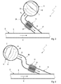
- FIGS. 1 to 4 includes an exhaust system 1 only partially shown here, which is used in an internal combustion engine, which is preferably arranged in a motor vehicle, for discharging exhaust gas, at least one exhaust line 2, which has at least one exhaust-carrying exhaust pipe 3.
- An exhaust gas flow in the exhaust pipe 3 is in the Figures 1 and 2 indicated by an arrow and denoted by 4.
- the exhaust system 1 comprises at least one active silencer 5. This comprises a silencer housing 6 and at least one electro-acoustic transducer 7, which is arranged in the silencer housing 6.
- a connecting tube 8 is provided, via which the silencer 5 is acoustically connected to the exhaust pipe 3.
- the connecting pipe 8 fluidly connects the muffler housing 6 with the exhaust pipe 3.
- the connecting pipe 8 defines for this purpose an indicated by arrows sound propagation path 9, which is formed in the connecting pipe 8 and allows the propagation of airborne sound.
- Pressure pulsations 10 are indicated, which represent a propagation of airborne sound along the sound propagation path 9 from the transducer 7 in the direction of the exhaust pipe 3. These pressure pulses 10 are phase-shifted to pressure pulsations of a sound to be damped, which is carried in the exhaust stream 4.
- the connecting pipe 8 comprises a radiator section 11 which is arranged in the connecting pipe 8 between the silencer housing 6 and the exhaust pipe 3.
- a cooler section 11 can be dispensable in principle.
- the radiator section 11 includes a radiator wall 12 that completely encloses a cross section 13 of the connection pipe 8 and a cross section 13 of the radiator section 11 in the circumferential direction.
- the radiator portion 11 has a straight-line structure and accordingly has a rectilinear longitudinal central axis 14, which in the in the Fig. 1 and 2 shown, preferred embodiment, in which the connecting tube 8 is configured in a straight line, coincides with a longitudinal central axis 15 of the connecting tube 8.
- the sound propagation path 9 may according to a preferred embodiment for a in the Figures 2 and 5 indicated by arrows heat radiation 16, which emanates from the exhaust gas or from the exhaust stream 4 in the exhaust pipe 3, be configured impermeable. As a result, the thermal load of the transducer 7 by heat radiation 16 can be significantly reduced.
- the sound propagation path 9 for the heat radiation 16 can be made opaque that the connecting pipe 8 is curved, such that through the connecting pipe 8 through no straight connection leads unhindered from the exhaust pipe 3 to the muffler housing 6.
- a connecting tube 8 which has a 90 ° bend 25 between the exhaust pipe 3 and the silencer housing 6, which prevents a straight-line propagation of the heat radiation from the exhaust pipe 3 to the silencer housing 6.
- Fig. 4 shows a variant in which the connecting tube 8 has an S-shaped arc 26 or S-bow 26 and S-shock 26, which is also a rectilinear propagation of heat radiation from the exhaust pipe 3 to the muffler housing 6 prevents.
- a plurality of internal cooling fins 17 are provided in the cross section 13 of the connecting tube 8 and the radiator section 11, which are arranged in the connecting tube 8 and here in the radiator section 11 that the arrangement of the internal cooling fins 17 is permeable to the airborne sound.
- the inner cooling fins 17 according to the above idea, the heat radiation even with a straight connecting pipe 8, be arranged so that they cross-section 13 of the radiator portion 11 in a viewing direction 18 which is parallel to the longitudinal central axis 14 of the radiator portion 11, opaque close.
- the internal cooling fins 17 are expediently made of a metallic material.
- it can be sheet metal body.
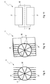
- the inner cooling rib 17 project from the cooler wall 12 inwards and thus protrude into the cross section 13.
- the inner cooling fins 17 each configured as blades, which are employed with respect to the longitudinal central axis 14.
- the inner cooling fins 17 according to the embodiments of FIGS. 6 to 11 be arranged in a star shape, wherein the individual inner cooling ribs 17 can be supported radially inwardly in a common center to each other. It is also possible to arrange the inner cooling ribs 17 so that they are free-standing radially inward, so do not touch each other.
- the inner cooling fins 17 are arranged so as to have the structure of a swirl generator.
- the internal cooling ribs 17 may be arranged in the manner of a static mixer.
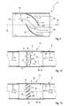
- the Figures 2 . 12 and 13 show embodiments in which the inner cooling fins 17 are designed as a straight blades, which are parallel to each other.
- the internal cooling fins 17 of the Figures 2 and 12 are employed with respect to the longitudinal central axis 14 at 90 ° so that they extend with their surface perpendicular to the longitudinal central axis 14.
- the inner cooling ribs 17 in the axial direction that is arranged offset from each other parallel to the longitudinal center axis 14 to each other.
- the axially offset inner cooling fins 17 are also offset from one another transversely to the longitudinal central axis 14, such that the optionally desired opaque obstruction of the cross section 13 results in the viewing direction 18.
- the paddle-shaped inner cooling fins 17, which extend parallel to each other, are employed at about 45 ° relative to the longitudinal central axis 14. Furthermore, the internal cooling ribs 17 are here dimensioned such that in the viewing direction 18, an overlap for the opaque obstruction of the cross section 13 sets.
- FIGS. 5 to 11 and 13 is a first edge 19 of an inner fin 17 in the viewing direction 18 overlapping or aligned to a second edge 20 of an adjacent inner fin 17.
- the first edge 19 is facing the muffler housing 6, while the second edge 20 faces away from the muffler housing 6.
- the radiator section 11 expediently has a plurality of outer cooling ribs 21 which protrude outward from the radiator wall 12.
- the outer cooling fins 21 are expedient parallel to Longitudinal axis 14 of the radiator portion 11 aligned.
- Fig. 2 an embodiment in which the outer cooling ribs 21 are configured annular and extend in the circumferential direction and perpendicular to the longitudinal center axis 14 of the radiator portion 11.
- the outer cooling fins 21 extend in a star shape.
- the outer cooling fins 21 extend parallel to each other.
- a cooling air flow generator 22 is shown, which is indicated here by a blower.
- a cooling air flow 23 can be generated, which is indicated here by arrows and which acts on the radiator section 11 from the outside.
- heat can be dissipated in the environment.
- the cooler section 11 is expediently a tubular body which is separate with regard to the connecting pipe 8 and which is installed in a suitable manner in the connecting pipe 8, compare in particular the illustrations of FIGS FIGS. 12 and 13 ,
- the inner cooling fins 17 and / or the outer cooling fins 21 may be integrally formed on the radiator wall 12.
- the radiator section 11 is thus a monolithic casting which integrally comprises the radiator wall 12 and the internal cooling fins 17 and optionally the external cooling fins 21.
- the heat radiation 16 impermeable embodiment of the sound propagation path 9 or by the opaque arrangement of the inner cooling fins 17 is according to the Figures 2 and 5 the coming of the exhaust pipe 3 heat radiation 16 at the inner cooling fins 17 partially reflected and partially absorbed.
- the reflected heat does not contribute to the heating of the inside Cooling ribs 17 at.
- the absorbed heat heats up the internal cooling ribs 17. Due to their thermal conductivity, the internal cooling ribs 17 can transmit the absorbed heat to the radiator wall 12. From the cooler wall 12, the heat absorbed in the examples passes into the outer cooling fins 21 and can be radiated by them into the environment. Possibly. This heat output can be supported by the cooling air flow 23.
- the internal cooling ribs 17 are connected to a cooling circuit, in which a liquid coolant circulates, so that the internal cooling ribs 17 are flowed through by this coolant.
Landscapes
- Engineering & Computer Science (AREA)
- Chemical & Material Sciences (AREA)
- Combustion & Propulsion (AREA)
- Mechanical Engineering (AREA)
- General Engineering & Computer Science (AREA)
- Health & Medical Sciences (AREA)
- Chemical Kinetics & Catalysis (AREA)
- Toxicology (AREA)
- Exhaust Silencers (AREA)
Abstract
Description
- Die vorliegende Erfindung betrifft eine Abgasanlage für eine Brennkraftmaschine, insbesondere eines Kraftfahrzeugs.
- Eine Abgasanlage umfasst üblicherweise zumindest einen Abgasstrang, der zumindest ein Abgas führendes Abgasrohr aufweist. Der jeweilige Abgasstrang dient zum Abführen von Abgas, das in Brennräumen der Brennkraftmaschine entsteht. Je nach Größe der Brennkraftmaschine kommt die Abgasanlage mit einem einzigen Abgasstrang aus oder umfasst zumindest zwei Abgasstränge, bspw. bei einem V-Motor. Im jeweiligen Abgasstrang sind üblicherweise Abgasnachbehandlungseinrichtungen angeordnet, wie z. B. Katalysatoren, Partikelfilter, SCR-Anlagen und Schalldämpfer, die über Abgasrohre miteinander verbunden sind. Eingangsseitig umfasst ein Abgasstrang üblicherweise einen Abgassammler, sog. "Abgaskrümmer", während endseitig ein Endrohr angeordnet ist, sog. "Auspuff". Auch diese endseitigen Komponenten können mit Abgasrohren in Verbindung stehen.
- Bei Schalldämpfern wird zwischen passiven Schalldämpfern und aktiven Schalldämpfern unterschieden. Die passiven Schalldämpfer dämpfen den im Abgas transportieren Luftschall mittels Resonanz-, Reflexions-, Expansions- und/oder Absorptionseffekten. Im Unterschied dazu arbeitet ein aktiver Schalldämpfer mit Gegenschall oder Antischall, der mit Hilfe eines entsprechenden elektro-akustischen Wandlers erzeugt wird, bei dem es sich in der Regel um einen Lautsprecher handelt. Ebenso sind Kombinationen aus aktiven und passiven Schalldämpfern möglich. Im vorliegenden Zusammenhang soll daher insbesondere ausgeschlossen werden, dass ein aktiver Schalldämpfer ausschließlich mit Antischall arbeitet. Vielmehr soll ein aktiver Schalldämpfer im Rahmen der vorliegenden Erfindung optional auch Eigenschaften und/oder Komponenten eines passiven Schalldämpfers umfassen können, wie z.B. wenigstens eine Resonanz-, Reflexions-, Expansions- und/oder Adsorptionskammer.
- Ein aktiver Schalldämpfer kann ein Schalldämpfergehäuse und zumindest einen im Schalldämpfergehäuse angeordneten elektro-akustischen Wandler sowie zumindest ein Verbindungsrohr aufweisen. Mit Hilfe des Verbindungsrohrs kann das Schalldämpfergehäuse fluidisch mit dem Abgasrohr verbunden werden. Auf diese Weise ist das Schalldämpfergehäuse im Nebenschluss an den Abgasstrang angeschlossen, sodass es vom Abgas nicht durchströmt wird. Die fluidische Verbindung zwischen Schalldämpfergehäuse und Abgasrohr, die mit Hilfe des Verbindungsrohrs geschaffen wird, stellt dagegen eine akustische Kopplung für Luftschall sicher, sodass sich zum einen der im Abgas mitgeführte Schall in Richtung Schalldämpfergehäuse ausbreiten kann, während zum anderen der vom elektro-akustischen Wandler generierte Schall in das Abgasrohr abgestrahlt werden kann. Über das Verbindungsrohr wird außerdem eine körperliche Beabstandung zwischen Schalldämpfergehäuse und Abgasrohr realisiert, wodurch die thermische Belastung des Wandlers reduziert werden kann. Es hat sich jedoch gezeigt, dass die im Abgasrohr geführten heißen Abgase dennoch zu einer hohen thermischen Belastung des Wandlers führen können. Zum einen kann das heiße Abgas durch Diffusionsvorgänge in das Verbindungsrohr eintreten und bis zum Wandler gelangen. Zum anderen heizt das Abgas das Abgasrohr auf, sodass Wärme über Wärmeleitung von Abgasrohr über das Verbindungsrohr zum Schalldämpfergehäuse gelangen kann. Schließlich kann sich auch Wärmestrahlung vom Abgas bzw. vom Abgasrohr durch das Verbindungsrohr bis zum Wandler ausbreiten.
- Um die thermische Belastung des Wandlers sowie einer ggf. ebenfalls im Schalldämpfergehäuse angeordneten Elektronik des aktiven Schalldämpfers zu reduzieren, ist es grundsätzlich möglich, das Verbindungsrohr zwischen dem Schalldämpfergehäuse und dem Abgasrohr mit einem Kühlerabschnitt auszustatten. Auf diese Weise kann das Verbindungsrohr gekühlt werden, indem über dem Kühlerabschnitt Wärme nach außen abgegeben wird. Bspw. kann das Verbindungsrohr im Kühlerabschnitt nach außen abstehende außenliegende Kühlrippen aufweisen. Ebenso ist denkbar, im Kühlerabschnitt einen Kühlmantel auszubilden, der von einem Kühlmittel durchströmt wird. Bspw. kann dieser Kühlmantel an einem Kühlkreis der mit der Abgasanlage ausgestatteten Brennkraftmaschine fluidisch gekoppelt sein.
- Die vorliegende Erfindung beschäftigt sich mit dem Problem, für eine Abgasanlage der eingangs genannten Art eine verbesserte oder zumindest eine andere Ausführungsform anzugeben, die sich insbesondere durch eine reduzierte thermische Belastung des Wandlers auszeichnet.
- Dieses Problem wird erfindungsgemäß durch den Gegenstand des unabhängigen Anspruchs gelöst. Vorteilhafte Ausführungsformen sind Gegenstand der abhängigen Ansprüche.
- Die Erfindung beruht auf dem allgemeinen Gedanken, mit Hilfe wenigstens einer innenliegenden Kühlrippe, die in den Querschnitt des Verbindungsrohrs hineinragt, die thermische Masse des Verbindungsrohrs zu vergrößern, wodurch die Wärme zeitlich verzögert bzw. gedämpft vom Abgasrohr zum Schalldämpfergehäuse gelangt. Auf diese Weise kann die thermische Belastung des Wandlers reduziert werden.
- Durch die reduzierte thermische Belastung des Wandlers sowie ggf. anderer elektronischer Komponenten im Schalldämpfergehäuse ist es außerdem möglich, den aktiven Schalldämpfer weiter stromauf, näher an der Brennkraftmaschine anzuordnen, als dies bislang möglich ist. Eine motornahe Anordnung kann für bestimmte Anforderungen von Vorteil sein.
- Gemäß einer vorteilhaften Ausführungsform kann vorgesehen sein, die wenigstens eine innenliegende Kühlrippe in einem Kühlerabschnitt des Verbindungsrohrs anzuordnen, sodass die jeweilige innenliegende Kühlrippe im Kühlerabschnitt von einer Kühlerwand des Kühlerabschnitts nach innen vorsteht und in den Querschnitt des Verbindungsrohrs bzw. des Kühlerabschnitts hineinragt. Durch die Positionierung der jeweiligen innenliegenden Kühlrippe im Kühlerabschnitt kann die auf die jeweilige innenliegende Kühlrippe übertragene Wärme von der jeweiligen innenliegenden Kühlrippe auf eine den Querschnitt des Verbindungsrohrs in Umfangsrichtung umfassende Kühlerwand des Kühlerabschnitts abgeleitet und durch eine ggf. vorgesehene Kühlung des Kühlerabschnitts abgeführt werden. Insoweit lässt sich durch die Positionierung der jeweiligen innenliegenden Kühlrippe im Kühlerabschnitt eine Kühlung der jeweiligen innenliegenden Kühlrippe realisieren, was die Effizienz des thermischen Schutzes des Wandlers verbessert. Auch hier ist von besonderer Bedeutung, dass die jeweilige innenliegende Kühlrippe zur Erhöhung der thermischen Masse des Kühlerabschnitts beiträgt.
- Gemäß einer anderen vorteilhaften Ausführungsform kann der zuvor genannte Kühlerabschnitt ein bzgl. des Verbindungsrohrs separater Rohrkörper sein, der auf geeignete Weise in das Verbindungsrohr eingebaut ist, bspw. über Schweißverbindungen oder über Flanschverbindungen. Hierdurch ist es insbesondere möglich, den Kühlerabschnitt aus einem anderen Material herzustellen als das Verbindungsrohr. Bspw. kann das Verbindungsrohr aus einer Eisenlegierung bzw. aus einer Stahllegierung hergestellt sein, während der Rohrkörper des Kühlerabschnitts aus einer Leichtmetalllegierung hergestellt ist, die sich durch eine deutlich bessere Wärmeleitfähigkeit auszeichnet. Darüber hinaus ermöglicht der separate Rohrkörper des Kühlerabschnitts eine Ausführungsform, bei welcher das Verbindungsrohr beiderseits des Kühlerabschnitts aus unterschiedlichen Materialien hergestellt ist. So kann das Verbindungsrohr bspw. vom Kühlerabschnitt bis zum Abgasrohr aus einem metallischen Werkstoff hergestellt sein, während es vom Kühlerabschnitt zum Schalldämpfergehäuse aus einem Kunststoff hergestellt sein kann.
- Entsprechend einer anderen vorteilhaften Ausführungsform kann vorgesehen sein, den mit Hilfe des Verbindungsrohrs für Luftschall geschaffenen akustischen Kopplungspfad so auszugestalten, dass er für Wärmestrahlung undurchdringbar ist. Auf diese Weise wird verhindert, dass Wärmestrahlung vom Abgasstrom im Abgasrohr bzw. vom Abgasrohr auf direktem Weg durch das Verbindungsrohr hindurch zum Wandler gelangt. Auf diese Weise kann die thermische Belastung des Wandlers durch Wärmestrahlung signifikant reduziert werden.
- Gemäß einer ersten allgemeinen Weiterbildung dieser Ausführungsform wird hierzu vorgeschlagen, das Verbindungsrohr gekrümmt auszuführen, derart, dass durch das Verbindungsrohr hindurch kein geradliniger, vom Abgasrohr zum Schalldämpfergehäuse durchgehender Strahlungsweg vorhanden ist. Somit kann eine direkte Aufheizung des Wandlers durch Wärmestrahlung vermieden werden. Hierzu kann das Verbindungsrohr z.B. einen 90°-Bogen oder einen S-Bogen aufweisen.
- Entsprechend einer zweiten allgemeinen Weiterbildung wird vorgeschlagen, die wenigstens eine innenliegende Kühlrippe in einem Querschnitt des Verbindungsrohrs derart anzuordnen, dass das Verbindungsrohr für Luftschall durchlässig bleibt, während die wenigstens eine innenliegende Kühlrippe den Querschnitt des Verbindungsrohrs in einer parallel zur Längsmittelachse des Verbindungsrohrs verlaufenden Blickrichtung blickdicht verschließt. Mit Hilfe der jeweiligen innenliegenden Kühlrippe kann somit ebenfalls effektiv ein Durchtritt von Wärmestrahlung durch das Verbindungsrohr hindurch verhindert werden, während die Ausbreitung des Luftschalls durch das Verbindungsrohr weitgehend ungehindert ist. Auch hierdurch lässt sich die thermische Belastung des Wandlers signifikant reduzieren. Die Verwendung der wenigstens einen innenliegenden Kühlrippe zum blickdichten Versperren des für Luftschall durchlässigen Querschnitts des Verbindungsrohrs ermöglicht es dabei, ein geradliniges Verbindungsrohr zu verwenden, das besonders preiswert realisierbar ist und dementsprechend bevorzugt ist. Grundsätzlich lassen sich die hier vorgeschlagenen, alternativen Weiterbildungen auch miteinander kombinieren, sodass einerseits ein gekrümmtes Verbindungsrohr vorgesehen ist, dessen Querschnitt andererseits mit der wenigstens einen innenliegenden Kühlrippe in der Blickrichtung blickdicht verschlossen ist.
- Die jeweilige innenliegende Kühlrippe kann zweckmäßig ein Blechkörper sein, der sich durch eine hohe Wärmeleitfähigkeit und Hitzebeständigkeit auszeichnet. Zweckmäßig sind mehrere derartige innenliegende Kühlrippen vorgesehen, die von einer Rohrwand des Verbindungsrohrs oder von der zuvor genannten Kühlerwand des Kühlerabschnitts nach innen vorstehen. Die Verwendung von mehreren innenliegende Kühlrippen ermöglicht eine Ausgestaltung der innenliegenden Kühlrippe derart, dass sie die Luftschallausbreitung entlang des Schallausbreitungspfads nur unwesentlich behindern. Alternativ zu mehreren innenliegende Kühlrippen, die jeweils für sich von der Rohrwand bzw. von der Kühlwand nach innen abstehen, kann die innenliegende Kühlrippe auch durch ein Lochblech gebildet sein. Ein derartiges Lochblech kann insbesondere so angeordnet werden, dass es den Querschnitt des Verbindungsrohrs bzw. des Kühlerabschnitts für Wärmestrahlung verschließt. Beispielsweise können die Löcher des Lochblechs durch das Ausstellen von Laschen gebildet sein, wobei besagte Laschen zweckmäßig derart ausgestellt sind, dass sie die zugehörigen Öffnungen in der Blickrichtung versperren.
- Entsprechend einer bevorzugten Ausführungsform kann die jeweilige innenliegende Kühlrippe dagegen als Schaufeln ausgestaltet sein, die insbesondere gegenüber der Längsmittelachse angestellt ist. Derartige Schaufeln, die in einem durchströmten Rohr - was hier beim Verbindungsrohr nicht der Fall ist - auch als Leitschaufeln bezeichnet werden können, zeichnen sich durch einen vergleichsweise geringen akustischen Widerstand aus, sodass derartige Schaufeln den Schallausbreitungspfad nur geringfügig behindern.
- Gemäß einer vorteilhaften Weiterbildung können mehrere innenliegende Kühlrippen sternförmig angeordnet sein, wodurch sich eine Rotationssymmetrie für die Wechselwirkung der innenliegende Kühlrippen mit dem Schallausbreitungspfad ergibt. Die sternförmig angeordneten innenliegenden Kühlrippen können radial innen freistehend angeordnet sein, sodass sie sich gegenseitig nicht berühren. Alternativ ist es ebenso möglich, dass sich die sternförmig angeordneten innenliegenden Kühlrippen in einem gemeinsamen Zentrum aneinander abstützen. Die freistehende Anordnung vermeidet thermisch bedingte Spannungen. Ein gemeinsames Zentrum ermöglicht dagegen die Realisierung der innenliegenden Kühlrippen als Einheit, die in den jeweiligen Querschnitt als separates Bauteil eingesetzt werden kann. Sofern die sternförmig angeordneten innenliegenden Kühlrippen als Schaufeln ausgestaltet sind, kann die Anordnung der innenliegenden Kühlrippen wie ein statischer Mischer und insbesondere in Form eines Drallerzeugers ausgestaltet sein. Da das Verbindungsrohr vom Abgas nicht durchströmt ist, erfolgt im Bereich der innenliegenden Kühlrippen keine Durchmischung bzw. Drallerzeugung, jedoch insbesondere ein blickdichtes Verschließen des jeweiligen Querschnitts bei offenem und weitgehend ungehindertem Schallausbreitungspfad.
- Entsprechend einer anderen vorteilhaften Ausführungsform kann sich die jeweilige innenliegende Kühlrippe zumindest entlang der Kühlerwand in der Längsrichtung des Verbindungsrohrs bzw. des Kühlerabschnitts und in der Umfangsrichtung erstrecken. Somit folgt der Schallausbreitungspfad einer gekrümmten Bahn, die für die Schallausbreitung ein vernachlässigbares Hindernis darstellt und die für die geradlinige Wärmestrahlung dagegen ein unüberwindbares Hindernis darstellt.
- Bei einer anderen Ausführungsform können mehrere innenliegende Kühlrippen als geradlinige Schaufeln ausgestaltet sein, die parallel zueinander verlaufen. Insbesondere können die innenliegenden Kühlrippen dadurch als Schaufelgitter konzipiert sein.
- Gemäß einer anderen zweckmäßigen Ausführungsform, die mit mehreren innenliegenden Kühlrippen arbeitet, kann eine Anströmkante einer innenliegende Kühlrippe eine Abströmkante einer benachbarten innenliegenden Kühlrippe in der Blickrichtung überlappen oder damit in der Blickrichtung fluchten. Auf diese Weise wird besonders einfach erreicht, dass die einzelnen innenliegenden Kühlrippen jeweils für sich einen Abschnitt des Querschnitts des Verbindungsrohrs bzw. des Kühlerabschnitts in der Blickrichtung versperren, derart, dass alle innenliegende Kühlrippe zusammen insbesondere den gesamten Querschnitt in der Blickrichtung blickdicht verschließen, während gleichzeitig zwischen benachbarten innenliegenden Kühlrippen ausreichend Lücken bzw. Abstände vorhanden sind, die einen weitgehend ungehinderten Durchtritt für Luftschall ermöglichen.
- Anstelle einer blickdichten Anordnung mehrerer innenliegender Kühlrippen kann bei einer anderen Ausführungsform vorgesehen sein, dass sich die mehreren innenliegenden Kühlrippen geradlinig und parallel zur Längsmittelachse des Verbindungsrohrs bzw. parallel zur Längsmittelachse des Kühlerabschnitts erstrecken. Die Anordnung der innenliegenden Kühlrippen ist dann für Wärmestrahlung grundsätzlich durchlässig, bewirkt dennoch eine vergleichsweise hohe Wärmeaufnahme, was die wärmeempfindlichen Komponenten des aktiven Schalldämpfers schützt. Gleichzeitig wird bei dieser Ausführungsform der Durchtritt des Luftschalls durch die Anordnung der innenliegenden Kühlrippen begünstigt, was die Wirksamkeit des aktiven Schalldämpfers verbessert.
- Gemäß einer anderen vorteilhaften Ausführungsform kann der zuvor genannte Kühlerabschnitt mehrere außenliegende Kühlrippen aufweisen, die von der Kühlerwand des Kühlerabschnitts nach außen abstehen. Durch diese Maßnahme wird die für die Wärmeabstrahlung zur Verfügung stehende Oberfläche des Kühlerabschnitts signifikant vergrößert, was die Abgabe von Wärme in die Umgebung des Verbindungsrohrs verbessert.
- Gemäß einer zweckmäßigen Weiterbildung können die außenliegenden Kühlrippen parallel zur Längsmittelachse des Kühlerabschnitts ausgerichtet sein und sternförmig oder zueinander parallel angeordnet sein. Die sternförmige Anordnung verbessert die Wärmeabstrahlung. Die parallele Anordnung vereinfacht dagegen die Herstellbarkeit des Kühlerabschnitts mit den außenliegenden Kühlrippen als integrale Einheit, insbesondere als Gussteil.
- Gemäß einer anderen vorteilhaften Ausführungsform kann ein Kühlluftstromerzeuger vorgesehen sein, der einen den Kühlerabschnitt von außen beaufschlagenden Kühlluftstrom erzeugt. Auf diese Weise wird der Kühlerabschnitt aktiv gekühlt, nämlich durch den speziell dafür erzeugten Kühlluftstrom. Alternativ ist es grundsätzlich möglich, den Kühlerabschnitt mit einem Kühlmantel auszustatten, der an einen Kühlkreis angeschlossen ist, in dem ein Kühlmittel, vorzugsweise eine Kühlflüssigkeit, zirkuliert. Bspw. kann ein derartiger Kühlkreis mit einem Kühlkreis der Brennkraftmaschine gekoppelt sein.
- Entsprechend einer anderen vorteilhaften Ausführungsform kann die jeweilige innenliegende Kühlrippe als Hohlkörper ausgestaltet sein und von einem Kühlmittel, vorzugsweise von einer Kühlflüssigkeit, durchströmbar sein. Die jeweilige innenliegende Kühlrippe ist dabei durch die Kühlerwand des Kühlerabschnitts hindurch an einen Kühlkreis angeschlossen, in dem das Kühlmittel zirkuliert. Insbesondere kann dieser Kühlkreis mit einem Kühlkreis der Brennkraftmaschine gekoppelt sein. Außerdem ist es grundsätzlich möglich, die aktiv mit einem Kühlmittel gekühlten innenliegenden Kühlrippen mit dem vorstehend genannten Kühlmantel zum Kühlen des Kühlerabschnitts zu kombinieren.
- Gemäß einer anderen vorteilhaften Ausführungsform kann die jeweilige innenliegende Kühlrippe integral an der Rohrwand des Verbindungsrohrs oder an der Kühlwand des Kühlerabschnitts ausgeformt sein. Die integrale Bauweise erleichtert dabei die Herstellung des aktiven Schalldämpfers bzw. der Abgasanlage. Insbesondere wird durch die integrale Bauweise die Realisierung des vorstehend genannten Rohrkörpers als monolithisches Gussteil vereinfacht. Zusätzlich oder alternativ können die vorstehend genannten außenliegenden Kühlrippen des Kühlerabschnitts integral an besagter Kühlwand ausgeformt sein, was auch hier eine preiswerte Herstellung als Gussteil vereinfacht. Insbesondere kann somit der Kühlerabschnitt in Form eines monolithischen Rohrkörpers realisiert werden, der integral die wenigstens eine innenliegende Kühlrippe und optional außerdem die außenliegenden Kühlrippen umfassen kann.
- Weitere wichtige Merkmale und Vorteile der Erfindung ergeben sich aus den Unteransprüchen, aus den Zeichnungen und aus der zugehörigen Figurenbeschreibung anhand der Zeichnungen.
- Es versteht sich, dass die vorstehend genannten und die nachstehend noch zu erläuternden Merkmale nicht nur in der jeweils angegebenen Kombination, sondern auch in anderen Kombinationen oder in Alleinstellung verwendbar sind, ohne den Rahmen der vorliegenden Erfindung zu verlassen.
- Bevorzugte Ausführungsbeispiele der Erfindung sind in den Zeichnungen dargestellt und werden in der nachfolgenden Beschreibung näher erläutert, wobei sich gleiche Bezugszeichen auf gleiche oder ähnliche oder funktional gleiche Bauteile beziehen.
- Es zeigen, jeweils schematisch,
- Fig. 1
- eine stark vereinfachte Prinzipdarstellung einer Abgasanlage im Bereich eines aktiven Schalldämpfers,
- Fig. 2
- eine Ansicht wie in
Fig. 1 bei längsgeschnittenem Kühlerabschnitt, - Fig. 3
- eine Ansicht wie in
Fig. 1 , jedoch bei einer anderen Ausführungsform, - Fig. 4
- eine Ansicht wie in
Fig. 3 , jedoch bei einer weiteren Ausführungsform, - Fig. 5
- einen stark vereinfachten Längsschnitt durch den Kühlerabschnitt,
- Fig. 6
- einen Kühlerabschnitt im Querschnitt,
- Fig. 7
- eine isometrische Ansicht des Kühlerabschnitts aus
Fig. 6 , - Fig. 8
- eine Seitenansicht des Kühlerabschnitts aus
Fig. 6 , - Fig. 9
- ein Querschnitt des Kühlerabschnitts wie in
Fig. 6 , jedoch bei einer anderen Ausführungsform, - Fig. 10
- eine isometrische Ansicht des Kühlerabschnitts aus
Fig. 9 , - Fig. 11
- eine Seitenansicht des Kühlerabschnitts aus
Fig. 9 , - Fig. 12
- ein stark vereinfachter Längsschnitt der Abgasanlage im Bereich eines Kühlerabschnitts bei einer anderen Ausführungsform,
- Fig. 13
- ein Längsschnitt wie in
Fig. 12 , jedoch bei einer weiteren Ausführungsform, - Fig. 14
- einen anderen Kühlerabschnitt im Querschnitt,
- Fig. 15
- einen weiteren Kühlerabschnitt im Querschnitt,
- Fig. 16
- einen nochmals anderen Kühlerabschnitt im Querschnitt.
- Entsprechend den
Figuren 1 bis 4 umfasst eine hier nur teilweise dargestellte Abgasanlage 1, die bei einer Brennkraftmaschine, die vorzugsweise in einem Kraftfahrzeug angeordnet ist, zum Abführen von Abgas dient, zumindest einen Abgasstrang 2, der zumindest ein abgasführendes Abgasrohr 3 aufweist. Eine Abgasströmung im Abgasrohr 3 ist in denFiguren 1 und 2 durch einen Pfeil angedeutet und mit 4 bezeichnet. Die Abgasanlage 1 umfasst zumindest einen aktiven Schalldämpfer 5. Dieser weist ein Schalldämpfergehäuse 6 und zumindest einen elektro-akustischen Wandler 7 auf, der im Schalldämpfergehäuse 6 angeordnet ist. Ferner ist ein Verbindungsrohr 8 vorgesehen, über das der Schalldämpfer 5 akustisch an das Abgasrohr 3 angeschlossen ist. Zu diesem Zweck verbindet das Verbindungsrohr 8 das Schalldämpfergehäuse 6 fluidisch mit dem Abgasrohr 3. Das Verbindungsrohr 8 definiert hierzu einen durch Pfeile angedeuteten Schallausbreitungspfad 9, der im Verbindungsrohr 8 ausgebildet ist und der eine Ausbreitung von Luftschall ermöglicht. In denFiguren 1 bis 4 sind Druckpulsationen 10 angedeutet, die eine Ausbreitung von Luftschall entlang des Schallausbreitungspfads 9 vom Wandler 7 in Richtung Abgasrohr 3 repräsentieren. Diese Druckpulse 10 sind phasenverschoben zu Druckpulsationen eines zu bedämpfenden Schalls, der im Abgasstrom 4 mitgeführt wird. - Im gezeigten, bevorzugten Beispiel der Abgasanlage 1 umfasst das Verbindungsrohr 8 einen Kühlerabschnitt 11, der im Verbindungsrohr 8 zwischen dem Schalldämpfergehäuse 6 und dem Abgasrohr 3 angeordnet ist. Bei einer anderen Ausführungsform kann ein derartiger Kühlerabschnitt 11 grundsätzlich entbehrlich sein.
- Entsprechend den
Figuren 1 bis 16 umfasst der Kühlerabschnitt 11 eine Kühlerwand 12, die einen Querschnitt 13 des Verbindungsrohrs 8 bzw. einen Querschnitt 13 des Kühlerabschnitts 11 in der Umfangsrichtung vollständig umschließt. Ferner besitzt der Kühlerabschnitt 11 einen geradlinigen Aufbau und weist dementsprechend eine geradlinige Längsmittelachse 14 auf, die in der in denFig. 1 und 2 gezeigten, bevorzugten Ausführungsform, bei welcher das Verbindungsrohr 8 geradlinig ausgestaltet ist, mit einer Längsmittelachse 15 des Verbindungsrohrs 8 zusammenfällt. - Der Schallausbreitungspfad 9 kann entsprechend einer bevorzugten Ausführungsform für eine in den
Figuren 2 und5 durch Pfeile angedeutete Wärmestrahlung 16, die vom Abgas bzw. vom Abgasstrom 4 im Abgasrohr 3 ausgeht, undurchlässig ausgestaltet sein. Hierdurch kann die thermische Belastung des Wandlers 7 durch Wärmestrahlung 16 erheblich reduziert werden. - In einem besonders einfachen Fall, der hier in den
Fig. 3 und 4 gezeigt ist, kann der Schallausbreitungspfad 9 für die Wärmestrahlung 16 dadurch undurchlässig konzipiert werden, dass das Verbindungsrohr 8 gekrümmt ausgeführt wird, derart, dass durch das Verbindungsrohr 8 hindurch keine geradlinige Verbindung unbehindert vom Abgasrohr 3 zum Schalldämpfergehäuse 6 führt. Beispielsweise zeigtFig. 3 hierzu ein Verbindungsrohr 8, das zwischen dem Abgasrohr 3 und dem Schalldämpfergehäuse 6 einen 90°-Bogen 25 aufweist, der eine geradlinige Ausbreitung der Wärmestrahlung vom Abgasrohr 3 zum Schalldämpfergehäuse 6 verhindert.Fig. 4 zeigt eine Variante, bei welcher das Verbindungsrohr 8 einen S-förmigen Bogen 26 oder S-Bogen 26 bzw. S-Schlag 26 aufweist, der ebenso eine geradlinige Ausbreitung von Wärmestrahlung vom Abgasrohr 3 zum Schalldämpfergehäuse 6 verhindert. - Im Unterschied dazu wird bei den in den
Fig. 1 und 2 gezeigten Ausführungsformen ein geradliniges Verbindungsrohr 8 verwendet. Die nachfolgend beschriebenen Merkmale sind jedoch grundsätzlich auch bei einem gekrümmten Verbindungsrohr 8 realisierbar. - Um die Wärmeübertragung vom Abgasrohr 3 zum Schalldämpfergehäuse 6 entlang des Schallausbreitungspfads 9 zu reduzieren, sind im Querschnitt 13 des Verbindungsrohrs 8 bzw. des Kühlerabschnitts 11 hier mehrere innenliegende Kühlrippen 17 vorgesehen, die im Verbindungsrohr 8 bzw. hier im Kühlerabschnitt 11 so angeordnet sind, dass die Anordnung der innenliegende Kühlrippen 17 für den Luftschall durchlässig ist. Optional können die innenliegenden Kühlrippen 17 gemäß der vorstehenden Idee, die Wärmestrahlung auch bei einem geradlinigem Verbindungsrohr 8 zu reduzieren, so angeordnet sein, dass sie den Querschnitt 13 des Kühlerabschnitts 11 in einer Blickrichtung 18, die parallel zur Längsmittelachse 14 des Kühlerabschnitts 11 verläuft, blickdicht verschließen. Obwohl bei den hier gezeigten Ausführungsbeispielen stets mehrere innenliegende Kühlrippen 17 vorgesehen sind, ist grundsätzlich auch eine Ausführungsform denkbar, bei der nur eine einzige innenliegende Kühlrippe 17 vorhanden ist. Dabei kann grundsätzlich auch mit nur einer einzigen innenliegenden Kühlrippe 17 der Querschnitt 13 blickdicht versperrt werden.
- Die innenliegenden Kühlrippen 17 sind zweckmäßig aus einem metallischen Werkstoff hergestellt. Bspw. kann es sich um Blechkörper handeln. Die innenliegenden Kühlrippe 17 stehen von der Kühlerwand 12 nach innen ab und ragen somit in den Querschnitt 13 hinein. Bei den Ausführungsformen der
Fig. 2 und6 bis 13 sind die innenliegenden Kühlrippen 17 jeweils als Schaufeln ausgestaltet, die gegenüber der Längsmittelachse 14 angestellt sind. Zweckmäßig können die innenliegenden Kühlrippen 17 gemäß den Ausführungsformen derFiguren 6 bis 11 sternförmig angeordnet sein, wobei sich die einzelnen innenliegenden Kühlrippen 17 radial innen in einem gemeinsamen Zentrum aneinander abstützen können. Ebenso ist es möglich, die innenliegenden Kühlrippen 17 so anzuordnen, dass sie radial innen freistehend sind, sich gegenseitig also nicht berühren. Bei den Ausführungsformen derFiguren 6 bis 11 sind die innenliegenden Kühlrippen 17 so angeordnet, dass sie die Struktur eines Drallerzeugers besitzen. Generell können die innenliegenden Kühlrippen 17 nach Art eines statischen Mischers angeordnet sein. - Die
Figuren 2 ,12 und 13 zeigen Ausführungsformen, bei denen die innenliegenden Kühlrippen 17 als geradlinige Schaufeln ausgestaltet sind, die zueinander parallel verlaufen. Die innenliegende Kühlrippen 17 derFiguren 2 und12 sind dabei gegenüber der Längsmittelachse 14 mit 90° angestellt, sodass sie sich mit ihrer Fläche senkrecht zur Längsmittelachse 14 erstrecken. Des Weiteren sind bei den Ausführungsformen derFiguren 2 und12 die innenliegenden Kühlrippen 17 in der Axialrichtung, also parallel zur Längsmittelachse 14 zueinander versetzt angeordnet. Des Weiteren sind die axial zueinander versetzten innenliegenden Kühlrippen 17 außerdem quer zur Längsmittelachse 14 zueinander versetzt, derart, dass sich in der Blickrichtung 18 die optional gewünschte blickdichte Versperrung des Querschnitts 13 ergibt. - Bei der in
Fig. 13 gezeigten Ausführungsform sind die schaufelförmigen innenliegenden Kühlrippen 17, die sich parallel zueinander erstrecken, mit etwa 45° gegenüber der Längsmittelachse 14 angestellt. Ferner sind die innenliegenden Kühlrippen 17 hier so dimensioniert, dass sich in der Blickrichtung 18 eine Überlappung zum blickdichten Versperren des Querschnitts 13 einstellt. - Bei den hier gezeigten Ausführungsformen der
Figuren 2 und5 bis 13 , vorzugsweise derFiguren 5 bis 11 und13 ist eine erste Kante 19 einer innenliegenden Kühlrippe 17 in der Blickrichtung 18 überlappend oder fluchtend angeordnet zu einer zweiten Kante 20 einer benachbarten innenliegenden Kühlrippe 17. Die erste Kante 19 ist dabei dem Schalldämpfergehäuse 6 zugewandt, während die zweite Kante 20 vom Schalldämpfergehäuse 6 abgewandt ist. - Während bei den Ausführungsformen der
Fig. 2 und5 bis 13 die innenliegenden Kühlrippen 17 gegenüber der Längsmittelachse 14 bzw. 15 angestellt sind, was zu einer mehr oder weniger ausgeprägten Versperrung des Querschnitts 13 des Verbindungsrohrs 8 bzw. des Kühlerabschnitts 11 führt, zeigen dieFig. 14 bis 16 Ausführungsformen, bei denen die innenliegenden Kühlrippen 17 parallel zur Längsmittelachse 14 bzw. 15 verlaufen und dadurch den Querschnitt 13 des Verbindungsrohrs 8 bzw. des Kühlerabschnitts 11 nur minimal versperren. Diese Ausführungsformen begünstigen eine möglichst geringfügige Störung des Schallausbreitungspfads 9. Hierdurch lässt sich die Effizienz des aktiven Schalldämpfers 1 verbessern. Zwar kann durch die Lücken benachbarter innenliegender Kühlrippen 17 Wärmestrahlung hindurchdringen, jedoch kann über die innenliegenden Kühlrippen 17 dennoch vergleichsweise viel Wärme aus dem Querschnitt 13 des Verbindungsrohrs 8 bzw. des Kühlerabschnitts 11 herausgeleitet werden. Im Übrigen lassen sich diese Ausführungsformen ohne weiteres mit den in denFig. 3 und 4 gezeigten Ausführungsformen kombinieren, so dass die Gefahr einer übermäßigen thermischen Belastung der temperaturempfindlichen Komponenten des Schalldämpfers 1 durch Wärmestrahlung ohnehin reduziert ist. - Entsprechend den
Figuren 1 bis 4 und6 bis 11 sowie13 bis 16 weist der Kühlerabschnitt 11 zweckmäßig mehrere außenliegende Kühlrippen 21 auf, die von der Kühlerwand 12 nach außen abstehen. Gemäß denFiguren 1 und3 bis 11 sowie 14 bis 16 sind die außenliegenden Kühlrippen 21 zweckmäßig parallel zur Längsmittelachse 14 des Kühlerabschnitts 11 ausgerichtet. Alternativ dazu zeigtFig. 2 eine Ausführungsform, bei welcher die außenliegenden Kühlrippen 21 ringförmig ausgestaltet sind und sich in der Umfangsrichtung sowie senkrecht zur Längsmittelachse 14 des Kühlerabschnitts 11 erstrecken. Bei den Ausführungsformen derFiguren 1 und3 bis 8 sowie 15 erstrecken sich die außenliegenden Kühlrippen 21 sternförmig. Bei den in denFiguren 9 bis 11 sowie 14 und 16 gezeigten Ausführungsformen erstrecken sich die außenliegenden Kühlrippen 21 dagegen parallel zueinander. - In
Fig. 1 ist außerdem ein Kühlluftstromerzeuger 22 gezeigt, der hier durch ein Gebläse angedeutet ist. Mit Hilfe des Kühlluftstromerzeugers 22 kann ein Kühlluftstrom 23 erzeugt werden, der hier durch Pfeile angedeutet ist und der den Kühlerabschnitt 11 von außen beaufschlagt. Hierdurch kann gemäß Pfeilen 24 Wärme in die Umgebung abgeführt werden. - Zweckmäßig handelt es sich beim Kühlerabschnitt 11 um einen bzgl. des Verbindungsrohrs 8 separaten Rohrkörper, der auf geeignete Weise in das Verbindungsrohr 8 eingebaut ist, vergleiche insbesondere die Darstellungen der
Figuren 12 und 13 . Insbesondere können dabei die innenliegenden Kühlrippen 17 und/oder die außenliegenden Kühlrippen 21 an der Kühlerwand 12 integral ausgeformt sein. Zweckmäßig handelt es sich beim Kühlerabschnitt 11 somit um ein monolithisches Gussteil, das die Kühlerwand 12 und die innenliegenden Kühlrippen 17 und optional die außenliegenden Kühlrippen 21 integral umfasst. - Durch die für die Wärmestrahlung 16 undurchlässige Ausgestaltung des Schallausbreitungspfads 9 bzw. durch die blickdichte Anordnung der innenliegenden Kühlrippen 17 wird gemäß den
Figuren 2 und5 die vom Abgasrohr 3 kommende Wärmestrahlung 16 an den innenliegenden Kühlrippen 17 zum Teil reflektiert und zum Teil absorbiert. Die reflektierte Wärme trägt nicht zur Aufheizung der innenliegenden Kühlrippen 17 bei. Die absorbierte Wärme heizt dagegen die innenliegende Kühlrippen 17 auf. Aufgrund ihrer Wärmeleitfähigkeit können die innenliegenden Kühlrippen 17 die absorbierte Wärme auf die Kühlerwand 12 übertragen. Von der Kühlerwand 12 gelangt die aufgenommene Wärme in den Beispielen in die außenliegenden Kühlrippen 21 und kann von diesen in die Umgebung abgestrahlt werden. Ggf. kann diese Wärmeabgabe durch den Kühlluftstrom 23 unterstützt werden. Optional kann auch vorgesehen sein, dass die innenliegenden Kühlrippen 17 an einen Kühlkreis angeschlossen sind, in dem ein flüssiges Kühlmittel zirkuliert, so dass die innenliegenden Kühlrippen 17 von diesem Kühlmittel durchströmt sind.
Claims (15)
- Abgasanlage für eine Brennkraftmaschine, insbesondere eines Kraftfahrzeugs,- mit mindestens einem Abgasstrang (2), der zumindest ein abgasführendes Abgasrohr (3) aufweist,- mit mindestens einem aktiven Schalldämpfer (5), der ein Schalldämpfergehäuse (6) und wenigstens einen im Schalldämpfergehäuse (6) angeordneten elektro-akustischen Wandler (7) sowie wenigstens ein Verbindungsrohr (8) aufweist, dass das Schalldämpfergehäuse (6) fluidisch mit dem Abgasrohr (3) verbindet,- wobei im Verbindungsrohr (8) wenigstens eine innenliegende Kühlrippe (17) angeordnet ist, die von einer Wand des Verbindungsrohrs (8) nach innen in einen Querschnitt (13) des Verbindungsrohrs (8) vorsteht.
- Abgasanlage nach Anspruch 1,
dadurch gekennzeichnet,- dass das Verbindungsrohr (8) zwischen dem Schalldämpfergehäuse (6) und dem Abgasrohr (3) einen Kühlerabschnitt (11) aufweist, der eine den Querschnitt (13) des Verbindungsrohrs (8) in Umfangsrichtung einfassende Kühlerwand (12) aufweist,- dass im Kühlerabschnitt (11) zumindest eine solche innenliegende Kühlrippe (17) angeordnet ist, wobei die wenigstens eine innenliegende Kühlrippe (17) von der Kühlerwand (12) nach innen vorsteht. - Abgasanlage nach Anspruch 2,
dadurch gekennzeichnet,
dass der Kühlerabschnitt (11) ein bzgl. des Verbindungsrohrs (8) separater Rohrkörper ist, der in das Verbindungsrohr (8) eingebaut ist. - Abgasanlage nach einem der Ansprüche 1 bis 3,
dadurch gekennzeichnet,
dass ein für die Ausbreitung von Luftschall im Verbindungsrohr (8) ausgebildeter Schallausbreitungspfad (9) für vom Abgas im Abgasrohr (3) ausgehende Wärmestrahlung (16) undurchlässig ausgestaltet ist. - Abgasanlage nach Anspruch 4,
dadurch gekennzeichnet,
dass das Verbindungsrohr (8) so gekrümmt ist, dass durch das Verbindungsrohr (8) hindurch keine geradlinige Verbindung unbehindert vom Abgasrohr (3) zum Schalldämpfergehäuse (6) führt. - Abgasanlage nach Anspruch 4 oder 5,
dadurch gekennzeichnet,
dass die zumindest eine innenliegende Kühlrippe (17) im Querschnitt (13) des Verbindungsrohrs (8) so angeordnet ist, dass der Querschnitt (13) des Verbindungsrohrs (8) für Luftschall durchlässig ist und der Querschnitt (13) des Verbindungsrohrs (8) in einer parallel zur Längsmittelachse (15) des Verbindungsrohrs (8) verlaufenden Blickrichtung (18) blickdicht verschlossen ist. - Abgasanlage nach den Ansprüchen 2 und 6,
dadurch gekennzeichnet,- dass die wenigstens eine innenliegende Kühlrippe (17) im Kühlerabschnitt (11) für Luftschall durchlässig angeordnet ist,- dass die wenigstens eine innenliegende Kühlrippe (17) den Querschnitt (13) des Kühlerabschnitts (11) in einer parallel zur Längsmittelachse (14) des Kühlerabschnitts (11) verlaufenden Blickrichtung (18) blickdicht verschließt. - Abgasanlage nach einem der Ansprüche 1 bis 7,
dadurch gekennzeichnet,
dass mehrere innenliegende Kühlrippen (17) vorgesehen sind, die von einer Wand des Verbindungsrohrs (8) oder von der Kühlerwand (12) nach innen abstehen, wobei insbesondere vorgesehen sein kann, dass die mehreren innenliegenden Kühlrippen (17) sternförmig angeordnet sind oder zueinander parallel verlaufen. - Abgasanlage nach einem der Ansprüche 1 bis 8,
dadurch gekennzeichnet,
dass sich die wenigstens eine innenliegende Kühlrippe (17) zumindest entlang der Wand des Verbindungsrohrs (8) oder der Kühlerwand (12) in der Längsrichtung (14; 15) des Verbindungsrohrs (8) oder des Kanalabschnitts (11) und in der Umfangsrichtung erstreckt. - Abgasanlage nach einem der Ansprüche 1 bis 9,
dadurch gekennzeichnet,
dass die wenigstens eine innenliegende Kühlrippe (17) als Schaufel ausgestaltet ist. - Abgasanlage nach Anspruch 10,
dadurch gekennzeichnet,- dass die jeweilige Schaufel gegenüber der Längsmittelachse (14;15) angestellt ist, und/oder- dass mehrere geradlinig ausgestaltete Schaufeln vorgesehen sind, die parallel zueinander verlaufen. - Abgasanlage nach einem der Ansprüche 1 bis 11,
dadurch gekennzeichnet,
dass eine dem Wandler (7) zugewandte Kante (19) einer innenliegenden Kühlrippe (17) eine vom Wandler (3) abgewandte Kante (20) einer benachbarten innenliegenden Kühlrippe (17) in der Blickrichtung (18) überlappt oder damit in der Blickrichtung (18) fluchtet. - Abgasanlage nach einem der Ansprüche 1 bis 8,
dadurch gekennzeichnet,
dass sich die wenigstens eine innenliegende Kühlrippe (17) geradlinig und parallel zur Längsmittelachse (15) des Verbindungsrohrs (8) und/oder parallel zur Längsmittelachse (14) des Kühlerabschnitts (11) erstreckt. - Abgasanlage zumindest nach Anspruch 2,
dadurch gekennzeichnet,- dass der Kühlerabschnitt (11) mehrere außenliegende Kühlrippen (21) aufweist, die von der Kühlerwand (12) nach außen abstehen, wobei insbesondere vorgesehen sein kann, dass die außenliegenden Kühlrippen (21) parallel zur Längsmittelachse (14) des Kühlerabschnitts (11) ausgerichtet sind und sternförmig oder zueinander parallel angeordnet sind, und/oder- dass ein Kühlluftstromerzeuger (22) vorgesehen ist, der einen den Kühlerabschnitt (11) von außen beaufschlagenden Kühlluftstrom (23) erzeugt, und/oder- dass die außenliegenden Kühlrippen (21) integral an der Kühlwand (12) ausgeformt sind. - Abgasanlage nach einem der Ansprüche 1 bis 14
dadurch gekennzeichnet,
dass die jeweilige innenliegende Kühlrippe (17) integral an der Rohrwand oder an der Kühlerwand (12) ausgeformt ist.
Applications Claiming Priority (1)
| Application Number | Priority Date | Filing Date | Title |
|---|---|---|---|
| DE102011089772.0A DE102011089772B4 (de) | 2011-12-23 | 2011-12-23 | Abgasanlage |
Publications (3)
| Publication Number | Publication Date |
|---|---|
| EP2607638A2 true EP2607638A2 (de) | 2013-06-26 |
| EP2607638A3 EP2607638A3 (de) | 2017-04-05 |
| EP2607638B1 EP2607638B1 (de) | 2023-05-17 |
Family
ID=47500903
Family Applications (1)
| Application Number | Title | Priority Date | Filing Date |
|---|---|---|---|
| EP12194240.3A Active EP2607638B1 (de) | 2011-12-23 | 2012-11-26 | Abgasanlage |
Country Status (5)
| Country | Link |
|---|---|
| US (1) | US8708095B2 (de) |
| EP (1) | EP2607638B1 (de) |
| JP (1) | JP2013139787A (de) |
| CN (1) | CN103174498B (de) |
| DE (1) | DE102011089772B4 (de) |
Cited By (2)
| Publication number | Priority date | Publication date | Assignee | Title |
|---|---|---|---|---|
| WO2016062510A1 (de) * | 2014-10-21 | 2016-04-28 | Thyssenkrupp Marine Systems Gmbh | Unterseeboot |
| DE202017103871U1 (de) | 2017-06-29 | 2017-07-21 | Liang Fei Industry Co. Ltd. | Zusätzlicher Lautsprecher für Fahrzeuge und Zweiräder |
Families Citing this family (9)
| Publication number | Priority date | Publication date | Assignee | Title |
|---|---|---|---|---|
| DE102012200712B4 (de) * | 2012-01-19 | 2015-07-09 | Eberspächer Exhaust Technology GmbH & Co. KG | Abgasvorrichtung für eine Brennkraftmaschine |
| DE102014015762B4 (de) * | 2014-10-27 | 2016-10-13 | Mtu Friedrichshafen Gmbh | Emissionssignatur-Modifikationsvorrichtung |
| DE102015217461A1 (de) * | 2015-09-11 | 2017-03-16 | Eberspächer Exhaust Technology GmbH & Co. KG | Verbindungsrohr zum Anschließen eines aktiven Schalldämpfers an eine Abgasanlage für eine Brennkraftmaschine |
| EP3910261B1 (de) | 2016-03-30 | 2025-08-27 | Dometic Marine Canada Inc. | Fahrzeugheizgerät |
| JP2018035699A (ja) * | 2016-08-29 | 2018-03-08 | トヨタ紡織株式会社 | エアクリーナ |
| US11011151B2 (en) * | 2017-09-27 | 2021-05-18 | Harman Becker Automotive Systems Gmbh | Loudspeaker arrangement |
| CN108757103A (zh) * | 2018-06-19 | 2018-11-06 | 爱驰威汽车零部件(盐城)有限公司 | 一种汽车专用消音器 |
| CN113183750A (zh) * | 2021-04-29 | 2021-07-30 | 东风汽车集团股份有限公司 | 利用汽车尾气发声结构及其控制方法、排气系统尾管 |
| CN114363781A (zh) * | 2022-01-10 | 2022-04-15 | 中国船舶重工集团公司第七一一研究所 | 声源及包括其的动力设备 |
Family Cites Families (15)
| Publication number | Priority date | Publication date | Assignee | Title |
|---|---|---|---|---|
| US5446790A (en) * | 1989-11-24 | 1995-08-29 | Nippondenso Co., Ltd. | Intake sound control apparatus |
| JPH0693826A (ja) * | 1992-09-11 | 1994-04-05 | Sango Co Ltd | 能動型消音器 |
| JPH06101444A (ja) * | 1992-09-21 | 1994-04-12 | Sango Co Ltd | 能動型消音器 |
| JPH0660717U (ja) * | 1993-01-28 | 1994-08-23 | カルソニック株式会社 | 能動型音響低減装置のスピーカ用冷却装置 |
| JP2587683Y2 (ja) * | 1993-08-12 | 1998-12-24 | カルソニック株式会社 | 能動型消音器 |
| IT1267402B1 (it) | 1994-02-22 | 1997-02-05 | Electronic Sound Attenuation S | Silenziatore attivo per gas di scarico. |
| JPH0895575A (ja) * | 1994-09-22 | 1996-04-12 | Toa Corp | 消音装置 |
| JP2001207843A (ja) * | 2000-01-26 | 2001-08-03 | Honda Motor Co Ltd | 排気ガスパイプ |
| JP4477734B2 (ja) * | 2000-02-07 | 2010-06-09 | ヤンマー株式会社 | アクティブ消音装置 |
| FR2812442B1 (fr) * | 2000-07-31 | 2003-01-24 | Ecia Equip Composants Ind Auto | Dispositif d'attenuation active des ondes sonores produites par une ligne d'echappement |
| US20060027420A1 (en) * | 2004-08-03 | 2006-02-09 | Wolfgang Hahnl | Semi-active muffler |
| DE102004040421A1 (de) * | 2004-08-19 | 2006-03-09 | J. Eberspächer GmbH & Co. KG | Aktiver Abgasschalldämpfer |
| DE102006042224B3 (de) * | 2006-09-06 | 2008-01-17 | J. Eberspächer GmbH & Co. KG | Aktiver Schalldämpfer für eine Abgasanlage |
| JP4935443B2 (ja) | 2007-03-19 | 2012-05-23 | 株式会社日立製作所 | 電子機器の吸音構造 |
| DE102009031848A1 (de) * | 2009-07-03 | 2011-01-05 | J. Eberspächer GmbH & Co. KG | Abgasanlage mit aktivem Schalldämpfer |
-
2011
- 2011-12-23 DE DE102011089772.0A patent/DE102011089772B4/de not_active Expired - Fee Related
-
2012
- 2012-11-26 EP EP12194240.3A patent/EP2607638B1/de active Active
- 2012-12-21 US US13/724,457 patent/US8708095B2/en not_active Expired - Fee Related
- 2012-12-21 JP JP2012280202A patent/JP2013139787A/ja active Pending
- 2012-12-24 CN CN201210566529.0A patent/CN103174498B/zh not_active Expired - Fee Related
Non-Patent Citations (1)
| Title |
|---|
| None |
Cited By (2)
| Publication number | Priority date | Publication date | Assignee | Title |
|---|---|---|---|---|
| WO2016062510A1 (de) * | 2014-10-21 | 2016-04-28 | Thyssenkrupp Marine Systems Gmbh | Unterseeboot |
| DE202017103871U1 (de) | 2017-06-29 | 2017-07-21 | Liang Fei Industry Co. Ltd. | Zusätzlicher Lautsprecher für Fahrzeuge und Zweiräder |
Also Published As
| Publication number | Publication date |
|---|---|
| CN103174498B (zh) | 2016-01-20 |
| EP2607638A3 (de) | 2017-04-05 |
| US8708095B2 (en) | 2014-04-29 |
| US20130161124A1 (en) | 2013-06-27 |
| CN103174498A (zh) | 2013-06-26 |
| DE102011089772A1 (de) | 2013-06-27 |
| DE102011089772B4 (de) | 2016-09-29 |
| JP2013139787A (ja) | 2013-07-18 |
| EP2607638B1 (de) | 2023-05-17 |
Similar Documents
| Publication | Publication Date | Title |
|---|---|---|
| DE102011089772B4 (de) | Abgasanlage | |
| DE102011089774B4 (de) | Abgasanlage | |
| EP0455623B1 (de) | Auspuffschalldämpfer, insbesondere für Zweitakt-Brennkraftmaschinen mit nachgeordnetem Katalysator | |
| DE10102040A1 (de) | Schalldämpfer | |
| WO1997007327A1 (de) | Katalysator zur verringerung von kohlenwasserstoff in abgasen eines kraftfahrzeuges | |
| EP0707737B1 (de) | Aktiver schalldämpfer | |
| DE102015224344A1 (de) | Axiallüfter mit Lüfterhaube | |
| EP0604992B1 (de) | Abgasanlage für Verbrennungsmotoren | |
| DE102014217058A1 (de) | Schalldämpfer | |
| DE10304326A1 (de) | Schalldämpferanordnung | |
| EP1832726A2 (de) | Komponente einer Abgasanlage | |
| EP3141713B1 (de) | Verbindungsrohr zum anschliessen eines aktiven schalldämpfers an eine abgasanlage für eine brennkraftmaschine | |
| EP3032063B1 (de) | Abgasrohr | |
| EP2407649B9 (de) | Flanschplatte, Flanschverbindung und Abgaskrümmer | |
| EP1274923B1 (de) | Abgasanlage für brennkraftmaschinen | |
| EP3828396B1 (de) | Abgasschalldämpfer | |
| EP3420208B1 (de) | Vorrichtung zum behandeln eines abgasstromes | |
| EP1541823B1 (de) | Schalldämpfer für eine Abgasanlage | |
| WO2011063792A1 (de) | Wärmeübertrager für eine mobile heizeinrichtung eines kraftfahrzeuges | |
| EP2151552B1 (de) | Abgasnachbehandlungselement zur Entfernung von Schadstoffen und/oder Partikeln aus dem Abgas einer Brennkraftmaschine | |
| DE102025139491A1 (de) | Abgasschalldämpfer | |
| WO2019166444A1 (de) | Vorrichtung zur abgasnachbehandlung | |
| DE102009014832A1 (de) | Einspritzvorrichtung, insbesondere für eine Abgasanlage eines Kraftfahrzeugs | |
| DE102005044442A1 (de) | Abgasschalldämpfer | |
| DE10139270A1 (de) | Aufbauwand eines Kraftfahrzeugs |
Legal Events
| Date | Code | Title | Description |
|---|---|---|---|
| AK | Designated contracting states |
Kind code of ref document: A2 Designated state(s): AL AT BE BG CH CY CZ DE DK EE ES FI FR GB GR HR HU IE IS IT LI LT LU LV MC MK MT NL NO PL PT RO RS SE SI SK SM TR |
|
| AX | Request for extension of the european patent |
Extension state: BA ME |
|
| PUAI | Public reference made under article 153(3) epc to a published international application that has entered the european phase |
Free format text: ORIGINAL CODE: 0009012 |
|
| RAP1 | Party data changed (applicant data changed or rights of an application transferred) |
Owner name: EBERSPAECHER EXHAUST TECHNOLOGY GMBH & CO. KG |
|
| PUAL | Search report despatched |
Free format text: ORIGINAL CODE: 0009013 |
|
| AK | Designated contracting states |
Kind code of ref document: A3 Designated state(s): AL AT BE BG CH CY CZ DE DK EE ES FI FR GB GR HR HU IE IS IT LI LT LU LV MC MK MT NL NO PL PT RO RS SE SI SK SM TR |
|
| AX | Request for extension of the european patent |
Extension state: BA ME |
|
| RIC1 | Information provided on ipc code assigned before grant |
Ipc: F01N 1/06 20060101AFI20170301BHEP Ipc: F01N 3/05 20060101ALI20170301BHEP |
|
| STAA | Information on the status of an ep patent application or granted ep patent |
Free format text: STATUS: REQUEST FOR EXAMINATION WAS MADE |
|
| 17P | Request for examination filed |
Effective date: 20171005 |
|
| RBV | Designated contracting states (corrected) |
Designated state(s): AL AT BE BG CH CY CZ DE DK EE ES FI FR GB GR HR HU IE IS IT LI LT LU LV MC MK MT NL NO PL PT RO RS SE SI SK SM TR |
|
| STAA | Information on the status of an ep patent application or granted ep patent |
Free format text: STATUS: EXAMINATION IS IN PROGRESS |
|
| 17Q | First examination report despatched |
Effective date: 20200514 |
|
| RAP3 | Party data changed (applicant data changed or rights of an application transferred) |
Owner name: PUREM GMBH |
|
| GRAP | Despatch of communication of intention to grant a patent |
Free format text: ORIGINAL CODE: EPIDOSNIGR1 |
|
| STAA | Information on the status of an ep patent application or granted ep patent |
Free format text: STATUS: GRANT OF PATENT IS INTENDED |
|
| INTG | Intention to grant announced |
Effective date: 20221216 |
|
| GRAS | Grant fee paid |
Free format text: ORIGINAL CODE: EPIDOSNIGR3 |
|
| GRAA | (expected) grant |
Free format text: ORIGINAL CODE: 0009210 |
|
| STAA | Information on the status of an ep patent application or granted ep patent |
Free format text: STATUS: THE PATENT HAS BEEN GRANTED |
|
| AK | Designated contracting states |
Kind code of ref document: B1 Designated state(s): AL AT BE BG CH CY CZ DE DK EE ES FI FR GB GR HR HU IE IS IT LI LT LU LV MC MK MT NL NO PL PT RO RS SE SI SK SM TR |
|
| REG | Reference to a national code |
Ref country code: GB Ref legal event code: FG4D Free format text: NOT ENGLISH |
|
| REG | Reference to a national code |
Ref country code: DE Ref legal event code: R096 Ref document number: 502012017157 Country of ref document: DE |
|
| REG | Reference to a national code |
Ref country code: CH Ref legal event code: EP |
|
| REG | Reference to a national code |
Ref country code: IE Ref legal event code: FG4D Free format text: LANGUAGE OF EP DOCUMENT: GERMAN |
|
| REG | Reference to a national code |
Ref country code: AT Ref legal event code: REF Ref document number: 1568449 Country of ref document: AT Kind code of ref document: T Effective date: 20230615 |
|
| REG | Reference to a national code |
Ref country code: LT Ref legal event code: MG9D |
|
| PG25 | Lapsed in a contracting state [announced via postgrant information from national office to epo] |
Ref country code: SE Free format text: LAPSE BECAUSE OF FAILURE TO SUBMIT A TRANSLATION OF THE DESCRIPTION OR TO PAY THE FEE WITHIN THE PRESCRIBED TIME-LIMIT Effective date: 20230517 Ref country code: PT Free format text: LAPSE BECAUSE OF FAILURE TO SUBMIT A TRANSLATION OF THE DESCRIPTION OR TO PAY THE FEE WITHIN THE PRESCRIBED TIME-LIMIT Effective date: 20230918 Ref country code: NO Free format text: LAPSE BECAUSE OF FAILURE TO SUBMIT A TRANSLATION OF THE DESCRIPTION OR TO PAY THE FEE WITHIN THE PRESCRIBED TIME-LIMIT Effective date: 20230817 Ref country code: NL Free format text: LAPSE BECAUSE OF FAILURE TO SUBMIT A TRANSLATION OF THE DESCRIPTION OR TO PAY THE FEE WITHIN THE PRESCRIBED TIME-LIMIT Effective date: 20230517 Ref country code: ES Free format text: LAPSE BECAUSE OF FAILURE TO SUBMIT A TRANSLATION OF THE DESCRIPTION OR TO PAY THE FEE WITHIN THE PRESCRIBED TIME-LIMIT Effective date: 20230517 |
|
| PG25 | Lapsed in a contracting state [announced via postgrant information from national office to epo] |
Ref country code: RS Free format text: LAPSE BECAUSE OF FAILURE TO SUBMIT A TRANSLATION OF THE DESCRIPTION OR TO PAY THE FEE WITHIN THE PRESCRIBED TIME-LIMIT Effective date: 20230517 Ref country code: PL Free format text: LAPSE BECAUSE OF FAILURE TO SUBMIT A TRANSLATION OF THE DESCRIPTION OR TO PAY THE FEE WITHIN THE PRESCRIBED TIME-LIMIT Effective date: 20230517 Ref country code: LV Free format text: LAPSE BECAUSE OF FAILURE TO SUBMIT A TRANSLATION OF THE DESCRIPTION OR TO PAY THE FEE WITHIN THE PRESCRIBED TIME-LIMIT Effective date: 20230517 Ref country code: LT Free format text: LAPSE BECAUSE OF FAILURE TO SUBMIT A TRANSLATION OF THE DESCRIPTION OR TO PAY THE FEE WITHIN THE PRESCRIBED TIME-LIMIT Effective date: 20230517 Ref country code: IS Free format text: LAPSE BECAUSE OF FAILURE TO SUBMIT A TRANSLATION OF THE DESCRIPTION OR TO PAY THE FEE WITHIN THE PRESCRIBED TIME-LIMIT Effective date: 20230917 Ref country code: HR Free format text: LAPSE BECAUSE OF FAILURE TO SUBMIT A TRANSLATION OF THE DESCRIPTION OR TO PAY THE FEE WITHIN THE PRESCRIBED TIME-LIMIT Effective date: 20230517 Ref country code: GR Free format text: LAPSE BECAUSE OF FAILURE TO SUBMIT A TRANSLATION OF THE DESCRIPTION OR TO PAY THE FEE WITHIN THE PRESCRIBED TIME-LIMIT Effective date: 20230818 |
|
| PG25 | Lapsed in a contracting state [announced via postgrant information from national office to epo] |
Ref country code: FI Free format text: LAPSE BECAUSE OF FAILURE TO SUBMIT A TRANSLATION OF THE DESCRIPTION OR TO PAY THE FEE WITHIN THE PRESCRIBED TIME-LIMIT Effective date: 20230517 |
|
| PG25 | Lapsed in a contracting state [announced via postgrant information from national office to epo] |
Ref country code: SK Free format text: LAPSE BECAUSE OF FAILURE TO SUBMIT A TRANSLATION OF THE DESCRIPTION OR TO PAY THE FEE WITHIN THE PRESCRIBED TIME-LIMIT Effective date: 20230517 |
|
| PG25 | Lapsed in a contracting state [announced via postgrant information from national office to epo] |
Ref country code: SM Free format text: LAPSE BECAUSE OF FAILURE TO SUBMIT A TRANSLATION OF THE DESCRIPTION OR TO PAY THE FEE WITHIN THE PRESCRIBED TIME-LIMIT Effective date: 20230517 Ref country code: SK Free format text: LAPSE BECAUSE OF FAILURE TO SUBMIT A TRANSLATION OF THE DESCRIPTION OR TO PAY THE FEE WITHIN THE PRESCRIBED TIME-LIMIT Effective date: 20230517 Ref country code: RO Free format text: LAPSE BECAUSE OF FAILURE TO SUBMIT A TRANSLATION OF THE DESCRIPTION OR TO PAY THE FEE WITHIN THE PRESCRIBED TIME-LIMIT Effective date: 20230517 Ref country code: EE Free format text: LAPSE BECAUSE OF FAILURE TO SUBMIT A TRANSLATION OF THE DESCRIPTION OR TO PAY THE FEE WITHIN THE PRESCRIBED TIME-LIMIT Effective date: 20230517 Ref country code: DK Free format text: LAPSE BECAUSE OF FAILURE TO SUBMIT A TRANSLATION OF THE DESCRIPTION OR TO PAY THE FEE WITHIN THE PRESCRIBED TIME-LIMIT Effective date: 20230517 Ref country code: CZ Free format text: LAPSE BECAUSE OF FAILURE TO SUBMIT A TRANSLATION OF THE DESCRIPTION OR TO PAY THE FEE WITHIN THE PRESCRIBED TIME-LIMIT Effective date: 20230517 |
|
| REG | Reference to a national code |
Ref country code: DE Ref legal event code: R097 Ref document number: 502012017157 Country of ref document: DE |
|
| PLBE | No opposition filed within time limit |
Free format text: ORIGINAL CODE: 0009261 |
|
| STAA | Information on the status of an ep patent application or granted ep patent |
Free format text: STATUS: NO OPPOSITION FILED WITHIN TIME LIMIT |
|
| 26N | No opposition filed |
Effective date: 20240220 |
|
| PG25 | Lapsed in a contracting state [announced via postgrant information from national office to epo] |
Ref country code: SI Free format text: LAPSE BECAUSE OF FAILURE TO SUBMIT A TRANSLATION OF THE DESCRIPTION OR TO PAY THE FEE WITHIN THE PRESCRIBED TIME-LIMIT Effective date: 20230517 |
|
| PG25 | Lapsed in a contracting state [announced via postgrant information from national office to epo] |
Ref country code: SI Free format text: LAPSE BECAUSE OF FAILURE TO SUBMIT A TRANSLATION OF THE DESCRIPTION OR TO PAY THE FEE WITHIN THE PRESCRIBED TIME-LIMIT Effective date: 20230517 Ref country code: IT Free format text: LAPSE BECAUSE OF FAILURE TO SUBMIT A TRANSLATION OF THE DESCRIPTION OR TO PAY THE FEE WITHIN THE PRESCRIBED TIME-LIMIT Effective date: 20230517 |
|
| REG | Reference to a national code |
Ref country code: CH Ref legal event code: PL |
|
| PG25 | Lapsed in a contracting state [announced via postgrant information from national office to epo] |
Ref country code: MC Free format text: LAPSE BECAUSE OF FAILURE TO SUBMIT A TRANSLATION OF THE DESCRIPTION OR TO PAY THE FEE WITHIN THE PRESCRIBED TIME-LIMIT Effective date: 20230517 |
|
| PG25 | Lapsed in a contracting state [announced via postgrant information from national office to epo] |
Ref country code: LU Free format text: LAPSE BECAUSE OF NON-PAYMENT OF DUE FEES Effective date: 20231126 |
|
| PG25 | Lapsed in a contracting state [announced via postgrant information from national office to epo] |
Ref country code: CH Free format text: LAPSE BECAUSE OF NON-PAYMENT OF DUE FEES Effective date: 20231130 |
|
| PG25 | Lapsed in a contracting state [announced via postgrant information from national office to epo] |
Ref country code: MC Free format text: LAPSE BECAUSE OF FAILURE TO SUBMIT A TRANSLATION OF THE DESCRIPTION OR TO PAY THE FEE WITHIN THE PRESCRIBED TIME-LIMIT Effective date: 20230517 Ref country code: LU Free format text: LAPSE BECAUSE OF NON-PAYMENT OF DUE FEES Effective date: 20231126 Ref country code: CH Free format text: LAPSE BECAUSE OF NON-PAYMENT OF DUE FEES Effective date: 20231130 |
|
| REG | Reference to a national code |
Ref country code: BE Ref legal event code: MM Effective date: 20231130 |
|
| REG | Reference to a national code |
Ref country code: IE Ref legal event code: MM4A |
|
| PG25 | Lapsed in a contracting state [announced via postgrant information from national office to epo] |
Ref country code: IE Free format text: LAPSE BECAUSE OF NON-PAYMENT OF DUE FEES Effective date: 20231126 |
|
| PG25 | Lapsed in a contracting state [announced via postgrant information from national office to epo] |
Ref country code: BE Free format text: LAPSE BECAUSE OF NON-PAYMENT OF DUE FEES Effective date: 20231130 |
|
| PG25 | Lapsed in a contracting state [announced via postgrant information from national office to epo] |
Ref country code: IE Free format text: LAPSE BECAUSE OF NON-PAYMENT OF DUE FEES Effective date: 20231126 Ref country code: BE Free format text: LAPSE BECAUSE OF NON-PAYMENT OF DUE FEES Effective date: 20231130 |
|
| PG25 | Lapsed in a contracting state [announced via postgrant information from national office to epo] |
Ref country code: BG Free format text: LAPSE BECAUSE OF FAILURE TO SUBMIT A TRANSLATION OF THE DESCRIPTION OR TO PAY THE FEE WITHIN THE PRESCRIBED TIME-LIMIT Effective date: 20230517 |
|
| PG25 | Lapsed in a contracting state [announced via postgrant information from national office to epo] |
Ref country code: BG Free format text: LAPSE BECAUSE OF FAILURE TO SUBMIT A TRANSLATION OF THE DESCRIPTION OR TO PAY THE FEE WITHIN THE PRESCRIBED TIME-LIMIT Effective date: 20230517 |
|
| PGFP | Annual fee paid to national office [announced via postgrant information from national office to epo] |
Ref country code: DE Payment date: 20241119 Year of fee payment: 13 |
|
| REG | Reference to a national code |
Ref country code: AT Ref legal event code: MM01 Ref document number: 1568449 Country of ref document: AT Kind code of ref document: T Effective date: 20231126 |
|
| PGFP | Annual fee paid to national office [announced via postgrant information from national office to epo] |
Ref country code: GB Payment date: 20241121 Year of fee payment: 13 |
|
| PGFP | Annual fee paid to national office [announced via postgrant information from national office to epo] |
Ref country code: FR Payment date: 20241122 Year of fee payment: 13 |
|
| PG25 | Lapsed in a contracting state [announced via postgrant information from national office to epo] |
Ref country code: AT Free format text: LAPSE BECAUSE OF NON-PAYMENT OF DUE FEES Effective date: 20231126 |
|
| PG25 | Lapsed in a contracting state [announced via postgrant information from national office to epo] |
Ref country code: AT Free format text: LAPSE BECAUSE OF NON-PAYMENT OF DUE FEES Effective date: 20231126 |
|
| PG25 | Lapsed in a contracting state [announced via postgrant information from national office to epo] |
Ref country code: CY Free format text: LAPSE BECAUSE OF FAILURE TO SUBMIT A TRANSLATION OF THE DESCRIPTION OR TO PAY THE FEE WITHIN THE PRESCRIBED TIME-LIMIT; INVALID AB INITIO Effective date: 20121126 |
|
| PG25 | Lapsed in a contracting state [announced via postgrant information from national office to epo] |
Ref country code: HU Free format text: LAPSE BECAUSE OF FAILURE TO SUBMIT A TRANSLATION OF THE DESCRIPTION OR TO PAY THE FEE WITHIN THE PRESCRIBED TIME-LIMIT; INVALID AB INITIO Effective date: 20121126 |
|
| PG25 | Lapsed in a contracting state [announced via postgrant information from national office to epo] |
Ref country code: TR Free format text: LAPSE BECAUSE OF FAILURE TO SUBMIT A TRANSLATION OF THE DESCRIPTION OR TO PAY THE FEE WITHIN THE PRESCRIBED TIME-LIMIT Effective date: 20230517 |
|
| REG | Reference to a national code |
Ref country code: DE Ref legal event code: R119 Ref document number: 502012017157 Country of ref document: DE |