EP2606986A1 - Antriebseinrichtung einer Dosier- und Mischvorrichtung für Mehrkomponentenstoffe - Google Patents
Antriebseinrichtung einer Dosier- und Mischvorrichtung für Mehrkomponentenstoffe Download PDFInfo
- Publication number
- EP2606986A1 EP2606986A1 EP11194922.8A EP11194922A EP2606986A1 EP 2606986 A1 EP2606986 A1 EP 2606986A1 EP 11194922 A EP11194922 A EP 11194922A EP 2606986 A1 EP2606986 A1 EP 2606986A1
- Authority
- EP
- European Patent Office
- Prior art keywords
- drive device
- drive
- component
- piston
- austriebsstange
- Prior art date
- Legal status (The legal status is an assumption and is not a legal conclusion. Google has not performed a legal analysis and makes no representation as to the accuracy of the status listed.)
- Withdrawn
Links
- 230000008878 coupling Effects 0.000 claims description 25
- 238000010168 coupling process Methods 0.000 claims description 25
- 238000005859 coupling reaction Methods 0.000 claims description 25
- 230000005540 biological transmission Effects 0.000 claims description 17
- 239000000463 material Substances 0.000 claims description 12
- 238000001514 detection method Methods 0.000 claims description 6
- 239000000853 adhesive Substances 0.000 claims description 5
- 230000001070 adhesive effect Effects 0.000 claims description 5
- 238000006243 chemical reaction Methods 0.000 claims description 5
- 239000004744 fabric Substances 0.000 claims description 4
- 229910000831 Steel Inorganic materials 0.000 claims description 3
- 230000003287 optical effect Effects 0.000 claims description 3
- 239000010959 steel Substances 0.000 claims description 3
- 210000000078 claw Anatomy 0.000 claims description 2
- 238000012545 processing Methods 0.000 description 7
- 238000010586 diagram Methods 0.000 description 6
- 238000010079 rubber tapping Methods 0.000 description 6
- 238000010276 construction Methods 0.000 description 5
- 238000006073 displacement reaction Methods 0.000 description 5
- 230000015572 biosynthetic process Effects 0.000 description 2
- 230000000694 effects Effects 0.000 description 2
- 238000000034 method Methods 0.000 description 2
- 238000012986 modification Methods 0.000 description 2
- 230000004048 modification Effects 0.000 description 2
- 229910000838 Al alloy Inorganic materials 0.000 description 1
- 229910001369 Brass Inorganic materials 0.000 description 1
- 229910000906 Bronze Inorganic materials 0.000 description 1
- 230000009471 action Effects 0.000 description 1
- 230000000712 assembly Effects 0.000 description 1
- 238000000429 assembly Methods 0.000 description 1
- 239000010951 brass Substances 0.000 description 1
- 239000010974 bronze Substances 0.000 description 1
- 150000001875 compounds Chemical class 0.000 description 1
- KUNSUQLRTQLHQQ-UHFFFAOYSA-N copper tin Chemical compound [Cu].[Sn] KUNSUQLRTQLHQQ-UHFFFAOYSA-N 0.000 description 1
- 230000002950 deficient Effects 0.000 description 1
- 239000002978 dental impression material Substances 0.000 description 1
- 230000001419 dependent effect Effects 0.000 description 1
- 238000013461 design Methods 0.000 description 1
- 238000011161 development Methods 0.000 description 1
- 230000018109 developmental process Effects 0.000 description 1
- 238000007598 dipping method Methods 0.000 description 1
- 238000005516 engineering process Methods 0.000 description 1
- 238000011156 evaluation Methods 0.000 description 1
- 239000002655 kraft paper Substances 0.000 description 1
- 239000003550 marker Substances 0.000 description 1
- 239000002184 metal Substances 0.000 description 1
- 229910052751 metal Inorganic materials 0.000 description 1
- 229910021652 non-ferrous alloy Inorganic materials 0.000 description 1
- 230000008569 process Effects 0.000 description 1
- 230000004044 response Effects 0.000 description 1
- 230000001953 sensory effect Effects 0.000 description 1
- 239000007787 solid Substances 0.000 description 1
- 230000008674 spewing Effects 0.000 description 1
Images



Classifications
-
- B—PERFORMING OPERATIONS; TRANSPORTING
- B05—SPRAYING OR ATOMISING IN GENERAL; APPLYING FLUENT MATERIALS TO SURFACES, IN GENERAL
- B05C—APPARATUS FOR APPLYING FLUENT MATERIALS TO SURFACES, IN GENERAL
- B05C17/00—Hand tools or apparatus using hand held tools, for applying liquids or other fluent materials to, for spreading applied liquids or other fluent materials on, or for partially removing applied liquids or other fluent materials from, surfaces
- B05C17/005—Hand tools or apparatus using hand held tools, for applying liquids or other fluent materials to, for spreading applied liquids or other fluent materials on, or for partially removing applied liquids or other fluent materials from, surfaces for discharging material from a reservoir or container located in or on the hand tool through an outlet orifice by pressure without using surface contacting members like pads or brushes
- B05C17/01—Hand tools or apparatus using hand held tools, for applying liquids or other fluent materials to, for spreading applied liquids or other fluent materials on, or for partially removing applied liquids or other fluent materials from, surfaces for discharging material from a reservoir or container located in or on the hand tool through an outlet orifice by pressure without using surface contacting members like pads or brushes with manually mechanically or electrically actuated piston or the like
- B05C17/0116—Hand tools or apparatus using hand held tools, for applying liquids or other fluent materials to, for spreading applied liquids or other fluent materials on, or for partially removing applied liquids or other fluent materials from, surfaces for discharging material from a reservoir or container located in or on the hand tool through an outlet orifice by pressure without using surface contacting members like pads or brushes with manually mechanically or electrically actuated piston or the like characterised by the piston driving means
- B05C17/0133—Nut and bolt advancing mechanism, e.g. threaded piston rods
-
- A—HUMAN NECESSITIES
- A61—MEDICAL OR VETERINARY SCIENCE; HYGIENE
- A61C—DENTISTRY; APPARATUS OR METHODS FOR ORAL OR DENTAL HYGIENE
- A61C5/00—Filling or capping teeth
- A61C5/60—Devices specially adapted for pressing or mixing capping or filling materials, e.g. amalgam presses
- A61C5/62—Applicators, e.g. syringes or guns
- A61C5/64—Applicators, e.g. syringes or guns for multi-component compositions
-
- B—PERFORMING OPERATIONS; TRANSPORTING
- B01—PHYSICAL OR CHEMICAL PROCESSES OR APPARATUS IN GENERAL
- B01F—MIXING, e.g. DISSOLVING, EMULSIFYING OR DISPERSING
- B01F33/00—Other mixers; Mixing plants; Combinations of mixers
- B01F33/50—Movable or transportable mixing devices or plants
- B01F33/501—Movable mixing devices, i.e. readily shifted or displaced from one place to another, e.g. portable during use
- B01F33/5011—Movable mixing devices, i.e. readily shifted or displaced from one place to another, e.g. portable during use portable during use, e.g. hand-held
- B01F33/50112—Movable mixing devices, i.e. readily shifted or displaced from one place to another, e.g. portable during use portable during use, e.g. hand-held of the syringe or cartridge type
-
- B—PERFORMING OPERATIONS; TRANSPORTING
- B01—PHYSICAL OR CHEMICAL PROCESSES OR APPARATUS IN GENERAL
- B01F—MIXING, e.g. DISSOLVING, EMULSIFYING OR DISPERSING
- B01F35/00—Accessories for mixers; Auxiliary operations or auxiliary devices; Parts or details of general application
- B01F35/71—Feed mechanisms
- B01F35/717—Feed mechanisms characterised by the means for feeding the components to the mixer
- B01F35/7174—Feed mechanisms characterised by the means for feeding the components to the mixer using pistons, plungers or syringes
-
- B—PERFORMING OPERATIONS; TRANSPORTING
- B01—PHYSICAL OR CHEMICAL PROCESSES OR APPARATUS IN GENERAL
- B01F—MIXING, e.g. DISSOLVING, EMULSIFYING OR DISPERSING
- B01F35/00—Accessories for mixers; Auxiliary operations or auxiliary devices; Parts or details of general application
- B01F35/80—Forming a predetermined ratio of the substances to be mixed
- B01F35/83—Forming a predetermined ratio of the substances to be mixed by controlling the ratio of two or more flows, e.g. using flow sensing or flow controlling devices
- B01F35/831—Forming a predetermined ratio of the substances to be mixed by controlling the ratio of two or more flows, e.g. using flow sensing or flow controlling devices using one or more pump or other dispensing mechanisms for feeding the flows in predetermined proportion, e.g. one of the pumps being driven by one of the flows
- B01F35/8311—Forming a predetermined ratio of the substances to be mixed by controlling the ratio of two or more flows, e.g. using flow sensing or flow controlling devices using one or more pump or other dispensing mechanisms for feeding the flows in predetermined proportion, e.g. one of the pumps being driven by one of the flows with means for controlling the motor driving the pumps or the other dispensing mechanisms
-
- B—PERFORMING OPERATIONS; TRANSPORTING
- B05—SPRAYING OR ATOMISING IN GENERAL; APPLYING FLUENT MATERIALS TO SURFACES, IN GENERAL
- B05C—APPARATUS FOR APPLYING FLUENT MATERIALS TO SURFACES, IN GENERAL
- B05C17/00—Hand tools or apparatus using hand held tools, for applying liquids or other fluent materials to, for spreading applied liquids or other fluent materials on, or for partially removing applied liquids or other fluent materials from, surfaces
- B05C17/005—Hand tools or apparatus using hand held tools, for applying liquids or other fluent materials to, for spreading applied liquids or other fluent materials on, or for partially removing applied liquids or other fluent materials from, surfaces for discharging material from a reservoir or container located in or on the hand tool through an outlet orifice by pressure without using surface contacting members like pads or brushes
- B05C17/00523—Hand tools or apparatus using hand held tools, for applying liquids or other fluent materials to, for spreading applied liquids or other fluent materials on, or for partially removing applied liquids or other fluent materials from, surfaces for discharging material from a reservoir or container located in or on the hand tool through an outlet orifice by pressure without using surface contacting members like pads or brushes provided with means to heat the material
- B05C17/00526—Hand tools or apparatus using hand held tools, for applying liquids or other fluent materials to, for spreading applied liquids or other fluent materials on, or for partially removing applied liquids or other fluent materials from, surfaces for discharging material from a reservoir or container located in or on the hand tool through an outlet orifice by pressure without using surface contacting members like pads or brushes provided with means to heat the material the material being supplied to the apparatus in a solid state, e.g. rod, and melted before application
- B05C17/0053—Hand tools or apparatus using hand held tools, for applying liquids or other fluent materials to, for spreading applied liquids or other fluent materials on, or for partially removing applied liquids or other fluent materials from, surfaces for discharging material from a reservoir or container located in or on the hand tool through an outlet orifice by pressure without using surface contacting members like pads or brushes provided with means to heat the material the material being supplied to the apparatus in a solid state, e.g. rod, and melted before application the driving means for the material being manual, mechanical or electrical
-
- B—PERFORMING OPERATIONS; TRANSPORTING
- B05—SPRAYING OR ATOMISING IN GENERAL; APPLYING FLUENT MATERIALS TO SURFACES, IN GENERAL
- B05C—APPARATUS FOR APPLYING FLUENT MATERIALS TO SURFACES, IN GENERAL
- B05C17/00—Hand tools or apparatus using hand held tools, for applying liquids or other fluent materials to, for spreading applied liquids or other fluent materials on, or for partially removing applied liquids or other fluent materials from, surfaces
- B05C17/005—Hand tools or apparatus using hand held tools, for applying liquids or other fluent materials to, for spreading applied liquids or other fluent materials on, or for partially removing applied liquids or other fluent materials from, surfaces for discharging material from a reservoir or container located in or on the hand tool through an outlet orifice by pressure without using surface contacting members like pads or brushes
- B05C17/00553—Hand tools or apparatus using hand held tools, for applying liquids or other fluent materials to, for spreading applied liquids or other fluent materials on, or for partially removing applied liquids or other fluent materials from, surfaces for discharging material from a reservoir or container located in or on the hand tool through an outlet orifice by pressure without using surface contacting members like pads or brushes with means allowing the stock of material to consist of at least two different components
-
- B—PERFORMING OPERATIONS; TRANSPORTING
- B05—SPRAYING OR ATOMISING IN GENERAL; APPLYING FLUENT MATERIALS TO SURFACES, IN GENERAL
- B05C—APPARATUS FOR APPLYING FLUENT MATERIALS TO SURFACES, IN GENERAL
- B05C17/00—Hand tools or apparatus using hand held tools, for applying liquids or other fluent materials to, for spreading applied liquids or other fluent materials on, or for partially removing applied liquids or other fluent materials from, surfaces
- B05C17/005—Hand tools or apparatus using hand held tools, for applying liquids or other fluent materials to, for spreading applied liquids or other fluent materials on, or for partially removing applied liquids or other fluent materials from, surfaces for discharging material from a reservoir or container located in or on the hand tool through an outlet orifice by pressure without using surface contacting members like pads or brushes
- B05C17/00553—Hand tools or apparatus using hand held tools, for applying liquids or other fluent materials to, for spreading applied liquids or other fluent materials on, or for partially removing applied liquids or other fluent materials from, surfaces for discharging material from a reservoir or container located in or on the hand tool through an outlet orifice by pressure without using surface contacting members like pads or brushes with means allowing the stock of material to consist of at least two different components
- B05C17/00566—Hand tools or apparatus using hand held tools, for applying liquids or other fluent materials to, for spreading applied liquids or other fluent materials on, or for partially removing applied liquids or other fluent materials from, surfaces for discharging material from a reservoir or container located in or on the hand tool through an outlet orifice by pressure without using surface contacting members like pads or brushes with means allowing the stock of material to consist of at least two different components with a dynamic mixer in the nozzle
-
- B—PERFORMING OPERATIONS; TRANSPORTING
- B05—SPRAYING OR ATOMISING IN GENERAL; APPLYING FLUENT MATERIALS TO SURFACES, IN GENERAL
- B05C—APPARATUS FOR APPLYING FLUENT MATERIALS TO SURFACES, IN GENERAL
- B05C17/00—Hand tools or apparatus using hand held tools, for applying liquids or other fluent materials to, for spreading applied liquids or other fluent materials on, or for partially removing applied liquids or other fluent materials from, surfaces
- B05C17/005—Hand tools or apparatus using hand held tools, for applying liquids or other fluent materials to, for spreading applied liquids or other fluent materials on, or for partially removing applied liquids or other fluent materials from, surfaces for discharging material from a reservoir or container located in or on the hand tool through an outlet orifice by pressure without using surface contacting members like pads or brushes
- B05C17/00576—Hand tools or apparatus using hand held tools, for applying liquids or other fluent materials to, for spreading applied liquids or other fluent materials on, or for partially removing applied liquids or other fluent materials from, surfaces for discharging material from a reservoir or container located in or on the hand tool through an outlet orifice by pressure without using surface contacting members like pads or brushes characterised by the construction of a piston as pressure exerting means, or of the co-operating container
-
- B—PERFORMING OPERATIONS; TRANSPORTING
- B05—SPRAYING OR ATOMISING IN GENERAL; APPLYING FLUENT MATERIALS TO SURFACES, IN GENERAL
- B05C—APPARATUS FOR APPLYING FLUENT MATERIALS TO SURFACES, IN GENERAL
- B05C17/00—Hand tools or apparatus using hand held tools, for applying liquids or other fluent materials to, for spreading applied liquids or other fluent materials on, or for partially removing applied liquids or other fluent materials from, surfaces
- B05C17/005—Hand tools or apparatus using hand held tools, for applying liquids or other fluent materials to, for spreading applied liquids or other fluent materials on, or for partially removing applied liquids or other fluent materials from, surfaces for discharging material from a reservoir or container located in or on the hand tool through an outlet orifice by pressure without using surface contacting members like pads or brushes
- B05C17/00596—The liquid or other fluent material being supplied from a rigid removable cartridge having no active dispensing means, i.e. the cartridge requiring cooperation with means of the handtool to expel the material
-
- B—PERFORMING OPERATIONS; TRANSPORTING
- B05—SPRAYING OR ATOMISING IN GENERAL; APPLYING FLUENT MATERIALS TO SURFACES, IN GENERAL
- B05C—APPARATUS FOR APPLYING FLUENT MATERIALS TO SURFACES, IN GENERAL
- B05C17/00—Hand tools or apparatus using hand held tools, for applying liquids or other fluent materials to, for spreading applied liquids or other fluent materials on, or for partially removing applied liquids or other fluent materials from, surfaces
- B05C17/005—Hand tools or apparatus using hand held tools, for applying liquids or other fluent materials to, for spreading applied liquids or other fluent materials on, or for partially removing applied liquids or other fluent materials from, surfaces for discharging material from a reservoir or container located in or on the hand tool through an outlet orifice by pressure without using surface contacting members like pads or brushes
- B05C17/01—Hand tools or apparatus using hand held tools, for applying liquids or other fluent materials to, for spreading applied liquids or other fluent materials on, or for partially removing applied liquids or other fluent materials from, surfaces for discharging material from a reservoir or container located in or on the hand tool through an outlet orifice by pressure without using surface contacting members like pads or brushes with manually mechanically or electrically actuated piston or the like
- B05C17/0103—Hand tools or apparatus using hand held tools, for applying liquids or other fluent materials to, for spreading applied liquids or other fluent materials on, or for partially removing applied liquids or other fluent materials from, surfaces for discharging material from a reservoir or container located in or on the hand tool through an outlet orifice by pressure without using surface contacting members like pads or brushes with manually mechanically or electrically actuated piston or the like with electrically actuated piston or the like
-
- B—PERFORMING OPERATIONS; TRANSPORTING
- B05—SPRAYING OR ATOMISING IN GENERAL; APPLYING FLUENT MATERIALS TO SURFACES, IN GENERAL
- B05C—APPARATUS FOR APPLYING FLUENT MATERIALS TO SURFACES, IN GENERAL
- B05C17/00—Hand tools or apparatus using hand held tools, for applying liquids or other fluent materials to, for spreading applied liquids or other fluent materials on, or for partially removing applied liquids or other fluent materials from, surfaces
- B05C17/005—Hand tools or apparatus using hand held tools, for applying liquids or other fluent materials to, for spreading applied liquids or other fluent materials on, or for partially removing applied liquids or other fluent materials from, surfaces for discharging material from a reservoir or container located in or on the hand tool through an outlet orifice by pressure without using surface contacting members like pads or brushes
- B05C17/01—Hand tools or apparatus using hand held tools, for applying liquids or other fluent materials to, for spreading applied liquids or other fluent materials on, or for partially removing applied liquids or other fluent materials from, surfaces for discharging material from a reservoir or container located in or on the hand tool through an outlet orifice by pressure without using surface contacting members like pads or brushes with manually mechanically or electrically actuated piston or the like
- B05C17/014—Hand tools or apparatus using hand held tools, for applying liquids or other fluent materials to, for spreading applied liquids or other fluent materials on, or for partially removing applied liquids or other fluent materials from, surfaces for discharging material from a reservoir or container located in or on the hand tool through an outlet orifice by pressure without using surface contacting members like pads or brushes with manually mechanically or electrically actuated piston or the like comprising means for preventing oozing
-
- B—PERFORMING OPERATIONS; TRANSPORTING
- B01—PHYSICAL OR CHEMICAL PROCESSES OR APPARATUS IN GENERAL
- B01F—MIXING, e.g. DISSOLVING, EMULSIFYING OR DISPERSING
- B01F2101/00—Mixing characterised by the nature of the mixed materials or by the application field
- B01F2101/19—Mixing dentistry compositions
-
- B—PERFORMING OPERATIONS; TRANSPORTING
- B01—PHYSICAL OR CHEMICAL PROCESSES OR APPARATUS IN GENERAL
- B01F—MIXING, e.g. DISSOLVING, EMULSIFYING OR DISPERSING
- B01F2101/00—Mixing characterised by the nature of the mixed materials or by the application field
- B01F2101/2305—Mixers of the two-component package type, i.e. where at least two components are separately stored, and are mixed in the moment of application
-
- B—PERFORMING OPERATIONS; TRANSPORTING
- B05—SPRAYING OR ATOMISING IN GENERAL; APPLYING FLUENT MATERIALS TO SURFACES, IN GENERAL
- B05C—APPARATUS FOR APPLYING FLUENT MATERIALS TO SURFACES, IN GENERAL
- B05C17/00—Hand tools or apparatus using hand held tools, for applying liquids or other fluent materials to, for spreading applied liquids or other fluent materials on, or for partially removing applied liquids or other fluent materials from, surfaces
- B05C17/005—Hand tools or apparatus using hand held tools, for applying liquids or other fluent materials to, for spreading applied liquids or other fluent materials on, or for partially removing applied liquids or other fluent materials from, surfaces for discharging material from a reservoir or container located in or on the hand tool through an outlet orifice by pressure without using surface contacting members like pads or brushes
- B05C17/01—Hand tools or apparatus using hand held tools, for applying liquids or other fluent materials to, for spreading applied liquids or other fluent materials on, or for partially removing applied liquids or other fluent materials from, surfaces for discharging material from a reservoir or container located in or on the hand tool through an outlet orifice by pressure without using surface contacting members like pads or brushes with manually mechanically or electrically actuated piston or the like
- B05C17/0116—Hand tools or apparatus using hand held tools, for applying liquids or other fluent materials to, for spreading applied liquids or other fluent materials on, or for partially removing applied liquids or other fluent materials from, surfaces for discharging material from a reservoir or container located in or on the hand tool through an outlet orifice by pressure without using surface contacting members like pads or brushes with manually mechanically or electrically actuated piston or the like characterised by the piston driving means
Definitions
- the invention relates to a drive device of a metering and mixing device for multi-component materials, in particular multi-component adhesives, which at least two contiguous cartridge receiving devices for receiving replaceable cartridges with individual fabric components, a Austriebsvorraumiques for simultaneous expulsion of the fabric components from the cartridges by component outputs by means of in the cartridge receiving device or cartridges dipping spout, wherein at least one spout piston has a thread which can produce a forward drive of this spout piston by a rotation, and having a mixing device which is connected to the component outputs, mixes the expelled material components and discharges mixed.
- a metering and mixing device with the above structure is the subject of the unpublished European patent application of your 2010-0052 the applicant.
- This apparatus comprises an agitator designed as a disposable part with a base body, which has a mixing chamber, a plurality of feed channels for the components of the impression mass which separately open into the mixing chamber and an outlet opening for the mixed impression mass.
- the agitator further comprises a stirrer rotatably arranged in the mixing chamber, which is held by a drive device to which the agitator removably is, is driven.
- the components of the impression compound are contained in storage cylinders and are inserted by pistons into the mixing chamber and pushed out after mixing through the outlet opening into the impression tray.
- the feed rate of actuators of the piston can be varied so that both the setting time of the impression mass determining ratio of the piston feed speed and the total feed or the feed duration and thus the mass impression mass can be controlled.
- the invention includes the consideration, when driving a metering and mixing device with a self-tapping drive piston to ensure that that piston is constantly in safe power transmission connection with a drive motor during operation. It further includes the idea to realize this by means of a spiral toothed non-self-locking spindle drive. Furthermore, the invention includes the idea of providing a gear unit whose output gear has a toothing adapted to the toothing of the ejector rod with spindle portion. In addition, the invention includes the idea of providing an engagement element for engaging the sprouting piston on the (in use position) front end of said spout rod.
- a driving force is automatically coupled into the piston which generates a forward drive automatically by rotation (in particular a self-tapping piston).
- a parallel expulsion (at least) of another component which takes place by means of a conventional sprouting piston, a predetermined (Counter) pressure threshold is exceeded.
- a spewing of that component which is expelled with the self-tapping piston then and as long as prevented if and as long as not another component is promoted at the same time, which is to be mixed with the former.
- the ejector rod of the self-tapping piston can be returned to its starting position by simply pushing it back (without considerable resistance and without additional manipulations).
- the drive proposed here takes into account in particular the fact that in a metering and mixing device of the type in question, with (at least) a spinner piston automatically generating a forward drive by rotation, no significant axial force, but only a sufficient torque must be provided for this. In principle, the axial force only has to be so great that the ejection rod does not lose contact with the ejection piston.
- an embodiment in which the spiral-toothed spindle section has a large pitch of the spiral toothing between 45 ° and 65 °, more particularly between 50 ° and 61 °, is advantageous.
- the engagement element is formed at the end of the Austriebsstange as a polygonal element, Torx- or claw member. It is, of course, to be ensured that the shape of the engagement element corresponds to the shape of a corresponding formation or formation on the (in use position) back of the ejection piston at least insofar as this is necessary for the transmission of the torque amounts required in the application.
- the geometric shape of the engagement element and the engagement opening does not necessarily have to be identical.
- the engagement element is designed to be self-identifying corresponding to an engagement device on the expulsion piston. As a result, it is possible to largely avoid “idling" phases of the drive and damage to the engagement region of the sprouting piston.
- the spindle-like Austriebsstange consist essentially of steel and the engagement portion of the sprouting piston substantially of plastic. But there are also other material pairings possible and for special applications, if necessary, useful.
- the spindle may also be wholly or partially made of a non-ferrous alloy, such as brass or bronze or an aluminum alloy, and also in the usually made essentially of plastic spout piston may optionally be used. Made of metal counterpart to the spindle engagement element.
- the spindle-like Austriebsstange consist essentially of steel and the internally toothed driven gear substantially made of plastic.
- other material pairings such as the above examples, possible and u. U. meaningful.
- a follower braking element to ensure axial movement of the Austriebsstange is also provided at idle.
- the peculiarities of the dosing and mixing device, for which the proposed drive device is intended secure the provision of an axial force (ejection force) under load, that is, in the state of the expulsion spindle coupled into the expulsion piston.
- there are additional means to provide even during idling of the drive means an axial movement, which ultimately also causes the Austriebsstange finds the sprouting bulb at all.
- the aforementioned brake element ensures this.
- the follower brake element is designed as a revolving plastic brake.
- Another embodiment is characterized in that the follower brake element is designed as a follower wrap spring housing.
- the threaded piston provided with the correct operation, that is actually advanced and thus the corresponding component has a further embodiment on the Austriebsstange the threaded Austriebskolbens a position marking element for, in particular optical, detection of the axial position of the Austriebsstange and thus indirectly the sprouting piston on.
- the position marking element is formed by the running of the braking element or attached to this.
- the gear unit as a planetary gear unit (the prime mover) is formed, which includes a primary output gear.
- a switchable coupling device is preferably provided, which then advantageously comprises a coupling element with a drive pinion, which is in engagement with the primary driven gear, and a further coupling element, which is designed as the internally toothed output gear of the gear unit.
- the gear unit for driving the threaded sprouting piston and at least one further, driven via a rack sprocket piston of another component is formed, and it has a counter-pressure during the expulsion of the other component axially displaceable gear assembly.
- the one coupling element of the switchable coupling device in the axial direction is substantially fixed with respect to the slidable assembly, such that it shifts under the back pressure during discharge of the other component with that assembly. As a result, the first coupling element comes into engagement with the other, firmly arranged with respect to the device housing coupling element.
- an application device for multi-component materials in particular multi-component adhesives, having a drive device according to one of the preceding claims, with an integrated electrical system Drive and battery power supply for this and a control and control unit.
- Fig. 1 shows a side view (in a schematic representation) of an application device 1 according to the invention, wherein as essential components a metering and mixing device 1A and an associated drive device 1B and finally a device body 1C are designated separately.
- the metering and mixing device 1A comprises by way of example two cartridge receiving devices 2 and 3 of different diameter and different length for a tubular bag 2.1 and a solid cartridge 3.1
- the larger cartridge receiving device 2 is actuated by means of an axially displaceable first drive piston ("linear piston") 16, which with a first drive rod (rack) 4 is connected and is driven by this linearly into the cartridge receiving device 2.
- the drive unit 1B comprises a gear unit 8, which has three different drive output sides in the case of a single drive input side. These are on the one hand an output for the linearly advanced rack 4, on the other hand an output for a second drive rod 5 and finally an output for a likewise rotating drive shaft 10, which operates a rotary mixer 7.
- the two cartridge receiving devices 2 and 3 are the output side with a Cartridge coupling 6, by which also the material contained in the cartridge receiving devices 2 and 3 from the component outputs to the rotary mixer 7, which is also connected to the cartridge clutch 6, is conveyed.
- the construction of such a rotary mixer is known. He has a front mounted Austrßesspitze 17, through which the mixed material is finally discharged.
- the gear unit 8 is driven in the embodiment of the dosing and mixing device 1 shown here by means of an electric motor 9.
- a microswitch 12 In the rest of a microswitch 12 is provided, the function of which will be described below.
- the device body 1C essentially comprises an operating unit 13 with a manually operated on / off switch 13a, an operation control unit 14 and a battery pack 15.
- Fig. 2 shows the structure of an embodiment of the transmission unit 8 in more detail; It will also be on this Fig. 6 and the comments below. It should be noted that the representation of Fig. 2 and other figures insofar as those in Fig. 1 deviates than in Fig. 2 belonging to the rack 4 transmission components below and the second Austriebsstange 5 belonging components are up.
- the transmission unit 8 comprises a first, with respect to a housing wall 17 of the application device stationary assembly 18 and a second, slidably mounted in the device housing assembly 19. Both gear assemblies 18 and 19 are resiliently braced against each other by a (here symbolically shown) counter-pressure spring 20, and the slidable assembly 19 is resiliently supported relative to the device housing 17 with a further spring element 21, which is also referred to as a pressure spring element.
- the first assembly 18 includes a planetary gear 22 which engages a drive pinion (not shown) of the drive motor and the output 23 for driving the spindle-like second drive rod (also not shown here) and output gears for the first spool rod (rack) and the Drive shaft of the mixer, which are also not separately designated or shown here.
- a switchable coupling (jaw clutch) 24 is provided which comprises a respect to the first assembly 28 fixed first coupling element 24a and a respect to the second assembly 19 stationary second coupling element 24b.
- a transmission component 25 accommodated in the second subassembly 19 for driving the first spool rod (rack) will be described below.
- At the first assembly 18 of the microswitch 12 is fixedly mounted, which is structurally configured and positioned so that it is actuated in a predetermined displacement position of the second assembly 19.
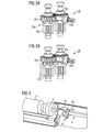
- FIGS. 3A and 3B show as an embodiment of the drive of the first push bar (rack) 4 serving transmission components a couplable worm drive 25 in the engaged ( Fig. 3A ) or disengaged state ( Fig. 3B ).
- the worm drive comprises a worm 25a with toothed shaft, which is mounted in a thrust bearing 25b and driven by a (not shown here) driven gear of the planetary gear.
- With the worm 25a are two worm gears 25c with spiral teeth in engagement, each associated with a dog clutch 25d.
- Fig. 4 shows an alternative implementation of this, namely taking up the notation in Fig. 1 ,
- the rack 4 is driven by a spur gear 26 and two worms 27 which are pivotally mounted in a slotted guide 28.
- the rack 4 is driven by two engaging directly in their flanks pinion whose axes of rotation are perpendicular to the longitudinal extent of the rack. This drive concept is familiar to the person skilled in the art and therefore will not be described or described in detail here.
- Fig. 5 shows in perspective view as an exemplary embodiment, the second Austriebsstange 5.
- This has at its one end (in the figure on the left) an engagement member 5a, which is here designed as a polygon, for engagement in a corresponding shaped engagement means on the sprouting piston 11 ( Fig. 1 ), which is a separate part from the Austriebsstange and, for example, belong to the cartridge 3.1 and can be supplied with this.
- the opposite end portion 5b of the Austriebsstange 5 has a spiral toothing with a great pitch, which provides a non-self-locking behavior.
- the Austriebsstange or spindle 5 is mounted on bearings 30. Between the end provided with the engagement element 5a and the spiral-toothed end section 5b, it is designed as a cylindrical axis and carries therein Area a follower braking device 31 for generating a minimum braking torque (in the range 0.5 to 1.0Nm), which also generates an axial feed in idle, ie in non-engaged state of the Austriebsstange with the associated Austriebkolben.
- the brake element 31 may otherwise serve as a position marker for identifying the axial position of the Austriebsstange in the field of view of an operator or against an optical detection device or carry such a marking element.
- FIG. 6 shows in a sectional view again essential parts of the gear unit 8 with the inserted Austriebsstangen 4 and 5, to illustrate their position assignment.
- the construction is opposite to in FIG Fig. 2 such as FIGS. 3A and 3B sketched transmission component 25 slightly modified; but this is immaterial to the understanding of this aspect of the construction of the drive device.
- Figs. 7A and 7B show this already in Fig. 5 illustrated brake element 31, which is designed here as a follower wrap spring housing, a little closer, and also the wrap spring 31a can be seen.
- Fig. 7B shows an embodiment of the braking element as a revolving plastic brake 31 '. Both brake element constructions are known per se to the person skilled in the art and will therefore not be explained further here.
- Fig. 8 shows on a block diagram schematically the structure of a sensor and associated control technology of the proposed drive device.
- the sensor system includes the on / off switch ("trigger") 13a, which serves primarily as the control element or - in addition to the latter or in sensory replacement thereof - a current detection unit 32 for detecting the motor current of the drive motor 9, the latter is provided via a motor drive 33.
- the drive control unit 14 includes a sensor signal processing stage 14a, a delay element 14b and a control signal output stage 14c.
- the signals from the microswitch 12, which ultimately contain information about the expulsion of the component A are appropriately related to data coming from the on / off switch 13a or the current detection unit 32 and finally contain information about the operating state of the engine.
- the processing result is subjected to a suitable time evaluation (also due to stored algorithms) in the delay element 14b, and as a result a suitable motor drive signal is output by the control signal output unit 14c in all operating situations of the application device.
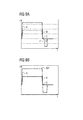
- Figs. 9A and 9B show exemplary timings based on motor current-time diagrams, each beginning at a point A with the increase of the detected motor current I due to a turn-on of the on / off switch 13a.
- the on / off switch is slowly released;
- the current detection unit 32 detects a motor current value of 0, then during a short phase D, the sensor signal processing unit 14a checks whether the motor current remains at 0 to determine whether the on / off switch has been deliberately or accidentally released. If the former is the case, then, at the point E, a signal from the still-pressed microswitch 12 can be processed such that the control signal output unit 14c ultimately outputs a signal causing the return of the motor 9.
- Fig. 9B shows an alternative implementation of a similar control flow.
- the motor current value is detected and stored in the sensor signal processing unit 14a before time B (release of the on / off switch) in a phase AB * and used for comparison with the current value measured at time C.
- the processing unit recognizes the result of the comparison when the on / off switch has been deliberately released, and starts, if the microswitch 12 has a corresponding signal, the motor return at virtually the same time.
Landscapes
- Engineering & Computer Science (AREA)
- Mechanical Engineering (AREA)
- Chemical Kinetics & Catalysis (AREA)
- Health & Medical Sciences (AREA)
- Chemical & Material Sciences (AREA)
- Dentistry (AREA)
- Life Sciences & Earth Sciences (AREA)
- Animal Behavior & Ethology (AREA)
- General Health & Medical Sciences (AREA)
- Public Health (AREA)
- Veterinary Medicine (AREA)
- Epidemiology (AREA)
- Oral & Maxillofacial Surgery (AREA)
- Coating Apparatus (AREA)
- Transmission Devices (AREA)
- Mixers With Rotating Receptacles And Mixers With Vibration Mechanisms (AREA)
- Accessories For Mixers (AREA)
Abstract
Antriebseinrichtung (1B) einer Dosier- und Mischvorrichtung (1A) für Mehrkomponentenstoffe, insbesondere Mehrkomponenten-Klebstoffe, welche mindestens zwei Kartuschenaufnahmevorrichtungen (2, 3) zur Aufnahme von auswechselbaren Kartuschen (2.1, 3.1) mit einzelnen Stoffkomponenten, eine Austriebsvorrichtung zum gleichzeitigen Austreiben der Stoffkomponenten aus den Kartuschen durch Komponentenausgänge mit Hilfe von in die Kartuschenaufnahmevorrichtung bzw. Kartuschen eintauchende Austriebskolben (11, 16), wobei mindestens ein Austriebskolben (11) ein Gewinde aufweist, welches durch eine Drehung einen Vorwärtstrieb dieses Austriebskolbens erzeugen kann, und eine Mischvorrichtung (17) aufweist, welche mit den Komponentenausgängen verbunden ist, die ausgetriebenen Stoffkomponenten mischt und diese gemischt austrägt, mit einer Getriebeeinheit (8) zum Anschluss einer, insbesondere elektrischen, Antriebsmaschine (9) und einer spindelartigen Austriebsstange (5) des mit dem Gewinde versehenen Austriebskolbens, welche in einem, bezogen auf die Gebrauchslage, hinteren Teil ihrer Längserstreckung einen spiralverzahnten nicht selbsthemmenden Spindelabschnitt (5b) und am vorderen Ende ein Eingriffselement (5a) zum Eingreifen in den Austriebskolben aufweist, wobei die Getriebeeinheit ein Abtriebsrad (29) mit Innen-Spiralverzahnung aufweist, welche an die Spiralverzahnung des Spindelabschnitts angepasst ist.
Description
- Die Erfindung betrifft eine Antriebseinrichtung einer Dosier- und Mischvorrichtung für Mehrkomponentenstoffe, insbesondere Mehrkomponenten-Klebstoffe, welche mindestens zwei zusammenhängende Kartuschenaufnahmevorrichtungen zur Aufnahme von auswechselbaren Kartuschen mit einzelnen Stoffkomponenten, eine Austriebsvorrichtung zum gleichzeitigen Austreiben der Stoffkomponenten aus den Kartuschen durch Komponentenausgänge mit Hilfe von in die Kartuschenaufnahmevorrichtung bzw. Kartuschen eintauchende Austriebskolben, wobei mindestens ein Austriebskolben ein Gewinde aufweist, welches durch eine Drehung einen Vorwärtstrieb dieses Austriebskolbens erzeugen kann, und eine Mischvorrichtung aufweist, welche mit den Komponentenausgängen verbunden ist, die ausgetriebenen Stoffkomponenten mischt und diese gemischt austrägt.
- Eine Dosier- und Mischvorrichtung mit dem vorstehend genannten Aufbau ist Gegenstand der unveröffentlichten Europäischen Patentanmeldung Ihrer
2010-0052 - Vorbekannt ist aus der
DE 3233366 A1 eine ähnliche Dosier- und Mischvorrichtung zum Mischen einer Dental-Abdruckmasse. Diese Vorrichtung umfasst ein als Wegwerfteil ausgebildetes Rührwerk mit einem Basiskörper, welcher eine Mischkammer, mehrere voneinander gesondert in die Mischkammer mündende Zuführkanäle für die Komponenten der Abdruckmasse sowie eine Auslassöffnung für die gemischte Abdruckmasse aufweist. Das Rührwerk umfasst weiterhin einen in der Mischkammer drehbar angeordneten Rührer, der von einer Antriebsvorrichtung, an der das Rührwerk abnehmbar gehalten ist, angetrieben wird. Die Komponenten der Abdruckmasse sind in Vorratszylindern enthalten und werden durch Kolben in die Mischkammer eingeschoben und nach Mischung über die Auslassöffnung in den Abdrucklöffel hinein ausgeschoben. Mittels einer Steuerung kann die Vorschubgeschwindigkeit von Stellantrieben der Kolben variiert werden, so dass sowohl das die Abbindezeit der Abdruckmasse bestimmende Verhältnis der Kolbenvorschubgeschwindigkeit als auch den Gesamtvorschub beziehungsweise die Vorschubdauer und damit die Abdruckmassenmenge gesteuert werden kann. - Es ist Aufgabe der Erfindung, eine zuverlässige und präzise arbeitende Antriebseinrichtung für eine Dosier- und Mischvorrichtung der oben genannten Art bereitzustellen.
- Diese Aufgabe wird durch eine Antriebseinrichtung mit den Merkmalen des Anspruchs 1 gelöst. Zweckmäßige Fortbildungen des Erfindungsgedankens sind Gegenstand der abhängigen Ansprüche.
- Die Erfindung schließt die Überlegung ein, beim Antrieb einer Dosier- und Mischvorrichtung mit einem selbstschneidenden Antriebskolben sicherzustellen, dass jener Kolben während des Betriebs ständig in sicherer Kraftübertragungs-Verbindung mit einem Antriebsmotor steht. Sie schließt weiter die Überlegung ein, dies mittels eines spiralverzahnten nicht selbsthemmenden Spindelantriebs zu realisieren. Weiterhin gehört zur Erfindung der Gedanke des Vorsehens einer Getriebeeinheit, deren Abtriebsrad eine an die Verzahnung der Austriebsstange mit Spindelabschnitt angepasste Verzahnung hat. Außerdem schließt die Erfindung den Gedanken ein, am (in Gebrauchslage) vorderen Ende der besagten Austriebsstange ein Eingriffselement zum Eingreifen in den Austriebskolben vorzusehen.
- Mit der vorgeschlagenen Lösung wird insbesondere erreicht, dass eine Antriebskraft in den durch Drehung selbsttätig einen Vorwärtstrieb erzeugenden (insbesondere einen selbstschneidenden) Kolben selbsttätig eingekoppelt wird. Dies geschieht speziell und in vorteilhafter Weise erst dann, wenn beim parallelen Austrieb (mindestens) einer anderen Komponente, der mittels eines herkömmlichen Austriebskolbens erfolgt, eine vorbestimmte (Gegen-)Druckschwelle überschritten wird. Gemäß den Anforderungen vieler Anwendungsfälle wird so ein Austrieb derjenigen Komponente, die mit dem selbstschneidenden Kolben ausgetrieben wird, dann und solange unterbunden, wenn und solange nicht zugleich eine andere Komponente gefördert wird, die mit der erstgenannten zu vermischen ist. Zudem kann bei der Neubeladung der Dosier- und Mischvorrichtung die Austriebsstange des selbstschneidenden Kolbens durch einfaches Zurückschieben (ohne erheblichen Widerstand und ohne zusätzliche Manipulationen) wieder in ihre Ausgangsposition gebracht werden.
- Der hier vorgeschlagene Antrieb berücksichtigt insbesondere den Umstand, dass bei einer Dosier- und Mischvorrichtung der in Rede stehenden Art, mit (mindestens) einem durch Drehung selbsttätig einen Vorwärtstrieb erzeugenden Austriebskolben, für diesen keine nennenswerte Axialkraft, sondern lediglich ein hinreichender Drehmoment bereitgestellt werden muss. Im Prinzip muss die Axialkraft lediglich so groß sein, dass die Austriebsstange nicht den Kontakt mit dem Austriebskolben verliert.
- Im Hinblick auf die vorstehend erwähnten Überlegungen und vorteilhaften Wirkungen erscheint eine Ausführung als vorteilhaft, bei der der spiralverzahnte Spindelabschnitt eine große Steigung der Spiralverzahnung zwischen 45° und 65°, spezieller zwischen 50° und 61°, aufweist.
- In weiteren zweckmäßigen Ausführungen ist das Eingriffselement am Ende der Austriebsstange als Mehrkantelement, Torx- oder Klauenelement ausgebildet. Es ist natürlich zu gewährleisten, dass die Gestalt des Eingriffselements mit der Gestalt einer entsprechenden Aus- oder Anformung auf der (in Gebrauchslage) Rückseite des Austriebskolbens mindestens insoweit korrespondiert, als dies zur Übertragung der im Anwendungsfall geforderten Drehmomentbeträge erforderlich ist. Hierzu muss die geometrische Gestalt vom Eingriffselement und der Eingriffsöffnung nicht notwendigerweise identisch sein. In einer zweckmäßigen Ausgestaltung ist das Eingriffselement korrespondierend zu einer Eingriffseinrichtung am Austriebskolben selbstfindend ausgebildet. Hierdurch lassen sich "Leerlauf" Phasen des Antriebs und Schädigungen des Eingriffsbereichs des Austriebskolbens weitgehend vermeiden.
- In kostengünstiger und auch funktionsseitig vorteilhafter Ausführung bestehen die spindelartige Austriebsstange im Wesentlichen aus Stahl und der Eingriffsbereich des Austriebskolbens im Wesentlichen aus Kunststoff. Es sind aber auch andere Materialpaarungen möglich und für spezielle Anwendungen ggfs. sinnvoll; so kann die Spindel auch ganz oder teilweise aus einer Nichteisenlegierung, wie Messing oder Bronze oder einer Aluminiumlegierung, bestehen, und auch in den üblicherweise im wesentlichen aus Kunststoff gefertigten Austriebskolben kann ggfs. ein aus Metall gefertigtes Gegenstück zum Spindel-Eingriffselement eingesetzt sein.
- In ähnlicher Weise ist in einer weiteren Ausführung vorgesehen, dass die spindelartige Austriebsstange im Wesentlichen aus Stahl und das innen verzahnte Abtriebsrad im Wesentlichen aus Kunststoff bestehen. Auch hier sind andere Materialpaarungen, etwa gemäß den oben genannten Beispielen, möglich und u. U. sinnvoll.
- In einer weiteren vorteilhaften Ausführung ist vorgesehen, dass im vorderen Bereich der Austriebsstange, außerhalb des spiralverzahnten Spindelabschnitts, ein mitlaufendes Bremselement zur Gewährleistung einer Axialbewegung der Austriebsstange auch im Leerlauf vorgesehen ist. Die Besonderheiten der Dosier- und Mischeinrichtung, für die die vorgeschlagene Antriebseinrichtung bestimmt ist, sichern zwar die Bereitstellung einer Axialkraft (Austriebskraft) unter Last, also im in den Austriebskolben eingekoppelten Zustand der Austriebsspindel. Es sind jedoch zusätzliche Mittel vorzusehen, um auch im Leerlauf der Antriebseinrichtung eine Axialbewegung zu erzeugen, die letztlich auch dazu führt, dass die Austriebsstange den Austriebskolben überhaupt findet. Das erwähnte Bremselement stellt dies sicher.
- In einer ersten Ausgestaltung ist das mitlaufende Bremselement als mitlaufende Kunststoffbremse ausgebildet. Eine weitere Ausführung zeichnet sich dadurch aus, dass das mitlaufende Bremselement als mitlaufendes Schlingfedergehäuse ausgebildet ist.
- Da im praktischen Betrieb der Dosier- und Mischvorrichtung feststellbar sein soll, ob der mit dem Gewinde versehene Austriebskolben korrekt arbeitet, also tatsächlich vorgeschoben wird und hierdurch die entsprechende Komponente austrägt, weist eine weitere Ausführung auf der Austriebsstange des mit dem Gewinde versehenen Austriebskolbens ein Positionsmarkierungselement zur, insbesondere optischen, Erfassung der axialen Position der Austriebsstange und somit indirekt des Austriebskolbens auf. In einer der vorgenannten Ausführungs-Aspekte sinnvoll kombinierenden Variante ist vorgesehen, dass das Positionsmarkierungselement durch das Mitlaufen des Bremselements gebildet oder an diesem angebracht ist.
- In einer weiteren Ausführung der Erfindung ist, die Getriebeeinheit als Planetengetriebeeinheit (der Antriebsmaschine) ausgebildet, die ein primäres Abtriebsrad umfasst. Weiter ist bevorzugt eine schaltbare Kupplungseinrichtung vorgesehen, die dann in vorteilhafter Weise ein Kupplungselement mit einem Antriebsritzel, welches mit dem primären Abtriebsrad im Eingriff steht, und ein weiteres Kupplungselement umfasst, welches als das innen verzahnte Abtriebsrad der Getriebeeinheit ausgebildet ist.
- Die weiter oben bereits erwähnte wünschenswerte Bindung des Austrags der mit dem selbstschneidenden Austriebskolben ausgetriebenen Komponente an das gleichzeitige Austreiben (mindestens) einer weiteren Komponente wird besonders verlässlich in einer weiteren Ausführung der Erfindung realisiert. Bei dieser ist die Getriebeeinheit zum Antrieb des mit dem Gewinde versehenen Austriebskolbens und mindestens eines weiteren, über eine Zahnstange angetriebenen Austriebskolbens einer anderen Komponente ausgebildet, und sie hat eine unter Gegendruck beim Austreiben der anderen Komponente axial verschiebliche Getriebebaugruppe. Hierbei ist das eine Kupplungselement der schaltbaren Kupplungseinrichtung in axialer Richtung im Wesentlichen fest bezüglich der verschieblichen Baugruppe positioniert, derart, dass es sich unter dem Gegendruck beim Austrag der anderen Komponente mit jener Baugruppe verschiebt. Hierdurch kommt das erste Kupplungselement in Eingriff mit dem anderen, fest bezüglich des Gerätegehäuses angeordneten Kupplungselement.
- Im Bereich der vorliegenden Erfindung liegt schließlich auch ein Applikationsgerät für Mehrkomponentenstoffe, insbesondere Mehrkomponenten-Klebstoffe, mit einer Antriebseinrichtung nach einem der vorangehenden Ansprüche, mit einer integrierten elektrischen Antriebsmaschine und Akku-Stromversorgung für diese sowie einer Bedien- und Steuereinheit.
- Im Folgenden wird die Erfindung anhand der bevorzugten Ausführungsbeispiele mit Hilfe der Figuren näher beschrieben, wobei nur die zum Verständnis der Erfindung notwendigen Merkmale dargestellt sind. Selbstverständlich ist die Erfindung nicht auf gezeigte und beschriebene Ausführungsbeispiele beschränkt.
- Es zeigen im Einzelnen:
- Fig. 1
- eine Seitenansicht eines erfindungsgemäßen Applikationsgerätes für einen 2-Komponentenkleber;
- Fig. 2
- eine Darstellung des Aufbaus der Getriebeeinheit 8 des Applikationsgerätes nach
Fig. 1 , - Fig. 3A und 3B
- perspektivische Darstellungen einer Ausführungsform von dem Antrieb der Zahnstange 4 dienenden Getriebekomponente,
- Fig. 4
- eine Prinzipskizze (in Art einer perspektivischen Darstellung) zur Erläuterung einer weiteren Variante des Antriebs der Zahnstange 4,
- Fig. 5
- eine perspektivische Darstellung einer Ausführungsform der zweiten Austriebsstange 5 des Applikationsgerätes nach
Fig. 1 , - Fig. 6
- eine Schnittansicht einer Ausführungsform der Getriebeeinheit 8 des Applikationsgerätes nach
Fig. 1 , - Fig. 7A und 7B
- Prinzipskizzen (in Art perspektivischer Darstellungen) eines Details der zweiten Austriebsstange nach
Fig. 5 , - Fig. 8
- ein Blockschaltbild einer Ausführungsform der zur Antriebseinrichtung 1B des Applikationsgerätes nach
Fig. 1 gehörenden Sensorik und - Fig. 9A und 9B
- Motorstrom-Zeit-Diagramme zu Erläuterung zweier Ausführungsformen eines Steuerungsablaufs der Antriebssteuerung.
-
Fig. 1 zeigt eine Seitenansicht (in schematisierter Darstellung) eines erfindungsgemäßen Applikationsgerätes 1, wobei als wesentliche Komponenten eine Dosier- und Mischvorrichtung 1A und eine zugehörige Antriebseinrichtung 1B und schließlich ein Gerätekörper 1C gesondert bezeichnet sind. - Die Dosier- und Mischvorrichtung 1A umfasst beispielhaft dargestellt zwei Kartuschenaufnahmevorrichtungen 2 und 3 unterschiedlichen Durchmessers und unterschiedlicher Länge für einen Schlauchbeutel 2.1 und eine feste Kartusche 3.1 Die größere Kartuschenaufnahmevorrichtung 2 wird mit Hilfe eines axial verschieblichen ersten Antriebskolbens ("Linearkolbens") 16 betätigt, der mit einer ersten Antriebsstange (Zahnstange) 4 verbunden ist und durch diese linear in die Kartuschenaufnahmevorrichtung 2 vorgetrieben wird. Die Kartuschenaufnahmevorrichtung 3, die einen wesentlich kleineren Durchmesser aufweist und außerdem wesentlich kürzer als die Kartuschenaufnahmevorrichtung 2 ist, wird erfindungsgemäß durch einen zweiten Antriebskolben ("Drehkolben") betätigt, welcher auf der Außenseite ein Gewinde aufweist, das sich in die Innenwandung der Kartuschenaufnahmevorrichtung 3 oder einer dort eingesetzten Kartusche 3.1 einprägt und durch seine Rotation einen Vortrieb erzeugt.
- Die Antriebseinheit 1B umfasst eine Getriebeeinheit 8, welche bei einer einzigen Antriebseingangsseite drei unterschiedliche Antriebsausgangsseiten aufweist. Dies sind einerseits ein Ausgang für die linear vorgeschobene Zahnstange 4, andererseits ein Ausgang für eine zweite Antriebsstange 5 und schließlich ein Ausgang für eine ebenfalls rotierende Antriebswelle 10, welche einen Rotationsmischer 7 betreibt. Die beiden Kartuschenaufnahmevorrichtungen 2 und 3 sind ausgangsseitig mit einer Kartuschenkupplung 6 verbunden, durch die auch das in den Kartuschenaufnahmevorrichtungen 2 und 3 befindliche Material von den Komponentenausgängen zum Rotationsmischer 7, der ebenfalls mit der Kartuschenkupplung 6 verbunden ist, befördert wird. Die Bauweise eines solchen Rotationsmischers ist bekannt. Er verfügt über eine vorne angebrachte Austriebsspitze 17, durch welche das gemischte Material letztendlich ausgetragen wird.
- Die Getriebeeinheit 8 wird in der hier gezeigten Ausführungsform der Dosier- und Mischvorrichtung 1 mit Hilfe eines Elektromotors 9 angetrieben. In ihr ist im übrigen ein Mikroschalter 12 vorgesehen, dessen Funktion weiter unten beschrieben wird. Der Gerätekorpus 1C umfasst im wesentlichen eine Bedieneinheit 13 mit einem manuell zu betätigenden Ein-/Ausschalter 13a, eine Betriebssteuereinheit 14 und einen Akkupack 15.
-
Fig. 2 zeigt den Aufbau einer Ausführungsform der Getriebeeinheit 8 etwas genauer; es wird hierzu auch aufFig. 6 und die Ausführungen weiter unten hingewiesen. Es ist zu beachten, dass die Darstellungsweise vonFig. 2 und weiteren Figuren insofern von derjenigen inFig. 1 abweicht, als inFig. 2 die zur Zahnstange 4 gehörenden Getriebekomponenten unten und die zur zweiten Austriebsstange 5 gehörenden Komponenten oben liegen. - Die Getriebeeinheit 8 umfasst eine erste, bezüglich einer Gehäusewandung 17 des Applikationsgerätes ortsfeste Baugruppe 18 und eine zweite, im Gerätegehäuse verschieblich gelagerte Baugruppe 19. Beide Getriebebaugruppen 18 und 19 sind durch eine (hier symbolisch dargestellte) Gegendruckfeder 20 elastisch gegeneinander verspannt, und die verschiebliche Baugruppe 19 ist gegenüber dem Gerätegehäuse 17 mit einem weiteren Federelement 21 elastisch abgestützt, welches im weiteren auch als Andruckfederelement bezeichnet wird. Die erste Baugruppe 18 umfasst ein Planetengetriebe 22, welches mit einem (nicht dargestellten) Antriebsritzel des Antriebsmotors im Eingriff steht, sowie den Abtrieb 23 zum Antrieb der spindelartigen zweiten Antriebsstange (hier ebenfalls nicht dargestellt) und Abtriebsräder für die erste Austriebstange (Zahnstange) und die Antriebswelle des Mischers, die hier ebenfalls nicht gesondert bezeichnet bzw. dargestellt sind.
- Am Abtrieb für die zweite Austriebsstange ist eine schaltbare Kupplung (Klauenkupplung) 24 vorgesehen, die ein bezüglich der ersten Baugruppe 28 ortsfestes erstes Kupplungselement 24a und ein bezüglich der zweiten Baugruppe 19 ortsfestes zweites Kupplungselement 24b umfasst. Eine in der zweiten Baugruppe 19 untergebrachte Getriebekomponente 25 zum Antrieb der ersten Austriebstange (Zahnstange) wird weiter unten beschrieben.
- An der ersten Baugruppe 18 ist der Mikroschalter 12 fest angebracht, der konstruktiv so ausgestaltet und positioniert ist, dass er in einer vorbestimmten Verschiebungsposition der zweiten Baugruppe 19 betätigt wird.
- Die Funktion der zweiteiligen Ausführung der Getriebeeinheit 8 mit den erwähnten Federabstützungen und dem Mikroschalter ist, vereinfacht erläutert, wie folgt:
- Im ausgeschalteten Zustand des Applikationsgerätes ist die zweite Baugruppe 19 gegenüber der ersten Baugruppe 18 der Getriebeeinheit 8 durch die Kraft der Gegendruckfeder 20 so weit verschoben, dass das erste und zweite Kupplungselement 24a, 24b der schaltbaren Kupplung 24 außer Eingriff sind und die zweite Baugruppe auch den Mikroschalter 12 nicht berührt. Die genaue Ruheposition der zweiten Baugruppe 19 wird durch geeignete Auswahl der Gegendruckfeder 20 und Andruckfeder 21 in Abstimmung aufeinander eingestellt, ebenso wie das Ansprechverhalten der Lagerung der zweiten Baugruppe bei Inbetriebnahme des Gerätes.
- Bei Inbetriebnahme gelangt die Antriebskraft vom Antriebsmotor über das Planetengetriebe 22 und die Getriebekomponente 25 auf die Zahnstange 4 und bewirkt deren Verschiebung in Austreibrichtung der Dosier- und Mischvorrichtung (in
Fig. 1 und Fig. 2 nach links). Sobald der erste Austriebskolben 16 auf das ihm zugewandte Ende der gefüllten Kartusche 2.1 trifft, baut sich aufgrund der Viskosität der darin enthaltenen Materialkomponente Reaktionsdruck auf, welcher über die Zahnstange 4 auf deren Antriebsritzel (vgl.Fig. 3A ) gelangt und über deren Lager auf die zweite Baugruppe 19 übertragen wird. Sie bewirkt eine Verschiebung der zweiten Baugruppe 19 gegenüber der ersten Baugruppe 18, entgegen der Federkraft der Gegendruckfeder 20. Sobald ein bestimmter Verschiebungsbetrag erreicht ist, kommen die Kupplungselemente 24a, 24b in Eingriff, und der Kraftfluss vom Antriebsmotor gelangt nun auch zur spindelartigen zweiten Austriebsstange 5, wodurch diese in Drehung versetzt wird und den selbstschneidenden Kolben antreibt. Zugleich wird durch die Verschiebung der zweiten Baugruppe 19 der Mikroschalter 12 betätigt; zu der mit diesem Vorgang verbundenen Funktion siehe weiter unten. - Durch diese Konstruktion und den hierdurch bewirkten Ablauf wird sichergestellt, dass ein Austreiben der in der Kartusche 3.1 enthaltenen Komponente B nur dann erfolgt, wenn auch die in der Kartusche 2.1 enthaltene Komponente A eines Mehrkomponentensystems ausgetrieben wird. Dies gilt auch dann, wenn eine bereits teilweise geleerte Kartusche zu Punkt 1 mit der Komponente A in das Gerät eingesetzt und der Betrieb in der voll zurückgezogenen Ausgangsposition der Zahnstange 4 gestartet wird. Diese läuft dann nämlich solange im Leerlauf nach vorn, und die zweite Getriebebaugruppe 19 bleibt in dem gegenüber der ersten Baugruppe 18 verschobenen Ausgangszustand, bis der erste Austriebskolben 16 auf das Ende der nur teilweise gefüllten Kartusche trifft. Erst zu diesem Zeitpunkt wird dort eine Reaktionskraft aufgebaut, die die zweite Baugruppe 19 an die erste Baugruppe 18 andrückt, hiermit die schaltbare Kupplung 24 schließt, wodurch die Antriebskraft auch in die zweite Austriebsstange (Spindel) 5 eingeleitet wird. Auch in diesem Anwendungsfall wird also Komponente B erst zum richtigen Zeitpunkt ausgetrieben.
-
Fig. 3A und 3B zeigen als Ausführungsform von dem Antrieb der ersten Austriebsstange (Zahnstange) 4 dienenden Getriebekomponenten einen koppelbaren Schneckentrieb 25 im eingekuppelten (Fig. 3A ) bzw. ausgekuppelten Zustand (Fig. 3B ). Der Schneckentrieb umfasst eine Schnecke 25a mit Zahnwelle, die in einem Axiallager 25b gelagert ist und über ein (hier nicht dargestellt) Abtriebsrad des Planetengetriebes angetrieben wird. Mit der Schnecke 25a stehen zwei Schneckenräder 25c mit Spiralverzahnung im Eingriff, denen jeweils eine Klauenkupplung 25d zugeordnet ist. Mit dem ausrückbaren Kupplungselement dieser Kupplung 25d ist jeweils eine geradverzahntes Antriebsritzel 25e fest verbunden, welches im eingerückten Zustand der Kupplung 25d mit dem Schneckenrad 25c mitläuft und die Antriebskraft auf die mit ihm im Eingriff stehende, hier nicht dargestellte Zahnstange (Ziffer 4 inFig. 1 ) überträgt. In dem inFig. 3B ausgekuppelten Zustand drehen die Ritzel 25e hingegen im wesentlichen frei, so dass die zwischen ihnen gelagerte und mit ihnen im Eingriff stehende Zahnstange praktisch widerstandsfrei axial verschoben werden kann. Dies ermöglicht ein leichtes Zurückziehen zur Neubeladung des Applikationsgerätes mit einer gefüllten Kartusche 2.1 (Fig. 1 ). -
Fig. 4 zeigt eine alternative Realisierung hierfür, und zwar unter Aufgreifen der Bezeichnungsweise inFig. 1 . Hier wird die Zahnstange 4 über ein Stirnradgetriebe 26 und zwei Schnecken 27 angetrieben, welche in einer Kulissenführung 28 schwenkbar gelagert sind. Durch Verschwenken der Schnecken 27 mittels eines nicht dargestellten Betätigungshebels ist ihr Eingriff mit der Zahnstange 4 aufhebbar, wodurch es wiederum ermöglicht wird, die Zahnstange nahezu widerstandsfrei zurückzuziehen. In weiterer Abwandlung des Aufbaus dieses Getriebeteils kann auch vorgesehen sein, dass die Zahnstange 4 über zwei direkt in ihrer Flanken eingreifende Ritzel angetrieben wird, deren Rotationsachsen senkrecht zur Längserstreckung der Zahnstange stehen. Dieses Antriebskonzept ist dem Fachmann vertraut und wird daher hier nicht genauer dargestellt oder beschrieben. -
Fig. 5 zeigt in perspektivischer Darstellung als Ausführungsbeispiel die zweite Austriebsstange 5. Diese hat an ihrem einen Ende (in der Figur links) ein Eingriffselement 5a, welches hier als Mehrkant ausgebildet ist, zum Eingriff in eine korrespondierende geformte Eingriffseinrichtung am Austriebskolben 11 (Fig. 1 ), der gegenüber der Austriebsstange ein separates Teil darstellt und beispielsweise zur Kartusche 3.1 gehören und mit dieser geliefert werden kann. Der gegenüberliegende Endabschnitt 5b der Austriebsstange 5 weist eine Spiralverzahnung mit großer Steigung auf, welche ein nicht selbsthemmendes Verhalten erbringt. In diesem Endabschnitt 5b steht die spindelartige Austriebsstange mit einem korrespondierend zum Außengewinde des Abschnitts 5b innenverzahnten Antriebsrad 29 der Getriebeeinrichtung im Eingriff, welches mit dem weiter oben beschriebenen zweiten Kupplungselement 24b der inFig. 2 gezeigten schaltbaren Kupplung 24 fest verbunden oder einstückig geformt ist. - Die Austriebsstange bzw. Spindel 5 ist an Lagerstellen 30 gelagert. Zwischen dem mit dem Eingriffselement 5a versehenen Ende und dem spiralverzahnten Endabschnitt 5b ist sie als zylindrische Achse gestaltet und trägt in diesem Bereich eine mitlaufende Bremseinrichtung 31 zur Erzeugung eines minimalen Bremsmoments (im Bereich 0,5 bis 1,0Nm), welches einen axialen Vorschub auch im Leerlauf, d.h. also im eingriffslosen Zustand der Austriebsstange mit dem zugehörigen Austriebkolben, erzeugt. Das Bremselement 31 kann im übrigen als Positionsmarker zur Kennzeichnung der axialen Position der Austriebsstange im Blickfeld eines Bedieners oder gegenüber einer optischen Erfassungseinrichtung dienen oder ein solches Markierungselement tragen. Damit lässt sich erfassen ob die zweite Austriebsstange sich (ebenso wie die erste Austriebsstange) vorwärts bewegt, also ein korrektes Austreiben der Komponente B erfolgt. Ein Versagen (etwa bedingt dadurch, dass kein korrekter Eingriff zwischen der Austriebsstange und dem separaten Austriebskolben besteht) kann hierdurch ohne weiteres erkannt und das Auftreten schadhafter Klebestellen unterbunden werden.
-
Fig. 6 zeigt in einer Schnittansicht nochmals wesentliche Teile der Getriebeeinheit 8 mit den eingesetzten Austriebsstangen 4 und 5, um deren Positionszuordnung zu verdeutlichen. Hinsichtlich des Schneckentriebs 25' zum Antrieb der ersten Austriebsstange 4 ist die Konstruktion gegenüber der inFig. 2 sowieFig. 3A und 3B skizzierten Getriebekomponente 25 etwas modifiziert; dies ist aber für das Verständnis dieses Aspekts der Konstruktion der Antriebseinrichtung unwesentlich. -
Fig. 7A und 7B zeigen zum einen das bereits inFig. 5 dargestellte Bremselement 31, welches hier als mitlaufendes Schlingfedergehäuse ausgeführt ist, etwas genauer, und auch die Schlingfeder 31a ist zu sehen.Fig. 7B zeigt eine Ausführung des Bremselements als mitlaufende Kunststoffbremse 31'. Beide Bremselement-Konstruktionen sind dem Fachmann an sich bekannt und werden daher hier nicht weiter erläutert. -
Fig. 8 zeigt an einem Blockschaltbild schematisch den Aufbau einer Sensorik und mit dieser verbundenen Steuerungstechnik der vorgeschlagenen Antriebseinrichtung. Die Sensorik umfasst neben dem bereits erwähnten Mikroschalter 12 den natürlich primär als Bedienelement dienenden Ein-/Ausschalter ("Trigger") 13a bzw. - zusätzlich zu letzterem oder in sensorischer Ersetzung desselben - eine Stromerfassungseinheit 32 zur Erfassung des Motorstromes des Antriebsmotors 9, der diesem über eine Motoransteuerung 33 bereitgestellt wird. Die Antriebssteuereinheit 14 umfasst ein Sensorsignal-Verarbeitungsstufe 14a, ein Verzögerungsglied 14b und eine Steuersignal-Ausgangsstufe 14c. - Über einen in der Sensorsignal-Verarbeitungseinheit 14a implementierten Verarbeitungsalgorithmus werden die Signale vom Mikroschalter 12, die letztlich eine Information über das Austreiben der Komponente A beinhalten, in geeignete Beziehung gesetzt zu Daten, die vom Ein-/Ausschalter 13a oder der Stromerfassungseinheit 32 kommen und letztlich eine Information zum Betriebszustand des Motors beinhalten. Das Verarbeitungsergebnis wird im Verzögerungsglied 14b noch einer geeigneten zeitlichen Bewertung (ebenfalls aufgrund gespeicherter Algorithmen) unterzogen, und im Ergebnis wird durch die Steuersignal-Ausgabeeinheit 14c in allen Betriebsituationen des Applikationsgerätes ein geeignetes Motoransteuersignal ausgegeben.
-
Fig. 9A und 9B zeigen beispielhafte Zeitabläufe anhand von Motorstrom-Zeit-Diagrammen, die jeweils an einem Punkt A mit dem Ansteigen des erfassten Motorstromes I aufgrund einer Einschaltbetätigung des Ein-/Ausschalters 13a beginnen. Am Punkt B inFig. 9A wird der Ein-/Ausschalter langsam losgelassen; am Punkt C erfasst die Stromerfassungseinheit 32 einen Motorstrom-Wert von 0, danach während einer kurzen Phase D prüft die Sensor-Signalverarbeitungseinheit 14a, ob der Motorstrom beim Wert 0 bleibt, um festzustellen, ob der Ein-/Ausschalter bewusst oder versehentlich losgelassen wurde. Ist ersteres der Fall, kann danach, am Punkt E, ein Signal vom noch gedrückten Mikroschalter 12 derart verarbeitet werden, dass die Steuersignal-Ausgabeeinheit 14c letztlich ein den Rücklauf des Motors 9 bewirkendes Signal ausgibt. -
Fig. 9B zeigt eine alternative Realisierung eines vergleichbaren Steuerungs-Ablaufes. Hierbei wird in der Sensorsignal-Verarbeitungseinheit 14a vor dem Zeitpunkt B (Loslassen des Ein-/Ausschalters) in einer Phase AB* der Motorstromwert erfasst und gespeichert und für einen Vergleich mit dem zum Zeitpunkt C gemessenen Stromwert herangezogen. Hier erkennt die Verarbeitungseinheit am Vergleichsergebnis, wenn der Ein-/Ausschalter bewusst losgelassen wurde, und startet, sofern vom Mikroschalter 12 ein entsprechendes Signal vorliegt, den Motorrücklauf zum praktisch gleichen Zeitpunkt. - Mit dem in beiden Varianten beschriebenen Vorgehen soll ein unnötiger MotorRücklauf bei versehentlichem oder nur sehr kurzzeitigem Loslassen des Triggers verhindert, zugleich aber ein aufgrund einer bewussten Beendigung des Austreibvorganges sinnvoll werdender Rücklauf eingeleitet werden, mit dem ein "überschießendes" Austreiben von Mehrkomponentenstoffen, insbesondere der Komponente A (die ja bei einfachem Ausschalten des Motors noch unter Austreibdruck stünde), unterbunden werden. Zugleich wird mit dem (geringfügigen) Rücklauf und mit der Beendigung der Wirkung der von der Komponente A ausgehenden Reaktionskraft erreicht, dass die zweite Getriebebaugruppe 19 in ihrer von der ersten Baugruppe 18 maximal beabstandete Ausgangsstellung zurückwandert, hiermit die Kupplung 24 gelöst wird und der Mikroschalter 12 freigegeben wird. Dies ist ein geeigneter Ausschalt- und Nichtgebrauchszustand des Applikationsgerätes.
- Die Ausführung der Erfindung ist nicht auf diese Beispiele beschränkt, sondern ebenso in einer Vielzahl von Abwandlungen möglich, die im Rahmen fachgemäßen Handelns liegen.
Claims (14)
- Antriebseinrichtung (1B) einer Dosier- und Mischvorrichtung (1A) für Mehrkomponentenstoffe, insbesondere Mehrkomponenten-Klebstoffe, welche mindestens zwei Kartuschenaufnahmevorrichtungen (2, 3) zur Aufnahme von auswechselbaren Kartuschen (2.1, 3.1) mit einzelnen Stoffkomponenten, eine Austriebsvorrichtung zum gleichzeitigen Austreiben der Stoffkomponenten aus den Kartuschen durch Komponentenausgänge mit Hilfe von in die Kartuschenaufnahmevorrichtung bzw. Kartuschen eintauchende Austriebskolben (11, 16), wobei mindestens ein Austriebskolben (11) ein Gewinde aufweist, welches durch eine Drehung einen Vorwärtstrieb dieses Austriebskolbens erzeugen kann, und eine Mischvorrichtung (17) aufweist, welche mit den Komponentenausgängen verbunden ist, die ausgetriebenen Stoffkomponenten mischt und diese gemischt austrägt, mit
einer Getriebeeinheit (8) zum Anschluss einer, insbesondere elektrischen, Antriebsmaschine (9) und
einer spindelartigen Austriebsstange (5) des mit dem Gewinde versehenen Austriebskolbens, welche in einem, bezogen auf die Gebrauchslage, hinteren Teil ihrer Längserstreckung einen spiralverzahnten nicht selbsthemmenden Spindelabschnitt (5b) und am vorderen Ende ein Eingriffselement (5a) zum Eingreifen in den Austriebskolben aufweist,
wobei die Getriebeeinheit ein Abtriebsrad (29) mit Innen-Spiralverzahnung aufweist, welche an die Spiralverzahnung des Spindelabschnitts angepasst ist. - Antriebseinrichtung nach Anspruch 1, wobei der spiralverzahnte Spindelabschnitt (5b) eine Steigung der Spiralverzahnung zwischen 45° und 65°, spezieller zwischen 50° und 61°, aufweist.
- Antriebseinrichtung nach Anspruch 1 oder 2, wobei die spindelartigen Antriebsstange (5) im Wesentlichen aus Stahl und das innen verzahnte Abtriebsrad (29) im Wesentlichen aus Kunststoff besteht.
- Antriebseinrichtung nach einem der vorangehenden Ansprüche, wobei im vorderen Bereich der Austriebsstange (5), außerhalb des spiralverzahnten Spindelabschnitts (5b), ein mitlaufendes Bremselement (31, 31') zur Gewährleistung einer Axialbewegung der Austriebsstange auch im Leerlauf vorgesehen ist.
- Antriebseinrichtung nach Anspruch 4, wobei das mitlaufende Bremselement (31') als mitlaufende Kunststoffbremse ausgebildet ist.
- Antriebseinrichtung nach Anspruch 4, wobei das mitlaufende Bremselement als mitlaufendes Schlingfedergehäuse (31) ausgebildet ist.
- Antriebseinrichtung nach einem der vorangehenden Ansprüche, wobei auf der spindelartigen Austriebsstange (5) ein Positionsmarkierungselement (31) zur, insbesondere optischen, Erfassung der axialen Position der Austriebsstange und somit indirekt des mit ihr im Eingriff stehenden Austriebskolbens (11) vorgesehen ist.
- Antriebseinrichtung nach Anspruch 7 und einem der Ansprüche 4 bis 6, wobei das Positionsmarkierungselement durch das mitlaufende Bremselement (31) gebildet oder an diesem angebracht ist.
- Antriebseinrichtung nach einem der vorangehenden Ansprüche, wobei das Eingriffselement (5a) am Ende der Austriebsstange (5) als Mehrkantelement, Torx- oder Klauenelement ausgebildet ist.
- Antriebseinrichtung nach Anspruch 9 wobei das Eingriffselement (5a) korrespondierend zu einer Eingriffseinrichtung am Austriebskolben selbstfindend ausgebildet ist.
- Antriebseinrichtung nach einem der vorangehenden Ansprüche, wobei die Getriebeeinheit (8) eine Planetengetriebeeinheit (22) der Antriebsmaschine mit einem primären Abtriebsrad (23) umfasst und eine schaltbare Kupplungseinrichtung (24) ein erstes Kupplungselement (24a) mit einem Antriebsritzel, welches mit dem primären Abtriebsrad im Eingriff steht, und ein zweites Kupplungselement (24b) umfasst, welches als das innen verzahnte Abtriebsrad (29) der Getriebeeinheit ausgebildet ist.
- Antriebseinrichtung nach Anspruch 9 oder 10, wobei die schaltbare Kupplungseinrichtung als Klauenkupplung (24) ausgebildet ist.
- Antriebseinrichtung nach Anspruch 11 oder 12, wobei
die Getriebeeinheit (8) zum Antrieb des mit dem Gewinde versehenen Austriebskolbens (11) und mindestens eines weiteren, über eine Zahnstange (4) angetriebenen Austriebskolbens (16) einer anderen Komponente ausgebildet ist und eine unter Reaktionsdruck beim Austragen der anderen Komponente axial verschiebliche Baugruppe (19) hat und
das zweite Kupplungselement (24b) der schaltbaren Kupplungseinrichtung (24) in axialer Richtung im Wesentlichen fest bezüglich der verschieblichen Baugruppe positioniert ist, derart, dass es sich unter dem Reaktionsdruck beim Austrag der anderen Komponente mit der Baugruppe verschiebt und hierdurch in Eingriff mit dem ersten Kupplungselement (24a) kommt. - Applikationsgerät (1) für Mehrkomponentenstoffe, insbesondere Mehrkomponenten-Klebstoffe, mit einer Antriebseinrichtung (1B) nach einem der vorangehenden Ansprüche, mit einer integrierten elektrischen Antriebsmaschine (9) und Akku-Stromversorgung (5) für diese sowie einer Bedien- und Steuereinheit (3, 4).
Priority Applications (11)
| Application Number | Priority Date | Filing Date | Title |
|---|---|---|---|
| EP11194922.8A EP2606986A1 (de) | 2011-12-21 | 2011-12-21 | Antriebseinrichtung einer Dosier- und Mischvorrichtung für Mehrkomponentenstoffe |
| BR112014014076A BR112014014076A2 (pt) | 2011-12-21 | 2012-12-12 | dispositivo de acionamento de um aparelho de medição e mistura |
| CN201280063197.2A CN104010737B (zh) | 2011-12-21 | 2012-12-12 | 用于多组分物质的计量及混合装置的驱动装置 |
| JP2014547850A JP6290787B2 (ja) | 2011-12-21 | 2012-12-12 | 計量混合機器の駆動装置 |
| AU2012358117A AU2012358117B2 (en) | 2011-12-21 | 2012-12-12 | Driving device of a metering and mixing apparatus for multi-component substances |
| EP12799193.3A EP2794122B1 (de) | 2011-12-21 | 2012-12-12 | Antriebseinrichtung einer dosier- und mischvorrichtung für mehrkomponentenstoffe |
| CA2858625A CA2858625C (en) | 2011-12-21 | 2012-12-12 | Driving device of a metering and mixing apparatus |
| PCT/EP2012/075192 WO2013092334A1 (de) | 2011-12-21 | 2012-12-12 | Antriebseinrichtung einer dosier- und mischvorrichtung für mehrkomponentenstoffe |
| DK12799193.3T DK2794122T3 (en) | 2011-12-21 | 2012-12-12 | A propulsion system Metering and mixing device FOR MULTIPLE COMPONENT SUBSTANCES |
| RU2014120531A RU2014120531A (ru) | 2011-12-21 | 2012-12-12 | Приводное устройство дозирующего смесительного аппарата |
| US14/311,968 US9381538B2 (en) | 2011-12-21 | 2014-06-23 | Driving device of a metering and mixing apparatus |
Applications Claiming Priority (1)
| Application Number | Priority Date | Filing Date | Title |
|---|---|---|---|
| EP11194922.8A EP2606986A1 (de) | 2011-12-21 | 2011-12-21 | Antriebseinrichtung einer Dosier- und Mischvorrichtung für Mehrkomponentenstoffe |
Publications (1)
| Publication Number | Publication Date |
|---|---|
| EP2606986A1 true EP2606986A1 (de) | 2013-06-26 |
Family
ID=47351672
Family Applications (2)
| Application Number | Title | Priority Date | Filing Date |
|---|---|---|---|
| EP11194922.8A Withdrawn EP2606986A1 (de) | 2011-12-21 | 2011-12-21 | Antriebseinrichtung einer Dosier- und Mischvorrichtung für Mehrkomponentenstoffe |
| EP12799193.3A Active EP2794122B1 (de) | 2011-12-21 | 2012-12-12 | Antriebseinrichtung einer dosier- und mischvorrichtung für mehrkomponentenstoffe |
Family Applications After (1)
| Application Number | Title | Priority Date | Filing Date |
|---|---|---|---|
| EP12799193.3A Active EP2794122B1 (de) | 2011-12-21 | 2012-12-12 | Antriebseinrichtung einer dosier- und mischvorrichtung für mehrkomponentenstoffe |
Country Status (10)
| Country | Link |
|---|---|
| US (1) | US9381538B2 (de) |
| EP (2) | EP2606986A1 (de) |
| JP (1) | JP6290787B2 (de) |
| CN (1) | CN104010737B (de) |
| AU (1) | AU2012358117B2 (de) |
| BR (1) | BR112014014076A2 (de) |
| CA (1) | CA2858625C (de) |
| DK (1) | DK2794122T3 (de) |
| RU (1) | RU2014120531A (de) |
| WO (1) | WO2013092334A1 (de) |
Cited By (3)
| Publication number | Priority date | Publication date | Assignee | Title |
|---|---|---|---|---|
| WO2016046094A1 (de) | 2014-09-23 | 2016-03-31 | Sika Technology Ag | Applikationsvorrichtung für stoffe |
| US10456804B2 (en) | 2014-09-23 | 2019-10-29 | Sika Technology Ag | Application device |
| CN111604000A (zh) * | 2020-06-30 | 2020-09-01 | 杨艳姣 | 针筒式定量调配装置 |
Families Citing this family (13)
| Publication number | Priority date | Publication date | Assignee | Title |
|---|---|---|---|---|
| EP2468416A1 (de) * | 2010-12-24 | 2012-06-27 | Sika Technology AG | Applikationsvorrichtung für Mehrkomponentenstoffe, ein Kartuschenset und eine Verpackungseinheit |
| EP2606985A1 (de) * | 2011-12-21 | 2013-06-26 | Sika Technology AG | Antriebseinrichtung einer Dosier- und Mischvorrichtung |
| EP2606986A1 (de) * | 2011-12-21 | 2013-06-26 | Sika Technology AG | Antriebseinrichtung einer Dosier- und Mischvorrichtung für Mehrkomponentenstoffe |
| US10124303B2 (en) * | 2014-09-05 | 2018-11-13 | Nordson Corporation | Apparatus and methods for dispensing small beads of viscous material |
| US9981233B2 (en) * | 2015-07-24 | 2018-05-29 | Phillip Phung-I HO | Portable mixer and dispenser for multi-component substances |
| CN107920882B (zh) * | 2015-08-19 | 2020-12-08 | 高露洁-棕榄公司 | 多化学品分配器 |
| EP3251755A1 (de) * | 2016-05-31 | 2017-12-06 | Sulzer Mixpac AG | Zweikomponentenspender |
| ES2664581B1 (es) * | 2016-09-20 | 2019-01-30 | Garcia Daniel Ortiz | Dispositivo mezclador y aplicador de sellantes |
| EP3589230B1 (de) * | 2017-03-01 | 2021-10-20 | Dentsply Sirona Inc. | Motorisierter spender |
| CN109365166B (zh) * | 2018-09-19 | 2020-07-17 | 宁波辰磁电子科技有限公司 | 一种打印机磁辊喷漆装置 |
| EP3666401A1 (de) * | 2018-12-14 | 2020-06-17 | Hilti Aktiengesellschaft | Verfahren zum betreiben eines auspresssystems und auspresssystem |
| WO2022016264A1 (en) * | 2020-07-21 | 2022-01-27 | Neild Innovations, Inc. | Method & device for injecting fluid into a liquid filled vessel under pressure |
| CN113578107B (zh) * | 2021-08-05 | 2024-07-23 | 重庆八零四零生物工程研究院有限公司 | 一种山药综合酵素加工用浆液混合调配装置 |
Citations (6)
| Publication number | Priority date | Publication date | Assignee | Title |
|---|---|---|---|---|
| EP0057465A2 (de) * | 1981-02-03 | 1982-08-11 | Gebrüder Kömmerling Kunststoffwerke GmbH | Hand-Mischpistole |
| DE3233366A1 (de) | 1982-02-05 | 1983-09-22 | Hans Klaus 8091 Ebrach Schneider | Vorrichtung zum mischen von dentalmassen |
| EP1279379A1 (de) * | 2001-07-26 | 2003-01-29 | Ernst Mühlbauer GmbH & Co.KG | Verfahren und Vorrichtung zum Erzeugen einer Mehrkomponentenmasse |
| WO2008076941A1 (en) * | 2006-12-15 | 2008-06-26 | 3M Innovative Properties Company | Mixing and dispensing curable multi-component materials |
| US20090039113A1 (en) * | 2007-08-09 | 2009-02-12 | Techway Industrial Co., Ltd | Electric caulking gun |
| WO2011025831A1 (en) * | 2009-08-28 | 2011-03-03 | 3M Innovative Properties Company | Device for dispensing a dental material |
Family Cites Families (36)
| Publication number | Priority date | Publication date | Assignee | Title |
|---|---|---|---|---|
| US3570719A (en) * | 1968-07-02 | 1971-03-16 | Louis Schiff | Reagent mixing and dispensing apparatus |
| CH562942A5 (de) * | 1972-06-08 | 1975-06-13 | Blieberger Rudolf | |
| JPS5458161A (en) * | 1977-10-19 | 1979-05-10 | Tsubakimoto Chain Co | Shaft fastening method for plastic gear of reduction gear |
| US4180187A (en) * | 1978-06-30 | 1979-12-25 | Ben Haim Haim | Automatic piston drive mechanism for use in caulking gun |
| US4322022A (en) * | 1980-03-19 | 1982-03-30 | Whirlco, Inc. | Quick release for helically-threaded drive unit |
| US4306671A (en) * | 1980-03-31 | 1981-12-22 | Fisher Arnold J | Portable motor driven dispenser |
| DE3128611C2 (de) * | 1981-07-20 | 1994-07-14 | Hilti Ag | Dosiergerät für Mehrkomponenten-Massen |
| DE3400726A1 (de) * | 1984-01-11 | 1985-07-18 | Horst 3000 Hannover Pudwill | Vorrichtung zum verpressen von dichtungsmasse oder dergleichen, insbesondere fugendichtungsmasse |
| EP0172788B1 (de) * | 1984-08-25 | 1988-05-18 | HILTI Aktiengesellschaft | Motorisch angetriebenes Handspritzgerät zum Verarbeiten von plastischen Massen |
| JPH07761Y2 (ja) * | 1987-05-08 | 1995-01-11 | 三菱農機株式会社 | クラッチ部の軸ブレ−キ装置 |
| DE3723517A1 (de) * | 1987-07-16 | 1989-01-26 | Licentia Gmbh | Handgefuehrtes, motorisch angetriebenes elektrowerkzeug |
| US4840294A (en) * | 1988-02-12 | 1989-06-20 | Illinois Tool Works Inc. | Adjustable dispensing tool |
| DE58900981D1 (de) * | 1988-07-13 | 1992-04-23 | Gurit Essex Ag | Verfahren zum ausstossen einer in einer kartusche enthaltenen substanz und einrichtung zur durchfuehrung des verfahrens. |
| US5104005A (en) * | 1988-11-10 | 1992-04-14 | Albion Engineering Company | Dual component mechanically operated caulking gun |
| DE59102231D1 (de) * | 1990-06-22 | 1994-08-25 | Wilhelm A Keller | Elektrisch betriebenes Austraggerät. |
| JPH081319Y2 (ja) * | 1991-06-05 | 1996-01-17 | 忠義 藤原 | 電動シリンダ |
| JPH0525338U (ja) * | 1991-09-13 | 1993-04-02 | 豊田工機株式会社 | トルクセンサ |
| US5207357A (en) * | 1992-02-13 | 1993-05-04 | Quikpoint, Inc. | Epoxy ejection gun |
| DE29501255U1 (de) * | 1995-01-27 | 1995-03-09 | Hilti Ag, Schaan | Folienbeutelpackung mit Folienbeutel und Bodenteil |
| JP2898899B2 (ja) * | 1995-02-14 | 1999-06-02 | 株式会社ナブコ | モータ駆動式液圧アクチュエータ |
| US5762239A (en) * | 1996-06-14 | 1998-06-09 | Cossette; Andre | Hand held scellant applicator |
| DE29706235U1 (de) * | 1997-04-08 | 1998-08-27 | Ernst Mühlbauer KG, 22547 Hamburg | Anordnung zum Ausgeben einer gemischten dentaltechnischen Mehrkomponentenmasse |
| AU9093298A (en) | 1997-09-16 | 1999-04-05 | Skyrad Ltd. | A dosimeter for sun radiation |
| DE29819661U1 (de) * | 1998-11-04 | 1999-02-25 | Kress-Elektrik GmbH & Co Elektromotorenfabrik, 72406 Bisingen | Vorrichtung zum Auspressen und dosierten Abgeben von fließfähigen Mehrkomponenten |
| DE10164385C1 (de) * | 2001-12-28 | 2003-03-06 | Kettenbach Gmbh & Co Kg | Vorrichtung zum Vermischen zweier pastöser Massen, insbesondere zum Vermischen einer Dental-Abformmasse mit einer Katalysatormasse |
| NL1026872C2 (nl) * | 2004-08-19 | 2006-02-21 | Bostik Findley B V | Kitpistool, bijbehorende verpakking met kitcomponent, mengeenheid en verbindingsstuk, en werkwijze voor gebruik daarvan. |
| JP2006231217A (ja) * | 2005-02-25 | 2006-09-07 | Tdk Corp | 塗布装置および磁気テープ製造装置 |
| DE102006038897B4 (de) * | 2006-08-18 | 2014-10-16 | Mühlbauer Technology Gmbh | Gerät zum Erzeugen einer Mehrkomponentenmasse |
| DE102007018143B3 (de) * | 2007-04-16 | 2008-06-05 | Kettenbach Gmbh & Co. Kg | Behälter und Verfahren zum Eröffnen eines Behälters |
| WO2009086650A1 (en) * | 2008-01-11 | 2009-07-16 | Medmix Systems Ag | Dispensing appliance for a multiple cartridge |
| JP2010127415A (ja) * | 2008-11-28 | 2010-06-10 | Fp Corporation Ltd | スクリュー釘 |
| EP2468416A1 (de) * | 2010-12-24 | 2012-06-27 | Sika Technology AG | Applikationsvorrichtung für Mehrkomponentenstoffe, ein Kartuschenset und eine Verpackungseinheit |
| EP2468415A1 (de) | 2010-12-24 | 2012-06-27 | Sika Technology AG | Dosier- und Mischvorrichtung für Mehrkomponentenstoffe |
| EP2606985A1 (de) * | 2011-12-21 | 2013-06-26 | Sika Technology AG | Antriebseinrichtung einer Dosier- und Mischvorrichtung |
| EP2606984A1 (de) * | 2011-12-21 | 2013-06-26 | Sika Technology AG | Antriebsvorrichtung einer Dosier- und Mischvorrichtung |
| EP2606986A1 (de) * | 2011-12-21 | 2013-06-26 | Sika Technology AG | Antriebseinrichtung einer Dosier- und Mischvorrichtung für Mehrkomponentenstoffe |
-
2011
- 2011-12-21 EP EP11194922.8A patent/EP2606986A1/de not_active Withdrawn
-
2012
- 2012-12-12 WO PCT/EP2012/075192 patent/WO2013092334A1/de not_active Ceased
- 2012-12-12 JP JP2014547850A patent/JP6290787B2/ja active Active
- 2012-12-12 EP EP12799193.3A patent/EP2794122B1/de active Active
- 2012-12-12 RU RU2014120531A patent/RU2014120531A/ru not_active Application Discontinuation
- 2012-12-12 CN CN201280063197.2A patent/CN104010737B/zh active Active
- 2012-12-12 DK DK12799193.3T patent/DK2794122T3/en active
- 2012-12-12 AU AU2012358117A patent/AU2012358117B2/en not_active Ceased
- 2012-12-12 BR BR112014014076A patent/BR112014014076A2/pt not_active IP Right Cessation
- 2012-12-12 CA CA2858625A patent/CA2858625C/en active Active
-
2014
- 2014-06-23 US US14/311,968 patent/US9381538B2/en active Active
Patent Citations (6)
| Publication number | Priority date | Publication date | Assignee | Title |
|---|---|---|---|---|
| EP0057465A2 (de) * | 1981-02-03 | 1982-08-11 | Gebrüder Kömmerling Kunststoffwerke GmbH | Hand-Mischpistole |
| DE3233366A1 (de) | 1982-02-05 | 1983-09-22 | Hans Klaus 8091 Ebrach Schneider | Vorrichtung zum mischen von dentalmassen |
| EP1279379A1 (de) * | 2001-07-26 | 2003-01-29 | Ernst Mühlbauer GmbH & Co.KG | Verfahren und Vorrichtung zum Erzeugen einer Mehrkomponentenmasse |
| WO2008076941A1 (en) * | 2006-12-15 | 2008-06-26 | 3M Innovative Properties Company | Mixing and dispensing curable multi-component materials |
| US20090039113A1 (en) * | 2007-08-09 | 2009-02-12 | Techway Industrial Co., Ltd | Electric caulking gun |
| WO2011025831A1 (en) * | 2009-08-28 | 2011-03-03 | 3M Innovative Properties Company | Device for dispensing a dental material |
Cited By (4)
| Publication number | Priority date | Publication date | Assignee | Title |
|---|---|---|---|---|
| WO2016046094A1 (de) | 2014-09-23 | 2016-03-31 | Sika Technology Ag | Applikationsvorrichtung für stoffe |
| US20170239683A1 (en) * | 2014-09-23 | 2017-08-24 | Sika Technology Ag | Application device for materials |
| US10456804B2 (en) | 2014-09-23 | 2019-10-29 | Sika Technology Ag | Application device |
| CN111604000A (zh) * | 2020-06-30 | 2020-09-01 | 杨艳姣 | 针筒式定量调配装置 |
Also Published As
| Publication number | Publication date |
|---|---|
| WO2013092334A1 (de) | 2013-06-27 |
| DK2794122T3 (en) | 2016-08-29 |
| AU2012358117B2 (en) | 2016-09-29 |
| CA2858625C (en) | 2019-08-06 |
| JP2015515359A (ja) | 2015-05-28 |
| BR112014014076A2 (pt) | 2017-06-13 |
| CA2858625A1 (en) | 2013-06-27 |
| US9381538B2 (en) | 2016-07-05 |
| JP6290787B2 (ja) | 2018-03-07 |
| US20140346190A1 (en) | 2014-11-27 |
| AU2012358117A1 (en) | 2014-08-14 |
| EP2794122B1 (de) | 2016-05-18 |
| EP2794122A1 (de) | 2014-10-29 |
| CN104010737B (zh) | 2016-12-07 |
| CN104010737A (zh) | 2014-08-27 |
| RU2014120531A (ru) | 2016-02-10 |
Similar Documents
| Publication | Publication Date | Title |
|---|---|---|
| EP2794122B1 (de) | Antriebseinrichtung einer dosier- und mischvorrichtung für mehrkomponentenstoffe | |
| EP2794121B1 (de) | Antriebsvorrichtung einer dosier- und mischvorrichtung | |
| EP2794120B1 (de) | Antriebseinrichtung einer dosier- und mischvorrichtung | |
| DE112011103764B4 (de) | Elektrisch angetriebenes Ausgabewerkzeug | |
| EP2314384B1 (de) | Auspressvorrichtung | |
| EP2654972B1 (de) | Dosier- und mischvorrichtung für mehrkomponentenstoffe | |
| EP2298453B1 (de) | Auspressvorrichtung | |
| EP2059185B1 (de) | Gerät zum erzeugen einer mehrkomponentenmasse | |
| EP1279379A1 (de) | Verfahren und Vorrichtung zum Erzeugen einer Mehrkomponentenmasse | |
| EP0956908A1 (de) | Elektrisch betriebenes Kartuschenaustraggerät | |
| EP2794123B1 (de) | Applikationssystem, akkubetriebenes applikationsgerät und verfahren zur herstellung einer verklebung | |
| EP1595602B1 (de) | Auspressgerät | |
| EP1752172A1 (de) | Antriebsvorrichtung für eine Infusionspumpe | |
| CH699611B1 (de) | Tischgerät zum Mischen und Austragen von Mehrkomponentenmassen. | |
| DE2121396B2 (de) | Kraftbetaetigtes werkzeug zum setzen und sichern von befestigungselementen | |
| EP1101538A2 (de) | Elektrisch betriebenes Kartuschenaustraggeraet | |
| EP1607142A1 (de) | Vorrichtung zur Abgabe von zu verarbeitendem Material | |
| EP3718501B1 (de) | Auspressvorrichtung für dentale materialien | |
| DE202014101891U1 (de) | Werkzeugmaschine mit integriertem Werkzeugmagazin | |
| EP1858649B1 (de) | Kompakte vorrichtung zum verfugen | |
| WO2011044888A1 (de) | Schmierpumpe und schmiermittelversorgungsverfahren | |
| EP2295152A2 (de) | Auspressvorrichtung | |
| DE102004001252A1 (de) | Automatische Drehzahlumschaltvorrichtung | |
| DE102008043538A1 (de) | Auspressvorrichtung | |
| DE102021121588A1 (de) | Vorrichtung zum exakten Dosieren eines Fluides, Dosiersystem sowie Verfahren zum exakten Dosieren eines Fluides |
Legal Events
| Date | Code | Title | Description |
|---|---|---|---|
| AK | Designated contracting states |
Kind code of ref document: A1 Designated state(s): AL AT BE BG CH CY CZ DE DK EE ES FI FR GB GR HR HU IE IS IT LI LT LU LV MC MK MT NL NO PL PT RO RS SE SI SK SM TR |
|
| AX | Request for extension of the european patent |
Extension state: BA ME |
|
| PUAI | Public reference made under article 153(3) epc to a published international application that has entered the european phase |
Free format text: ORIGINAL CODE: 0009012 |
|
| STAA | Information on the status of an ep patent application or granted ep patent |
Free format text: STATUS: THE APPLICATION IS DEEMED TO BE WITHDRAWN |
|
| 18D | Application deemed to be withdrawn |
Effective date: 20140103 |