EP2604968A2 - Schiebetürvorrichtung für Munitionsmagazin - Google Patents
Schiebetürvorrichtung für Munitionsmagazin Download PDFInfo
- Publication number
- EP2604968A2 EP2604968A2 EP20120196814 EP12196814A EP2604968A2 EP 2604968 A2 EP2604968 A2 EP 2604968A2 EP 20120196814 EP20120196814 EP 20120196814 EP 12196814 A EP12196814 A EP 12196814A EP 2604968 A2 EP2604968 A2 EP 2604968A2
- Authority
- EP
- European Patent Office
- Prior art keywords
- drive
- ammunition depot
- ammunition
- sliding door
- depot according
- Prior art date
- Legal status (The legal status is an assumption and is not a legal conclusion. Google has not performed a legal analysis and makes no representation as to the accuracy of the status listed.)
- Granted
Links
Images



Classifications
-
- F—MECHANICAL ENGINEERING; LIGHTING; HEATING; WEAPONS; BLASTING
- F41—WEAPONS
- F41A—FUNCTIONAL FEATURES OR DETAILS COMMON TO BOTH SMALLARMS AND ORDNANCE, e.g. CANNONS; MOUNTINGS FOR SMALLARMS OR ORDNANCE
- F41A9/00—Feeding or loading of ammunition; Magazines; Guiding means for the extracting of cartridges
- F41A9/61—Magazines
- F41A9/64—Magazines for unbelted ammunition
-
- F—MECHANICAL ENGINEERING; LIGHTING; HEATING; WEAPONS; BLASTING
- F41—WEAPONS
- F41A—FUNCTIONAL FEATURES OR DETAILS COMMON TO BOTH SMALLARMS AND ORDNANCE, e.g. CANNONS; MOUNTINGS FOR SMALLARMS OR ORDNANCE
- F41A9/00—Feeding or loading of ammunition; Magazines; Guiding means for the extracting of cartridges
- F41A9/82—Reloading or unloading of magazines
-
- F—MECHANICAL ENGINEERING; LIGHTING; HEATING; WEAPONS; BLASTING
- F41—WEAPONS
- F41H—ARMOUR; ARMOURED TURRETS; ARMOURED OR ARMED VEHICLES; MEANS OF ATTACK OR DEFENCE, e.g. CAMOUFLAGE, IN GENERAL
- F41H5/00—Armour; Armour plates
- F41H5/22—Manhole covers, e.g. on tanks; Doors on armoured vehicles or structures
- F41H5/226—Doors on armoured vehicles or structures
-
- F—MECHANICAL ENGINEERING; LIGHTING; HEATING; WEAPONS; BLASTING
- F42—AMMUNITION; BLASTING
- F42B—EXPLOSIVE CHARGES, e.g. FOR BLASTING, FIREWORKS, AMMUNITION
- F42B39/00—Packaging or storage of ammunition or explosive charges; Safety features thereof; Cartridge belts or bags
- F42B39/28—Ammunition racks, e.g. in vehicles
Definitions
- the invention relates to a closable ammunition depot in a vehicle, in particular a military vehicle, with a closable via a sliding ammunition room.
- Ammunition depots in vehicles are preferably armored storage spaces for ammunition, such as propellants, projectiles or cartridges ammunition.
- the ammunition depots must be separated from the remaining vehicle interiors by armored doors, so that in case of accidental ignition of the ammunition body in the ammunition space protection for the vehicle occupants is made.
- These sliding doors can be used with a large wall thickness are designed to withstand the pressure of an explosion can. However, this requires a high weight of the sliding doors, so that an operation of the sliding doors by the occupants of the vehicle requires a lot of effort.
- the disadvantage can occur in an inclined position of the vehicle accidental shifting or difficult operation of the sliding doors.
- disadvantageous can easily be injured by compressing the hand between the sliding door and the side rails or between two sliding doors occur due to the heavy weight of the sliding doors in a careless manual shift, which in particular by occurring side accelerations such as hillside or while driving on an uneven Roadway can be favored.
- An ammunition depot according to the invention in particular for arrangement on a military vehicle, has a sliding door for closing an ammunition space of the ammunition depot.
- the sliding door is movable by a drive device between an open position and a closed position, wherein the sliding door is secured by a return protection against unintentional movements.
- the drive device has a pinion.
- a pinion By an operative connection of the pinion with a complementary to the pinion formed engaging element, such as a rack or chain, a continuous drive the sliding door is advantageously created.
- the engagement element is arranged on the sliding door and the pinion on a frame surrounding the sliding door.
- the pinion may be disposed on the sliding door and the engaging element on the frame.
- the drive device has a drive designed as a manual drive, so that the sliding door can advantageously be moved manually between the open position and the closed position.
- the drive device has a drive designed as an automatic drive, so that the movement of the sliding door can be performed automatically.
- the manual movement of the sliding door can be supported as well.
- the automatic drive is preferably designed as an electric, pneumatic and / or hydraulic drive, wherein the electric drive can advantageously be operated almost maintenance-free.
- the automatic drive can be connected to a shaft acting in the drive device, preferably a drive shaft.
- the drive device comprises a rack, wherein the rack is advantageously attached to the sliding door and, for example, can be driven by a pinion.
- the remaining drive device is preferably fixedly arranged on a door frame surrounding the sliding door.
- the drive device comprises a chain and / or a belt, so that the operative connection between the drive and the sliding door advantageously does not have to be linear and can be deflected.
- the drive device has a linear drive.
- a transmission for advantageous power transmission and conversion between the drive and the sliding door is provided.
- a force-introducing rotary movement can be translated into a translational movement of the sliding door which is adapted as required.
- the return safety device preferably has a brake.
- the brake By means of the brake, parts of the drive device or of the sliding door, in particular movable with respect to a door frame, can be braked. As a result, the operating safety when handling the sliding door and the drive device is advantageously increased.
- a trigger of the brake may preferably be designed as acting on a drive component rocker arm or spring-loaded pin.
- the return safety device preferably comprises a deadman safety device which, in an advantageous development, has a manual override unlockable locking device, in particular a handball safety device having.
- a determination of the sliding door is advantageously achieved when releasing the deadman.
- the locking device may comprise and / or actuate the brake. For example, uncontrolled movement of the sliding door can be prevented in the case of strong acceleration of the vehicle and a subsequent undesired release of the dead man's lock.
- the return safety device comprises a locking clutch, in particular a slip clutch, which is decoupled from a drive train of the drive device in a released state of the return safety device, in which the sliding door is movable.
- the drive train In the released state, the drive train can be freely movable.
- the lock-up clutch may be disconnected in the released state and closed in a secured state in which the sliding door is fixed.
- a plurality of sliding doors each with a drive device is provided, so that advantageously reduces the weight of the individual sliding doors and thus a simple handle is improved.
- At least two access openings of the ammunition depot which can be closed by sliding doors, are separated from one another by a spar, whereby a stable door frame for the sliding doors is advantageously created.
- the drive device of the sliding doors each have a first drive train and a second drive train, wherein in the open position of the sliding door, the first drive train on the one hand of the spar and the second drive train on the other hand of the spar is arranged.
- the first and / or the second drive train each have a pinion, a rack, a linear drive, a belt, a chain and / or a transmission.
- a uniform movement of the sliding door is advantageously achieved on both sides of the spar.
- the first drive train and / or the second drive train have at least one similar drive component such as the pinion, the linear drive, the rack, the belt, a chain, and / or the transmission, cooperating with these drive components complementary trained engaging element on the Sliding door along the entire path of movement of the sliding door to achieve a uniform displacement.
- the sliding doors each alternately a front or a rear, to the drive components of the drive device complementary trained engaging element, in particular a rack, which is preferably in operative connection with the drive components of the respective drive device of the sliding doors.
- a plurality of sliding doors are each secured by means of a return protection, so that the sliding doors are each secured against unintentional movement.
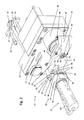
- Fig. 1 is a front perspective view of ammunition depot 1 shown with a rear sliding doors 2, 3, 4 ammunition space.
- the sliding doors 2, 3, 4 are shown in a closed position.
- the ammunition space located behind the sliding doors 2, 3, 4 has three access openings, each of the access openings of each of the sliding doors 2, 3, 4 being closed.
- the access openings are surrounded by a total of an outer frame 5 and separated from each other by bars 6, 7.
- the sliding doors 2, 3, 4 are guided approximately frictionless displaceable along guides 10 arranged in a head region 8 and in a foot region 9 of the sliding doors 2, 3, 4 by means of rollers engaging in the guides 10. It is also possible that sliding elements with the guides 10 allow a displacement of the sliding doors.
- the sliding doors 2, 3, 4 are arranged offset from one another and can be pushed past each other.
- a left sliding door 2 can be pushed into the access opening of a middle sliding door 3.
- the middle sliding door 3 is slidable in the access opening of the left sliding door 2.
- a right sliding door 4 can also be moved into the access opening of the middle sliding door 3.
- Each of the sliding doors 2, 3, 4 has a front-operated emergency locking mechanism 11, which allows a definition of the sliding doors 2, 3, 4 relative to the outer frame 5 and the spars 6, 7.
- the emergency locking mechanisms 11 are arranged in a recess of the sliding doors 2, 3, 4, wherein the operation of the emergency locking mechanisms 11 is made possible by a respective opening in the front of the sliding doors 2, 3, 4.
- respective drive devices 12, 13, 14 are assigned to one of the sliding doors 2, 3, 4, which interact with a respective toothed rack 15, 16, 17 attached to one of the sliding doors 2, 3, 4.
- the racks 15 and 17 are arranged on the outside of the sliding doors 2 and 4, the rack 16 on the inside of the sliding door 3.
- the drive devices 12, 13, 14 each have at least one pinion, with the teeth of the pinions engaging in the complementary tooth rows of the toothed racks.
- the drive devices are fixed relative to the frame 5, so that a rotation of the pinion produces a forward or reverse thrust of the racks in the opening direction A, whereby the firmly connected to the racks sliding doors 2, 3, 4 are opened or closed.
- the sliding doors 2, 3, 4 are releasably connected by screw 18 with the racks 15, 16, 17 releasably.
- the racks 15, 17 of the outer sliding doors 2, 4 are placed on a front side of the sliding doors 2, 4, while the rack 16 of the middle sliding door 3 is disposed on a rear side of the sliding doors.
- Fig. 2 the middle drive device 13 is shown, which has a pinion 19 for connection to the rack 16.
- the pinion 19 is part of a drive train and mounted on one end of a shaft 20.
- the end of the shaft 20 protrudes through a circular opening 21 of a holding plate 22, which by means of a fastening screw 23 at one in the Fig. 2 not shown, connected to the frame 5 is fixedly locked in place.
- the shaft 20 is driven by a belt drive 25 arranged in a housing 24 of the drive device 13.
- the belt drive 25 is in turn operated by a drive shaft 26, which extends after the transmission through a front cover 27 and a drive shaft 26 surrounding the return fuse 28 and finally ends in a complementary to the drive shaft 26 formed opening 29 of a drive plate 31 in an actuator 30.
- the drive plate 31 By a rotation of the actuating device 30, the drive plate 31 is rotated, whereby the drive shaft 26, which is positively connected via the opening 29, is driven with the return safety device 28 unlocked.
- the pinion 19, the shaft 20 and the belt drive 25 form a door-side drive train of the central drive device 13.
- the drive shaft 26 and the actuator 30 form a frame-side drive train, wherein the drive devices 12, 13, 14 do not differ with respect to the frame-side drive train.
- the return fuse 28 is designed such that it completely prevents movement of the drive shaft 26 in a secured state and thus defines the remaining drive components of the door-side drive train, the middle rack 16 and finally the sliding door 3. An unintentional displacement of the sliding door 3 is therefore advantageously reliably prevented.
- the sliding door 3 can be advantageously stopped and fixed in any position.
- the connected to the opening 29 end of the drive shaft 26 is configured such that an additional pneumatically, hydraulically or electrically driven automatic drive (not shown) with the drive shaft 26 is connectable.
- the end face of the drive shaft 26 has a hexagonal recess 41 and a hexagonal outer wall 42, so that a complementary connection member of the automatic drive, the drive shaft 26 can rotate the drive shaft 26 by connecting the connecting member and the end face of the drive shaft 26.
- the front side can also be configured differently, for example with a square internal recess or a threaded hole, in which case the connecting member is designed accordingly.
- actuator 30 comprises a rotatable drive plate 31 with the opening 29.
- the drive plate 31 can be rotated about an axis defined by the drive shaft 26 axis B.
- the drive plate 31 has an unwound by 90 ° relative to a central portion 32 of the drive plate 31 first end portion 33, which is designed as a two-part fork.
- a bore 35 is arranged, in which a hinge pin 34 is rotatably supported.
- a correspondingly formed second bore through which a second hinge pin is guided, is provided in the second prong of the fork.
- the first end portion 33 is pivotally and rotatably connected to the drive plate 31 with a handle 37 by means of pierced articulation webs 38 and link rods in an inner region 39 of the fork 36.
- the handle 37 forms an actuating element of the drive device 12, 13, 14th
- a narrow arm 43 of a parallel to the drive plate 31 extending pressure plate 44 is arranged.
- the narrow boom 43 is fork-shaped, wherein in a interior of the boom 41 between the two forks 45, a ball bearing 46 is arranged.
- a pressure pin 70 is pressed by the actuator 53 against a plate spring 67 of the clutch, via which the blades 68 are biased in the closed state of the multi-plate clutch.
- the plate spring 67 is compressed and thus transferred to the blades 68 in the disconnected state.
- the fitting 71 with the shaft 26 can be freely rotated within the coupling.
- a deadman safety device is created in a simple manner, wherein when the handball safety device 50 is released, a determination of the corresponding drive device 12, 13, 14 takes place. at not actuated handball safety device 50, the clearance of the drive shaft 26 is prevented.
- the handle 37 is pivotally formed so that it can be pivoted into a space-saving rest position, if it is not needed.
- the handle 37 has an unlocking ring 74.
- a non-illustrated in the figures via a spring-biased pin of the handle 37 can be transferred from a detent position within a groove 76 of the drive plate 31 in a release position in which the pin is removed from the groove 76.
- the handle 37 can pivot about a pivot axis formed by the hinge pin 34 in the direction of the drive plate 31.
- a handle 37 of the biased pin presses on a rounded outer surface of a zinc of the fork-like end of the drive plate 31 until it engages in a second groove 76 in the drive plate 31.
- the handle 37 is substantially parallel to the drive plate 31 at this.
- Fig. 4 and Fig. 5 For example, one of the outer drive devices 12, 14 is shown, which also have a housing 24 with a front cover 27.
- the actuator 30 is identical to the actuator of the center drive device 13.
- the inner housing 54 has in a central region a taper 56, wherein in the taper 56, a belt 57 of the gear 55 is movable.
- the taper 56 can be arranged on one of the spars 6, 7, so that the drive device 12, 14 extends on both sides of the spar 6, 7.
- a drive belt 58 is connected, which is connected to a first shaft 59 of the transmission 55th is connected and transmits a rotation on the first shaft 59.
- a belt 57 is connected to the first shaft 59 in a sliding door 2, 4 facing portion of the first shaft 59 with a gear 60.
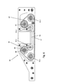
- Fig. 6 the structure of the transmission 55 is shown.
- the belt 57 which may alternatively be a chain, is driven by the gear 60 mounted on the driven first shaft 59.
- the belt 57 is guided by gears 62.1, 62.2 and deflection rollers 61.1, 61.2 and thereby drives a second shaft 63, also through cooperation with a gear 64 of the second shaft 63, to.
- the pulleys 61.1, 61.2 the course of the belt 57 is advantageously limited to the taper 56 of the housing, so that parts of the drive device can be arranged on both sides of the spar.
- a first pinion 65 and on the second shaft 63 a second pinion 66 is mounted, wherein the first pinion 65 on the one hand of the spar 6, 7 and the second pinion 66 on the other hand of the spar 6, 7 is located.
- the teeth of the rack 15, 17 engage in the teeth of the pinion 64, 65, when the sliding door 2, 4 is located on the corresponding side of the spar.
- the first pinion 65 and the second pinion 66 may be simultaneously engaged with the front rack 15, 17, so that a synchronous displacement from one side of the beam 6, 7 to the other side of the spar 6, 7 takes place.
- a clamping set 69 is provided on the pinion 65, in the dissolved position, the pinion 65 and 66 can be rotated independently.
- a clamping set can be arranged on the pinion 66.
- a first section of the belt 57 is the first drive train and a second section of the belt 57 is assigned to the second drive train.
- first pinion 65 and the second pinion 66 in contrast to the pinion 19 of the central drive device on the front of the sliding doors 2, 4 are arranged.
Landscapes
- Engineering & Computer Science (AREA)
- General Engineering & Computer Science (AREA)
- Power-Operated Mechanisms For Wings (AREA)
Abstract
Description
- Die Erfindung betrifft ein verschließbares Munitionsdepot in einem Fahrzeug, insbesondere einem militärischen Fahrzeug, mit einem über eine Schiebetüre verschließbaren Munitionsraum.
- Munitionsdepots in Fahrzeugen sind vorzugsweise gepanzerte Lagerräume für Munitionskörper, beispielsweise Treibladungen, Geschosse oder patronierte Munition. Die Munitionsdepots müssen von den übrigen Fahrzeuginnenräumen durch gepanzerte Türen getrennt sein, so dass bei einer unbeabsichtigten Zündung der Munitionskörper in dem Munitionsraum ein Schutz für die Fahrzeuginsassen hergestellt ist. Dazu können Schiebetüren verwendet werden, die mit einer großen Wandstärke ausgebildet sind, um dem Druck einer Explosion standhalten zu können. Dies bedingt allerdings ein hohes Gewicht der Schiebetüren, so dass eine Bedienung der Schiebetüren von den Insassen des Fahrzeugs einen hohen Kraftaufwand erfordert.
- Aus der Praxis sind Munitionsdepots mit Verschlussvorrichtungen mit wie in
DE 42 00 903 A1 gezeigten Schiebetüren bekannt, wobei die Schiebetüren in einer geschlossenen Endstellung sicher an den Seitenholmen verriegelt werden können. Nachteilig kann bei einer Schräglage des Fahrzeugs ein ungewolltes Verschieben oder ein erschwerte Bedienen der Schiebetüren auftreten. Ferner nachteilig können durch das hohe Gewicht der Schiebetüren bei einer unvorsichtigen manuellen Verschiebung leicht Verletzungen durch ein Zusammenpressen der Hand zwischen der Schiebetür und den Seitenholmen bzw. zwischen zwei Schiebetüren auftreten, was insbesondere durch auftretende Seitenbeschleunigungen wie beispielsweise in Hanglage oder während einer Fahrt über eine unebene Fahrbahn begünstigt werden kann. - Es ist die Aufgabe der Erfindung, ein Munitionsdepot anzugeben, das auch in Schräglage sicher geöffnet und geschlossen werden kann.
- Diese Aufgabe wird durch ein Munitionsdepot mit den Merkmalen des Anspruchs 1 gelöst.
- Ein erfindungsgemäßes Munitionsdepot, insbesondere zur Anordnung an einem militärischen Fahrzeug, weist eine Schiebetür zum Verschließen eines Munitionsraums des Munitionsdepots auf. Dabei ist die Schiebetür durch eine Antriebsvorrichtung zwischen einer Offenstellung und einer Schließstellung bewegbar, wobei die Schiebetür durch eine Rücklaufsicherung gegen unbeabsichtigte Bewegungen gesichert ist. Hierdurch lässt sich die Schiebetür vorteilhaft in jeder beliebigen Stellung zwischen der Offenstellung und der Schließstellung durch die Rücklaufsicherung festlegen. Auch kann hierdurch eine Verletzung des Bedieners der Schiebetür bei einer Schieflage des Munitionsdepots verhindert werden.
- Vorzugsweise weist die Antriebsvorrichtung ein Ritzel auf. Durch eine Wirkverbindung des Ritzels mit einem zu dem Ritzel komplementär ausgebildeten Eingreifelement, beispielsweise einer Zahnstange oder Kette, ist vorteilhaft ein stufenloser Antrieb der Schiebetür geschaffen. Dabei ist in einer bevorzugten Ausführungsform das Eingreifelement an der Schiebetür und das Ritzel an einem die Schiebetür umgebenden Rahmen angeordnet. Alternativ kann das Ritzel an der Schiebetür und das Eingreifelement an dem Rahmen angeordnet sein.
- In einer bevorzugten Ausgestaltung weist die Antriebsvorrichtung einen als Manuellantrieb ausgebildeten Antrieb auf, so dass die Schiebetür vorteilhaft von Hand zwischen der Offenstellung und der Schließstellung bewegt werden kann.
- Vorzugsweise weist die Antriebsvorrichtung einen als Automatikantrieb ausgebildeten Antrieb auf, so dass die Bewegung der Schiebetür automatisch ausgeführt werden kann. Vorteilhaft kann so auch die manuelle Bewegung der Schiebetür unterstützt werden. Der Automatikantrieb wird vorzugsweise als elektrischer, pneumatischer und/oder hydraulischer Antrieb ausgebildet, wobei der elektrische Antrieb vorteilhaft annähernd wartungsfrei betrieben werden kann. Vorzugsweise kann der Automatikantrieb an einer in der Antriebsvorrichtung wirkenden Welle, vorzugsweise einer Antriebswelle, angebunden werden.
- In einer bevorzugten Weiterbildung umfasst die Antriebsvorrichtung eine Zahnstange, wobei die Zahnstange vorteilhaft an der Schiebetür befestigt ist und beispielsweise durch ein Ritzel angetrieben werden kann. Dabei ist die übrige Antriebsvorrichtung vorzugsweise an einem die Schiebetür umgebenden Türrahmen fest angeordnet. Dadurch ist vorteilhaft eine einfache und sichere Antriebsvorrichtung geschaffen.
- Vorzugsweise umfasst die Antriebsvorrichtung eine Kette und/oder einen Riemen, so dass die Wirkverbindung zwischen dem Antrieb und der Schiebetür vorteilhaft nicht linear ausgeführt werden muss und umgelenkt werden kann. In einer weiteren bevorzugten Weiterbildung weist die Antriebsvorrichtung einen Linearantrieb auf.
- Ferner ist in einer weiteren bevorzugten Weiterbildung der Antriebsvorrichtung ein Getriebe zur vorteilhaften Kraftübertragung und -wandlung zwischen dem Antrieb und der Schiebetür vorgesehen. Dadurch kann eine Kraft einleitende Drehbewegung in eine nach Bedarf angepasste translatorische Bewegung der Schiebetür übersetzt werden.
- Vorzugsweise weist die Rücklaufsicherung eine Bremse auf. Durch die Bremse können, insbesondere gegenüber einem Türrahmen bewegbare, Teile der Antriebsvorrichtung oder der Schiebetür abgebremst werden. Dadurch wird vorteilhaft die Bediensicherheit im Umgang mit der Schiebetür und der Antriebsvorrichtung erhöht. Ein Auslöser der Bremse kann vorzugsweise als auf eine Antriebskomponente wirkender Kipphebel oder als federbeaufschlagter Stift ausgebildet sein.
- Vorzugsweise umfasst die Rücklaufsicherung eine Totmannsicherung, die in einer vorteilhaften Weiterbildung eine durch eine Handbetätigung entriegelbare Feststellvorrichtung, insbesondere eine Handballensicherung, aufweist. Hierdurch wird vorteilhaft eine Festlegung der Schiebetür bei einem Loslassen der Totmannsicherung erreicht. Dabei kann die Feststellvorrichtung in einer bevorzugten Weiterbildung die Bremse umfassen und/oder betätigen. So kann beispielsweise bei starken Beschleunigungen des Fahrzeugs und einem daraufhin ungewollten Loslassen der Totmannsicherung eine unkontrollierte Bewegung der Schiebetür verhindert werden.
- In einer bevorzugten Weiterbildung umfasst die Rücklaufsicherung eine Feststellkupplung, insbesondere eine Rutschkupplung, die in einem freigegebenen Zustand der Rücklaufsicherung, in welchem die Schiebetür bewegbar ist, von einem Antriebsstrang der Antriebsvorrichtung entkoppelt ist. In dem freigegebenen Zustand kann der Antriebsstrang frei bewegbar sein. Die Feststellkupplung kann in dem freigegebenen Zustand getrennt und in einem gesicherter Zustand, in welchem die Schiebetür festgelegt ist, geschlossen sein.
- In einer vorteilhaften Weiterbildung ist eine Mehrzahl Schiebetüren mit jeweils einer Antriebsvorrichtung vorgesehen, so dass vorteilhaft das Gewicht der einzelnen Schiebetüren reduziert und damit eine einfache Handhabe verbessert wird.
- In einer bevorzugten Ausgestaltung sind zumindest zwei von Schiebetüren verschließbare Zugangsöffnungen des Munitionsdepots durch einen Holm voneinander getrennt, wodurch vorteilhaft ein stabiler Türrahmen für die Schiebetüren geschaffen ist. Vorzugsweise weisen die Antriebsvorrichtung der Schiebetüren jeweils einen ersten Antriebsstrang und einen zweiten Antriebsstrang auf, wobei in der Offenstellung der Schiebetür der erste Anstriebsstrang einerseits des Holms und der zweite Antriebsstrang andererseits des Holms angeordnet ist. Hierdurch wird vorteilhaft ein Verschieben der Schiebetüren in einen Bereich außerhalb der jeweiligen Zugangsöffnung erreicht, so dass vorteilhaft auch in dem außerhalb gelegenen Bereich eine sichere Verschiebbarkeit erreicht ist.
- In einer bevorzugten Weiterbildung weisen der erste und/oder der zweite Antriebsstrang jeweils ein Ritzel, eine Zahnstange, einen Linearantrieb, einen Riemen, eine Kette und/oder ein Getriebe auf. Hierdurch wird vorteilhaft eine gleichförmige Bewegung der Schiebetür beiderseits des Holmes erreicht. Dadurch, dass der erste Antriebsstrang und/oder der zweite Antriebsstrang zumindest eine gleichartige Antriebskomponente wie das Ritzel, den Linearantrieb, die Zahnstange, den Riemen, eine Kette, und/oder das Getriebe aufweisen, kann ein mit diesen Antriebskomponenten zusammenwirkendes komplementär ausgebildetes Eingreifelement an der Schiebetür entlang der gesamten Bewegungsbahn der Schiebetür eine gleichförmige Verschiebung erzielen.
- In einer bevorzugten Ausführungsform weisen die Schiebetüren jeweils alternierend ein vorderes oder ein hinteres, zu den Antriebskomponenten der Antriebsvorrichtung komplementär ausgebildetes Eingreifelement, insbesondere eine Zahnstange auf, die vorzugsweise mit den Antriebskomponenten der jeweiligen Antriebsvorrichtung der Schiebetüren in einer Wirkverbindung steht. Hierdurch ist vorteilhaft eine einfache und sichere Bewegung der Schiebetür beiderseits eines Holms erreicht.
- In einer bevorzugten Weiterbildung sind mehrere Schiebetüren jeweils mittels einer Rücklaufsicherung gesichert, so dass die Schiebetüren jeweils gegen unbeabsichtigtes Bewegen sicherbar sind. Hierdurch lassen sich insbesondere solche Verletzungen vermeiden, die durch ein Zusammenpressen einer Hand zwischen zwei Schiebetüren herbeigeführt werden können.
- Ferner hat es sich als vorteilhaft erwiesen, wenn Betätigungselemente der Antriebsvorrichtungen jeweils in einem vorderseitig zu den Schiebetüren gelegenen Bereich angeordnet sind, so dass die Schiebetüren von einer Außenseite des Munitionsdepots bedient werden können.
Weitere Merkmale und Ausgestaltungen der Erfindung können den abhängigen Ansprüchen sowie der Beschreibung der in den Zeichnungen gezeigten Ausführungsbeispiele entnommen werden. Darin zeigen: - Fig. 1
- ein Ausführungsbeispiel eines erfindungsgemäßen Munitionsdepots mit einem über Schiebetüren verschließbaren Munitionsraum;
- Fig. 2
- eine erste mittlere Antriebsvorrichtung des in
Fig. 1 gezeigten Munitionsdepot; - Fig. 3
- eine Schnittansicht einer Betätigungsvorrichtung;
- Fig. 4
- eine zweite äußere Antriebsvorrichtung des in
Fig. 1 gezeigten Munitionsdepot; - Fig. 5
- die zweite Antriebsvorrichtung ohne ein Gehäuse eines ersten Antriebsstrangs; und
- Fig. 6
- ein Getriebe der zweiten Antriebsvorrichtung.
- In
Fig. 1 ist eine perspektivische Vorderansicht eines Munitionsdepots 1 mit einem hinter Schiebetüren 2, 3, 4 gelegenen Munitionsraum gezeigt. Die Schiebetüren 2, 3, 4 sind in einer Schließstellung gezeigt. Der hinter den Schiebetüren 2, 3, 4 gelegene Munitionsraum weist drei Zugangsöffnungen auf, wobei jede der Zugangsöffnungen von jeweils einer der Schiebetüren 2, 3 ,4 verschlossen ist. Die Zugangsöffnungen sind insgesamt von einem Außenrahmen 5 umgeben und voneinander durch Holme 6, 7 getrennt. Die Schiebetüren 2, 3, 4 sind entlang von in einem Kopfbereich 8 und in einem Fußbereich 9 der Schiebtüren 2, 3, 4 angeordneten Führungen 10 mittels in die Führungen 10 eingreifende Rollen annähernd reibungsfrei verschiebbar geführt. Es ist auch möglich, dass Gleitelemente mit den Führungen 10 eine Verschiebbarkeit der Schiebetüren ermöglichen. - Die Schiebetüren 2, 3, 4 sind zueinander versetzt angeordnet und lassen sich aneinander vorbei schieben. Dabei kann eine linke Schiebetür 2 in die Zugangsöffnung einer mittleren Schiebetüre 3 geschoben werden. Die mittlere Schiebetüre 3 ist in die Zugangsöffnung der linken Schiebetüre 2 verschiebbar. Schließlich lässt sich eine rechte Schiebetüre 4 ebenfalls in die Zugangsöffnung der mittleren Schiebetüre 3 verschieben.
- Jede der Schiebetüren 2, 3, 4 verfügt über einen von der Vorderseite bedienbaren Notverriegelungsmechanismus 11, der eine Festlegung der Schiebetüren 2, 3, 4 gegenüber dem Außenrahmen 5 bzw. den Holmen 6, 7 ermöglicht. Die Notverriegelungsmechanismen 11 sind in einer Ausnehmung der Schiebetüren 2, 3, 4 angeordnet, wobei die Bedienung der Notverriegelungsmechanismen 11 durch jeweils eine Öffnung in der Vorderseite der Schiebetüren 2, 3 ,4 ermöglicht ist.
- In dem Fußbereich sind jeweils zu einer der Schiebetüren 2, 3, 4 zugeordnete Antriebsvorrichtungen 12, 13, 14 angeordnet, die mit jeweils einer an einer der Schiebetüren 2, 3, 4 befestigten Zahnstange 15, 16, 17 zusammenwirken. Die Zahnstangen 15 und 17 sind an der Außenseite der Schiebetüren 2 und 4, die Zahnstange 16 an der Innenseite der Schiebetür 3 angeordnet. Die Antriebsvorrichtungen 12, 13, 14 weisen jeweils zumindest ein Ritzel auf, wobei die Zähne der Ritzel in die komplementär ausgebildeten Zahnreihen der Zahnstangen eingreifen. Die Antriebsvorrichtungen sind dabei gegenüber dem Rahmen 5 festgelegt, so dass eine Drehung der Ritzel einen Vor- oder Rückschub der Zahnstangen in Öffnungsrichtung A erzeugt, wodurch die mit den Zahnstangen fest verbundenen Schiebetüren 2, 3, 4 geöffnet oder geschlossen werden. Die Schiebetüren 2, 3, 4 sind durch Schraubenverbindungen 18 mit den Zahnstangen 15, 16, 17 lösbar fest verbunden. Die Zahnstangen 15, 17 der äu-βeren Schiebetüren 2, 4 sind an einer Vorderseite der Schiebetüren 2, 4 platziert, während die Zahnstange 16 der mittleren Schiebetüre 3 an einer Rückseite der Schiebetüren angeordnet ist.
- In
Fig. 2 ist die mittlere Antriebsvorrichtung 13 gezeigt, die ein Ritzel 19 zur Verbindung mit der Zahnstange 16 aufweist. Das Ritzel 19 ist Teil eines Antriebsstrangs und an einem Ende einer Welle 20 montiert. Das Ende der Welle 20 ragt dabei durch eine Rundöffnung 21 einer Halteplatte 22, welche mittels einer Befestigungsschraube 23 an einer in derFig. 2 nicht dargestellten, mit dem Rahmen 5 verbundenen Halterung ortsfest arretiert ist. - Die Welle 20 wird von einem in einem Gehäuse 24 der Antriebsvorrichtung 13 angeordneten Riementrieb 25 angetrieben. Der Riementrieb 25 wird seinerseits von einer Antriebswelle 26 betrieben, welche nach dem Getriebe durch eine Frontabdeckung 27 und eine die Antriebswelle 26 umgebende Rücklaufsicherung 28 verläuft und schließlich in einer komplementär zu der Antriebswelle 26 ausgebildeten Öffnung 29 einer Antriebsplatte 31 in einer Betätigungsvorrichtung 30 endet.
- Durch eine Drehung der Betätigungsvorrichtung 30 wird auch die Antriebsplatte 31 gedreht, wodurch die über die Öffnung 29 formschlüssig verbundene Antriebswelle 26 bei entsicherter Rücklaufsicherung 28 angetrieben wird. Das Ritzel 19, die Welle 20 und der Riementrieb 25 bilden einen türseitigen Antriebsstrang der mittleren Antriebsvorrichtung 13. Die Antriebswelle 26 und die Betätigungsvorrichtung 30 bilden einen rahmenseitigen Antriebsstrang, wobei sich die Antriebsvorrichtungen 12, 13, 14 hinsichtlich des rahmenseitigen Antriebsstrangs nicht unterscheiden.
- Die Rücklaufsicherung 28 ist derart ausgebildet, dass sie in einem gesicherten Zustand eine Bewegung der Antriebswelle 26 gänzlich unterbindet und damit die übrigen Antriebskomponenten des türseitigen Antriebsstrangs, die mittlere Zahnstange 16 und schließlich die Schiebetüre 3 festlegt. Ein unbeabsichtigtes Verschieben der Schiebetüre 3 wird daher vorteilhaft sicher verhindert. Darüber hinaus kann die Schiebetüre 3 vorteilhaft in jeder beliebigen Position angehalten und festgelegt werden.
- Das mit der Öffnung 29 verbundene Ende der Antriebswelle 26 ist derart ausgestaltet, dass ein zusätzlicher pneumatisch, hydraulisch oder elektrisch angetriebener Automatikantrieb (nicht gezeigt) mit der Antriebswelle 26 verbindbar ist. Dazu weist die Stirnseite der Antriebswelle 26 eine Sechskantinnenausnehmung 41 und eine Sechskantaussenwandung 42 auf, so dass ein hierzu komplementär ausgebildetes Anbindungsglied des Automatikantriebs die Antriebswelle durch ein Verbinden des Anbindungsglieds und der Stirnseite der Antriebswelle 26 die Antriebswelle 26 rotieren kann. Es versteht sich, dass die Stirnseite auch andersartig ausgestaltet sein kann, beispielsweise mit einer Vierkantinnenausnehmung oder einer Gewindebohrung, wobei dann das Anbindungsglied entsprechend ausgebildet ist.
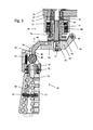
- Die in
Fig. 3 in einer Schnittansicht gezeigte Betätigungsvorrichtung 30 umfasst eine drehbare Antriebsplatte 31 mit der Öffnung 29. Die Antriebsplatte 31 kann um eine durch die Antriebswelle 26 definierte Achse B gedreht werden. Die Antriebsplatte 31 weist einen um 90° gegenüber einem Mittelabschnitt 32 der Antriebsplatte 31 abgewickelten ersten Endabschnitt 33 auf, der als zweigliedrige Gabel ausgestaltet ist. In einem ersten Zinken der Gabel ist eine Bohrung 35 angeordnet, in welcher ein Gelenkbolzen 34 drehbar gehalten ist. Eine entsprechend ausgebildete zweite Bohrung, durch welche ein zweiter Gelenkbolzen geführt ist, ist im zweiten Zinken der Gabel vorgesehen. Der erste Endabschnitt 33 ist mit einem Handgriff 37 mittels durchbohrter Anlenkstege 38 und Gelenkstangen in einem Innenbereich 39 der Gabel 36 gelenkig und drehbar mit der Antriebsplatte 31 verbunden. Der Handgriff 37 bildet dabei ein Betätigungselement der Antriebsvorrichtung 12, 13, 14. - Ferner ist im Bereich zwischen den Anlenkstegen 38 ein schmaler Ausleger 43 einer parallel zu der Antriebsplatte 31 verlaufenden Druckplatte 44 angeordnet. Der schmale Ausleger 43 ist gabelförmig ausgestaltet, wobei in einem Inneren des Auslegers 41 zwischen den beiden Gabelzinken 45 ein Kugellager 46 angeordnet ist.
- Die Druckplatte 44 hat einen zu der Antriebsplatte 31 annähernd parallelen Verlauf, wobei die Druckplatte 44 gegenüber der Antriebsplatte 31 an einem in einem zweiten Endabschnitt 47 der Antriebsplatte 31 drehbar gelagerten Gelenkstift 48 anwickelbar ist, so dass sich eine V-förmige Öffnung zwischen der Druckplatte 44 und der Antriebsplatte 31 ergibt, wenn die Druckplatte 44 in Richtung des Gehäuses 24 um den Gelenkstift 48 gedreht wird. Hierzu weist der Handgriff 37 eine betätigbare, durch ein als Druckfeder ausgebildetes Federelement 49 vorgespannte Handballensicherung 50 auf. Die Handballensicherung 50 ist als quaderförmiger Stab ausgebildet und in einer komplementär hierzu ausgebildeten Ausnehmung des Handgriffs 37 einenends verschwenkbar angelenkt. Dabei weist die Handballensicherung 50 einen nach innen gerichteten Vorsprung 51 auf, der schwimmend an einem das Kugellager 46 beaufschlagenden Bolzenglied 52 des Handgriffs 37 anliegt. Bei einer Betätigung der Handballensicherung 50 wird das Bolzenglied 52 gegen das Kugellager 46 gedrückt und mit dem Kugellager 46 die Druckplatte 44 in Richtung der Rücklaufsicherung 28 verschwenkt. Die bei Betätigung der Handballensicherung 50 initiierten Bewegungsabläufe sind in der
Fig. 3 durch gestrichelte Pfeile angedeutet und sollen im Folgenden näher beschrieben werden: - Beim Verschwenken wirkt die Druckplatte 44 auf ein Stellglied 53 der Rücklaufsicherung 28 derart ein, dass die Rücklaufsicherung 28 in den freigegebenen Zustand übergeht.
- Bei dem Ausführungsbespiel ist die Rücklaufsicherung 28 als Lamellenrutschkupplung ausgebildet, die nach Art einer Festellkupplung verwendet wird. Die Lamellenrutschkupplung weist ein mit der Welle 26 drehbares Formstück 71 auf. In dem geschlossenen Zustand der Kupplung ist das Formstück 71 über Lamellen 68 kraftschlüssig mit einem Außenflansch 72 der Kupplung verbunden. Der Außenflansch 72 ist über eine Schraube 73 an der Frontabdeckung 27 des Gehäuses 14 festgelegt. In dem geschlossenen Zustand ist eine Drehbewegung der Welle 26 nicht möglich, die Rücklaufsicherung befindet sich in ihrer sichernden Stellung.
- Zum Freigeben der Drehbewegung der Welle 26 wird ein Druckstift 70 durch das Stellglied 53 gegen eine Tellerfeder 67 der Kupplung gedrückt, über welche die Lamellen 68 in dem geschlossenen Zustand der Lamellenrutschkupplung vorgespannt sind. Durch den Druck des Druckstiftes 70 wird die Tellerfeder 67 zusammengedrückt und somit die Lamellen 68 in den getrennten Zustand überführt. Im getrennten Zustand kann das Formstück 71 mit der Welle 26 frei innerhalb der Kupplung gedreht werden.
- Durch die Handballensicherung 50 ist auf einfache Weise eine Totmannsicherung geschaffen, wobei bei einem Loslassen der Handballensicherung 50 eine Feststellung der entsprechenden Antriebsvorrichtung 12, 13, 14 erfolgt. Bei nicht betätigter Handballensicherung 50 wird der Freigang der Antriebswelle 26 unterbunden.
- Wie der
Fig. 2 undFig. 3 weiter zu entnehmen, ist der Handgriff 37 schwenkbar ausgebildet, so dass er in eine platzsparende Ruhestellung geschwenkt werden kann, sofern er nicht benötigt wird. Hierzu weist der Handgriff 37 einen Entriegelungsring 74 auf. Durch Zug an dem Entriegelungsring 74 kann ein in den Figuren nicht dargestellter über eine Feder vorgespannter Stift des Handgriffs 37 aus einer Rastposition innerhalb einer Nut 76 der Antriebsplatte 31 in eine Freigabeposition überführt werden, in welcher der Stift aus der Nut 76 entfernt ist. In der Freigabeposition lässt sich der Handgriff 37 um eine durch die Gelenkbolzen 34 gebildete Schwenkachse in Richtung der Antriebsplatte 31 verschwenken. Beim Verschwenken des Handgriffs 37 drückt der vorgespannte Stift auf eine abgerundete Außenfläche eines Zinkes des gabelartigen Endes der Antriebsplatte 31 bis er in einer zweiten Nut 76 in der Antriebsplatte 31 einrastet. In dieser Ruhestellung liegt der Handgriff 37 im Wesentlichen parallel zu der Antriebsplatte 31 an dieser an.
InFig. 4 undFig. 5 ist eine der äußeren Antriebsvorrichtungen 12, 14 gezeigt, welche ebenfalls ein Gehäuse 24 mit einer Frontabdeckung 27 aufweisen. Die Betätigungsvorrichtung 30 ist identisch zu der Betätigungsvorrichtung der mittleren Antriebsvorrichtung 13. - An das Gehäuse 24 ist ein Innengehäuse 54 mit einem darin vorgesehenen und in
Fig. 5 gezeigten Getriebe 55 angeordnet. Das Innengehäuse 54 weist in einem mittleren Bereich eine Verjüngung 56 auf, wobei in der Verjüngung 56 ein Riemen 57 des Getriebes 55 beweglich verläuft. Die Verjüngung 56 kann an einen der Holme 6, 7 angeordnet werden, so dass die Antriebsvorrichtung 12, 14 beiderseits des Holms 6, 7 verläuft. An die Antriebswelle 26 ist ein Antriebsriemen 58 angebunden, der mit einer ersten Welle 59 des Getriebes 55 verbunden ist und eine Rotation auf die erste Welle 59 überträgt. Ein Riemen 57 ist mit der ersten Welle 59 in einem der Schiebetüre 2, 4 zugewandten Abschnitt der ersten Welle 59 mit einem Zahnrad 60 verbunden. - In
Fig. 6 ist der Aufbau des Getriebes 55 dargestellt. Der Riemen 57, der alternativ auch eine Kette sein kann, wird von dem auf der angetriebenen ersten Welle 59 montierten Zahnrad 60 vorangetrieben. Der Riemen 57 wird von Zahnrädern 62.1, 62.2 und Umlenkrollen 61.1, 61.2 geführt und treibt dabei eine zweite Welle 63, ebenfalls durch ein Zusammenwirken mit einem Zahnrad 64 der zweiten Welle 63, an. Durch die Umlenkrollen 61.1, 61.2 wird der Verlauf des Riemens 57 vorteilhaft auf die Verjüngung 56 des Gehäuses begrenzt, so dass Teile der Antriebsvorrichtung beiderseits des Holms anordbar sind. - Auf der ersten angetriebenen Welle 59 ist dabei ein erstes Ritzel 65 und auf der zweiten Welle 63 ein zweites Ritzel 66 montiert, wobei sich das erste Ritzel 65 einerseits des Holms 6, 7 und das zweite Ritzel 66 andererseits des Holms 6, 7 befindet. Die Zähne der Zahnstange 15, 17 greifen in die Zähne der Ritzel 64, 65 ein, wenn sich die Schiebetüre 2, 4 auf der entsprechenden Seite des Holms befindet. In einer Position zwischen der Offenstellung und der Schließstellung können das erste Ritzel 65 und das zweite Ritzel 66 gleichzeitig mit der vorderen Zahnstange 15, 17 in Eingriff sein, so dass eine synchrone Verschiebung von einer Seite des Holms 6, 7 auf die andere Seite des Holmes 6, 7 erfolgt. Zur Synchronisation der Ritzel 65 und 66 bei der Montage ist an dem Ritzel 65 ein Spannsatz 69 vorgesehen, in dessen gelöster Stellung die Ritzel 65 und 66 unabhängig voneinander gedreht werden können. Alternativ kann an dem Ritzel 66 ein Spannsatz angeordnet sein.
- Die einerseits des Holms 6, 7 angeordneten Antriebselemente, umfassend das erste Ritzel 65, die erste Welle 59 sowie die Umlenkrolle 61.1 und das Zahnrad 62.2, bilden einen ersten Antriebsstrang der Antriebsvorrichtung 12, 14. Die auf der anderen Seite des Holms 6, 7 angeordneten Antriebselemente, umfassend das zweite Ritzel 66, die zweite Welle 63 sowie die Umlenkrolle 61.2 und das Zahnrad 62.2, bilden einen zweiten Antriebsstrang der Antriebsvorrichtung. Ein erster Abschnitt des Riemens 57 ist dabei dem ersten Antriebsstrang und ein zweiter Abschnitt des Riemens 57 ist dabei dem zweiten Antriebsstrang zuzuordnen.
- Es versteht sich, dass das erste Ritzel 65 und das zweite Ritzel 66 im Gegensatz zu dem Ritzel 19 der mittleren Antriebsvorrichtung auf der Vorderseite der Schiebetüren 2, 4 angeordnet sind.
- Mittels der Rücklaufsicherung wird eine Fixierung oder Bremsung der Schiebetür im nichtbetätigten Zustand der Antriebsvorrichtung erreicht. Bei starken Beschleunigungen des Fahrzeugs können somit unkontrollierte Bewegung der Schiebetür verhindert werden.
-
- A
- Öffnungsrichtungen der Schiebetüren
- B
- Drehachsen der Antriebswellen
- 1
- Munitionsdepot
- 2
- linke Schiebetür
- 3
- mittlere Schiebetür
- 4
- rechte Schiebetür
- 5
- Rahmen
- 6
- linker Holm
- 7
- rechter Holm
- 8
- oberer Bereich der Schiebetüren
- 9
- unterer Bereich der Schiebetüren
- 10
- Führung
- 11
- Notverriegelungsmechanismus
- 12
- linke Antriebsvorrichtung
- 13
- mittlere Antriebsvorrichtung
- 14
- rechte Antriebsvorrichtung
- 15
- linke vordere Zahnstange
- 16
- mittlere hintere Zahnstange
- 17
- rechte vordere Zahnstange
- 18
- Schraubenverbindungen
- 19
- Ritzel
- 20
- Welle
- 21
- Rundöffnung
- 22
- Halteplatte
- 23
- Befestigungsbolzen
- 24
- Gehäuse
- 25
- Riementrieb
- 26
- Antriebswelle
- 27
- Frontabdeckung
- 28
- Rücklaufsicherung
- 29
- Öffnung
- 30
- Betätigungsvorrichtung
- 31
- Antriebsplatte
- 32
- Mittelabschnitt der Antriebsplatte
- 33
- erster Endabschnitt der Antriebsplatte
- 34
- Gelenkbolzen
- 35
- Bohrung
- 36
- Gabel
- 37
- Handgriff
- 38
- Anlenkstege
- 39
- Innenbereich der Gabel
- 40
- Ausnehmung
- 41
- Sechskantinnenausnehmung
- 42
- Sechskantaussenwandung
- 43
- schmaler Ausleger
- 44
- Druckplatte
- 45
- Gabelzinken
- 46
- Kugellager
- 47
- zweiter Endabschnitt der Antriebsplatte
- 48
- Gelenkstift
- 49
- Federelement
- 50
- Handballensicherung
- 51
- Vorsprung
- 52
- Bolzenglied
- 53
- Stellglied
- 54
- Innengehäuse
- 55
- Getriebe
- 56
- Verjüngung
- 57
- Kette oder Riemen
- 58
- Riemen
- 59
- erste Welle des Getriebes
- 60
- Zahnrad der ersten Welle
- 61.1-61.2
- Umlenkrolle
- 62.1-61.2
- Zahnrad
- 63
- zweite Welle des Getriebes
- 64
- Zahnrad der zweiten Welle
- 65
- erstes Ritzel
- 66
- zweites Ritzel
- 67
- Kupplungsfeder
- 68
- Lamellen
- 69
- Spannsatz
- 70
- Druckstift
- 71
- Formstück
- 72
- Außenflansch
- 73
- Schraube
- 74
- Entriegelungsring
- 75
- Nut
- 76
- Nut
Claims (15)
- Munitionsdepot, insbesondere zur Anordnung an einem militärischen Fahrzeug, mit einem über eine Schiebetür (2, 3, 4) verschließbaren Munitionsraum, dadurch gekennzeichnet, dass die Schiebetür (2, 3, 4) durch eine Antriebsvorrichtung (12, 13, 14) zwischen einer Offenstellung und einer Schließstellung bewegbar ist, wobei die Schiebetür (2, 3, 4) durch eine Rücklaufsicherung (28) gegen unbeabsichtigte Bewegungen gesichert ist.
- Munitionsdepot nach Anspruch 1, dadurch gekennzeichnet, dass die Antriebsvorrichtung (12, 13, 14) ein Ritzel aufweist.
- Munitionsdepot nach Anspruch 1 oder 2, dadurch gekennzeichnet, dass die Antriebsvorrichtung (12, 13, 14) als ein Betätigungselement einen Manuellantrieb (30), insbesondere einen Kurbelantrieb, aufweist.
- Munitionsdepot nach einem der vorhergehenden Ansprüche, dadurch gekennzeichnet, dass die Antriebsvorrichtung (12, 13, 14) als ein Betätigungselement einen Automatikantrieb, insbesondere einen elektrischen, pneumatischen, und/oder hydraulischen Antrieb, aufweist.
- Munitionsdepot nach einem der vorhergehenden Ansprüche, dadurch gekennzeichnet, dass die Antriebsvorrichtung (12, 13, 14) eine Zahnstange (15, 16, 17), einen Riemen (25, 57, 58), einen Linearantrieb, eine Kette und/oder ein Getriebe (55) umfasst.
- Munitionsdepot nach einem der vorhergehenden Ansprüche, dadurch gekennzeichnet, dass die Rücklaufsicherung (28) eine Bremse aufweist.
- Munitionsdepot nach einem der vorhergehenden Ansprüche, dadurch gekennzeichnet, dass die Rücklaufsicherung (28) eine Totmannsicherung, insbesondere eine durch eine Handbetätigung entriegelbare Feststellvorrichtung, umfasst.
- Munitionsdepot nach einem der vorhergehenden Ansprüche, dadurch gekennzeichnet, dass die Rücklaufsicherung (28) eine Feststellkupplung umfasst, die in einem freigegebenen Zustand der Rücklaufsicherung (28), in welchem die Schiebetür (2, 3, 4) bewegbar ist, von einem Antriebsstrang der Antriebsvorrichtung (12, 13, 14) entkoppelt ist.
- Munitionsdepot nach einem der vorhergehenden Ansprüche, gekennzeichnet durch eine Mehrzahl Schiebetüren (2, 3, 4), die jeweils von einer Antriebsvorrichtung (12, 13, 14) bewegbar sind.
- Munitionsdepot nach Anspruch 9, dadurch gekennzeichnet, dass zwei von Schiebetüren (2, 3, 4) verschließbare Zugangsöffnungen des Munitionsdepots durch einen Holm (6, 7) voneinander getrennt sind.
- Munitionsdepot nach Anspruch 10, dadurch gekennzeichnet, dass die Antriebsvorrichtungen (2, 4) einen ersten Antriebsstrang und einen zweiten Antriebsstrang aufweisen und dass der erste Antriebsstrang einerseits des Holms (6, 7) und der zweite Antriebsstrang andererseits des Holms angeordnet ist.
- Munitionsdepot nach Anspruch 11, dadurch gekennzeichnet, dass der erste Antriebsstrang und/oder der zweite Antriebsstrang mit einem an der Schiebetür festgelegten Eingreifelement, insbesondere einer Zahnstange (15, 17), zusammenwirken.
- Munitionsdepot nach Anspruch 11 oder 12, dadurch gekennzeichnet, dass der erste Antriebsstrang und/oder der zweite Antriebsstrang jeweils ein Ritzel (65, 66), einen Riemen (57, 58), einen Linearantrieb und/oder ein Getriebe (55) umfasst.
- Munitionsdepot nach einem der Ansprüche 9 bis 13, dadurch gekennzeichnet, dass jeweils ein Eingreifelement, insbesondere eine Zahnstange (15, 16, 17), an den Schiebetüren (2, 3, 4) alternierend auf einer Vorderseite oder einer Rückseite angeordnet ist, wobei die Zahnstangen (15, 16, 17) zur Verschiebung der Schiebetüren eine Wirkverbindung mit den jeweiligen Antriebsvorrichtungen (12, 13, 14) aufweisen.
- Munitionsdepot nach Anspruch 14, dadurch gekennzeichnet, dass Betätigungselemente (30, 37) der Antriebsvorrichtungen (12, 13, 14) jeweils in einem vorderseitig zu den Schiebetüren (2, 3, 4) gelegenen Bereich angeordnet sind.
Applications Claiming Priority (1)
| Application Number | Priority Date | Filing Date | Title |
|---|---|---|---|
| DE102011056513A DE102011056513A1 (de) | 2011-12-16 | 2011-12-16 | Munitionsdepot |
Publications (3)
| Publication Number | Publication Date |
|---|---|
| EP2604968A2 true EP2604968A2 (de) | 2013-06-19 |
| EP2604968A3 EP2604968A3 (de) | 2015-01-07 |
| EP2604968B1 EP2604968B1 (de) | 2016-03-16 |
Family
ID=47504682
Family Applications (1)
| Application Number | Title | Priority Date | Filing Date |
|---|---|---|---|
| EP12196814.3A Active EP2604968B1 (de) | 2011-12-16 | 2012-12-12 | Schiebetürvorrichtung für Munitionsmagazin |
Country Status (3)
| Country | Link |
|---|---|
| EP (1) | EP2604968B1 (de) |
| DE (1) | DE102011056513A1 (de) |
| ES (1) | ES2581755T3 (de) |
Cited By (2)
| Publication number | Priority date | Publication date | Assignee | Title |
|---|---|---|---|---|
| US20160051032A1 (en) * | 2013-03-29 | 2016-02-25 | L'oreal | Device for packaging and applying a cosmetic product |
| CN115752099A (zh) * | 2022-11-03 | 2023-03-07 | 昆明理工大学 | 一种rm机器人补给装置 |
Families Citing this family (1)
| Publication number | Priority date | Publication date | Assignee | Title |
|---|---|---|---|---|
| DE102023133598A1 (de) * | 2023-11-30 | 2025-06-05 | Rheinmetall Landsysteme Gmbh | Schiebetürmodul, turm und fahrzeug |
Citations (1)
| Publication number | Priority date | Publication date | Assignee | Title |
|---|---|---|---|---|
| DE4200903A1 (de) | 1992-01-16 | 1993-07-22 | Wegmann & Co Gmbh | Munitionsbunker an einem kampfpanzerturm |
Family Cites Families (14)
| Publication number | Priority date | Publication date | Assignee | Title |
|---|---|---|---|---|
| DE955292C (de) * | 1953-07-26 | 1957-01-03 | Friedrich Wilhelm Kiekert | Sicherheitseinrichtung fuer Tueren, insbesondere Fahrzeugtueren, die durch einen Kraftantrieb geschlossen werden |
| DE2552470C1 (de) | 1975-11-22 | 1989-03-02 | Wegmann & Co | Munitionsbunker,insbesondere an Kampfpanzertuermen |
| AT384590B (de) | 1985-02-22 | 1987-12-10 | Stabeg Apparatebau Gmbh | Betaetigungsvorrichtung fuer fahrzeugschiebetueren |
| AT397409B (de) * | 1988-09-30 | 1994-04-25 | Swoboda Karosserie Stahlbau | Antriebsanordnung für eine türe mit mehreren türsegmenten |
| DE9010182U1 (de) | 1990-07-05 | 1990-09-06 | Dowaldwerke Adolph Dowald GmbH & Co KG, 2800 Bremen | Vorrichtung zum selbsttätigen Schließen von Türen |
| CH687771A5 (de) | 1994-06-27 | 1997-02-14 | Pamag Ag | Bodenbearbeitungsgeraet mit Totmannsicherung. |
| GB2323124B (en) | 1997-03-11 | 2000-12-06 | Delphi Automotive Systems Gmbh | Electrically operated slidable door actuator |
| DE19910642A1 (de) | 1999-03-10 | 2000-09-21 | Metzeler Automotive Profiles | Einklemmschutz für handbetätigtes Schließteil |
| AT500462B1 (de) | 2004-04-23 | 2010-02-15 | Knorr Bremse Gmbh | Schiebetür bzw. schwenkschiebetür |
| DE102004063737A1 (de) | 2004-12-29 | 2006-07-13 | Brose Fahrzeugteile Gmbh & Co. Kommanditgesellschaft, Coburg | Öffnungs- und Schließsystem für eine Kraftfahrzeug-Schiebetür |
| DE102005019150A1 (de) * | 2005-04-25 | 2006-11-02 | Siemens Ag | Verfahren zum Betrieb einer Steuerungseinrichtung für eine Tür und Steuerungseinrichtung hierzu |
| DE102007041360B4 (de) | 2006-12-21 | 2013-05-08 | Dorma Gmbh + Co. Kg | Nachrüstsatz für eine Schiebetür und Schiebetüranlage |
| DE102007032474A1 (de) | 2007-07-10 | 2009-01-29 | Dorma Gmbh + Co. Kg | Schiebetüraufhängung mit integriertem Linearantrieb |
| DE102009032616B4 (de) * | 2008-12-10 | 2024-10-02 | Hettich-Heinze Gmbh & Co. Kg | Antriebsvorrichtung zum motorischen Bewegen einer Schiebetür und Verfahren zum Ansteuern der Antriebsvorrichtung |
-
2011
- 2011-12-16 DE DE102011056513A patent/DE102011056513A1/de not_active Withdrawn
-
2012
- 2012-12-12 EP EP12196814.3A patent/EP2604968B1/de active Active
- 2012-12-12 ES ES12196814.3T patent/ES2581755T3/es active Active
Patent Citations (1)
| Publication number | Priority date | Publication date | Assignee | Title |
|---|---|---|---|---|
| DE4200903A1 (de) | 1992-01-16 | 1993-07-22 | Wegmann & Co Gmbh | Munitionsbunker an einem kampfpanzerturm |
Cited By (4)
| Publication number | Priority date | Publication date | Assignee | Title |
|---|---|---|---|---|
| US20160051032A1 (en) * | 2013-03-29 | 2016-02-25 | L'oreal | Device for packaging and applying a cosmetic product |
| US9955771B2 (en) * | 2013-03-29 | 2018-05-01 | L'oreal | Device for packaging and applying a cosmetic product |
| CN115752099A (zh) * | 2022-11-03 | 2023-03-07 | 昆明理工大学 | 一种rm机器人补给装置 |
| CN115752099B (zh) * | 2022-11-03 | 2024-06-07 | 昆明理工大学 | 一种rm机器人补给装置 |
Also Published As
| Publication number | Publication date |
|---|---|
| DE102011056513A1 (de) | 2013-06-20 |
| EP2604968B1 (de) | 2016-03-16 |
| ES2581755T3 (es) | 2016-09-07 |
| EP2604968A3 (de) | 2015-01-07 |
Similar Documents
| Publication | Publication Date | Title |
|---|---|---|
| EP2859165B1 (de) | Kupplungsvorrichtung zur lösbaren verbindung eines schwenkbeweglich gelagerten karosserieteils, wie fahrzeugtüre, heck- oder frontklappe mit einem fahrzeugstrukturteil einer fahrzeugkarosserie | |
| EP2916045A1 (de) | Parksperrenanordnung und Kraftfahrzeuggetriebe | |
| EP2573300B1 (de) | Kraftfahrzeugtürverschluss | |
| DE112021000048B4 (de) | Elektrisches Schloss für eine Fahrzeugtür | |
| DE102014111426A1 (de) | Anhängekupplung | |
| EP2573301A2 (de) | Heckschloss für ein Kraftfahrzeug | |
| EP2604968B1 (de) | Schiebetürvorrichtung für Munitionsmagazin | |
| EP0320008B1 (de) | Elektromotorisch angetriebenes Türschloss | |
| DE2646158C2 (de) | Schnell lösbare Federkraft-Speichervorrichtung, insbesondere für Feststellbremsen von Kraftfahrzeugen | |
| EP2317037A2 (de) | Schwenkhebelverschluss mit geteilter Betätigungswelle | |
| DE2846550A1 (de) | Verschluss fuer eine kraftfahrzeugtuer | |
| DE1531344C3 (de) | Vorrichtung zum Ziehen und/oder Heben eines Seiles | |
| DE10042191A1 (de) | Kraftfahrzeug-Türschloß mit gesteuertem Stellelement | |
| EP2410113B1 (de) | Minenschutzverriegelung und Verfahren zur Entriegelung einer Minenschutzverriegelung | |
| WO2023138808A1 (de) | Gepanzertes fahrzeug mit notausstiegsluke | |
| DE202007014548U1 (de) | Mitnehmerschlitten für eine Torantriebsvorrichtung, eine solche Torantriebsvorrichtung und ein Tor | |
| AT413043B (de) | Zylinderbetätigbares mehrriegelschloss | |
| DE10318707B4 (de) | Sicherheitseinrichtung | |
| EP3517715B1 (de) | Zuhaltung mit hilfsentriegelung | |
| EP3332208B1 (de) | Fernbedienbare waffenkupplung | |
| AT527847B1 (de) | Staufach | |
| WO2020125858A1 (de) | Schloss für ein kraftfahrzeug | |
| EP1806468B1 (de) | Elektromechanisches Türschloss | |
| EP3299559B1 (de) | Verriegelungordnung für ein fenster | |
| EP1150090A2 (de) | Vorrichtung zum Öffnen und Schliessen des Lukendeckels einer Schiebeluke an einem Kampffahrzeug, insbesondere einem Kampfpanzer |
Legal Events
| Date | Code | Title | Description |
|---|---|---|---|
| PUAI | Public reference made under article 153(3) epc to a published international application that has entered the european phase |
Free format text: ORIGINAL CODE: 0009012 |
|
| AK | Designated contracting states |
Kind code of ref document: A2 Designated state(s): AL AT BE BG CH CY CZ DE DK EE ES FI FR GB GR HR HU IE IS IT LI LT LU LV MC MK MT NL NO PL PT RO RS SE SI SK SM TR |
|
| AX | Request for extension of the european patent |
Extension state: BA ME |
|
| PUAL | Search report despatched |
Free format text: ORIGINAL CODE: 0009013 |
|
| AK | Designated contracting states |
Kind code of ref document: A3 Designated state(s): AL AT BE BG CH CY CZ DE DK EE ES FI FR GB GR HR HU IE IS IT LI LT LU LV MC MK MT NL NO PL PT RO RS SE SI SK SM TR |
|
| AX | Request for extension of the european patent |
Extension state: BA ME |
|
| RIC1 | Information provided on ipc code assigned before grant |
Ipc: F42B 39/28 20060101ALI20141202BHEP Ipc: F41A 9/82 20060101ALN20141202BHEP Ipc: F41A 9/64 20060101ALN20141202BHEP Ipc: F41H 5/22 20060101AFI20141202BHEP |
|
| 17P | Request for examination filed |
Effective date: 20150423 |
|
| RBV | Designated contracting states (corrected) |
Designated state(s): AL AT BE BG CH CY CZ DE DK EE ES FI FR GB GR HR HU IE IS IT LI LT LU LV MC MK MT NL NO PL PT RO RS SE SI SK SM TR |
|
| GRAP | Despatch of communication of intention to grant a patent |
Free format text: ORIGINAL CODE: EPIDOSNIGR1 |
|
| RIC1 | Information provided on ipc code assigned before grant |
Ipc: F41A 9/64 20060101ALN20150817BHEP Ipc: F41A 9/82 20060101ALN20150817BHEP Ipc: F42B 39/28 20060101ALI20150817BHEP Ipc: F41H 5/22 20060101AFI20150817BHEP |
|
| RIC1 | Information provided on ipc code assigned before grant |
Ipc: F41H 5/22 20060101AFI20150909BHEP Ipc: F42B 39/28 20060101ALI20150909BHEP Ipc: F41A 9/64 20060101ALN20150909BHEP Ipc: F41A 9/82 20060101ALN20150909BHEP |
|
| INTG | Intention to grant announced |
Effective date: 20150922 |
|
| RIC1 | Information provided on ipc code assigned before grant |
Ipc: F42B 39/28 20060101ALI20150914BHEP Ipc: F41A 9/82 20060101ALN20150914BHEP Ipc: F41A 9/64 20060101ALN20150914BHEP Ipc: F41H 5/22 20060101AFI20150914BHEP |
|
| GRAS | Grant fee paid |
Free format text: ORIGINAL CODE: EPIDOSNIGR3 |
|
| GRAA | (expected) grant |
Free format text: ORIGINAL CODE: 0009210 |
|
| AK | Designated contracting states |
Kind code of ref document: B1 Designated state(s): AL AT BE BG CH CY CZ DE DK EE ES FI FR GB GR HR HU IE IS IT LI LT LU LV MC MK MT NL NO PL PT RO RS SE SI SK SM TR |
|
| REG | Reference to a national code |
Ref country code: GB Ref legal event code: FG4D Free format text: NOT ENGLISH |
|
| REG | Reference to a national code |
Ref country code: CH Ref legal event code: EP |
|
| REG | Reference to a national code |
Ref country code: IE Ref legal event code: FG4D Free format text: LANGUAGE OF EP DOCUMENT: GERMAN |
|
| REG | Reference to a national code |
Ref country code: AT Ref legal event code: REF Ref document number: 781607 Country of ref document: AT Kind code of ref document: T Effective date: 20160415 |
|
| REG | Reference to a national code |
Ref country code: DE Ref legal event code: R096 Ref document number: 502012006281 Country of ref document: DE |
|
| REG | Reference to a national code |
Ref country code: SE Ref legal event code: TRGR |
|
| REG | Reference to a national code |
Ref country code: NL Ref legal event code: MP Effective date: 20160316 |
|
| REG | Reference to a national code |
Ref country code: LT Ref legal event code: MG4D |
|
| PG25 | Lapsed in a contracting state [announced via postgrant information from national office to epo] |
Ref country code: FI Free format text: LAPSE BECAUSE OF FAILURE TO SUBMIT A TRANSLATION OF THE DESCRIPTION OR TO PAY THE FEE WITHIN THE PRESCRIBED TIME-LIMIT Effective date: 20160316 Ref country code: HR Free format text: LAPSE BECAUSE OF FAILURE TO SUBMIT A TRANSLATION OF THE DESCRIPTION OR TO PAY THE FEE WITHIN THE PRESCRIBED TIME-LIMIT Effective date: 20160316 Ref country code: GR Free format text: LAPSE BECAUSE OF FAILURE TO SUBMIT A TRANSLATION OF THE DESCRIPTION OR TO PAY THE FEE WITHIN THE PRESCRIBED TIME-LIMIT Effective date: 20160617 Ref country code: NO Free format text: LAPSE BECAUSE OF FAILURE TO SUBMIT A TRANSLATION OF THE DESCRIPTION OR TO PAY THE FEE WITHIN THE PRESCRIBED TIME-LIMIT Effective date: 20160616 |
|
| PG25 | Lapsed in a contracting state [announced via postgrant information from national office to epo] |
Ref country code: NL Free format text: LAPSE BECAUSE OF FAILURE TO SUBMIT A TRANSLATION OF THE DESCRIPTION OR TO PAY THE FEE WITHIN THE PRESCRIBED TIME-LIMIT Effective date: 20160316 Ref country code: RS Free format text: LAPSE BECAUSE OF FAILURE TO SUBMIT A TRANSLATION OF THE DESCRIPTION OR TO PAY THE FEE WITHIN THE PRESCRIBED TIME-LIMIT Effective date: 20160316 Ref country code: LT Free format text: LAPSE BECAUSE OF FAILURE TO SUBMIT A TRANSLATION OF THE DESCRIPTION OR TO PAY THE FEE WITHIN THE PRESCRIBED TIME-LIMIT Effective date: 20160316 Ref country code: LV Free format text: LAPSE BECAUSE OF FAILURE TO SUBMIT A TRANSLATION OF THE DESCRIPTION OR TO PAY THE FEE WITHIN THE PRESCRIBED TIME-LIMIT Effective date: 20160316 |
|
| REG | Reference to a national code |
Ref country code: ES Ref legal event code: FG2A Ref document number: 2581755 Country of ref document: ES Kind code of ref document: T3 Effective date: 20160907 |
|
| PG25 | Lapsed in a contracting state [announced via postgrant information from national office to epo] |
Ref country code: IS Free format text: LAPSE BECAUSE OF FAILURE TO SUBMIT A TRANSLATION OF THE DESCRIPTION OR TO PAY THE FEE WITHIN THE PRESCRIBED TIME-LIMIT Effective date: 20160716 Ref country code: EE Free format text: LAPSE BECAUSE OF FAILURE TO SUBMIT A TRANSLATION OF THE DESCRIPTION OR TO PAY THE FEE WITHIN THE PRESCRIBED TIME-LIMIT Effective date: 20160316 Ref country code: PL Free format text: LAPSE BECAUSE OF FAILURE TO SUBMIT A TRANSLATION OF THE DESCRIPTION OR TO PAY THE FEE WITHIN THE PRESCRIBED TIME-LIMIT Effective date: 20160316 |
|
| REG | Reference to a national code |
Ref country code: DE Ref legal event code: R026 Ref document number: 502012006281 Country of ref document: DE |
|
| PLBI | Opposition filed |
Free format text: ORIGINAL CODE: 0009260 |
|
| PG25 | Lapsed in a contracting state [announced via postgrant information from national office to epo] |
Ref country code: SK Free format text: LAPSE BECAUSE OF FAILURE TO SUBMIT A TRANSLATION OF THE DESCRIPTION OR TO PAY THE FEE WITHIN THE PRESCRIBED TIME-LIMIT Effective date: 20160316 Ref country code: PT Free format text: LAPSE BECAUSE OF FAILURE TO SUBMIT A TRANSLATION OF THE DESCRIPTION OR TO PAY THE FEE WITHIN THE PRESCRIBED TIME-LIMIT Effective date: 20160718 Ref country code: CZ Free format text: LAPSE BECAUSE OF FAILURE TO SUBMIT A TRANSLATION OF THE DESCRIPTION OR TO PAY THE FEE WITHIN THE PRESCRIBED TIME-LIMIT Effective date: 20160316 Ref country code: RO Free format text: LAPSE BECAUSE OF FAILURE TO SUBMIT A TRANSLATION OF THE DESCRIPTION OR TO PAY THE FEE WITHIN THE PRESCRIBED TIME-LIMIT Effective date: 20160316 Ref country code: SM Free format text: LAPSE BECAUSE OF FAILURE TO SUBMIT A TRANSLATION OF THE DESCRIPTION OR TO PAY THE FEE WITHIN THE PRESCRIBED TIME-LIMIT Effective date: 20160316 |
|
| 26 | Opposition filed |
Opponent name: RHEINMETALL LANDSYSTEME GMBH Effective date: 20161104 |
|
| REG | Reference to a national code |
Ref country code: FR Ref legal event code: PLFP Year of fee payment: 5 |
|
| PLAB | Opposition data, opponent's data or that of the opponent's representative modified |
Free format text: ORIGINAL CODE: 0009299OPPO |
|
| PLAX | Notice of opposition and request to file observation + time limit sent |
Free format text: ORIGINAL CODE: EPIDOSNOBS2 |
|
| PG25 | Lapsed in a contracting state [announced via postgrant information from national office to epo] |
Ref country code: DK Free format text: LAPSE BECAUSE OF FAILURE TO SUBMIT A TRANSLATION OF THE DESCRIPTION OR TO PAY THE FEE WITHIN THE PRESCRIBED TIME-LIMIT Effective date: 20160316 |
|
| R26 | Opposition filed (corrected) |
Opponent name: RHEINMETALL LANDSYSTEME GMBH Effective date: 20161104 |
|
| PG25 | Lapsed in a contracting state [announced via postgrant information from national office to epo] |
Ref country code: BG Free format text: LAPSE BECAUSE OF FAILURE TO SUBMIT A TRANSLATION OF THE DESCRIPTION OR TO PAY THE FEE WITHIN THE PRESCRIBED TIME-LIMIT Effective date: 20160616 |
|
| PG25 | Lapsed in a contracting state [announced via postgrant information from national office to epo] |
Ref country code: BE Free format text: LAPSE BECAUSE OF NON-PAYMENT OF DUE FEES Effective date: 20161231 Ref country code: SI Free format text: LAPSE BECAUSE OF FAILURE TO SUBMIT A TRANSLATION OF THE DESCRIPTION OR TO PAY THE FEE WITHIN THE PRESCRIBED TIME-LIMIT Effective date: 20160316 |
|
| PLBB | Reply of patent proprietor to notice(s) of opposition received |
Free format text: ORIGINAL CODE: EPIDOSNOBS3 |
|
| PG25 | Lapsed in a contracting state [announced via postgrant information from national office to epo] |
Ref country code: MC Free format text: LAPSE BECAUSE OF FAILURE TO SUBMIT A TRANSLATION OF THE DESCRIPTION OR TO PAY THE FEE WITHIN THE PRESCRIBED TIME-LIMIT Effective date: 20160316 |
|
| REG | Reference to a national code |
Ref country code: IE Ref legal event code: MM4A |
|
| PG25 | Lapsed in a contracting state [announced via postgrant information from national office to epo] |
Ref country code: LU Free format text: LAPSE BECAUSE OF NON-PAYMENT OF DUE FEES Effective date: 20161212 |
|
| PG25 | Lapsed in a contracting state [announced via postgrant information from national office to epo] |
Ref country code: IE Free format text: LAPSE BECAUSE OF NON-PAYMENT OF DUE FEES Effective date: 20161212 |
|
| REG | Reference to a national code |
Ref country code: FR Ref legal event code: PLFP Year of fee payment: 6 |
|
| REG | Reference to a national code |
Ref country code: BE Ref legal event code: MM Effective date: 20161231 |
|
| PG25 | Lapsed in a contracting state [announced via postgrant information from national office to epo] |
Ref country code: HU Free format text: LAPSE BECAUSE OF FAILURE TO SUBMIT A TRANSLATION OF THE DESCRIPTION OR TO PAY THE FEE WITHIN THE PRESCRIBED TIME-LIMIT; INVALID AB INITIO Effective date: 20121212 Ref country code: CY Free format text: LAPSE BECAUSE OF FAILURE TO SUBMIT A TRANSLATION OF THE DESCRIPTION OR TO PAY THE FEE WITHIN THE PRESCRIBED TIME-LIMIT Effective date: 20160316 |
|
| PG25 | Lapsed in a contracting state [announced via postgrant information from national office to epo] |
Ref country code: TR Free format text: LAPSE BECAUSE OF FAILURE TO SUBMIT A TRANSLATION OF THE DESCRIPTION OR TO PAY THE FEE WITHIN THE PRESCRIBED TIME-LIMIT Effective date: 20160316 Ref country code: MK Free format text: LAPSE BECAUSE OF FAILURE TO SUBMIT A TRANSLATION OF THE DESCRIPTION OR TO PAY THE FEE WITHIN THE PRESCRIBED TIME-LIMIT Effective date: 20160316 |
|
| PLCK | Communication despatched that opposition was rejected |
Free format text: ORIGINAL CODE: EPIDOSNREJ1 |
|
| STAA | Information on the status of an ep patent application or granted ep patent |
Free format text: STATUS: THE PATENT HAS BEEN GRANTED |
|
| PG25 | Lapsed in a contracting state [announced via postgrant information from national office to epo] |
Ref country code: MT Free format text: LAPSE BECAUSE OF FAILURE TO SUBMIT A TRANSLATION OF THE DESCRIPTION OR TO PAY THE FEE WITHIN THE PRESCRIBED TIME-LIMIT Effective date: 20160316 |
|
| PG25 | Lapsed in a contracting state [announced via postgrant information from national office to epo] |
Ref country code: AL Free format text: LAPSE BECAUSE OF FAILURE TO SUBMIT A TRANSLATION OF THE DESCRIPTION OR TO PAY THE FEE WITHIN THE PRESCRIBED TIME-LIMIT Effective date: 20160316 |
|
| APBM | Appeal reference recorded |
Free format text: ORIGINAL CODE: EPIDOSNREFNO |
|
| APBP | Date of receipt of notice of appeal recorded |
Free format text: ORIGINAL CODE: EPIDOSNNOA2O |
|
| APAH | Appeal reference modified |
Free format text: ORIGINAL CODE: EPIDOSCREFNO |
|
| APBQ | Date of receipt of statement of grounds of appeal recorded |
Free format text: ORIGINAL CODE: EPIDOSNNOA3O |
|
| REG | Reference to a national code |
Ref country code: AT Ref legal event code: MM01 Ref document number: 781607 Country of ref document: AT Kind code of ref document: T Effective date: 20171212 |
|
| PG25 | Lapsed in a contracting state [announced via postgrant information from national office to epo] |
Ref country code: AT Free format text: LAPSE BECAUSE OF NON-PAYMENT OF DUE FEES Effective date: 20171212 |
|
| APAH | Appeal reference modified |
Free format text: ORIGINAL CODE: EPIDOSCREFNO |
|
| REG | Reference to a national code |
Ref country code: DE Ref legal event code: R100 Ref document number: 502012006281 Country of ref document: DE |
|
| APBU | Appeal procedure closed |
Free format text: ORIGINAL CODE: EPIDOSNNOA9O |
|
| PLBN | Opposition rejected |
Free format text: ORIGINAL CODE: 0009273 |
|
| STAA | Information on the status of an ep patent application or granted ep patent |
Free format text: STATUS: OPPOSITION REJECTED |
|
| 27O | Opposition rejected |
Effective date: 20220221 |
|
| P01 | Opt-out of the competence of the unified patent court (upc) registered |
Effective date: 20230517 |
|
| REG | Reference to a national code |
Ref country code: DE Ref legal event code: R081 Ref document number: 502012006281 Country of ref document: DE Owner name: KNDS DEUTSCHLAND GMBH & CO. KG, DE Free format text: FORMER OWNER: KRAUSS-MAFFEI WEGMANN GMBH & CO. KG, 80997 MUENCHEN, DE |
|
| REG | Reference to a national code |
Ref country code: ES Ref legal event code: PC2A Owner name: KNDS DEUTSCHLAND GMBH & CO. KG Effective date: 20250304 |
|
| REG | Reference to a national code |
Ref country code: CH Ref legal event code: U11 Free format text: ST27 STATUS EVENT CODE: U-0-0-U10-U11 (AS PROVIDED BY THE NATIONAL OFFICE) Effective date: 20260101 |
|
| PGFP | Annual fee paid to national office [announced via postgrant information from national office to epo] |
Ref country code: GB Payment date: 20251218 Year of fee payment: 14 |
|
| PGFP | Annual fee paid to national office [announced via postgrant information from national office to epo] |
Ref country code: FR Payment date: 20251217 Year of fee payment: 14 |
|
| PGFP | Annual fee paid to national office [announced via postgrant information from national office to epo] |
Ref country code: SE Payment date: 20251217 Year of fee payment: 14 |
|
| PGFP | Annual fee paid to national office [announced via postgrant information from national office to epo] |
Ref country code: ES Payment date: 20260119 Year of fee payment: 14 |
|
| PGFP | Annual fee paid to national office [announced via postgrant information from national office to epo] |
Ref country code: DE Payment date: 20251231 Year of fee payment: 14 |
|
| PGFP | Annual fee paid to national office [announced via postgrant information from national office to epo] |
Ref country code: IT Payment date: 20251231 Year of fee payment: 14 |
|
| PGFP | Annual fee paid to national office [announced via postgrant information from national office to epo] |
Ref country code: CH Payment date: 20260101 Year of fee payment: 14 |