EP2604759B1 - Antriebsvorrichtung für eine Baumaschine - Google Patents
Antriebsvorrichtung für eine Baumaschine Download PDFInfo
- Publication number
- EP2604759B1 EP2604759B1 EP12196448.0A EP12196448A EP2604759B1 EP 2604759 B1 EP2604759 B1 EP 2604759B1 EP 12196448 A EP12196448 A EP 12196448A EP 2604759 B1 EP2604759 B1 EP 2604759B1
- Authority
- EP
- European Patent Office
- Prior art keywords
- oil
- lubricant oil
- drive device
- casing
- receiver
- Prior art date
- Legal status (The legal status is an assumption and is not a legal conclusion. Google has not performed a legal analysis and makes no representation as to the accuracy of the status listed.)
- Not-in-force
Links
Images
Classifications
-
- F—MECHANICAL ENGINEERING; LIGHTING; HEATING; WEAPONS; BLASTING
- F16—ENGINEERING ELEMENTS AND UNITS; GENERAL MEASURES FOR PRODUCING AND MAINTAINING EFFECTIVE FUNCTIONING OF MACHINES OR INSTALLATIONS; THERMAL INSULATION IN GENERAL
- F16H—GEARING
- F16H57/00—General details of gearing
- F16H57/04—Features relating to lubrication or cooling or heating
- F16H57/042—Guidance of lubricant
-
- E—FIXED CONSTRUCTIONS
- E02—HYDRAULIC ENGINEERING; FOUNDATIONS; SOIL SHIFTING
- E02F—DREDGING; SOIL-SHIFTING
- E02F9/00—Component parts of dredgers or soil-shifting machines, not restricted to one of the kinds covered by groups E02F3/00 - E02F7/00
- E02F9/08—Superstructures; Supports for superstructures
- E02F9/10—Supports for movable superstructures mounted on travelling or walking gears or on other superstructures
- E02F9/12—Slewing or traversing gears
- E02F9/121—Turntables, i.e. structure rotatable about 360°
- E02F9/126—Lubrication systems
-
- E—FIXED CONSTRUCTIONS
- E02—HYDRAULIC ENGINEERING; FOUNDATIONS; SOIL SHIFTING
- E02F—DREDGING; SOIL-SHIFTING
- E02F9/00—Component parts of dredgers or soil-shifting machines, not restricted to one of the kinds covered by groups E02F3/00 - E02F7/00
- E02F9/20—Drives; Control devices
- E02F9/202—Mechanical transmission, e.g. clutches, gears
-
- F—MECHANICAL ENGINEERING; LIGHTING; HEATING; WEAPONS; BLASTING
- F16—ENGINEERING ELEMENTS AND UNITS; GENERAL MEASURES FOR PRODUCING AND MAINTAINING EFFECTIVE FUNCTIONING OF MACHINES OR INSTALLATIONS; THERMAL INSULATION IN GENERAL
- F16H—GEARING
- F16H57/00—General details of gearing
- F16H57/04—Features relating to lubrication or cooling or heating
- F16H57/042—Guidance of lubricant
- F16H57/0421—Guidance of lubricant on or within the casing, e.g. shields or baffles for collecting lubricant, tubes, pipes, grooves, channels or the like
- F16H57/0423—Lubricant guiding means mounted or supported on the casing, e.g. shields or baffles for collecting lubricant, tubes or pipes
-
- F—MECHANICAL ENGINEERING; LIGHTING; HEATING; WEAPONS; BLASTING
- F16—ENGINEERING ELEMENTS AND UNITS; GENERAL MEASURES FOR PRODUCING AND MAINTAINING EFFECTIVE FUNCTIONING OF MACHINES OR INSTALLATIONS; THERMAL INSULATION IN GENERAL
- F16H—GEARING
- F16H57/00—General details of gearing
- F16H57/04—Features relating to lubrication or cooling or heating
- F16H57/045—Lubricant storage reservoirs, e.g. reservoirs in addition to a gear sump for collecting lubricant in the upper part of a gear case
-
- F—MECHANICAL ENGINEERING; LIGHTING; HEATING; WEAPONS; BLASTING
- F16—ENGINEERING ELEMENTS AND UNITS; GENERAL MEASURES FOR PRODUCING AND MAINTAINING EFFECTIVE FUNCTIONING OF MACHINES OR INSTALLATIONS; THERMAL INSULATION IN GENERAL
- F16N—LUBRICATING
- F16N7/00—Arrangements for supplying oil or unspecified lubricant from a stationary reservoir or the equivalent in or on the machine or member to be lubricated
- F16N7/36—Arrangements for supplying oil or unspecified lubricant from a stationary reservoir or the equivalent in or on the machine or member to be lubricated with feed by pumping action of the member to be lubricated or of a shaft of the machine; Centrifugal lubrication
- F16N7/366—Arrangements for supplying oil or unspecified lubricant from a stationary reservoir or the equivalent in or on the machine or member to be lubricated with feed by pumping action of the member to be lubricated or of a shaft of the machine; Centrifugal lubrication with feed by pumping action of a vertical shaft of the machine
-
- F—MECHANICAL ENGINEERING; LIGHTING; HEATING; WEAPONS; BLASTING
- F16—ENGINEERING ELEMENTS AND UNITS; GENERAL MEASURES FOR PRODUCING AND MAINTAINING EFFECTIVE FUNCTIONING OF MACHINES OR INSTALLATIONS; THERMAL INSULATION IN GENERAL
- F16H—GEARING
- F16H57/00—General details of gearing
- F16H57/04—Features relating to lubrication or cooling or heating
- F16H57/048—Type of gearings to be lubricated, cooled or heated
- F16H57/0493—Gearings with spur or bevel gears
- F16H57/0495—Gearings with spur or bevel gears with fixed gear ratio
-
- Y—GENERAL TAGGING OF NEW TECHNOLOGICAL DEVELOPMENTS; GENERAL TAGGING OF CROSS-SECTIONAL TECHNOLOGIES SPANNING OVER SEVERAL SECTIONS OF THE IPC; TECHNICAL SUBJECTS COVERED BY FORMER USPC CROSS-REFERENCE ART COLLECTIONS [XRACs] AND DIGESTS
- Y10—TECHNICAL SUBJECTS COVERED BY FORMER USPC
- Y10T—TECHNICAL SUBJECTS COVERED BY FORMER US CLASSIFICATION
- Y10T74/00—Machine element or mechanism
- Y10T74/19—Gearing
- Y10T74/19991—Lubrication
Definitions
- the present invention relates to a drive device reducing the speed of rotational force output from a motor serving as a drive source, and transmitting the rotational force reduced in speed to a driven portion such as an upper slewing body, in a construction machine such as a shovel.
- the shovel includes a crawler type lower propelling body, and an upper slewing body installed on the lower propelling body so as to be slewable about an axis perpendicular to the ground.
- the upper slewing body is mounted with a working attachment.
- the slewing drive device slewing the upper slewing body in this shovel is configured by a hydraulic motor or electric motor serving as a drive source, and a speed reduction unit including a gear mechanism reducing the speed of rotational force output from the motor and transmitting the rotational force reduced in speed to the upper slewing body as a driven portion.
- the motor and the speed reduction unit are provided side by side in a state where a motor shaft as a central axis of the motor and a speed reduction output shaft as a central axis of the speed reduction unit are coaxial. Furthermore, the motor and the speed reduction unit are mounted on an upper frame in a state where the motor is located above the speed reduction unit.
- the gear mechanism of the speed reduction unit is configured by a single-stage or multi-stage planetary gear mechanism including, for example, a sun gear, a planetary gear, and a ring gear.
- the output of the speed reduction unit is transmitted to the upper slewing body through a pinion provided on the speed reduction output shaft and a gear for slewing provided on a lower frame of the lower propelling body.
- lubricant oil is injected into a casing of the speed reduction unit.
- the gear mechanism is lubricated with the lubricant oil.
- a part located near an outer circumference in the lubricant oil in the casing of the speed reduction unit rises along an inner wall surface of the casing due to a pumping action or centrifugal force occurring in connection with actuation of the gear mechanism.
- an oil surface of the lubricant oil in the casing becomes a mortar shape, or the lubricant oil in the casing is scattered upward. This phenomenon becomes more drastic when the oil surface of the lubricant oil rises with increase in the temperature of the lubricant oil.
- the part which is located near the outer circumference in the lubricant oil in the casing and rises, immediately drops inward due to its own weight, and returns to a region where the gear mechanism is placed.
- the lubricant oil which returns to the region where the gear mechanism is placed, increases resistance to agitation of the lubricant oil by the gear mechanism. As a result, there is caused a problem that an energy loss occurring at the time of the actuation of the gear mechanism increases.
- JP 2008-232269 A and JP 2008-232270 A are publicly known as techniques solving this problem.
- a tank is provided outside a casing, and an upper passage and a lower passage with a throttle are provided so as to straddle the outside and the inside of the casing. According to this configuration, lubricant oil rising such that an oil surface becomes a mortar shape is guided to the tank through the upper passage to be stored in the tank, and the lubricant oil stored in the tank is returned into the casing through the lower passage.
- the upper passage and the lower passage join together on a connecting portion to the tank, and hence the lubricant oil stored in the tank may flow backward into the upper passage through the joining portion of the both passage due to its own weight.
- the lubricant oil flowing backward becomes resistance to the flow of the lubricant oil moving toward the tank through the upper passage.
- the amount of the lubricant oil reaching the tank is increasingly reduced.
- the size of the tank can not be increased from the stand point of suppression of increase in size of the slewing drive device, and consequently, the capacity of the tank can not be increased. Also from this aspect, the amount of the lubricant oil capable of being stored in the tank is reduced, and consequently the aforementioned energy loss reduction effect is further reduced.
- EP 1 843 056 A2 a drive device according to the preamble of claim 1 is disclosed in EP 1 843 056 A2 .
- a further drive device is known from EP 0 389 373 A2 .
- the object of the present invention is to provide a drive device for a construction machine, capable of attaining both reduction in an energy loss caused by agitating lubricant oil with a gear mechanism and ensuring of lubrication of the gear mechanism, and of achieving downsizing and simplification of a structure.
- Embodiments described below each are intended for a slewing drive device for a shovel.
- the present invention is applicable also to other drive device having such a configuration in which a motor and a speed reduction unit are provide side by side in a vertical direction in a state where a center of the motor shaft and a center of the speed reduction output shaft coincide with each other, and lubricant oil is in a casing of the speed reduction unit. Furthermore, the present invention is applicable also to a drive device that is a drive device for a construction machine other than the shovel and having the aforementioned configuration.
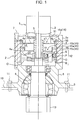
- a slewing drive device drives an upper slewing body serving as a driven portion in a shovel, and includes a motor 1 serving as a drive source and a speed reduction unit 2, as shown in Fig. 1 .
- the motor 1 and the speed reduction unit 2 are provided side by side in an axial direction (vertical direction) of the slewing drive device.
- the motor 1 is arranged above the speed reduction unit 2.
- the motor 1 is a hydraulic motor, or an electric motor.
- the motor 1 has a motor housing 3 configuring an outer surface of the motor 1, and a motor shaft 5 for outputting rotational force.
- the motor housing 3 has a flange 3a on a lower end thereof.
- the speed reduction unit 2 reduces speed of rotational force output from the motor 1, namely, rotational force of the motor shaft 5, and transmits the rotational force reduced in speed to the upper slewing body serving as the driven portion.
- the speed reduction unit 2 includes a cylindrical casing 4, a planetary gear mechanism 12 provided in the casing 4, and reducing the speed of the rotational force output from the motor 1, and a speed reduction output shaft 6 for outputting the rotational force reduced in speed by the planetary gear mechanism 12 to the upper slewing body.
- the motor 1 and the speed reduction unit 2 are coupled with each other in a state where a center of the motor shaft 5 and a center of the speed reduction output shaft 6 coincide with each other and these centers coincide with a shaft center of the slewing drive device. Furthermore, both the motor 1 and the speed reduction unit 2 are vertically arranged such that the motor shaft 5 and the speed reduction output shaft 6 extend in the axial direction (vertical direction) of the slewing drive device.
- the motor 1 and the speed reduction unit 2 are coupled with each other by fixing the flange 3a and the casing 4 with a plurality of coupling bolts 7 in a state where a lower end surface of the flange 3a of the motor housing 3 and an upper end surface of the casing 4 are in contact with each other. Note that only a single coupling bolt among the plurality of coupling bolts 7 is shown in Fig. 1 to Fig. 3 .
- a shaft supporting portion 8 is provided below the speed reduction unit 2 (casing 4).
- the shaft supporting portion 8 includes, therein, a bearing supporting the speed reduction output shaft 6 so as to allow the speed reduction output shaft 6 to be rotatable.
- a mounting flange 9 is provided on an outer circumference of a lower portion of the shaft supporting portion 8. This mounting flange 9 is mounted on an upper frame 10 of the upper slewing body by a plurality of mounting bolts 11.
- the speed reduction unit 2 includes a single stage planetary gear mechanism 12.
- the speed reduction unit may include a multi-stage planetary gear mechanism.
- the planetary gear mechanism 12 is simply referred to as the gear mechanism 12.
- Lubricant oil O for lubricating the gear mechanism 12 is injected into the casing 4.
- An oil surface of the lubricant oil O is located at such a level that most parts of the gear mechanism 12 are submerged under the oil surface, and becomes horizontal at the time of shutdown of the slewing drive device (see O1 in Fig. 1 and Fig. 2 ).
- the lubricant oil O is agitated by actuation of the gear mechanism 12, and centrifugal force is applied to the lubricant oil O by rotation of a sun gear S and a carrier C, described later, of the gear mechanism 12 and revolution of a plurality of planetary gears P, described later, of the gear mechanism 12.
- a part located near an outer circumference in the oil surface of the lubricant oil O climbs upward along an inner wall surface 4a of the casing 4 by this centrifugal force applied to the lubricant oil O.
- the whole oil surface becomes a mortar shape (see O2 in Fig. 1 and Fig. 3 ).
- the lubricant oil O scatters upward due to a pumping action of the gear mechanism 12.
- the lubricant climbing upward along the inner wall surface 4a of the casing 4 and the lubricant oil scattering upward are often referred to collectively as "rising lubricant oil”.
- the gear mechanism 12 has the sun gear S, the carrier (also referred to as a spider) C, the plurality of planetary gears P, and a ring gear R.
- the plurality of planetary gears P is supported by the carrier C so as to be arranged around the sun gear S.
- the ring gear R is provided on an inner circumference of the casing 4.
- Each planetary gear P performs revolution motion while rotating, as well known, so that the gear mechanism 12 reduces the speed of rotational force from the motor 1, and transmits the rotational force reduced in speed to the speed reduction output shaft 6.
- a pinion 13 provided on a lower end of the speed reduction output shaft 6 rotates while meshing with a gear (ring gear) for slewing, not shown in figures, and thereby the slewing drive device and the upper frame 10 coupled with the slewing drive device slew.
- an upper space 14 serving as an air chamber is provided above the gear mechanism 12 in the casing 4.
- the speed reduction unit 2 includes an oil receiver 15, a support member 16, and a cylindrical body 17 provided in the upper space 14.
- the oil receiver 15 and the support member 16 are provided so as to cover the gear mechanism 12 from above.
- the support member 16 supports the oil receiver 15 through the cylindrical body 17, and has a function as an auxiliary oil receiver as well.
- the oil receiver 15 and the support member 16 are configured so as to receive and store the lubricant oil rising during the operation of the slewing drive device, and gradually return the stored lubricant oil to the gear mechanism 12.
- configurations of the oil receiver 15 and the support member 16 will be described in detail with reference to Fig. 2 to Fig. 4 .
- the cylindrical body 17 having an inner diameter larger than an outer diameter of the motor shaft 5 is arranged, and this cylindrical body 17 is freely fitted on the motor shaft 5.
- the cylindrical body 17 is generally formed in a cylindrical shape, but may be formed in a square tube shape.
- Both the oil receiver 15 and the support member 16 are formed in slightly shallow and round container shapes.
- the oil receiver 15 is mounted on an outer circumference surface of a lower portion of the cylindrical body 17.
- the support member 16 is mounted on an outer circumference surface of an upper portion of the cylindrical body 17. That is, both the oil receiver 15 and the support member 16 are mounted on the outer circumference surface of the cylindrical body 17 so as to have a small clearance in a vertical direction therebetween.
- An outer circumference portion of the support member 16 is mounted on the casing 4 by bolting or the like in a state of being placed on the upper end surface of the casing 4.
- the support member 16 is supported by the casing 4, and the oil receiver 15 is supported by the casing 4 through the cylindrical body 17 and the support member 16.
- the support member 16 and the oil receiver 15 are arranged so as to be coaxial in the upper space 14 in a state of having a vertical position gap.
- the oil receiver 15 forms a main storage space 50 for storing lubricant oil.
- the main storage space 50 is located above a bottom wall 15c of the oil receiver 15, and surrounded by the bottom wall 15c of the oil receiver 15 and the outer circumference wall 15a of the oil receiver 15.
- the main storage space 50 has an upper portion which is opened, and the lubricant oil is fed into the main storage space 50 from the upper portion.
- the support member 16 forms an auxiliary storage space 51 for receiving and storing the lubricant oil rising beyond the oil receiver 15.
- the auxiliary storage space 51 is located above a bottom wall 16c of the support member 16, and surrounded by the bottom wall 16c of the support member 16 and an outer circumference wall 16a of the support member 16.
- the oil receiver 15 has an outer diameter smaller than the outer diameter of the support member 16.
- An oil passage 18 for guiding the rising lubricant oil to the main storage space 50 formed by the oil receiver 15 and the auxiliary storage space 51 formed by the support member 16 is formed between an outer circumference surface 15b of the oil receiver 15 and the inner wall surface 4a of the casing 4.
- This oil passage 18 is formed between the outer circumference surface 15b of the oil receiver 15 and the inner wall surface 4a of the casing 4, and is formed in a range covering whole circumferences of the outer circumference surface 15b and the inner wall surface 4a.
- This oil passage 18 is formed as a space extending in the axial direction of the oil receiver 15.
- the oil receiver 15 is provided with an oil drain hole 19 serving as an oil drain opening.
- the oil drain hole 19 is designed to gradually discharge the lubricant oil stored in the main storage space 50 toward the gear mechanism 12 through the oil drain hole 19.
- This oil drain hole 19 is formed so as to penetrate the bottom wall 15c of the oil receiver 15.
- the support member 16 is provided with oil outlet and inlet ports 20. These oil outlet and inlet ports 20 are formed so as to penetrate the bottom wall 16c of the support member 16.
- the lubricant oil O rising during the operation of the slewing drive device reaches above the oil receiver 15 through the oil passage 18, and the lubricant oil moving inward in the rising lubricant oil O falls on the oil receiver 15 due to its own weight to be stored in the main storage space 50. Then, the lubricant oil O stored in the main storage space 50 is gradually discharged through the oil drain hole 19.
- the lubricant oil O rising beyond the oil receiver 15 is guided above the support member 16 through the oil outlet and inlet ports 20 to be stored in the auxiliary storage space 51.
- the lubricant oil O stored in the auxiliary storage space 51 is discharged through the oil outlet and inlet ports 20 due to its own weight.
- the oil drain hole 19 has a diameter set such that the amount of the lubricant oil O discharged through the oil drain hole 19 per unit time is smaller than the amount of the lubricant oil O fed into the main storage space 50 per unit time.
- the diameter of the oil drain hole 19 is set such that it takes about 5 minutes to 10 minutes to discharge the lubricant oil O, which is stored in the main storage space 50, through the oil drain hole 19, even if the lubricant oil O is thin.
- an opening area of the oil drain hole 19 is set to an area of about 1% of a base area of the oil receiver 15.
- the oil drain hole 19 may be provided on only a single portion in the bottom wall 15c of the oil receiver 15, or may be provided on a plurality of portions.
- the diameter of each oil drain hole 19 should be set to such a diameter that the total amount of the lubricant oil O discharged through all of the oil drain holes 19 per unit time is smaller than the amount of the lubricant oil O fed into the main storage space 50 per unit time.
- the diameter of each oil drain hole 19 should be set to such a diameter that it takes about 5 minutes to 10 minutes to discharge the lubricant oil O, which is stored in the main storage space 50, through all of the oil drain holes 19, even if the lubricant oil O is thin.
- the total opening area of all of the oil drain holes 19 should be set to an area of about 1% of the base area of the oil receiver 15.
- the oil drain hole 19 is provided at such a position that the lubricant oil O discharged through the oil drain hole 19 drops, for example, on meshing parts of the sun gear S and the planetary gears P, in the gear mechanism 12. That is, the oil drain hole 19 is provided at a position near the inner circumference of the oil receiver 15.
- the oil outlet and inlet ports 20 of the support member 16 each have a diameter sufficiently larger than the diameter of the oil drain hole 19 in order to guide the rising lubricant oil O above the support member 16 through the oil outlet and inlet ports 20 effortlessly. Furthermore, in order to expand a range capable of guiding the lubricant oil O above the support member 16 in a circumferential direction of the support member 16, the plurality of oil outlet and inlet ports 20 are provided so as to be dispersed in a whole circumferential direction of the bottom wall 16c of the support member 16.
- each oil outlet and inlet port 20 is provided on a specific region in the bottom wall 16c of the support member 16, the specific region opposing to the oil receiver 15.
- An upper end portion 4a1 of the inner wall surface 4a of the casing 4 projects inwardly as shown in the figures.
- the outer circumference portion of the support member 16 is disposed so as to straddle the upper end portion 4a1 of the projecting inner wall surface 4a and the upper end surface of the casing 4.
- the lubricant oil O rising in the casing 4 is directly received by the oil receiver 15 in the casing 4 to be stored in the main storage space 50, and the lubricant oil O stored in the main storage space 50 is gradually returned downward through the oil drain hole 19, and hence the rising lubricant oil O is smoothly stored and returned as compared with a configuration in which lubricant oil is fed and stored into a tank outside a casing through a narrow upper passage, and the lubricant oil stored in the tank is returned into the casing through a lower passage connected to the upper passage, as in the publicly known techniques.
- the amount of the lubricant oil O to be agitated by the gear mechanism 12 is always reduced to a requisite minimum amount. Additionally, in a case where operation and shutdown of the slewing drive device are repeatedly performed in a short time, actuation of the gear mechanism 12 starts from a state where the lubricant oil O is not yet returned into a space where the gear mechanism 12 is placed, that is, a state where the oil surface of the lubricant oil O in the casing 4 is at a low level. Consequently, lubrication insufficiency of the gear mechanism 12 does not occur while reducing an energy loss caused by agitating the lubricant oil O with the gear mechanism 12.
- the slewing drive device in the slewing drive device according to the first embodiment, an extra external equipment or passage as in the publicly known techniques is unnecessary, and hence the structure can be simplified and reduced in size. As a result, it is possible to prevent considerable increase in the production cost of the slewing drive device and a negative influence on a layout around the slewing drive device. Furthermore, it is possible to increase the size of the oil receiver 15 within a range where the oil receiver is fit into the casing 4, and to sufficiently increase the capacity of the main storage space 50 formed by the oil receiver 15, and hence the aforementioned energy loss reduction effect can be further enhanced.
- an outer circumference wall 15a of an oil receiver 15 is tapered such that an upper portion is wider.
- an oil passage 18 is formed as a space with a bottom wide shape that has a narrower upper portion and grows wider from the upper portion toward a lower portion.
- the lower portion of the oil passage 18 is configured to be wider, so that rising lubricant oil O easily passes through the oil passage 18 from bottom to top, while the upper portion of the oil passage 18 is configured to be narrower, so that the lubricant oil O is unlikely to flow back from top to bottom. That is, a collecting effect and storage efficiency of the lubricant oil O by the oil receiver 15 can be further enhanced.
- the upper end portion 4al of the inner wall surface 4a of the casing 4 projects inward, and the outer circumference portion of the support member 16 is mounted on this projecting upper end portion 4a1
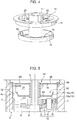
- an inner wall surface 4a of a casing 4 is formed to have no unevenness from a lower end to an upper end. Therefore, according to this second embodiment, the lubricant oil O is not prevented from rising due to an uneven shape of the inner wall surface 4a of the casing 4.
- the lubricant oil O is more smoothly fed into an auxiliary storage space 51 formed by the support member 16 and a main storage space 50 formed by the oil receiver 15.
- the support member 16 is formed in a simple disc-shape with no rising on its outer circumference portion, and the outer circumference portion of the support member 16 is mounted on the upper end portion of the casing 4 in a state where the outer circumference portion of the support member 16 is placed on the upper end surface of the casing 4. According to this configuration, the support member 16 can be easily fabricated and the production cost of the support member 16 can be reduced.
- the support member 16 is formed in the simple disc-shape, the lubricant oil O is stored on the support member 16.
- the auxiliary storage space 51 surrounded by the support member 16 and a flange 3a of a motor housing 3 is formed on the disc-shaped support member 16, and the lubricant oil O is stored in the auxiliary storage space 51.
- the support member 16 substantially has a function as an auxiliary oil receiver.
- a drive device for a construction machine is a drive device driving a driven portion in the construction machine, the drive device including: a motor serving as a drive source; and a speed reduction unit reducing speed of rotational force output from the motor, and transmitting the rotational force reduced in speed to the driven portion, wherein the motor has a motor shaft for outputting the rotational force, the speed reduction unit has a casing containing lubricant oil, a gear mechanism provided in the casing and reducing the speed of the rotational force output from the motor, a speed reduction output shaft for outputting the rotational force reduced in speed by the gear mechanism to the driven portion, and an oil receiver arranged above the gear mechanism in the casing, the oil receiver receiving the lubricant oil rising in the casing during operation of the drive device to store the lubricant oil, and the speed reduction unit and the motor are provided side by side such that a center of the speed reduction output shaft is aligned with a center of the motor shaft
- the lubricant oil rising in the casing is directly received by the oil receiver in the casing to be stored in the main storage space, and the lubricant oil stored in the main storage space is gradually returned to the gear mechanism side through the oil drain opening, and hence the lubricant oil is smoothly stored and returned as compared with a configuration in which lubricant oil is fed and stored into a tank outside a casing through a narrow upper passage, and the lubricant oil stored in the tank is returned into the casing through a lower passage, as in the publicly known techniques.
- the amount of the lubricant oil to be agitated by the gear mechanism is always reduced to a requisite minimum amount.
- actuation of the gear mechanism starts from a state where the lubricant oil is not yet returned into a space where the gear mechanism is provided in the casing, that is, a state where the oil surface of the lubricant oil in the casing is at a low level. Consequently, lubrication insufficiency of the gear mechanism does not occur while reducing an energy loss caused by agitating the lubricant oil with the gear mechanism.
- an extra external equipment or passage as in the publicly known techniques is unnecessary, and hence the structure of the drive device can be simplified, and the drive device can be reduced in size.
- the oil receiver is desirably a container centering on the motor shaft and expanding radially outward of the motor shaft, and is desirably provided in a state of covering the gear mechanism from above.
- the rising lubricant oil can be smoothly guided toward the inner wall surface of the casing. Therefore, even when agitating force generated from the gear mechanism is small, the oil surface of the lubricant oil can be easily formed in a mortar shape. Consequently, an energy saving effect and a lubricant oil collecting effect can be enhanced.
- the oil passage is desirably formed between the inner wall surface of the casing and the outer surface of the oil receiver, and is desirably formed in a range covering respective whole circumferences of the inner wall surface and the outer surface.
- the rising lubricant oil can be guided toward the main storage space formed by the oil receiver in the range covering the whole circumferences of the inner wall surface of the casing and the outer circumference surface of the oil receiver. This enhances the efficiency of lubricant oil storage by means of the oil receiver.
- the oil passage desirably has a bottom wide shape which grows wider from an upper portion toward a lower portion.
- the lower portion of the oil passage is configured to be wider, so that the rising lubricant oil easily passes through the oil passage from bottom to top, while the upper portion of the oil passage is configured to be narrower, so that the lubricant oil is unlikely to flow back from top to bottom. Consequently, according to the present configuration, a collecting effect and storage efficiency of the lubricant oil by the oil receiver can be further enhanced.
- the oil receiver desirably has a bottom wall arranged above the gear mechanism, and the oil drain opening is desirably a hole provided on the bottom wall to discharge a specific amount of the lubricant oil per unit time, the specific amount being smaller than an amount of the lubricant oil fed into the main storage space per unit time.
- the lubricant oil stored in the main storage space can be discharged by the simple hole provided on the bottom wall of the oil receiver, and hence the structure of the oil receiver can be simplified.
- the oil receiver can be easily fabricated, and the production cost of the oil receiver can be suppressed.
- oil drain opening is the hole provided on the bottom wall of the oil receiver, and therefore clogging occurring in a case of a duct line or a long passage does not occur.
- the oil drain opening is desirably arranged at such a position that the lubricant oil discharged through the oil drain opening drops toward the gear mechanism.
- the oil stored in the main storage space is directly returned to the gear mechanism through the oil drain opening, and hence in a state where the level of the oil surface of the lubricant oil in the casing is lowered, the lubricant state of the gear mechanism can be kept.
- the speed reduction unit desirably has a cylindrical body freely fitted on the motor shaft in a space above the gear mechanism in the casing, and a support member arranged above the oil receiver and mounted on the casing to support the cylindrical body, and the oil receiver is desirably mounted on an outer circumference portion of the cylindrical body to be thereby supported with the casing through the cylindrical body and the support member.
- the support member desirably forms an auxiliary storage space for receiving and storing the lubricant oil rising beyond the oil receiver, and the support member is desirably provided with an oil inlet port for feeding the lubricant oil into the auxiliary storage space, and an oil outlet port for discharging the lubricant oil stored in the auxiliary storage space.
- the storage capacity of the lubricant oil can be increased by the support member.
- the oil outlet port is desirably arranged at such a position that the lubricant oil discharged from the auxiliary storage space through the oil outlet port flows and falls toward the oil receiver.
- the lubricant oil stored in the auxiliary storage space is returned to the gear mechanism through the oil receiver, and hence an effect of delaying the return of whole the lubricant oil rising in the casing to the gear mechanism can be improved.
- the support member desirably forms an auxiliary storage space for receiving and storing the lubricant oil rising beyond the oil receiver, and the support member is desirably provided with an oil outlet and inlet port functioning as both an oil inlet port for feeding the lubricant oil into the auxiliary storage space, and an oil outlet port for discharging the lubricant oil stored in the auxiliary storage space.
- the storage capacity of the lubricant oil can be increased by the support member.
- the oil outlet and inlet port provided on the support member combines the oil inlet port for feeding the lubricant oil into the auxiliary storage space, and the oil outlet port for discharging the lubricant oil stored in the auxiliary storage space, and hence the structure of the support member can be simplified. Consequently, the support member can be easily fabricated.
- the oil outlet and inlet port is desirably arranged at such a position that the lubricant oil discharged from the auxiliary storage space through the oil outlet and inlet port flows and falls toward the oil receiver.
- the lubricant oil stored in the auxiliary storage space is returned to the gear mechanism through the oil receiver, and hence an effect of delaying the return of whole the lubricant oil rising in the casing to the gear mechanism can be improved.
- the casing desirably has an upper end portion on which an outer circumference portion of the support member is mounted, and the inner wall surface of the casing is desirably formed to have no unevenness from a lower end to an upper end.
- the lubricant oil is not prevented from rising due to the uneven shape of the inner wall surface of the casing, and hence the lubricant oil is more smoothly fed into the main storage space formed by the oil receiver and an auxiliary storage space formed by the support member.
- both reduction in an energy loss caused by agitating the lubricant oil with the gear mechanism and ensuring of lubrication of the gear mechanism can be attained, and simplification of the structure of the drive device and downsizing of the drive device can be achieved.
Landscapes
- Engineering & Computer Science (AREA)
- General Engineering & Computer Science (AREA)
- Mechanical Engineering (AREA)
- Mining & Mineral Resources (AREA)
- Civil Engineering (AREA)
- Structural Engineering (AREA)
- General Details Of Gearings (AREA)
- Component Parts Of Construction Machinery (AREA)
Claims (11)
- Antriebsvorrichtung für eine Baumaschine, wobei die Antriebsvorrichtung einen angetriebenen Abschnitt in der Baumaschine antreibt, wobei die Antriebsvorrichtung Folgendes aufweist:einen Motor (1), der als eine Antriebsquelle dient; undeine Drehzahlreduktionseinheit (2), die eine Drehzahl einer von dem Motor (1) abgegebenen Drehkraft reduziert und die drehzahlreduzierte Drehkraft an den angetriebenen Abschnitt überträgt, wobeider Motor (1) eine Motorwelle (5) zum Abgeben der Drehkraft hat,die Drehzahlreduktionseinheit (2) ein Gehäuse (4), das Schmieröl enthält, einen Getriebemechanismus (12), der in dem Gehäuse (4) vorgesehen ist und die Drehzahl der von dem Motor (1) abgegebenen Drehkraft reduziert, eine Drehzahlreduktionsausgangswelle (6) zum Abgeben der Drehzahlreduzierten Drehkraft durch den Getriebemechanismus (12) an den angetriebenen Abschnitt, und einen Ölsammler (15) hat, der oberhalb des Getriebemechanismus (12) in dem Gehäuse (4) angeordnet ist, wobei der Ölsammler (15) das Schmieröl, das während eines Betriebs der Antriebsvorrichtung in dem Gehäuse (4) aufsteigt, aufnimmt, um das Schmieröl zu speichern, und die Drehzahlreduktionseinheit (2) und der Motor (1) nebeneinander vorgesehen sind, sodass ein Mittelpunkt der Drehzahlreduktionsausgangswelle mit einem Mittelpunkt der Motorwelle (5) in einer vertikalen Richtung ausgerichtet ist, wobei der Getriebemechanismus (12) in dem Schmieröl untergetaucht ist, das in dem Innenraum des Gehäuses (4) enthalten ist,der Ölsammler (15) einen Hauptspeicherraum (50) zum Speichern des Schmieröls ausbildet und in dem Gehäuse (4) so angeordnet ist, dass ein Öldurchgang (18) zum Führen des aufsteigenden Schmieröls zu dem Hauptspeicherraum (50) zwischen einer Außenfläche des Ölsammlers (15) und einer Innenwandfläche des Gehäuses (4) ausgebildet ist, undder Ölsammler (15) mit einer Ölablassöffnung (19) versehen ist, wobei die Ölablassöffnung (19) so gestaltet ist, dass sie das in dem Hauptspeicherraum (50) gespeicherte Schmieröl in Richtung des Getriebemechanismus (12) durch die Ölablassöffnung (19) allmählich ablässt, dadurch gekennzeichnet, dassdie Drehzahlreduktionseinheit (2) einen Zylinderkörper (17), der in einem Raum oberhalb des Getriebemechanismus (12) in dem Gehäuse (4) lose auf die Motorwelle (5) aufgesetzt ist, und ein Stützbauteil (16) hat, das oberhalb des Ölsammlers (15) angeordnet und an dem Gehäuse (4) so montiert ist, dass es den Zylinderkörper (17) stützt, wobei der Zylinderkörper (17) einen Innendurchmesser hat, der größer ist als ein Außendurchmesser der Motorwelle (5), um die Motorwelle (5) durch den Zylinderkörper (17) einsetzen zu können, undder Ölsammler (15) an einem Außenumfangsabschnitt des Zylinderkörpers (17) montiert ist.
- Antriebsvorrichtung für eine Baumaschine nach Anspruch 1, wobei
der Ölsammler (15) ein Behälter ist, der auf die Motorwelle (5) zentriert ist und sich von der Motorwelle (5) radial nach außen ausdehnt, und in einem Zustand vorgesehen ist, in dem er den Getriebemechanismus (12) von oben abdeckt. - Antriebsvorrichtung für eine Baumaschine nach Anspruch 1 oder 2, wobei
der Öldurchgang (18) zwischen der Innenwandfläche (4a) des Gehäuses (4) und der Außenfläche des Ölsammlers (15) ausgebildet ist und in einem Bereich ausgebildet ist, der jeweils einen ganzen Umfang der Innenwandfläche (4a) und der Außenfläche abdeckt. - Antriebsvorrichtung für eine Baumaschine nach Anspruch 3, wobei
der Öldurchgang (18) eine bodenbreite Form hat, die von dem oberen Abschnitt in Richtung eines unteren Abschnitts breiter wird. - Antriebsvorrichtung für eine Baumaschine nach einem der Ansprüche 1 bis 4, wobei
der Ölsammler (15) eine Bodenwand (15c) hat, die oberhalb des Getriebemechanismus (12) angeordnet ist, und
die Ölablassöffnung (19) ein Loch ist, das in der Bodenwand (15c) vorgesehen ist, um eine bestimmte Menge des Schmieröls pro Zeiteinheit abzugeben, wobei die bestimmte Menge kleiner ist als eine Menge des Schmieröls, die pro Zeiteinheit in den Hauptspeicherraum (15) zugeführt wird. - Antriebsvorrichtung für eine Baumaschine nach einem der Ansprüche 1 bis 5, wobei
die Ölablassöffnung (19) an einer solchen Position angeordnet ist, dass das durch die Ölablassöffnung (19) abgegebene Schmieröl in Richtung des Getriebemechanismus (12) tropft. - Antriebsvorrichtung für eine Baumaschine nach Anspruch 6, wobei
das Stützbauteil (16) einen Hilfsspeicherraum (51) zum Aufnehmen und Speichern des Schmieröls ausbildet, das über den Ölsammler (15) hinaus aufsteigt, und
das Stützbauteil (16) mit einem Öleinlassanschluss zum Zuführen des Schmieröls in den Hilfsspeicherraum (51), und einem Ölauslassanschluss zum Abgeben des Schmieröls versehen ist, das in dem Hilfsspeicherraum (51) gespeichert ist. - Antriebsvorrichtung für eine Baumaschine nach Anspruch 7, wobei
der Ölauslassanschluss an einer solchen Position angeordnet ist, dass das von dem Hilfsspeicherraum (51) abgegebene Schmieröl durch den Ölauslassanschluss fließt und in Richtung des Ölsammlers (15) sinkt. - Antriebsvorrichtung für eine Baumaschine nach Anspruch 1, wobei
das Stützbauteil (16) einen Hilfsspeicherraum (51) zum Aufnehmen und Speichern des Schmieröls ausbildet, das über den Ölsammler (15) hinaus aufsteigt, und
das Stützbauteil (16) mit einem Öl-Auslass-Und-Einlass-Anschluss versehen ist, der sowohl als ein Öleinlassanschluss zum Zuführen des Schmieröls in den Hilfsspeicherraum (51) als auch als ein Ölauslassanschluss zum Abgeben des Schmieröls dient, das in dem Hilfsspeicherraum (51) gespeichert ist. - Antriebsvorrichtung für eine Baumaschine nach Anspruch 9, wobei
der Öl-Auslass-Und-Einlass-Anschluss an einer solchen Position angeordnet ist, dass das von dem Hilfsspeicherraum (51) abgegebene Schmieröl durch den Öl-Auslass-Und-Einlass-Anschluss fließt und in Richtung des Ölsammlers (15) sinkt. - Antriebsvorrichtung für eine Baumaschine nach einem der Ansprüche 1 bis 10, wobei
das Gehäuse (4) einen oberen Endabschnitt (4a1) hat, an dem ein Außenumfangsabschnitt des Stützbauteils (16) montiert ist, und
die Innenwandfläche (4a) des Gehäuses (4) so ausgebildet ist, dass sie von einem unteren Ende zu einem oberen Ende keine Unebenheit hat.
Applications Claiming Priority (1)
| Application Number | Priority Date | Filing Date | Title |
|---|---|---|---|
| JP2011272022A JP5816071B2 (ja) | 2011-12-13 | 2011-12-13 | 建設機械の駆動装置 |
Publications (3)
| Publication Number | Publication Date |
|---|---|
| EP2604759A2 EP2604759A2 (de) | 2013-06-19 |
| EP2604759A3 EP2604759A3 (de) | 2017-04-12 |
| EP2604759B1 true EP2604759B1 (de) | 2019-11-06 |
Family
ID=47561094
Family Applications (1)
| Application Number | Title | Priority Date | Filing Date |
|---|---|---|---|
| EP12196448.0A Not-in-force EP2604759B1 (de) | 2011-12-13 | 2012-12-11 | Antriebsvorrichtung für eine Baumaschine |
Country Status (4)
| Country | Link |
|---|---|
| US (1) | US9328817B2 (de) |
| EP (1) | EP2604759B1 (de) |
| JP (1) | JP5816071B2 (de) |
| CN (1) | CN103161923B (de) |
Families Citing this family (8)
| Publication number | Priority date | Publication date | Assignee | Title |
|---|---|---|---|---|
| CN105492282B (zh) * | 2013-08-27 | 2018-02-23 | 株式会社神户制钢所 | 动力控制装置及具备该装置的混合动力工程机械 |
| DE102014012880B4 (de) | 2013-09-17 | 2021-09-30 | Sew-Eurodrive Gmbh & Co Kg | Antrieb |
| JP6585070B2 (ja) * | 2014-03-18 | 2019-10-02 | ジーイー・アーヴィオ・ソチエタ・レスポンサビリタ・リミタータGe Avio Srl | 特にエピサイクリック・トランスミッション用の、静止部から回転部へと潤滑オイルを流すためのオイル移送アセンブリ |
| JP6188615B2 (ja) * | 2014-03-27 | 2017-08-30 | アイシン・エィ・ダブリュ株式会社 | 動力伝達装置 |
| DE102015012132A1 (de) * | 2015-09-17 | 2017-03-23 | Liebherr-Components Biberach Gmbh | Antriebsvorrichtung mit Umlauffilterung |
| US10494998B2 (en) * | 2017-01-30 | 2019-12-03 | United Technologies Corporation | Lubrication of epicyclic gear system for gas turbine engine |
| US10697586B2 (en) * | 2017-08-23 | 2020-06-30 | Bell Helicopter Textron Inc. | Supplemental lubrication pressurized by component or reservoir rotation |
| DE102021209206A1 (de) * | 2021-08-23 | 2023-02-23 | Zf Friedrichshafen Ag | Getriebe für ein Kraftfahrzeug |
Family Cites Families (23)
| Publication number | Priority date | Publication date | Assignee | Title |
|---|---|---|---|---|
| US2214485A (en) * | 1939-03-23 | 1940-09-10 | Westinghouse Electric & Mfg Co | Gear lubrication apparatus |
| US2930448A (en) * | 1958-10-08 | 1960-03-29 | Fort Worth Steel And Machinery | Oil metering device |
| US3529698A (en) * | 1967-05-05 | 1970-09-22 | Gen Electric | Self-operating lubrication system for gear drive units |
| GB1417592A (en) * | 1972-03-27 | 1975-12-10 | Caterpillar Tractor Co | Drive transmission apparatus |
| US3819018A (en) * | 1972-12-04 | 1974-06-25 | Caterpillar Tractor Co | Brake assembly for excavator swing transmission |
| JPS5884260A (ja) * | 1981-09-11 | 1983-05-20 | Toyota Motor Corp | 自動車用自動変速機 |
| DE3209514C2 (de) * | 1982-03-16 | 1984-04-26 | BHS-Bayerische Berg-, Hütten- und Salzwerke AG, 8000 München | In sich geschlossene Getriebeanlage mit Druckschmierung |
| JPH0745745B2 (ja) * | 1989-03-23 | 1995-05-17 | 油谷重工株式会社 | 旋回減速機 |
| FR2658577A1 (fr) * | 1990-02-20 | 1991-08-23 | Aerospatiale | Dispositif de lubrification de secours pour reducteur notamment pour boite de transmission principale de giravion. |
| SE509564C2 (sv) * | 1997-02-19 | 1999-02-08 | Atlas Copco Tools Ab | Motorverktyg med smord vinkelväxel |
| FR2798983B1 (fr) * | 1999-09-10 | 2001-11-23 | Eurocopter France | Dispositif de lubrification d'un ensemble mecanique multiplicateur-reducteur |
| GB0106003D0 (en) * | 2001-03-12 | 2001-05-02 | Hansen Transmissions Int | Lubrication system |
| JP2004125092A (ja) | 2002-10-03 | 2004-04-22 | Hitachi Constr Mach Co Ltd | 油圧モータ用減速機の潤滑装置 |
| JP4532250B2 (ja) | 2004-12-09 | 2010-08-25 | 日立建機株式会社 | 減速機付き油圧モータ |
| JP4667090B2 (ja) | 2005-03-16 | 2011-04-06 | ヤマハ発動機株式会社 | ハイブリッド車両の駆動ユニット、ハイブリッド車両及び二輪車 |
| JP2006275163A (ja) * | 2005-03-29 | 2006-10-12 | Fuji Heavy Ind Ltd | 車両変速機の潤滑油面調整装置 |
| JP4608384B2 (ja) | 2005-08-03 | 2011-01-12 | 株式会社小松製作所 | 旋回駆動装置、旋回制御装置、旋回制御方法、および建設機械 |
| JP4619257B2 (ja) * | 2005-10-03 | 2011-01-26 | トヨタ自動車株式会社 | 自動変速機 |
| US7866444B2 (en) * | 2006-04-06 | 2011-01-11 | Fairfield Manufacturing Company, Inc. | Cascading oil flow bearing lubrication device |
| US20080135339A1 (en) | 2006-11-17 | 2008-06-12 | Miller Kent A | Method and apparatus for cooling and lubricating an off-axis motor/generator |
| JP4782716B2 (ja) * | 2007-03-20 | 2011-09-28 | 株式会社小松製作所 | 電動旋回装置 |
| JP4782715B2 (ja) * | 2007-03-20 | 2011-09-28 | 株式会社小松製作所 | 電動旋回装置 |
| JP5496767B2 (ja) | 2010-05-08 | 2014-05-21 | 日立建機株式会社 | 建設機械の旋回装置 |
-
2011
- 2011-12-13 JP JP2011272022A patent/JP5816071B2/ja not_active Expired - Fee Related
-
2012
- 2012-12-11 EP EP12196448.0A patent/EP2604759B1/de not_active Not-in-force
- 2012-12-11 US US13/710,869 patent/US9328817B2/en not_active Expired - Fee Related
- 2012-12-13 CN CN201210539614.8A patent/CN103161923B/zh not_active Expired - Fee Related
Non-Patent Citations (1)
| Title |
|---|
| None * |
Also Published As
| Publication number | Publication date |
|---|---|
| CN103161923A (zh) | 2013-06-19 |
| JP5816071B2 (ja) | 2015-11-17 |
| US20130145880A1 (en) | 2013-06-13 |
| EP2604759A3 (de) | 2017-04-12 |
| CN103161923B (zh) | 2015-12-09 |
| JP2013124680A (ja) | 2013-06-24 |
| US9328817B2 (en) | 2016-05-03 |
| EP2604759A2 (de) | 2013-06-19 |
Similar Documents
| Publication | Publication Date | Title |
|---|---|---|
| EP2604759B1 (de) | Antriebsvorrichtung für eine Baumaschine | |
| EP2322766B1 (de) | Ölauffang- und Bypasssystem | |
| KR101751865B1 (ko) | 건설기계의 선회 장치 | |
| JP5274703B1 (ja) | 洗濯機 | |
| JP4981694B2 (ja) | 動力伝達装置 | |
| US8172515B2 (en) | Turbo vacuum pump | |
| JP5315279B2 (ja) | 減速機及び旋回装置 | |
| CN104246310A (zh) | 工程机械的驱动装置 | |
| JP2011236950A5 (de) | ||
| JP2011522994A (ja) | ターボブロア及びこれに使用される高速回転体 | |
| US12181036B2 (en) | Transmission device | |
| US8152675B2 (en) | Device for optimizing the feed function of the ring gear of a differential with regard to the maximum flow rate | |
| US12181032B2 (en) | Transmission device | |
| EP2691653B1 (de) | Verdichter | |
| JP2013060976A (ja) | 終減速装置の潤滑構造 | |
| US12196295B2 (en) | Transmission device | |
| CN110469645A (zh) | 一种半同轴式电驱桥总成 | |
| JP2020011190A (ja) | エアセパレータ及びそれを備えた動力伝達装置 | |
| JP2011236915A (ja) | 遠心ポンプ用羽根車及びそれを備えた遠心ポンプ | |
| KR102927235B1 (ko) | 유성기어감속장치 일체형 원심펌프 | |
| CN221196033U (zh) | 电驱行星减速箱动力装置 | |
| US20220316561A1 (en) | Speed reducer and construction machine | |
| KR20250175030A (ko) | 테이블 피더 | |
| CN121036421A (zh) | 电驱动系统油泵防吸空结构 | |
| JP2019152244A (ja) | 駆動装置 |
Legal Events
| Date | Code | Title | Description |
|---|---|---|---|
| PUAI | Public reference made under article 153(3) epc to a published international application that has entered the european phase |
Free format text: ORIGINAL CODE: 0009012 |
|
| AK | Designated contracting states |
Kind code of ref document: A2 Designated state(s): AL AT BE BG CH CY CZ DE DK EE ES FI FR GB GR HR HU IE IS IT LI LT LU LV MC MK MT NL NO PL PT RO RS SE SI SK SM TR |
|
| AX | Request for extension of the european patent |
Extension state: BA ME |
|
| PUAL | Search report despatched |
Free format text: ORIGINAL CODE: 0009013 |
|
| AK | Designated contracting states |
Kind code of ref document: A3 Designated state(s): AL AT BE BG CH CY CZ DE DK EE ES FI FR GB GR HR HU IE IS IT LI LT LU LV MC MK MT NL NO PL PT RO RS SE SI SK SM TR |
|
| AX | Request for extension of the european patent |
Extension state: BA ME |
|
| RIC1 | Information provided on ipc code assigned before grant |
Ipc: E02F 9/12 20060101AFI20170306BHEP |
|
| STAA | Information on the status of an ep patent application or granted ep patent |
Free format text: STATUS: REQUEST FOR EXAMINATION WAS MADE |
|
| 17P | Request for examination filed |
Effective date: 20170918 |
|
| RBV | Designated contracting states (corrected) |
Designated state(s): AL AT BE BG CH CY CZ DE DK EE ES FI FR GB GR HR HU IE IS IT LI LT LU LV MC MK MT NL NO PL PT RO RS SE SI SK SM TR |
|
| GRAP | Despatch of communication of intention to grant a patent |
Free format text: ORIGINAL CODE: EPIDOSNIGR1 |
|
| STAA | Information on the status of an ep patent application or granted ep patent |
Free format text: STATUS: GRANT OF PATENT IS INTENDED |
|
| INTG | Intention to grant announced |
Effective date: 20190523 |
|
| RIN1 | Information on inventor provided before grant (corrected) |
Inventor name: UCHIYAMA, RYO Inventor name: YOICHI, SHOJI Inventor name: KAWABATA, MASASHI Inventor name: HAMASAKI, MASATSUGU Inventor name: YAMASHITA, KOJI |
|
| GRAS | Grant fee paid |
Free format text: ORIGINAL CODE: EPIDOSNIGR3 |
|
| GRAA | (expected) grant |
Free format text: ORIGINAL CODE: 0009210 |
|
| STAA | Information on the status of an ep patent application or granted ep patent |
Free format text: STATUS: THE PATENT HAS BEEN GRANTED |
|
| AK | Designated contracting states |
Kind code of ref document: B1 Designated state(s): AL AT BE BG CH CY CZ DE DK EE ES FI FR GB GR HR HU IE IS IT LI LT LU LV MC MK MT NL NO PL PT RO RS SE SI SK SM TR |
|
| REG | Reference to a national code |
Ref country code: GB Ref legal event code: FG4D |
|
| REG | Reference to a national code |
Ref country code: CH Ref legal event code: EP Ref country code: AT Ref legal event code: REF Ref document number: 1198893 Country of ref document: AT Kind code of ref document: T Effective date: 20191115 |
|
| REG | Reference to a national code |
Ref country code: IE Ref legal event code: FG4D |
|
| REG | Reference to a national code |
Ref country code: DE Ref legal event code: R096 Ref document number: 602012065402 Country of ref document: DE |
|
| REG | Reference to a national code |
Ref country code: NL Ref legal event code: MP Effective date: 20191106 |
|
| REG | Reference to a national code |
Ref country code: LT Ref legal event code: MG4D |
|
| PG25 | Lapsed in a contracting state [announced via postgrant information from national office to epo] |
Ref country code: NO Free format text: LAPSE BECAUSE OF FAILURE TO SUBMIT A TRANSLATION OF THE DESCRIPTION OR TO PAY THE FEE WITHIN THE PRESCRIBED TIME-LIMIT Effective date: 20200206 Ref country code: PT Free format text: LAPSE BECAUSE OF FAILURE TO SUBMIT A TRANSLATION OF THE DESCRIPTION OR TO PAY THE FEE WITHIN THE PRESCRIBED TIME-LIMIT Effective date: 20200306 Ref country code: FI Free format text: LAPSE BECAUSE OF FAILURE TO SUBMIT A TRANSLATION OF THE DESCRIPTION OR TO PAY THE FEE WITHIN THE PRESCRIBED TIME-LIMIT Effective date: 20191106 Ref country code: BG Free format text: LAPSE BECAUSE OF FAILURE TO SUBMIT A TRANSLATION OF THE DESCRIPTION OR TO PAY THE FEE WITHIN THE PRESCRIBED TIME-LIMIT Effective date: 20200206 Ref country code: SE Free format text: LAPSE BECAUSE OF FAILURE TO SUBMIT A TRANSLATION OF THE DESCRIPTION OR TO PAY THE FEE WITHIN THE PRESCRIBED TIME-LIMIT Effective date: 20191106 Ref country code: LV Free format text: LAPSE BECAUSE OF FAILURE TO SUBMIT A TRANSLATION OF THE DESCRIPTION OR TO PAY THE FEE WITHIN THE PRESCRIBED TIME-LIMIT Effective date: 20191106 Ref country code: PL Free format text: LAPSE BECAUSE OF FAILURE TO SUBMIT A TRANSLATION OF THE DESCRIPTION OR TO PAY THE FEE WITHIN THE PRESCRIBED TIME-LIMIT Effective date: 20191106 Ref country code: GR Free format text: LAPSE BECAUSE OF FAILURE TO SUBMIT A TRANSLATION OF THE DESCRIPTION OR TO PAY THE FEE WITHIN THE PRESCRIBED TIME-LIMIT Effective date: 20200207 Ref country code: LT Free format text: LAPSE BECAUSE OF FAILURE TO SUBMIT A TRANSLATION OF THE DESCRIPTION OR TO PAY THE FEE WITHIN THE PRESCRIBED TIME-LIMIT Effective date: 20191106 Ref country code: ES Free format text: LAPSE BECAUSE OF FAILURE TO SUBMIT A TRANSLATION OF THE DESCRIPTION OR TO PAY THE FEE WITHIN THE PRESCRIBED TIME-LIMIT Effective date: 20191106 Ref country code: NL Free format text: LAPSE BECAUSE OF FAILURE TO SUBMIT A TRANSLATION OF THE DESCRIPTION OR TO PAY THE FEE WITHIN THE PRESCRIBED TIME-LIMIT Effective date: 20191106 |
|
| PG25 | Lapsed in a contracting state [announced via postgrant information from national office to epo] |
Ref country code: IS Free format text: LAPSE BECAUSE OF FAILURE TO SUBMIT A TRANSLATION OF THE DESCRIPTION OR TO PAY THE FEE WITHIN THE PRESCRIBED TIME-LIMIT Effective date: 20200306 Ref country code: HR Free format text: LAPSE BECAUSE OF FAILURE TO SUBMIT A TRANSLATION OF THE DESCRIPTION OR TO PAY THE FEE WITHIN THE PRESCRIBED TIME-LIMIT Effective date: 20191106 Ref country code: RS Free format text: LAPSE BECAUSE OF FAILURE TO SUBMIT A TRANSLATION OF THE DESCRIPTION OR TO PAY THE FEE WITHIN THE PRESCRIBED TIME-LIMIT Effective date: 20191106 |
|
| PG25 | Lapsed in a contracting state [announced via postgrant information from national office to epo] |
Ref country code: AL Free format text: LAPSE BECAUSE OF FAILURE TO SUBMIT A TRANSLATION OF THE DESCRIPTION OR TO PAY THE FEE WITHIN THE PRESCRIBED TIME-LIMIT Effective date: 20191106 |
|
| PG25 | Lapsed in a contracting state [announced via postgrant information from national office to epo] |
Ref country code: EE Free format text: LAPSE BECAUSE OF FAILURE TO SUBMIT A TRANSLATION OF THE DESCRIPTION OR TO PAY THE FEE WITHIN THE PRESCRIBED TIME-LIMIT Effective date: 20191106 Ref country code: DK Free format text: LAPSE BECAUSE OF FAILURE TO SUBMIT A TRANSLATION OF THE DESCRIPTION OR TO PAY THE FEE WITHIN THE PRESCRIBED TIME-LIMIT Effective date: 20191106 Ref country code: RO Free format text: LAPSE BECAUSE OF FAILURE TO SUBMIT A TRANSLATION OF THE DESCRIPTION OR TO PAY THE FEE WITHIN THE PRESCRIBED TIME-LIMIT Effective date: 20191106 Ref country code: CZ Free format text: LAPSE BECAUSE OF FAILURE TO SUBMIT A TRANSLATION OF THE DESCRIPTION OR TO PAY THE FEE WITHIN THE PRESCRIBED TIME-LIMIT Effective date: 20191106 |
|
| REG | Reference to a national code |
Ref country code: CH Ref legal event code: PL |
|
| REG | Reference to a national code |
Ref country code: DE Ref legal event code: R097 Ref document number: 602012065402 Country of ref document: DE |
|
| REG | Reference to a national code |
Ref country code: AT Ref legal event code: MK05 Ref document number: 1198893 Country of ref document: AT Kind code of ref document: T Effective date: 20191106 |
|
| REG | Reference to a national code |
Ref country code: BE Ref legal event code: MM Effective date: 20191231 |
|
| PG25 | Lapsed in a contracting state [announced via postgrant information from national office to epo] |
Ref country code: SM Free format text: LAPSE BECAUSE OF FAILURE TO SUBMIT A TRANSLATION OF THE DESCRIPTION OR TO PAY THE FEE WITHIN THE PRESCRIBED TIME-LIMIT Effective date: 20191106 Ref country code: MC Free format text: LAPSE BECAUSE OF FAILURE TO SUBMIT A TRANSLATION OF THE DESCRIPTION OR TO PAY THE FEE WITHIN THE PRESCRIBED TIME-LIMIT Effective date: 20191106 Ref country code: SK Free format text: LAPSE BECAUSE OF FAILURE TO SUBMIT A TRANSLATION OF THE DESCRIPTION OR TO PAY THE FEE WITHIN THE PRESCRIBED TIME-LIMIT Effective date: 20191106 |
|
| PLBE | No opposition filed within time limit |
Free format text: ORIGINAL CODE: 0009261 |
|
| STAA | Information on the status of an ep patent application or granted ep patent |
Free format text: STATUS: NO OPPOSITION FILED WITHIN TIME LIMIT |
|
| 26N | No opposition filed |
Effective date: 20200807 |
|
| PG25 | Lapsed in a contracting state [announced via postgrant information from national office to epo] |
Ref country code: IE Free format text: LAPSE BECAUSE OF NON-PAYMENT OF DUE FEES Effective date: 20191211 Ref country code: LU Free format text: LAPSE BECAUSE OF NON-PAYMENT OF DUE FEES Effective date: 20191211 |
|
| PG25 | Lapsed in a contracting state [announced via postgrant information from national office to epo] |
Ref country code: BE Free format text: LAPSE BECAUSE OF NON-PAYMENT OF DUE FEES Effective date: 20191231 Ref country code: AT Free format text: LAPSE BECAUSE OF FAILURE TO SUBMIT A TRANSLATION OF THE DESCRIPTION OR TO PAY THE FEE WITHIN THE PRESCRIBED TIME-LIMIT Effective date: 20191106 Ref country code: LI Free format text: LAPSE BECAUSE OF NON-PAYMENT OF DUE FEES Effective date: 20191231 Ref country code: CH Free format text: LAPSE BECAUSE OF NON-PAYMENT OF DUE FEES Effective date: 20191231 Ref country code: SI Free format text: LAPSE BECAUSE OF FAILURE TO SUBMIT A TRANSLATION OF THE DESCRIPTION OR TO PAY THE FEE WITHIN THE PRESCRIBED TIME-LIMIT Effective date: 20191106 |
|
| PG25 | Lapsed in a contracting state [announced via postgrant information from national office to epo] |
Ref country code: CY Free format text: LAPSE BECAUSE OF FAILURE TO SUBMIT A TRANSLATION OF THE DESCRIPTION OR TO PAY THE FEE WITHIN THE PRESCRIBED TIME-LIMIT Effective date: 20191106 |
|
| PG25 | Lapsed in a contracting state [announced via postgrant information from national office to epo] |
Ref country code: HU Free format text: LAPSE BECAUSE OF FAILURE TO SUBMIT A TRANSLATION OF THE DESCRIPTION OR TO PAY THE FEE WITHIN THE PRESCRIBED TIME-LIMIT; INVALID AB INITIO Effective date: 20121211 Ref country code: MT Free format text: LAPSE BECAUSE OF FAILURE TO SUBMIT A TRANSLATION OF THE DESCRIPTION OR TO PAY THE FEE WITHIN THE PRESCRIBED TIME-LIMIT Effective date: 20191106 |
|
| PG25 | Lapsed in a contracting state [announced via postgrant information from national office to epo] |
Ref country code: TR Free format text: LAPSE BECAUSE OF FAILURE TO SUBMIT A TRANSLATION OF THE DESCRIPTION OR TO PAY THE FEE WITHIN THE PRESCRIBED TIME-LIMIT Effective date: 20191106 |
|
| PG25 | Lapsed in a contracting state [announced via postgrant information from national office to epo] |
Ref country code: MK Free format text: LAPSE BECAUSE OF FAILURE TO SUBMIT A TRANSLATION OF THE DESCRIPTION OR TO PAY THE FEE WITHIN THE PRESCRIBED TIME-LIMIT Effective date: 20191106 |
|
| PGFP | Annual fee paid to national office [announced via postgrant information from national office to epo] |
Ref country code: GB Payment date: 20231102 Year of fee payment: 12 |
|
| PGFP | Annual fee paid to national office [announced via postgrant information from national office to epo] |
Ref country code: IT Payment date: 20231110 Year of fee payment: 12 Ref country code: FR Payment date: 20231108 Year of fee payment: 12 Ref country code: DE Payment date: 20231031 Year of fee payment: 12 |
|
| REG | Reference to a national code |
Ref country code: DE Ref legal event code: R119 Ref document number: 602012065402 Country of ref document: DE |
|
| GBPC | Gb: european patent ceased through non-payment of renewal fee |
Effective date: 20241211 |
|
| PG25 | Lapsed in a contracting state [announced via postgrant information from national office to epo] |
Ref country code: DE Free format text: LAPSE BECAUSE OF NON-PAYMENT OF DUE FEES Effective date: 20250701 |
|
| PG25 | Lapsed in a contracting state [announced via postgrant information from national office to epo] |
Ref country code: IT Free format text: LAPSE BECAUSE OF NON-PAYMENT OF DUE FEES Effective date: 20241211 |
|
| PG25 | Lapsed in a contracting state [announced via postgrant information from national office to epo] |
Ref country code: GB Free format text: LAPSE BECAUSE OF NON-PAYMENT OF DUE FEES Effective date: 20241211 |
|
| PG25 | Lapsed in a contracting state [announced via postgrant information from national office to epo] |
Ref country code: FR Free format text: LAPSE BECAUSE OF NON-PAYMENT OF DUE FEES Effective date: 20241231 |