EP2602363B1 - Hollow fiber with gradient properties and method of making the same - Google Patents
Hollow fiber with gradient properties and method of making the same Download PDFInfo
- Publication number
- EP2602363B1 EP2602363B1 EP12194048.0A EP12194048A EP2602363B1 EP 2602363 B1 EP2602363 B1 EP 2602363B1 EP 12194048 A EP12194048 A EP 12194048A EP 2602363 B1 EP2602363 B1 EP 2602363B1
- Authority
- EP
- European Patent Office
- Prior art keywords
- hollow
- fiber
- polymers
- volume portion
- polymer
- Prior art date
- Legal status (The legal status is an assumption and is not a legal conclusion. Google has not performed a legal analysis and makes no representation as to the accuracy of the status listed.)
- Active
Links
Images


Classifications
-
- D—TEXTILES; PAPER
- D01—NATURAL OR MAN-MADE THREADS OR FIBRES; SPINNING
- D01D—MECHANICAL METHODS OR APPARATUS IN THE MANUFACTURE OF ARTIFICIAL FILAMENTS, THREADS, FIBRES, BRISTLES OR RIBBONS
- D01D5/00—Formation of filaments, threads, or the like
- D01D5/24—Formation of filaments, threads, or the like with a hollow structure; Spinnerette packs therefor
-
- B—PERFORMING OPERATIONS; TRANSPORTING
- B29—WORKING OF PLASTICS; WORKING OF SUBSTANCES IN A PLASTIC STATE IN GENERAL
- B29C—SHAPING OR JOINING OF PLASTICS; SHAPING OF MATERIAL IN A PLASTIC STATE, NOT OTHERWISE PROVIDED FOR; AFTER-TREATMENT OF THE SHAPED PRODUCTS, e.g. REPAIRING
- B29C48/00—Extrusion moulding, i.e. expressing the moulding material through a die or nozzle which imparts the desired form; Apparatus therefor
- B29C48/022—Extrusion moulding, i.e. expressing the moulding material through a die or nozzle which imparts the desired form; Apparatus therefor characterised by the choice of material
-
- B—PERFORMING OPERATIONS; TRANSPORTING
- B29—WORKING OF PLASTICS; WORKING OF SUBSTANCES IN A PLASTIC STATE IN GENERAL
- B29C—SHAPING OR JOINING OF PLASTICS; SHAPING OF MATERIAL IN A PLASTIC STATE, NOT OTHERWISE PROVIDED FOR; AFTER-TREATMENT OF THE SHAPED PRODUCTS, e.g. REPAIRING
- B29C48/00—Extrusion moulding, i.e. expressing the moulding material through a die or nozzle which imparts the desired form; Apparatus therefor
- B29C48/03—Extrusion moulding, i.e. expressing the moulding material through a die or nozzle which imparts the desired form; Apparatus therefor characterised by the shape of the extruded material at extrusion
- B29C48/05—Filamentary, e.g. strands
-
- B—PERFORMING OPERATIONS; TRANSPORTING
- B29—WORKING OF PLASTICS; WORKING OF SUBSTANCES IN A PLASTIC STATE IN GENERAL
- B29C—SHAPING OR JOINING OF PLASTICS; SHAPING OF MATERIAL IN A PLASTIC STATE, NOT OTHERWISE PROVIDED FOR; AFTER-TREATMENT OF THE SHAPED PRODUCTS, e.g. REPAIRING
- B29C48/00—Extrusion moulding, i.e. expressing the moulding material through a die or nozzle which imparts the desired form; Apparatus therefor
- B29C48/03—Extrusion moulding, i.e. expressing the moulding material through a die or nozzle which imparts the desired form; Apparatus therefor characterised by the shape of the extruded material at extrusion
- B29C48/09—Articles with cross-sections having partially or fully enclosed cavities, e.g. pipes or channels
-
- B—PERFORMING OPERATIONS; TRANSPORTING
- B29—WORKING OF PLASTICS; WORKING OF SUBSTANCES IN A PLASTIC STATE IN GENERAL
- B29C—SHAPING OR JOINING OF PLASTICS; SHAPING OF MATERIAL IN A PLASTIC STATE, NOT OTHERWISE PROVIDED FOR; AFTER-TREATMENT OF THE SHAPED PRODUCTS, e.g. REPAIRING
- B29C48/00—Extrusion moulding, i.e. expressing the moulding material through a die or nozzle which imparts the desired form; Apparatus therefor
- B29C48/16—Articles comprising two or more components, e.g. co-extruded layers
- B29C48/18—Articles comprising two or more components, e.g. co-extruded layers the components being layers
- B29C48/21—Articles comprising two or more components, e.g. co-extruded layers the components being layers the layers being joined at their surfaces
-
- C—CHEMISTRY; METALLURGY
- C01—INORGANIC CHEMISTRY
- C01B—NON-METALLIC ELEMENTS; COMPOUNDS THEREOF; METALLOIDS OR COMPOUNDS THEREOF NOT COVERED BY SUBCLASS C01C
- C01B32/00—Carbon; Compounds thereof
-
- D—TEXTILES; PAPER
- D01—NATURAL OR MAN-MADE THREADS OR FIBRES; SPINNING
- D01D—MECHANICAL METHODS OR APPARATUS IN THE MANUFACTURE OF ARTIFICIAL FILAMENTS, THREADS, FIBRES, BRISTLES OR RIBBONS
- D01D5/00—Formation of filaments, threads, or the like
- D01D5/0007—Electro-spinning
- D01D5/0015—Electro-spinning characterised by the initial state of the material
- D01D5/003—Electro-spinning characterised by the initial state of the material the material being a polymer solution or dispersion
- D01D5/0038—Electro-spinning characterised by the initial state of the material the material being a polymer solution or dispersion the fibre formed by solvent evaporation, i.e. dry electro-spinning
-
- D—TEXTILES; PAPER
- D01—NATURAL OR MAN-MADE THREADS OR FIBRES; SPINNING
- D01D—MECHANICAL METHODS OR APPARATUS IN THE MANUFACTURE OF ARTIFICIAL FILAMENTS, THREADS, FIBRES, BRISTLES OR RIBBONS
- D01D5/00—Formation of filaments, threads, or the like
- D01D5/0007—Electro-spinning
- D01D5/0015—Electro-spinning characterised by the initial state of the material
- D01D5/003—Electro-spinning characterised by the initial state of the material the material being a polymer solution or dispersion
- D01D5/0046—Electro-spinning characterised by the initial state of the material the material being a polymer solution or dispersion the fibre formed by coagulation, i.e. wet electro-spinning
-
- D—TEXTILES; PAPER
- D01—NATURAL OR MAN-MADE THREADS OR FIBRES; SPINNING
- D01D—MECHANICAL METHODS OR APPARATUS IN THE MANUFACTURE OF ARTIFICIAL FILAMENTS, THREADS, FIBRES, BRISTLES OR RIBBONS
- D01D5/00—Formation of filaments, threads, or the like
- D01D5/06—Wet spinning methods
-
- D—TEXTILES; PAPER
- D01—NATURAL OR MAN-MADE THREADS OR FIBRES; SPINNING
- D01D—MECHANICAL METHODS OR APPARATUS IN THE MANUFACTURE OF ARTIFICIAL FILAMENTS, THREADS, FIBRES, BRISTLES OR RIBBONS
- D01D5/00—Formation of filaments, threads, or the like
- D01D5/28—Formation of filaments, threads, or the like while mixing different spinning solutions or melts during the spinning operation; Spinnerette packs therefor
- D01D5/30—Conjugate filaments; Spinnerette packs therefor
- D01D5/34—Core-skin structure; Spinnerette packs therefor
-
- D—TEXTILES; PAPER
- D01—NATURAL OR MAN-MADE THREADS OR FIBRES; SPINNING
- D01F—CHEMICAL FEATURES IN THE MANUFACTURE OF ARTIFICIAL FILAMENTS, THREADS, FIBRES, BRISTLES OR RIBBONS; APPARATUS SPECIALLY ADAPTED FOR THE MANUFACTURE OF CARBON FILAMENTS
- D01F1/00—General methods for the manufacture of artificial filaments or the like
- D01F1/02—Addition of substances to the spinning solution or to the melt
- D01F1/10—Other agents for modifying properties
-
- D—TEXTILES; PAPER
- D01—NATURAL OR MAN-MADE THREADS OR FIBRES; SPINNING
- D01F—CHEMICAL FEATURES IN THE MANUFACTURE OF ARTIFICIAL FILAMENTS, THREADS, FIBRES, BRISTLES OR RIBBONS; APPARATUS SPECIALLY ADAPTED FOR THE MANUFACTURE OF CARBON FILAMENTS
- D01F9/00—Artificial filaments or the like of other substances; Manufacture thereof; Apparatus specially adapted for the manufacture of carbon filaments
- D01F9/08—Artificial filaments or the like of other substances; Manufacture thereof; Apparatus specially adapted for the manufacture of carbon filaments of inorganic material
- D01F9/12—Carbon filaments; Apparatus specially adapted for the manufacture thereof
- D01F9/14—Carbon filaments; Apparatus specially adapted for the manufacture thereof by decomposition of organic filaments
- D01F9/145—Carbon filaments; Apparatus specially adapted for the manufacture thereof by decomposition of organic filaments from pitch or distillation residues
- D01F9/155—Carbon filaments; Apparatus specially adapted for the manufacture thereof by decomposition of organic filaments from pitch or distillation residues from petroleum pitch
-
- B—PERFORMING OPERATIONS; TRANSPORTING
- B29—WORKING OF PLASTICS; WORKING OF SUBSTANCES IN A PLASTIC STATE IN GENERAL
- B29L—INDEXING SCHEME ASSOCIATED WITH SUBCLASS B29C, RELATING TO PARTICULAR ARTICLES
- B29L2031/00—Other particular articles
- B29L2031/731—Filamentary material, i.e. comprised of a single element, e.g. filaments, strands, threads, fibres
-
- Y—GENERAL TAGGING OF NEW TECHNOLOGICAL DEVELOPMENTS; GENERAL TAGGING OF CROSS-SECTIONAL TECHNOLOGIES SPANNING OVER SEVERAL SECTIONS OF THE IPC; TECHNICAL SUBJECTS COVERED BY FORMER USPC CROSS-REFERENCE ART COLLECTIONS [XRACs] AND DIGESTS
- Y10—TECHNICAL SUBJECTS COVERED BY FORMER USPC
- Y10T—TECHNICAL SUBJECTS COVERED BY FORMER US CLASSIFICATION
- Y10T428/00—Stock material or miscellaneous articles
- Y10T428/249921—Web or sheet containing structurally defined element or component
- Y10T428/249924—Noninterengaged fiber-containing paper-free web or sheet which is not of specified porosity
- Y10T428/24994—Fiber embedded in or on the surface of a polymeric matrix
-
- Y—GENERAL TAGGING OF NEW TECHNOLOGICAL DEVELOPMENTS; GENERAL TAGGING OF CROSS-SECTIONAL TECHNOLOGIES SPANNING OVER SEVERAL SECTIONS OF THE IPC; TECHNICAL SUBJECTS COVERED BY FORMER USPC CROSS-REFERENCE ART COLLECTIONS [XRACs] AND DIGESTS
- Y10—TECHNICAL SUBJECTS COVERED BY FORMER USPC
- Y10T—TECHNICAL SUBJECTS COVERED BY FORMER US CLASSIFICATION
- Y10T428/00—Stock material or miscellaneous articles
- Y10T428/29—Coated or structually defined flake, particle, cell, strand, strand portion, rod, filament, macroscopic fiber or mass thereof
- Y10T428/2913—Rod, strand, filament or fiber
- Y10T428/2973—Particular cross section
- Y10T428/2975—Tubular or cellular
Definitions
- the disclosure relates generally to hollow fibers with nanostructure reinforcement, and more particularly, to core-shell hollow carbon fibers with core nanostructure reinforcement and gradient properties for use in composite structures for aircraft and other structures.
- Document EP 1 935 480 A1 shows a porous hollow fiber membrane which has blocking performance and water permeability suitable for filtration and the like, and a process for stably producing the porous hollow fiber membrane is disclosed.
- the process utilizes a hollow fiber molding nozzle having two or more circular discharge ports which are disposed concentrically.
- Multilayer melt-extrusion is performed by discharging molten mixtures which include a thermoplastic resin and an organic liquid and differ in composition from the adjacent discharge ports.
- the resulting product is cooled to solidify to obtain a hollow fiber.
- the organic liquid is then removed from the hollow fiber by extraction to produce a porous hollow fiber membrane.
- the molten mixture discharged from at least one circular discharge port includes an inorganic fine powder in addition to the thermoplastic resin and the organic liquid.
- the inorganic fine powder is removed by extraction after cooling in addition to the organic liquid.
- Fiber-reinforced resin materials are used in a wide variety of structures and component parts, including in the manufacture of aircraft, spacecraft, rotorcraft, watercraft, automobiles, trucks, and other vehicles, because of high strength-to-weight ratios, corrosion resistance, and other favorable properties.
- composite structures and component parts are used in increasing quantities to form the fuselage, wings, tail section, skin panels, and other component parts of the aircraft.
- Conventional composite materials typically include glass, carbon, or polyaramid fiber "plies" in woven and/or non-woven configurations.
- the fiber plies can be manufactured into composite parts by laminating them together with an uncured matrix material (e.g., an epoxy resin).
- the laminate can then be cured with the application of heat and/or pressure to form the finished part.
- the fiber material in composite parts provides relatively high strength in the direction of the fibers. Impact resistance, however, is generally determined by the properties of the cured matrix. Carbon fibers with high moduli and strengths may have issues at the fiber-matrix interface when there is a mismatch between the stiffness of the matrix and the fiber.
- Known composite materials exist with higher moduli and strengths than currently used high-to-intermediate-modulus fibers. However, such known composite materials have shown a susceptibility to decreased interface properties between the fiber and matrix, thus limiting the benefits available from such higher-performance fibers.
- known methods exist that either modify the fiber sizing or use different matrix chemistries. However, such known methods may not overcome the susceptibility to decreased interface properties between the fiber and matrix while still providing improved fiber properties. Moreover, such known methods may increase the weight of the composite materials and may increase costs of manufacturing and production of the composite materials.
- Carbon nanotubes are ordered molecules of pure carbon which form very small cylinders (on the order of 10 nanometers (i.e., 1x10 -8 meters)). Carbon nanotubes exhibit unusual strength, and may be over 30 times as strong as typical carbon fibers and 100 times stronger than steel of equivalent weight.
- Known composite materials having nanostructure reinforcement such as carbon nanotube reinforcement
- such known composite materials may suspend the carbon nanotubes in resin resulting in random orientation of the nanotubes between adjacent fiber plies.
- the addition of even small amounts of carbon nanotubes to a liquid resin tends to dramatically increase its viscosity and, thus, decrease its processability.
- conventionally produced carbon fibers typically used in aerospace composite materials and other composite materials may have amorphous microstructures in the core of the fiber and ordered, graphitic structures in the outer portion of the fiber, which results in substantial strength and stiffness from such fibers being derived from the outer portion of the fiber.
- composite fiber material that enables the manufacture of lower weight structures and parts is advantageous and desirable.
- a hollow fiber according to claim 1 and a method for making a hollow fiber according to claim 4 are provided.
- embodiments of the improved fiber with more-tailorable properties and a method of making the same may provide significant advantages over known materials and methods.
- a hollow fiber comprising an inner-volume portion.
- the inner-volume portion comprises a first-core portion having a plurality of nanostructures and one or more first polymers.
- the nanostructures act as an orientation template for orientation of the one or more first polymers in a direction parallel to a longitudinal axis of the hollow fiber.
- the inner-volume portion further comprises one or more hollow second-core portions, the first-core portion being in contact with and encompassing the one or more hollow second-core portions.
- the hollow fiber further comprises an outer-volume portion having one or more second polymers, the outer-volume portion being in contact with and completely encompassing the inner-volume portion.
- the inner-volume portion has at least one of a tensile modulus and a strength that are higher than at least one of a tensile modulus and a strength of the outer-volume portion.
- a hollow fiber comprising an inner core portion.
- the inner core portion comprises a first-core portion having a plurality of carbon nanotubes and a plurality of first polymers.
- the carbon nanotubes act as an orientation template for orientation of the plurality of first polymers in a direction parallel to a longitudinal axis of the hollow fiber.
- the inner core portion further comprises a single hollow second-core portion configuration extending through a length of the hollow fiber, the first-core portion being in contact with and encompassing the hollow second-core portion.
- the hollow fiber further comprises an outer shell portion having one or more second polymers, the outer shell portion being in contact with and completely encompassing the inner core portion.
- the inner core portion has at least one of a tensile modulus and a strength that are higher than at least one of a tensile modulus and a strength of the outer shell portion.
- a hollow fiber comprising an inner core portion.
- the inner core portion comprises a first-core portion having a plurality of carbon nanotubes and a plurality of first polymers.
- the carbon nanotubes act as an orientation template for orientation of the plurality of first polymers in a direction parallel to a longitudinal axis of the hollow fiber.
- the inner core portion further comprises a plurality of hollow second-core portions configuration extending through a length of the hollow fiber to form an islands-in-a-sea configuration, the first-core portion being in contact with and encompassing the hollow second-core portions.
- the hollow fiber further comprises an outer shell portion having one or more second polymers, the outer shell portion being in contact with and completely encompassing the inner core portion.
- the inner core portion has at least one of a tensile modulus and a strength that are higher than at least one of a tensile modulus and a strength of the outer shell portion.
- a composite part comprises a plurality of hollow carbon-based fibers. At least one hollow carbon-based fiber comprises an inner-volume portion.
- the inner-volume portion comprises a first-core portion having a plurality of nanostructures and one or more first polymers.
- the nanostructures act as an orientation template for orientation of the one or more first polymers in a direction parallel to a longitudinal axis of the fiber.
- the inner-volume portion further comprises one or more hollow second-core portions, the first-core portion being in contact with and encompassing the one or more hollow second-core portions.
- the at least one hollow carbon-based fiber further comprises an outer-volume portion having one or more second polymers, the outer-volume portion being in contact with and completely encompassing the inner-volume portion.
- the inner-volume portion has at least one of a tensile modulus and a strength that are higher than at least one of a tensile modulus and a strength of the outer-volume portion.
- the composite part further comprises a resin matrix cured to the plurality of hollow carbon-based fibers.
- a method of making a hollow fiber having improved resistance to microfracture formation at a fiber-matrix interface comprises mixing in a first solvent a plurality of nanostructures, one or more first polymers, and a fugitive polymer which is dissociable from the nanostructures and the one or more first polymers, in order to form an inner-volume portion mixture.
- the method further comprises mixing in a second solvent one or more second polymers in order to form an outer-volume portion mixture.
- the method further comprises spinning the inner-volume portion mixture and the outer-volume portion mixture and extracting the fugitive polymer from the inner-volume portion mixture in order to form a precursor fiber.
- the method further comprises heating the precursor fiber to oxidize the precursor fiber and to change a molecular-bond structure of the precursor fiber.
- the method further comprises obtaining a hollow fiber.
- the hollow fiber comprises an inner-volume portion having a first-core portion with the nanostructures and with the one or more first polymers being oriented in a direction parallel to a longitudinal axis of the hollow fiber.
- the inner-volume portion further has one or more hollow second-core portions, the first-core portion being in contact with and encompassing the one or more hollow second-core portions.
- the hollow fiber further comprises an outer-volume portion having the one or more second polymers, the outer-volume portion being in contact with and completely encompassing the inner-volume portion.
- the inner-volume portion has at least one of a tensile modulus and a strength that are higher than at least one of a tensile modulus and a strength of the outer-volume portion, resulting in the hollow fiber having an improved resistance to microfracture formation at a fiber-matrix interface.
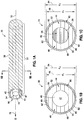
- FIGS. 1A-1C there is provided a hollow fiber 30.
- FIG. 1A is an illustration of a perspective schematic view of one of the embodiments of the hollow fiber 30 of the disclosure.
- FIG. 1B is an illustration of a cross-section taken along lines 1B-1B of the hollow fiber 30 of FIG. 1A.
- FIG. 1C is an illustration of a cross-section of a precursor fiber 31 with a fugitive polymer core portion 28 prior to conversion to the hollow fiber 30 of FIG. 1A .
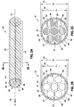
- FIG. 2A is an illustration of a perspective schematic view of another one of the embodiments of a hollow fiber 30 of the disclosure.
- FIG. 2B is an illustration of a cross-section taken along lines 2B-2B of the hollow fiber 30 of FIG. 2A.
- FIG. 2C is an illustration of a cross-section of a precursor fiber 31 with a fugitive polymer core portion 28 prior to conversion to the hollow fiber 30 of FIG. 2A .
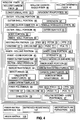
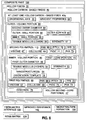
- FIG. 3 is an illustration of a block diagram of one of the embodiments of the hollow fiber 30 of the disclosure.
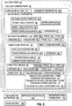
- FIG. 4 is an illustration of a block diagram of another one of the embodiments of a hollow fiber 30 of the disclosure.
- the term "fiber” as used herein means both fibers of finite length, such as known staple fibers, as well as substantially continuous structures, such as filaments, unless otherwise indicated.
- the hollow fiber 30 has a longitudinal axis 32 that runs a length 33 of the hollow fiber 30.
- the hollow fiber 30 is preferably continuous and has a hollow portion structure 34 (see FIG. 1A ) rather than being solid.
- the hollow fiber 30 preferably has a cylindrical or tubular configuration 36 or another suitable configuration.
- the hollow fiber 30 preferably comprises a hollow carbon fiber 38 (see FIG. 4 ), a hollow carbon-based fiber 40 (see FIG. 4 ) such as a hollow graphite fiber 42 (see FIG. 4 ), or another suitable hollow fiber.
- the hollow fiber 30 comprises an inner-volume portion 44, preferably in the form of an inner core portion 46 (see also FIG. 4 ).
- the inner-volume portion 44 comprises a first outer diameter (d 1 ) 48.
- the first outer diameter (d 1 ) 48 may preferably range in length from about 2 micrometers to about 50 micrometers; may more preferably range from about 4 micrometers to about 10 micrometers; or may most preferably range about 4 micrometers to about 7 micrometers, or may have another suitable length.
- the inner-volume portion 44 further comprises an inner body portion 50 and an outer-wall portion 52 surrounding the inner body portion 50.
- the inner-volume portion 44 further comprises a first-core portion 45 (see also FIGS. 3-4 ).
- the first-core portion 45 comprises one or more nanostructure(s) 54 or a plurality of nanostructures 54 (see FIGS. 3-4 ).
- the nanostructure(s) 54 comprise carbon nanostructure(s) 56 or nanotube(s) 58.
- Other examples of nanostructures(s) are carbon nanotube(s) 60, halloysite nanotube(s) 62, boron nitride nanotube(s) 64, or another suitable nanostructure that promotes templating of a precursor polymer.
- the nanostructure(s) 54 are nanotube(s) 58, and preferably, the nanostructure(s) 54 are carbon nanotube(s) 60.
- the nanotube(s) 58, such as carbon nanotube(s) 60, that are used may comprise single-wall, double-wall, or multi-wall structures.
- Single-wall carbon nanotubes may be made from any known method, such as by gas-phase synthesis from high-temperature, high-pressure carbon monoxide, catalytic vapor deposition using carbon-containing feedstocks and metal catalyst particles, laser ablation, arc method, or any other method for synthesizing single-wall carbon nanotubes.
- the single-wall carbon nanotubes obtained from synthesis are generally in the form of single-wall-carbon-nanotube powder, which may also be supplied as a dispersion or suspension in a liquid, such as dimethyl acetamide (DMAc), dimethyl formamide (DMF), or another suitable fluid.
- the inner-volume portion 44 may comprise a percentage of nanostructure content, such as nanotube content, preferably ranging in an amount of from about 0.01% by weight to about 10% by weight; more preferably ranging in an amount of from about 0.01% by weight to about 5% by weight; and most preferably ranging in an amount of from about 0.1% by weight to about 1% by weight.
- the nanotubes 58 are preferably substantially aligned along the longitudinal axis 32 (see FIG. 1A ) of the hollow fiber 30.
- the first-core portion 45 of the inner-volume portion 44 further comprises one or more first polymer(s) 66.
- the first polymer 66 comprises a polymer such as polyacrylonitrile (PAN) 68, pitch 70, polyphenylene sulfide (PPS) 72, viscose 67, cellulose 69, polyvinylidene chloride (PVDC) 71, polyvinyl alcohol (PVA) 73, or combinations thereof.
- PAN polyacrylonitrile
- PPS polyphenylene sulfide
- PVDC polyvinylidene chloride
- PVA polyvinyl alcohol
- polyacrylonitrile (PAN) polymer includes polymers comprising at least about 85% by weight acrylonitrile units (generally known in the art as acrylic or polyacrylonitrile polymers). This term as used herein also includes polymers which have less that 85% by weight acrylonitrile units. Such polymers include modacrylic polymers, generally defined as polymers comprising from about 35% by weight to about 85% by weight acrylonitrile units and typically copolymerized with vinyl chloride or vinylidene chloride. Preferably, the polyacrylonitrile polymer has at least 85% by weight polyacrylonitrile units.
- Other polymers known in the art to be suitable precursors for carbon and graphite fibers such as polyvinyl alcohol, aromatic polyamides, or poly(acetylenes), may be suitable, if capable of extrusion by melt spinning.
- melt-processable polyacrylonitriles are described in U.S. Pat. Nos. 5,602,222 , 5,618,901 and 5,902,530 ..
- Such polymers are commercially available, for example, from BP Chemicals Inc., as BAREX acrylic polymers (BAREX is a registered trademark of BP Chemicals Inc. of Cleveland, Ohio), and the like.
- melt-processable/spinnable PANs are particularly preferred because they are excellent precursors for the formation of carbon fibers.
- melt-processable PANs exhibit adequate heat resistance, with a melting point of approximately 185°C (degrees Celsius).
- Polyacrylonitrile fibers also exhibit good tensile strength and resilience.
- polyacrylonitrile fibers are especially advantageous in those embodiments employing dissolution as a means of extraction, because polyacrylonitrile possesses superior water and chemical resistance, thus allowing a wide range of solvents to be employed in the dissolution of the fugitive component.
- pitch is the name for any of a number of highly viscous liquids which appear solid at room temperature and include a mixture of predominantly aromatic and alkyl-substituted aromatic hydrocarbons.
- Pitch may be made from petroleum products or plants. Petroleum-derived pitch is also called bitumen, while pitch produced from plants is also known as resin.
- the pitch polymer comprises a mesophase pitch. When heated, pitch materials form an isotropic mass. As heating continues, spherical bodies begin to form. The spherical bodies are of an anisotropic liquid-crystalline nature.
- mesophase is the intermediate phase or liquid-crystalline region between the isotropic pitch and the semi-coke obtainable at higher temperatures.
- Mesophase pitch suitable for certain embodiments disclosed herein may be extracted from natural pitch.
- mesophase pitch may be solvent-extracted from isotropic pitch containing mesogens as described in U.S. Pat. No. 5,032,250 .
- U.S. Pat. Nos. 4,277,324 and 4,208,267 also describe processes for obtaining mesophase pitch by treating isotropic pitch.
- An isotropic pitch comprises molecules which are not aligned in optically ordered crystals and mesogens are mesophase-forming materials or mesophase precursors.
- polyphenylene sulfide may be substituted for the melt-spinnable PAN.
- Polyphenylene sulfide (PPS) is considered as an important high-temperature polymer because it exhibits a number of desirable properties.
- polyphenylene sulfides desirably exhibit resistance to heat, acids and alkalis, to mildew, to bleaches, aging, sunlight, and abrasion.
- the continuous carbon nanofiber comprises a long-chain synthetic polysulfide in which at least 85% to about 99% of the sulfide linkages are attached directly to two aromatic rings.
- a polyarylene sulfide resin composition may be substituted for the PAN.
- the resin composition may include at least 70 mole % of p-phenylene sulfide units (e.g., 70 mole % to 100 mole % or 80 mole % to 90 mole %).
- the balance or remaining 30 mole % may include any combination of an alkyl or an alkoxy group having from 1 to 12 carbon atoms, a phenyl group and a nitro group.
- the resin compositions may also include metal hydroxides and/or iron oxides. Suitable resin compositions are provided in U.S. Pat. No. 5,021,497 ..
- the nanostructure(s) 54 act as an orientation template 74 (see FIG. 3 ) for orientation or orienting of the one or more first polymer(s) 66, and in particular, the polymer chains of the first polymer(s) 66, in a direction 76 (see FIG. 3 ) that is parallel or substantially parallel to a direction (D) 78 (see FIG. 1A ) of the longitudinal axis 32 of the hollow fiber 30.
- the carbon nanotube(s) 60 may act as orientation templates for the one or more first polymer(s) 66 in the direction 76 that is parallel or substantially parallel to the longitudinal axis 32 of the hollow fiber 30.
- the nanostructure(s) 54, in particular the nanotube(s) 58, for instance carbon nanotube(s) may act as nucleating agents for polymer crystallization.
- the templating or orientation effect of the nanostructure(s) 54 in particular the nanotube(s) 58, for instance carbon nanotube(s), enables an ordered, crystalline microstructure as compared to known fibers that may have an amorphous microstructure in the core portion of the fiber.
- the first-core portion 45 of the inner-volume portion 44 further comprises one or more hollow second-core portion(s) 47.
- the first-core portion 45 is in contact with and completely encompasses, the one or more hollow second-core portion(s) 47.
- the hollow second-core portion 47 comprises a single hollow second-core portion configuration 49 extending through a length 33 (see FIG. 1A ) of the hollow fiber 30.
- the single hollow second-core portion configuration 49 extends through a center portion 51 of the hollow fiber 30.
- the hollow second-core portion 47 comprises a plurality of hollow second-core portions configuration 53 where each hollow second-core portion 47 extends through a length 33 (see FIG. 2A ) of the hollow fiber 30.
- the plurality of hollow second-core portions configuration 53 is in the form of an islands-in-a-sea configuration 55 (see FIG. 2A ).
- the one or more hollow second-core portion(s) 47 may preferably be formed when a fugitive polymer 29 is extracted or disappears during conversion of the precursor fiber 31 (see FIGS. 1C and 2C ) to the hollow fiber 30.
- fugitive polymer refers to compounds that may be extracted out of a multi-component fiber or precursor fiber after spinning, but at any one of several points of the fiber-making process.
- multi-component fibers are formed of two or more polymeric materials which have been extruded together to provide continuous contiguous polymer segments which extend down the length of the hollow fiber.
- FIG. 1C is an illustration of a cross-section of a precursor fiber 31 with a fugitive polymer core portion 28 prior to conversion to the hollow fiber 30 of FIG. 1A .
- FIG. 2C is an illustration of a cross-section of a precursor fiber 31 with a fugitive polymer core portion 28 prior to conversion to the hollow fiber 30 of FIG. 2A .
- the fugitive polymer 29 comprises a plurality of islands 57
- the first polymer 66 comprises a sea 59.
- the first polymer 66 may comprise a plurality of solid islands and the fugitive polymer 29 comprises a sea.
- the diameter of the islands 57 of the fugitive polymer 29 may range in length from about 20 nanometers to 1000 nanometers, or 50 nanometers to 950 nanometers, or 100 nanometers to 900 nanometers, or 250 nanometers to 600 nanometers, or may have another suitable length.
- the weight ratio of the first polymer 66, such as PAN, to the fugitive polymer 29 may range from about 20/80 to about 80/20.
- the islands-in-the-sea configuration 55 may also be characterized by the island/sea ratio.
- the island/sea ratio may also range from 20/80 to 80/20. In one preferred embodiment, the island/sea ratio ranges from 40/60 to 50/50.
- the fugitive polymer may comprise water-soluble polymers, such as but not limited to, polyvinyl alcohol, polyethylene oxide, polyacrylamide, polylactic acid, or water-soluble copolyester resins, copolymers, terpolymers, and mixtures thereof, or organic-solvent-extractable polymers, such as polystyrene or polyester.
- the fugitive polymer may be extracted from the multi-component fiber using a suitable solvent after spinning but before heat treatment to carbonize the polymer, such as the PAN, component.
- the fugitive component may comprise a polymer which decomposes upon heat treatment, such as that generally associated with the carbonization of PAN polymers. The decomposition products may then be extracted or removed from the multi-component fibers generally through diffusion through the non-fugitive materials.
- the first polymer 66 and second polymer 100 such as melt-spinnable PAN, and the fugitive polymer 29 are chosen so as to be mutually incompatible.
- the various components preferably have the appropriate solubility characteristics, such that the fugitive polymer is soluble in solvent (if removed using a solvent-extraction process), while the insoluble polymer is preferably capable of withstanding the extraction of the fugitive polymer without detriment.
- a balance of adhesion/incompatibility between the components of the composite fiber is considered highly beneficial.
- the components advantageously adhere sufficiently to each other to allow the pre-extracted multi-component fiber to be subjected to conventional textile processing such as winding, twisting, weaving, knitting or carding without any appreciable separation of the components, if so desired.
- the polymers are preferably sufficiently incompatible so that adhesion between the components is sufficiently weak, so as to provide ready dissolution during the extraction process.
- the hollow fiber 30 further comprises an outer-volume portion 80, preferably in the form of an outer shell portion 82 (see FIG. 4 ).
- the outer-volume portion 80 comprises a second outer diameter (d 2 ) 84.
- the second outer diameter (d 2 ) 84 of the outer-volume portion 80 of the hollow fiber 30 may be varied to fit a desired need or to provide desired properties.
- the second outer diameter (d 2 ) 84 may preferably range in length from about 2 micrometers to about 50 micrometers; may more preferably range from about 5 micrometers to about 10 micrometers; or may most preferably range about 5 micrometers to about 7 micrometers, or may have another suitable length.
- the outer-volume portion 80 of the hollow fiber 30 may further comprise an inner-wall portion 86, and an outer-wall portion 88 having an outer surface 90.
- the outer-volume portion 80 may further comprise a body portion 92 formed between the inner-wall portion 86 and the outer-wall portion 88.
- the outer-volume portion 80 is in contact with and completely encompasses the inner-volume portion 44.
- the outer-volume portion 80 cylindrically encompasses the inner-volume portion 44.
- the inner-volume portion 44 has at least one of a tensile modulus 94 and a strength 95 that are higher than at least one of a tensile modulus 96 and a strength 97 of the outer-volume portion 80, and in particular, at the outer surface 90 of the outer-volume portion 80.
- the hollow fiber 30 has gradient properties 98 (see FIG. 4 ) that vary from the tensile modulus 94 and/or the strength 95, that are preferably higher in the inner-volume portion 44, to the tensile modulus 96 and/or the strength 97, that are preferably lower at the outer-volume portion 80, and in particular, at the outer surface 90 of the outer-volume portion 80.
- This results in the hollow fiber 30 having, as shown in FIG. 4 , an improved resistance 102 to microfracture formation 104 at a fiber-matrix interface 106 between the outer surface 90 of the outer-volume portion 80 of the hollow fiber 30 and a resin matrix 108 cured or coupled to the hollow fiber 30.
- the outer-volume portion 80 of the hollow fiber 30 further comprises one or more second polymer(s) 110.
- the second polymer 110 comprises a polymer such as polyacrylonitrile (PAN) 68, pitch 70, polyphenylene sulfide (PPS) 72, viscose 67, cellulose 69, polyvinylidene chloride (PVDC) 71, polyvinyl alcohol (PVA) 73, or comninations thereof.
- the first polymer 66 and the second polymer 110 each comprise the identical or same polymer.
- the first polymer 66 and the second polymer 110 each comprise a different polymer from the same, e.g., identical, polymer or polymer family.
- FIG. 5 there is provided a hollow fiber 30, preferably in the form of a hollow carbon fiber 38.
- FIG. 5 is an illustration of a block diagram of another one of the embodiments of the hollow fiber 30 in the form of the hollow carbon fiber 38.
- the hollow fiber 30, such as the hollow carbon fiber 38 comprises an inner core portion 46.
- the inner core portion 46 comprises a first-core portion 45 having a first outer diameter (d 1 ) 48, a plurality of carbon nanotube(s) 60, and a plurality of first polymer(s) 66.
- the carbon nanotube(s) 60 act as an orientation template 74 for orientation of the first polymer(s) 66 in a direction 76 parallel or substantially parallel to the longitudinal axis 32 of the hollow fiber 30, such as the hollow carbon fiber 38. Further, the carbon nanotube(s) 60 may act as orientation templates of the first polymer(s) 66 in the direction 76 parallel or substantially parallel to the longitudinal axis 32 of the hollow fiber 30, such as the hollow carbon fiber 38.
- the inner core portion 46 further comprises one or more hollow second-core portions 47.
- the hollow second-core portion 47 may comprise a single hollow second-core portion configuration 49 extending through a length 33 (see FIG. 1A ) of the hollow fiber 30.
- the single hollow second-core portion configuration 49 extends through a center portion 51 of the hollow fiber 30.
- the hollow second-core portion 47 comprises a plurality of hollow second-core portions configuration 53, where each hollow second-core portion 47 extends through a length 33 (see FIG. 2A ) of the hollow fiber 30.
- the plurality of hollow second-core portions configuration 53 is in the form of an islands-in-a-sea configuration 55.
- the first-core portion 45 is in contact with and completely encompasses, the one or more hollow second-core portions 47.
- the hollow fiber 30, such as the hollow carbon fiber 38 further comprises an outer shell portion 82 having a second outer diameter (d 2 ) 84 (see FIG. 1B ) and having one or more second polymer(s) 110.
- the outer shell portion 82 is in contact with and completely, and preferably cylindrically, encompasses the inner core portion 46.
- the inner core portion 46 preferably has at least one of a tensile modulus 94 and a strength 95 that are higher than at least one of a tensile modulus 96 and a strength 97 of the outer shell portion 82, and in particular, at the outer surface 90 of the outer-wall portion 88 of the outer shell portion 82.
- the first polymer 66 and the second polymer 110 may each comprise the identical or same polymer. Alternatively, the first polymer 66 and the second polymer 110 may each comprise a different polymer from a same polymer family.
- the first polymer 66 and the second polymer 110 each comprise a polymer, as discussed above, such as polyacrylonitrile (PAN) 68, pitch 70, polyphenylene sulfide (PPS) 72, viscose 67, cellulose 69, polyvinylidene chloride (PVDC) 71, polyvinyl alcohol (PVA) 73, or combinations thereof. As shown in FIG.
- the hollow fiber 30, such as the hollow carbon fiber 38 preferably has gradient properties 98 that vary from the tensile modulus 94 and/or the strength 95, that are higher in the inner core portion 46, to a tensile modulus 96 and/or the strength 97, that are lower at an outer shell portion 82, and in particular, at an outer surface 90 of the outer-wall portion 88 of the outer shell portion 82.
- This preferably results in the hollow fiber 30, such as the hollow carbon fiber 38, having an improved resistance 102 to microfracture formation 104 at a fiber-matrix interface 106 between the hollow fiber 30, such as the hollow carbon fiber 38, and a resin matrix 108.
- FIG. 6 is an illustration of a block diagram of one of the embodiments of the composite part 100 comprising a plurality of hollow fibers 30, preferably in the form of a plurality of hollow carbon-based fibers 40. At least one of the hollow carbon-based fibers 40a comprises an inner-volume portion 44 having a first outer diameter (d 1 ) 48 (see FIG. 1B ) and having a plurality of nanostructure(s) 54 and one or more first polymer(s) 66.
- the nanostructure(s) 54 act as an orientation template 74 for orientation of the one or more first polymer(s) 66 in a direction 76 parallel or substantially parallel to the longitudinal axis 32 of the at least one hollow carbon-based fiber 40a. Further, the nanostructure(s) 54 may act as orientation templates for the one or more first polymer(s) 66 in the direction 76 parallel or substantially parallel to the longitudinal axis 32 of the at least one hollow carbon-based fiber 40a. As shown in FIG. 6 , the at least one hollow carbon-based fiber 40a further comprises an outer-volume portion 80 having a second outer diameter (d 2 ) 84 (see FIG. 1B ) and having one or more second polymer(s) 110.
- the outer-volume portion 80 is in contact with and completely encompasses the inner-volume portion 44.
- the inner-volume portion 44 has at least one of a tensile modulus 94 and a strength 95that are higher than at least one of a tensile modulus 96 and a strength 97 of the outer-volume portion 80, and in particular, at the outer surface 90 of the outer-wall portion 88 of the outer-volume portion 80.
- the composite part 100 further comprises a resin matrix 108 cured to the plurality of hollow carbon-based fibers 40 and cured to the at least one hollow carbon-based fiber 40a.
- the first polymer 66 and the second polymer 110 each comprise the identical or same polymer. Alternatively, the first polymer 66 and the second polymer 110 each comprise a different polymer from the same polymer family. The first polymer 66 and the second polymer 110 each comprise a polymer, as discussed above and shown in FIG.
- the nanostructure(s) 54 comprise nanotube(s) 58, such as carbon nanotube(s) 60, halloysite nanotube(s) 62 or boron nitride nanotube(s) 64, that promotes templating of a precursor polymer.
- nanotube(s) 58 such as carbon nanotube(s) 60, halloysite nanotube(s) 62 or boron nitride nanotube(s) 64, that promotes templating of a precursor polymer.
- the at least one hollow carbon-based fiber 40a preferably has gradient properties 98 that vary from the tensile modulus 94 and/or the strength 95 in the inner-volume portion 44 to the tensile modulus 96 and/or the strength 97 at the outer-volume portion 80, and in particular, at the outer surface 90 of the outer-wall portion 88 of the outer-volume portion 80. This preferably results in the at least one hollow carbon-based fiber 40a having an improved resistance 102 to microfracture formation 104 at a fiber-matrix interface 106 between the at least one hollow carbon-based fiber 40a and a resin matrix 108.
- FIG. 7 is an illustration of a perspective view of an exemplary aircraft 10 that may incorporate a composite part 100 (see also FIG. 5 ) having one or more advantageous embodiments of the hollow fiber 30 (see FIGS. 1A-6 ) as disclosed herein.
- the aircraft 10 comprises a fuselage or body 12, a nose 14, a cockpit 16, wings 18 operatively coupled to the fuselage or body 12, one or more propulsion units 20, a tail vertical stabilizer 22, and one or more tail horizontal stabilizers 24.
- composite parts such as composite part 100 for the wing 18 having one or more hollow fibers 30 (see FIGS. 1A-6 ), may also be employed in other types of aircraft.
- teachings of the disclosed embodiments may be applied to other passenger aircraft, cargo aircraft, military aircraft, rotorcraft, and other types of aircraft or aerial vehicles, as well as aerospace vehicles, satellites, space launch vehicles, rockets, and other aerospace vehicles. It may also be appreciated that embodiments of the assemblies, methods, and systems in accordance with the disclosure may be utilized in other transport vehicles, such as boats and other watercraft, trains, automobiles, trucks, buses, or other suitable transport vehicles. It may further be appreciated that embodiments of the assemblies, methods, and systems in accordance with the disclosure may be used in various composite structures having one or more of the hollow fibers 30.
- FIGS. 8-10 there is provided a method 200 of making a hollow fiber 30 (see FIGS. 1A-6 and 8 ) having improved resistance 102 (see FIG. 8 ) to microfracture formation 104 (see FIG. 8 ) at a fiber-matrix interface 106 (see FIG. 8).
- FIG. 8 is an illustration of a schematic diagram of an exemplary embodiment of the method 200 of the disclosure.
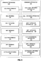
- FIG. 9 is an illustration of a block diagram of exemplary embodiments of spinning techniques 120 and spinning apparatuses 122 that may be used in embodiments of the disclosed method 200 of the disclosure.
- FIG. 10 is an illustration of a flow diagram of an exemplary embodiment of the method 200 of the disclosure.
- the method 200 comprises step 202 of mixing in a first solvent 112 (see FIG. 8 ) a plurality of nanostructure(s) 54 (see FIG. 8 ), one or more first polymer(s) 66 (see FIG. 8 ), and a fugitive polymer 29 which is dissociable from the nanostructure(s) 54 and the one or more first polymer(s) 66, in order to form an inner-volume portion mixture 114 (see FIG. 8 ).
- the nanostructure(s) 54 comprise, as shown in FIG.
- nanotube(s) 58 such as carbon nanotube(s) 60, halloysite nanotube(s) 62 or boron nitride nanotube(s) 64, that promotes templating of a precursor polymer.
- the fugitive polymer 29 may comprises a polymer such as polymethylmethacrylate, polyvinyl alcohol, polyethylene oxide, polyacrylamide, polylactic acid, polystyrene, or water-soluble copolyester resins, copolymers, terpolymers, or mixtures thereof, or another suitable polymer.
- the nanostructure(s) 54, such as carbon nanotube(s) 60 may be in an amount of from about 0.01% to about 10% by weight of the inner-volume portion mixture 114.
- the nanostructures, such as the carbon nanotubes may be dispersed within the inner-volume portion mixture 114 by mechanical and/or chemical means (e.g., dispersants or surfactants).
- the method 200 further comprises step 204 of mixing in a second solvent 116 (see FIG. 8 ) one or more second polymer(s) 110 (see FIG. 8 ) in order to form an outer-volume portion mixture 118 (see FIG. 8 ).
- the first polymer 66 and the second polymer 110 each comprise the identical or same polymer.
- the first polymer 66 and the second polymer 110 each comprise a different polymer from the same polymer family.
- the first polymer 66 and the second polymer 110 each comprise a polymer, as discussed above and as shown in FIG.
- PAN polyacrylonitrile
- PPS polyphenylene sulfide
- VDC polyvinylidene chloride
- PVA polyvinyl alcohol
- the first solvent 112 and the second solvent 116 may each comprise an identical or same solvent. Alternatively, the first solvent 112 and the second solvent 116 may each comprise a different solvent.
- the first solvent 112 and the second solvent 116 may each comprise a solvent such as dimethylacetamide (DMAc), dimethylformamide (DMF), dimethylsulfoxide (DMSO), dimethyl sulfone (DMSO 2 ), ethylene carbonate, propylene carbonate (PPC), chloroacetonitrile, dimethyl phosphate (DDVP), acetic anhydride (Ac 2 O), or another suitable solvent.
- DMAc dimethylacetamide
- DMF dimethylformamide
- DMSO dimethylsulfoxide
- DMSO 2 dimethyl sulfone
- PPC propylene carbonate
- chloroacetonitrile dimethyl phosphate
- DDVP dimethyl phosphate
- Ac 2 O acetic anhydride
- the method 200 further comprises step 206 of spinning the inner-volume portion mixture 114 and the outer-volume portion mixture 118 and extracting the fugitive polymer 29 from the inner-volume portion mixture 114 in order to form a hollow precursor fiber 31.
- Spinning may comprise a known spinning technique 120 (see FIG. 9 ) using a known spinning apparatus 122 (see FIG. 9 ).
- FIG. 9 shows a known spinning technique 120 (see FIG. 9 ) using a known spinning apparatus 122 (see FIG. 9 ).
- the spinning technique 120 may comprise solution spinning 124 using a solution-spinning apparatus 126, gel spinning 128 using a gel-spinning apparatus 130, wet spinning 136 using a wet-spinning apparatus 138, electrospinning 140 using an electrospinning apparatus 142, dry spinning 144 using a dry-spinning apparatus 146, and combinations thereof, or another suitable spinning process. Also, melt spinning 132 using a melt-spinning apparatus 134 and extrusion spinning 148 using an extrusion-spinning apparatus 150 are known.
- the method 200 further comprises step 208 of heating the precursor fiber 31 to oxidize 152 the precursor fiber 31 and to change a molecular-bond structure 154 of the precursor fiber 31.
- the precursor fibers 31 may be subjected to carbonization comprising the heating of the oxidized precursor fibers 31 to a temperature ranging from about 600 degrees Celsius to about 3000 degrees Celsius.
- the inner-volume portion mixture 114 and the outer-volume portion mixture 118 may be extruded and fed into a spin-pack assembly capable of producing fibers comprising nanoscale dimensions and substantially aligning the nanostructures, such as the carbon nanotubes, with the first polymer 66, such as PAN.
- the fugitive polymer 29 which is dissociable from the melt-spinnable PAN may be provided to a separate extruder.
- the inner-volume portion mixture 114 and the outer-volume portion mixture 118 and the fugitive polymer 29 may be separately extruded and fed into a spin-pack assembly capable of producing multi-component fibers comprising nanoscale dimensions in an islands-in-the-sea configuration 55 and substantially aligning the nanostructures, such as the carbon nanotubes, with the first polymer 66, such as the PAN polymer.
- various methods include extracting the fugitive polymer 29 from the multi-component fibers to form PAN fibers.
- Such fibers may be oxidized by sufficiently heating the PAN fibers. Oxidation may involve heating the PAN fibers to around 300 degrees Celsius.
- the PAN polymer changes from a ladder structure to a stable ring structure as understood by those skilled in the art.
- the oxidized PAN fibers may be subjected to a carbonization.
- Carbonization may comprise heating of the oxidized fibers to a temperature ranging from about 600 degrees Celsius to about 3000 degrees Celsius.
- Extrusion parameters for making multi-component continuous-filament fibers comprising a PAN polymer/carbon nanotube mixture and the fugitive polymer to provide a fiber having nanoscale dimensions according to embodiments described herein may vary depending on the properties desired.
- at least two polymers e.g., PAN/carbon nanotube mixture and the fugitive polymer
- the polymers follow separate paths to the fiber spinneret and are combined in a spinneret hole.
- the spinneret is configured so that the extrudant has the desired overall fiber cross section (e.g., round, trilobal, etc.).
- desired overall fiber cross section e.g., round, trilobal, etc.
- the method 200 further comprises step 210 of obtaining a hollow fiber 30 comprising an inner-volume portion 44 with a first outer diameter (d 1 ) 48 (see FIG. 1B ) and having a first-core portion 45 with the nanostructure(s) 54 and with the one or more first polymer(s) 66 being oriented in a direction 76 parallel to a longitudinal axis 32 of the hollow fiber 30.
- the inner-volume portion 44 further has one or more hollow second-core portions 47.
- the first-core portion 45 is in contact with and encompasses, preferably completely encompasses, the one or more hollow second-core portions 47.
- the hollow fiber 30 further comprises an outer-volume portion 80 with a second outer diameter (d 2 ) 84 (see FIG.
- the inner-volume portion 44 has at least one of a tensile modulus 94 and a strength 95, i.e., a tensile modulus and/or a strength, that are higher than at least one of a tensile modulus 96 and a strength 97, i.e., a tensile modulus and/or a strength, of the outer-volume portion 80, and in particular, of the outer surface 90 of the outer-wall portion 88 of the outer-volume portion 80.
- a tensile modulus 94 and a strength 95 i.e., a tensile modulus and/or a strength
- a strength 95 i.e., a tensile modulus and/or a strength
- the hollow fiber 30 may preferably comprise a hollow carbon fiber 38 (see FIG. 3 ), a hollow carbon-based fiber 40 (see FIG. 3 ) such as a hollow graphite fiber 42 (see FIG. 3 ), or another suitable hollow fiber.
- the method 200 further optionally comprises step 212 of curing a resin matrix 108 to a plurality of the hollow fibers 30 to form a composite part 100 (see FIGS. 6-7 ).
- the first polymer 66 and the second polymer 110 typically are selected to have melting temperatures such that the first and second polymer(s) 66, 110, respectively, may be spun at a polymer throughput that enables the spinning of the components through a common capillary at substantially the same temperature without degrading one of the components.
- the resulting thin fluid strands, or filaments may remain in a molten state for some distance before they are solidified by cooling in a surrounding fluid medium, which may be chilled and air blown through the strands.
- the filaments may be taken up on a godet or other take-up surface.
- the strands may be taken up on a godet that draws down the thin fluid streams in proportion to the speed of the take-up godet.
- Continuous-filament fiber may further be processed into staple fiber.
- staple fibers large numbers, e.g., 1,000 strands to 100,000 strands, of continuous filament may be gathered together following extrusion to form a tow for use in further processing, as is known in that art.
- the use of such tows is likewise known in continuous-filament applications, as well.
- a finish solution may optionally be applied, to aid in fiber processing, as is known in the art. Such finish solution may be chosen so as not to interfere with downstream processes such as extraction and various heat treatments.
- a heightened molecular alignment may be achieved while producing the carbon-nanotube-reinforced fibers due to the geometric constraints imposed during spinning. These constraints are preferably greater than those realized when producing larger-diameter fibers. Additionally, the spinneret of the spinning technique and spinning apparatus may be designed to allow for the tailoring of filament diameter and/or wall thickness. As such, a whole range of properties may be achieved.
- Polymer-distribution technology allowing the economical production of micro- and nano-sized fibers may use techniques similar to printed-circuit-board technology to manufacture the spin-pack components. These precise components may then be used to accurately distribute polymers in an extremely small area available in the spin pack. Such spin packs allow for the economical and practical production of micro- and nano-sized fibers. Such spin-packs may be provided by Hills, Inc. of West Melbourne, Florida.
- continuous carbon fibers with nanoscale features structures including carbon nanotubes substantially aligned therein may be produced by utilizing a spin pack having a distribution system that provides a level of precision to enable the production of nanoscale features within fiber/filament cross sections, especially nanoscale islands-in-a-sea type fibers.
- the geometrical constraints imposed by the precise distribution system of such spin packs substantially align the carbon nanotubes along a longitudinal axis of the fiber. More specifically, the geometric constraints imposed by the choice of spin pack helps cause the PAN and the carbon nanotubes to become substantially aligned within each other along the longitudinal direction of the fiber.
- PAN may be substantially oriented along the carbon nanotubes that are aligned in the longitudinal direction of the fiber throughout substantially the entire cross section of a PAN precursor having a honeycomb-like cross section.
- carbon nanotubes may be substantially aligned with substantially the entire cross section of a continuous carbon fiber with nanoscale features having a honeycomb-like cross section in the longitudinal direction of the fiber.
- the resulting carbon-nanotube-reinforced PAN hollow fibers disclosed herein may beneficially be graphitized into structural carbon fibers.
- Such carbon-nanotube-reinforced PAN fibers may include nanotube dimensions to provide improved properties.
- the PAN precursors may have the fugitive polymer, if present, removed prior to or during oxidation and carbonization to produce a hollow carbon fiber.
- the melt-spinnable PAN may be replaced with other polymers such as pitch (preferably mesophase pitch) or polyphenylene sulfide (PPS).
- pitch preferably mesophase pitch
- PPS polyphenylene sulfide
- carbon nanotubes may be blended into molten pitch at or slightly above its softening temperature. The blend is then heated to an extrusion temperature which can be about 20 degrees Celsius to about 30 degrees Celsius above the softening temperature and a pitch fiber may be extruded by melt spinning as discussed herein.
- the pitch-based fiber, having carbon nanotubes may next be oxidized and then carbonized.
- Disclosed embodiments of the hollow fiber 30 and method 200 provide a core-shell hollow fiber wherein both the inner core portion 46 and the outer shell portion 82 are made from the same polymer material, preferably, polyacrylonitrile (PAN) 68 (see FIG.4 ).
- PAN polyacrylonitrile
- a novel feature is that in the inner core portion 46, the PAN 68 contains nanostructure(s) 54 being nanotube(s) 58, such as carbon nanotube(s) 60 (see FIG. 4 ).
- the templating or orientation effect of the nanostructure(s) 54 being nanotube(s) 58, such as carbon nanotube(s) 60 (see FIG. 4 ), enable an ordered, crystalline microstructure, as compared to known fibers that may have an amorphous microstructure in the core portion of the fiber.
- disclosed embodiments of the hollow fiber 30 and method 200 provide a core-shell hollow fiber with improved strength and stiffness at a reduced weight with little or no effect on cost.
- nanostructure(s) 54 in the inner-volume portion 44 such as the inner core portion 46, aligns polymer chains of the one or more first polymer(s) 66 to create a higher stiffness in the inner-volume portion 44 and a lower stiffness at the outer surface 90 of the outer-wall portion 88 of the outer-volume portion 80 of the hollow fiber 30.
- any possible mismatch at the fiber-matrix interface 106 between the stiffness of the resin matrix 108 and the stiffness of the hollow fiber 30 is minimized or eliminated.
- Disclosed embodiments of the hollow fiber 30 and method 200 provide a core-shell nanofiber that is functionally graded and preferably has gradient properties 98 that vary from the tensile modulus 94 and/or the strength 95 in the inner-volume portion 44 to the tensile modulus 96 and/or the strength 97 in the outer-volume portion 80, and in particular, at the outer surface 90 of the outer-wall portion 88 of the outer-volume portion 80 of the hollow fiber 30.
- the fiber-matrix interface 106 properties of tensile modulus, tensile strength, stiffness, and other properties are improved at the fiber-matrix interface 106. This results in improved resistance of the hollow fiber 30 to microfracture formation 104 at the fiber-matrix interface 106 between the hollow fiber 30 and a resin matrix 108.
- Disclosed embodiments of the hollow fiber 30 and method 200 provide a functionally graded hollow carbon fiber 38 in which the outer-volume portion 80 of the hollow fiber 30 has different properties from the inner-volume portion 44 and the inner-volume portion also comprises significant areas that are continuously hollow along the length of the hollow fiber 30.
- the one or more hollow second-core portions 47 of the inner core portion 45 of the hollow fiber 30 introduces one or more hollow portions to the center of the hollow fiber 30 to reduce weight while maintaining performance.
- the hollowed portions may be localized islands or extend throughout the length of the fiber.
- Disclosed embodiments of the hollow fiber 30 and method 200 provide in one embodiment an outer shell portion 82 - first-core portion 45 - hollow second-core portion 47 configuration and in another embodiment an outer shell portion 82 islands-in-a-sea configuration 55 core portion.
- the outer shell portion 82 in both embodiments is preferably unfilled polymer.
- the first-core portion 45 may comprise one or more polymers identical or different to the polymers comprising the outer shell portion 82 and further comprises nanotubes, such as carbon nanotubes, that serve to align the polymer along the length of the hollow fiber 30 to increase mechanical properties and to form more highly graphitic structure than the shell or sheath when the hollow fiber is graphitized.
- the hollow second-core portion 47 is formed from a fugitive polymer 29 that disappears during conversion of the precursor fiber 31 to carbon to leave a hollow center.
- the islands comprise the hollow second-core portion 47 and the sea comprises the first-core portion 45 material such that, during conversion of the precursor fiber 31 to carbon, the islands disappear leaving the hollow second-core portions 47.
- a core-shell hollow fiber is produced wherein both the inner core portion and outer shell or sheath portion are made from the same basic material--e.g. polyacrylonitrile (PAN).
- PAN polyacrylonitrile
- the nanotubes act to template the PAN molecules to provide a more-graphitic structure with higher stiffness and strength than available from PAN alone. Furthermore, such templating or orientation effect of the nanotubes, such as the carbon nanotubes, enables an ordered, graphitic microstructure.
Landscapes
- Engineering & Computer Science (AREA)
- Mechanical Engineering (AREA)
- Textile Engineering (AREA)
- Chemical & Material Sciences (AREA)
- Chemical Kinetics & Catalysis (AREA)
- General Chemical & Material Sciences (AREA)
- Dispersion Chemistry (AREA)
- Organic Chemistry (AREA)
- Manufacturing & Machinery (AREA)
- Oil, Petroleum & Natural Gas (AREA)
- Inorganic Chemistry (AREA)
- Multicomponent Fibers (AREA)
- Compositions Of Macromolecular Compounds (AREA)
- Artificial Filaments (AREA)
- Inorganic Fibers (AREA)
Applications Claiming Priority (1)
| Application Number | Priority Date | Filing Date | Title |
|---|---|---|---|
| US13/316,506 US9683310B2 (en) | 2011-12-10 | 2011-12-10 | Hollow fiber with gradient properties and method of making the same |
Publications (2)
| Publication Number | Publication Date |
|---|---|
| EP2602363A1 EP2602363A1 (en) | 2013-06-12 |
| EP2602363B1 true EP2602363B1 (en) | 2019-02-13 |
Family
ID=47227668
Family Applications (1)
| Application Number | Title | Priority Date | Filing Date |
|---|---|---|---|
| EP12194048.0A Active EP2602363B1 (en) | 2011-12-10 | 2012-11-23 | Hollow fiber with gradient properties and method of making the same |
Country Status (6)
| Country | Link |
|---|---|
| US (3) | US9683310B2 (enExample) |
| EP (1) | EP2602363B1 (enExample) |
| JP (1) | JP6180105B2 (enExample) |
| CN (1) | CN103160941B (enExample) |
| BR (1) | BR102012031443B1 (enExample) |
| ES (1) | ES2726098T3 (enExample) |
Cited By (1)
| Publication number | Priority date | Publication date | Assignee | Title |
|---|---|---|---|---|
| EP4226993A4 (en) * | 2020-10-05 | 2024-10-23 | Toray Industries, Inc. | Gas separation membrane and gas separation membrane module |
Families Citing this family (11)
| Publication number | Priority date | Publication date | Assignee | Title |
|---|---|---|---|---|
| WO2015119676A2 (en) * | 2014-02-04 | 2015-08-13 | The Boeing Company | Fiber-reinforced resin composites and methods of making the same |
| US10629814B2 (en) * | 2017-02-07 | 2020-04-21 | University Of South Florida | Coaxial semiconductive organic nanofibers and electrospinning fabrication thereof |
| CN106894107B (zh) * | 2017-03-06 | 2022-03-04 | 东华大学 | 聚苯硫醚/改性埃洛石纳米管杂化复合纤维及其制备方法 |
| US10787755B2 (en) | 2017-06-05 | 2020-09-29 | The Boeing Company | Method and apparatus for manufacturing carbon fibers |
| KR102115600B1 (ko) * | 2017-07-13 | 2020-05-26 | 주식회사 엘지화학 | 구조체의 제조방법 |
| US10612163B2 (en) * | 2017-08-24 | 2020-04-07 | GM Global Technology Operations LLC | Modification of continuous carbon fibers during precursor formation for composites having enhanced moldability |
| US10941510B2 (en) | 2017-12-08 | 2021-03-09 | GM Global Technology Operations LLC | Equipment for perforated pre-impregnated reinforcement materials |
| US10533266B2 (en) * | 2018-05-11 | 2020-01-14 | The Boeing Company | Layered carbon fiber |
| CN110257937A (zh) * | 2019-06-24 | 2019-09-20 | 绍兴诚邦高新纤维科技有限公司 | 一种自卷曲复合长丝及其加工工艺 |
| US11498318B2 (en) | 2019-12-05 | 2022-11-15 | GM Global Technology Operations LLC | Class-A components comprising moldable carbon fiber |
| CN116034008A (zh) * | 2020-08-06 | 2023-04-28 | 昕诺飞控股有限公司 | 使用fdm的连续中空管打印 |
Family Cites Families (39)
| Publication number | Priority date | Publication date | Assignee | Title |
|---|---|---|---|---|
| US3677705A (en) | 1970-03-09 | 1972-07-18 | Celanese Corp | Process for the carbonization of a stabilized acrylic fibrous material |
| US4208267A (en) | 1977-07-08 | 1980-06-17 | Exxon Research & Engineering Co. | Forming optically anisotropic pitches |
| US4277324A (en) | 1979-04-13 | 1981-07-07 | Exxon Research & Engineering Co. | Treatment of pitches in carbon artifact manufacture |
| US5156831A (en) | 1986-01-21 | 1992-10-20 | Clemson University | Method for producing high strength, melt spun carbon fibers |
| US5162074A (en) | 1987-10-02 | 1992-11-10 | Basf Corporation | Method of making plural component fibers |
| US5021497A (en) | 1988-06-17 | 1991-06-04 | Ube Industries, Ltd. | Polyarylene sulfide resin composition |
| US5032250A (en) | 1988-12-22 | 1991-07-16 | Conoco Inc. | Process for isolating mesophase pitch |
| EP0421944A3 (en) | 1989-08-31 | 1992-06-17 | Tanaka Kikinzoku Kogyo K.K. | Composite carbon fibre and process for preparing same |
| US5338605A (en) | 1990-01-31 | 1994-08-16 | Ketema, Inc. | Hollow carbon fibers |
| MY131716A (en) | 1993-11-10 | 2007-08-30 | Standard Oil Co | A process for making a polymer of acrylonitrile, methacrylonitrile and olefinically unsaturated monomers |
| US5618901A (en) | 1993-11-10 | 1997-04-08 | The Standard Oil Company | Process for making a high nitrile multipolymer prepared from acrylonitrile and olefinically unsaturated monomers |
| US5700573A (en) * | 1995-04-25 | 1997-12-23 | Mccullough; Francis Patrick | Flexible biregional carbonaceous fiber, articles made from biregional carbonaceous fibers, and method of manufacture |
| DK0891433T3 (da) | 1996-03-29 | 2003-08-25 | Fibervisions L P | Polypropylenfibre og genstande fremstillet deraf |
| JPH1088430A (ja) * | 1996-09-09 | 1998-04-07 | Toray Ind Inc | 炭素繊維、炭素繊維製造用プリカーサーおよびその製造方法 |
| US5902530A (en) | 1997-12-12 | 1999-05-11 | The Standard Oil Company | Process of making high nitrile composite filaments |
| JP3940546B2 (ja) | 1999-06-07 | 2007-07-04 | 株式会社東芝 | パターン形成方法およびパターン形成材料 |
| US6743500B2 (en) | 2001-08-03 | 2004-06-01 | Hitachi Chemical Company, Ltd. | Hollow carbon fiber and production method |
| US6764628B2 (en) | 2002-03-04 | 2004-07-20 | Honeywell International Inc. | Composite material comprising oriented carbon nanotubes in a carbon matrix and process for preparing same |
| US6852410B2 (en) | 2002-07-01 | 2005-02-08 | Georgia Tech Research Corporation | Macroscopic fiber comprising single-wall carbon nanotubes and acrylonitrile-based polymer and process for making the same |
| JP2004097918A (ja) * | 2002-09-09 | 2004-04-02 | Nok Corp | ポリエーテルイミド複合中空糸膜およびその製造法 |
| WO2006137893A2 (en) | 2004-10-01 | 2006-12-28 | Board Of Regents Of The University Of Texas System | Polymer-free carbon nanotube assemblies (fibers, ropes, ribbons, films) |
| JP2006137869A (ja) | 2004-11-12 | 2006-06-01 | Nissan Motor Co Ltd | 樹脂組成物 |
| JP4892910B2 (ja) | 2005-09-29 | 2012-03-07 | 東レ株式会社 | 導電性繊維およびそれを用いてなる繊維製品 |
| EP1935480B1 (en) * | 2005-10-13 | 2013-03-27 | Asahi Kasei Chemicals Corporation | Process for producing a porous multilayered hollow-fiber membrane |
| WO2007103422A1 (en) | 2006-03-07 | 2007-09-13 | Clemson University | Mesoporous carbon fiber with a hollow interior or a convoluted surface |
| JP2010530929A (ja) | 2007-01-30 | 2010-09-16 | ジョージア テック リサーチ コーポレイション | 炭素繊維および炭素膜、ならびにそれらの作製方法 |
| US8388795B2 (en) | 2007-05-17 | 2013-03-05 | The Boeing Company | Nanotube-enhanced interlayers for composite structures |
| EP2205364A4 (en) * | 2007-10-11 | 2012-07-11 | Georgia Tech Res Inst | CARBON FIBERS AND FILMS AND MANUFACTURING METHOD THEREFOR |
| JP2009185425A (ja) | 2008-02-08 | 2009-08-20 | Shinshu Univ | 中空炭素繊維 |
| US8187700B2 (en) * | 2008-11-12 | 2012-05-29 | The Boeing Company | Continuous, carbon-nanotube-reinforced polymer precursors and carbon fibers |
| US8337730B2 (en) | 2009-01-05 | 2012-12-25 | The Boeing Company | Process of making a continuous, multicellular, hollow carbon fiber |
| US7875802B2 (en) | 2009-01-05 | 2011-01-25 | The Boeing Company | Thermoplastic-based, carbon nanotube-enhanced, high-conductivity layered wire |
| US7897876B2 (en) | 2009-01-05 | 2011-03-01 | The Boeing Company | Carbon-nanotube/graphene-platelet-enhanced, high-conductivity wire |
| US7875801B2 (en) | 2009-01-05 | 2011-01-25 | The Boeing Company | Thermoplastic-based, carbon nanotube-enhanced, high-conductivity wire |
| KR101822349B1 (ko) * | 2009-03-16 | 2018-03-08 | 보르벡크 머터리얼스 코포레이션 | 중합체 섬유 및 이로부터 제조된 물품 |
| FR2946176A1 (fr) | 2009-05-27 | 2010-12-03 | Arkema France | Fibre conductrice multicouche et son procede d'obtention par co-extrusion. |
| CN102085457B (zh) * | 2009-12-07 | 2013-01-02 | 广州美能材料科技有限公司 | 一种制备复合多层多孔中空纤维膜的方法及其装置和产品 |
| CN101768791B (zh) | 2010-02-10 | 2011-11-09 | 北京化工大学 | 一种聚丙烯腈基中空碳纤维原丝的制备方法 |
| US9096955B2 (en) * | 2011-09-30 | 2015-08-04 | Ut-Battelle, Llc | Method for the preparation of carbon fiber from polyolefin fiber precursor, and carbon fibers made thereby |
-
2011
- 2011-12-10 US US13/316,506 patent/US9683310B2/en active Active
-
2012
- 2012-11-23 ES ES12194048T patent/ES2726098T3/es active Active
- 2012-11-23 EP EP12194048.0A patent/EP2602363B1/en active Active
- 2012-12-07 JP JP2012268032A patent/JP6180105B2/ja active Active
- 2012-12-10 BR BR102012031443A patent/BR102012031443B1/pt active IP Right Grant
- 2012-12-10 CN CN201210530067.7A patent/CN103160941B/zh active Active
-
2017
- 2017-02-23 US US15/441,174 patent/US10253433B2/en active Active
-
2019
- 2019-04-08 US US16/377,257 patent/US10774447B2/en active Active
Non-Patent Citations (1)
| Title |
|---|
| None * |
Cited By (1)
| Publication number | Priority date | Publication date | Assignee | Title |
|---|---|---|---|---|
| EP4226993A4 (en) * | 2020-10-05 | 2024-10-23 | Toray Industries, Inc. | Gas separation membrane and gas separation membrane module |
Also Published As
| Publication number | Publication date |
|---|---|
| US9683310B2 (en) | 2017-06-20 |
| US20130149523A1 (en) | 2013-06-13 |
| CN103160941B (zh) | 2017-04-05 |
| BR102012031443A2 (pt) | 2013-11-12 |
| US20170159210A1 (en) | 2017-06-08 |
| US10253433B2 (en) | 2019-04-09 |
| JP6180105B2 (ja) | 2017-08-16 |
| ES2726098T3 (es) | 2019-10-01 |
| CN103160941A (zh) | 2013-06-19 |
| US10774447B2 (en) | 2020-09-15 |
| JP2013122105A (ja) | 2013-06-20 |
| BR102012031443B1 (pt) | 2020-02-04 |
| US20190233973A1 (en) | 2019-08-01 |
| EP2602363A1 (en) | 2013-06-12 |
Similar Documents
| Publication | Publication Date | Title |
|---|---|---|
| US10774447B2 (en) | Method of making hollow fiber with gradient properties | |
| JP2013122105A5 (enExample) | ||
| US8435628B2 (en) | Continuous, carbon-nanotube-reinforced polymer precursors and carbon fibers | |
| US10246798B2 (en) | Method of making fiber with gradient properties | |
| Buckley et al. | Carbon-carbon materials and composites | |
| Gulgunje et al. | Low-density and high-modulus carbon fibers from polyacrylonitrile with honeycomb structure | |
| RU2504604C2 (ru) | Изделия из чистых углеродных нанотрубок, изготовленные из растворов суперкислот, и способы их получения | |
| CN101768791B (zh) | 一种聚丙烯腈基中空碳纤维原丝的制备方法 | |
| CN110093677B (zh) | 一种聚丙烯腈纤维、聚丙烯腈基碳纤维及其制备方法 | |
| US5338605A (en) | Hollow carbon fibers | |
| US20110285049A1 (en) | Carbon nanotube (cnt)-enhanced precursor for carbon fiber production and method of making a cnt-enhanced continuous lignin fiber | |
| US10301750B2 (en) | Continuous, hollow polymer precursors and carbon fibers produced therefrom | |
| Love-Baker et al. | Analysis of the turbostratic structures in PAN-based carbon fibers with wide-angle x-ray diffraction | |
| Newcomb et al. | The properties of carbon fibers | |
| Shaikh et al. | Progress in carbon fiber and its polypropylene-and polyethylene-based composites | |
| EP1954383A1 (en) | A braid-reinforced composite hollow fiber membrane | |
| Acatay | Carbon fibers | |
| CN101250769B (zh) | 高性能的碳纳米管/pbo复合纤维的电纺丝制备方法 | |
| JPS616313A (ja) | ピツチ系炭素繊維の製造方法 | |
| Wen | Novel continuous carbon and ceramic nanofibers and nanocomposites | |
| CN117448977A (zh) | 一种低回潮尼龙纤维及其面料、制备方法 |
Legal Events
| Date | Code | Title | Description |
|---|---|---|---|
| PUAI | Public reference made under article 153(3) epc to a published international application that has entered the european phase |
Free format text: ORIGINAL CODE: 0009012 |
|
| AK | Designated contracting states |
Kind code of ref document: A1 Designated state(s): AL AT BE BG CH CY CZ DE DK EE ES FI FR GB GR HR HU IE IS IT LI LT LU LV MC MK MT NL NO PL PT RO RS SE SI SK SM TR |
|
| AX | Request for extension of the european patent |
Extension state: BA ME |
|
| 17P | Request for examination filed |
Effective date: 20131211 |
|
| RBV | Designated contracting states (corrected) |
Designated state(s): AL AT BE BG CH CY CZ DE DK EE ES FI FR GB GR HR HU IE IS IT LI LT LU LV MC MK MT NL NO PL PT RO RS SE SI SK SM TR |
|
| 17Q | First examination report despatched |
Effective date: 20150618 |
|
| STAA | Information on the status of an ep patent application or granted ep patent |
Free format text: STATUS: EXAMINATION IS IN PROGRESS |
|
| GRAP | Despatch of communication of intention to grant a patent |
Free format text: ORIGINAL CODE: EPIDOSNIGR1 |
|
| STAA | Information on the status of an ep patent application or granted ep patent |
Free format text: STATUS: GRANT OF PATENT IS INTENDED |
|
| INTG | Intention to grant announced |
Effective date: 20180228 |
|
| GRAJ | Information related to disapproval of communication of intention to grant by the applicant or resumption of examination proceedings by the epo deleted |
Free format text: ORIGINAL CODE: EPIDOSDIGR1 |
|
| STAA | Information on the status of an ep patent application or granted ep patent |
Free format text: STATUS: EXAMINATION IS IN PROGRESS |
|
| GRAP | Despatch of communication of intention to grant a patent |
Free format text: ORIGINAL CODE: EPIDOSNIGR1 |
|
| STAA | Information on the status of an ep patent application or granted ep patent |
Free format text: STATUS: GRANT OF PATENT IS INTENDED |
|
| INTC | Intention to grant announced (deleted) | ||
| INTG | Intention to grant announced |
Effective date: 20180815 |
|
| GRAS | Grant fee paid |
Free format text: ORIGINAL CODE: EPIDOSNIGR3 |
|
| GRAA | (expected) grant |
Free format text: ORIGINAL CODE: 0009210 |
|
| STAA | Information on the status of an ep patent application or granted ep patent |
Free format text: STATUS: THE PATENT HAS BEEN GRANTED |
|
| AK | Designated contracting states |
Kind code of ref document: B1 Designated state(s): AL AT BE BG CH CY CZ DE DK EE ES FI FR GB GR HR HU IE IS IT LI LT LU LV MC MK MT NL NO PL PT RO RS SE SI SK SM TR |
|
| REG | Reference to a national code |
Ref country code: GB Ref legal event code: FG4D |
|
| REG | Reference to a national code |
Ref country code: CH Ref legal event code: EP Ref country code: AT Ref legal event code: REF Ref document number: 1096296 Country of ref document: AT Kind code of ref document: T Effective date: 20190215 |
|
| REG | Reference to a national code |
Ref country code: IE Ref legal event code: FG4D |
|
| REG | Reference to a national code |
Ref country code: DE Ref legal event code: R096 Ref document number: 602012056607 Country of ref document: DE |
|
| REG | Reference to a national code |
Ref country code: LT Ref legal event code: MG4D |
|
| REG | Reference to a national code |
Ref country code: NL Ref legal event code: MP Effective date: 20190213 |
|
| PG25 | Lapsed in a contracting state [announced via postgrant information from national office to epo] |
Ref country code: NO Free format text: LAPSE BECAUSE OF FAILURE TO SUBMIT A TRANSLATION OF THE DESCRIPTION OR TO PAY THE FEE WITHIN THE PRESCRIBED TIME-LIMIT Effective date: 20190513 Ref country code: LT Free format text: LAPSE BECAUSE OF FAILURE TO SUBMIT A TRANSLATION OF THE DESCRIPTION OR TO PAY THE FEE WITHIN THE PRESCRIBED TIME-LIMIT Effective date: 20190213 Ref country code: FI Free format text: LAPSE BECAUSE OF FAILURE TO SUBMIT A TRANSLATION OF THE DESCRIPTION OR TO PAY THE FEE WITHIN THE PRESCRIBED TIME-LIMIT Effective date: 20190213 Ref country code: PT Free format text: LAPSE BECAUSE OF FAILURE TO SUBMIT A TRANSLATION OF THE DESCRIPTION OR TO PAY THE FEE WITHIN THE PRESCRIBED TIME-LIMIT Effective date: 20190613 Ref country code: SE Free format text: LAPSE BECAUSE OF FAILURE TO SUBMIT A TRANSLATION OF THE DESCRIPTION OR TO PAY THE FEE WITHIN THE PRESCRIBED TIME-LIMIT Effective date: 20190213 Ref country code: NL Free format text: LAPSE BECAUSE OF FAILURE TO SUBMIT A TRANSLATION OF THE DESCRIPTION OR TO PAY THE FEE WITHIN THE PRESCRIBED TIME-LIMIT Effective date: 20190213 |
|
| PG25 | Lapsed in a contracting state [announced via postgrant information from national office to epo] |
Ref country code: LV Free format text: LAPSE BECAUSE OF FAILURE TO SUBMIT A TRANSLATION OF THE DESCRIPTION OR TO PAY THE FEE WITHIN THE PRESCRIBED TIME-LIMIT Effective date: 20190213 Ref country code: RS Free format text: LAPSE BECAUSE OF FAILURE TO SUBMIT A TRANSLATION OF THE DESCRIPTION OR TO PAY THE FEE WITHIN THE PRESCRIBED TIME-LIMIT Effective date: 20190213 Ref country code: GR Free format text: LAPSE BECAUSE OF FAILURE TO SUBMIT A TRANSLATION OF THE DESCRIPTION OR TO PAY THE FEE WITHIN THE PRESCRIBED TIME-LIMIT Effective date: 20190514 Ref country code: HR Free format text: LAPSE BECAUSE OF FAILURE TO SUBMIT A TRANSLATION OF THE DESCRIPTION OR TO PAY THE FEE WITHIN THE PRESCRIBED TIME-LIMIT Effective date: 20190213 Ref country code: BG Free format text: LAPSE BECAUSE OF FAILURE TO SUBMIT A TRANSLATION OF THE DESCRIPTION OR TO PAY THE FEE WITHIN THE PRESCRIBED TIME-LIMIT Effective date: 20190513 Ref country code: IS Free format text: LAPSE BECAUSE OF FAILURE TO SUBMIT A TRANSLATION OF THE DESCRIPTION OR TO PAY THE FEE WITHIN THE PRESCRIBED TIME-LIMIT Effective date: 20190613 |
|
| REG | Reference to a national code |
Ref country code: AT Ref legal event code: MK05 Ref document number: 1096296 Country of ref document: AT Kind code of ref document: T Effective date: 20190213 |
|
| REG | Reference to a national code |
Ref country code: ES Ref legal event code: FG2A Ref document number: 2726098 Country of ref document: ES Kind code of ref document: T3 Effective date: 20191001 |
|
| PG25 | Lapsed in a contracting state [announced via postgrant information from national office to epo] |
Ref country code: DK Free format text: LAPSE BECAUSE OF FAILURE TO SUBMIT A TRANSLATION OF THE DESCRIPTION OR TO PAY THE FEE WITHIN THE PRESCRIBED TIME-LIMIT Effective date: 20190213 Ref country code: EE Free format text: LAPSE BECAUSE OF FAILURE TO SUBMIT A TRANSLATION OF THE DESCRIPTION OR TO PAY THE FEE WITHIN THE PRESCRIBED TIME-LIMIT Effective date: 20190213 Ref country code: CZ Free format text: LAPSE BECAUSE OF FAILURE TO SUBMIT A TRANSLATION OF THE DESCRIPTION OR TO PAY THE FEE WITHIN THE PRESCRIBED TIME-LIMIT Effective date: 20190213 Ref country code: RO Free format text: LAPSE BECAUSE OF FAILURE TO SUBMIT A TRANSLATION OF THE DESCRIPTION OR TO PAY THE FEE WITHIN THE PRESCRIBED TIME-LIMIT Effective date: 20190213 Ref country code: SK Free format text: LAPSE BECAUSE OF FAILURE TO SUBMIT A TRANSLATION OF THE DESCRIPTION OR TO PAY THE FEE WITHIN THE PRESCRIBED TIME-LIMIT Effective date: 20190213 Ref country code: AL Free format text: LAPSE BECAUSE OF FAILURE TO SUBMIT A TRANSLATION OF THE DESCRIPTION OR TO PAY THE FEE WITHIN THE PRESCRIBED TIME-LIMIT Effective date: 20190213 |
|
| REG | Reference to a national code |
Ref country code: DE Ref legal event code: R097 Ref document number: 602012056607 Country of ref document: DE |
|
| PG25 | Lapsed in a contracting state [announced via postgrant information from national office to epo] |
Ref country code: PL Free format text: LAPSE BECAUSE OF FAILURE TO SUBMIT A TRANSLATION OF THE DESCRIPTION OR TO PAY THE FEE WITHIN THE PRESCRIBED TIME-LIMIT Effective date: 20190213 Ref country code: SM Free format text: LAPSE BECAUSE OF FAILURE TO SUBMIT A TRANSLATION OF THE DESCRIPTION OR TO PAY THE FEE WITHIN THE PRESCRIBED TIME-LIMIT Effective date: 20190213 |
|
| PLBE | No opposition filed within time limit |
Free format text: ORIGINAL CODE: 0009261 |
|
| STAA | Information on the status of an ep patent application or granted ep patent |
Free format text: STATUS: NO OPPOSITION FILED WITHIN TIME LIMIT |
|
| PG25 | Lapsed in a contracting state [announced via postgrant information from national office to epo] |
Ref country code: AT Free format text: LAPSE BECAUSE OF FAILURE TO SUBMIT A TRANSLATION OF THE DESCRIPTION OR TO PAY THE FEE WITHIN THE PRESCRIBED TIME-LIMIT Effective date: 20190213 |
|
| 26N | No opposition filed |
Effective date: 20191114 |
|
| PG25 | Lapsed in a contracting state [announced via postgrant information from national office to epo] |
Ref country code: SI Free format text: LAPSE BECAUSE OF FAILURE TO SUBMIT A TRANSLATION OF THE DESCRIPTION OR TO PAY THE FEE WITHIN THE PRESCRIBED TIME-LIMIT Effective date: 20190213 |
|
| PG25 | Lapsed in a contracting state [announced via postgrant information from national office to epo] |
Ref country code: TR Free format text: LAPSE BECAUSE OF FAILURE TO SUBMIT A TRANSLATION OF THE DESCRIPTION OR TO PAY THE FEE WITHIN THE PRESCRIBED TIME-LIMIT Effective date: 20190213 |
|
| REG | Reference to a national code |
Ref country code: CH Ref legal event code: PL |
|
| PG25 | Lapsed in a contracting state [announced via postgrant information from national office to epo] |
Ref country code: LU Free format text: LAPSE BECAUSE OF NON-PAYMENT OF DUE FEES Effective date: 20191123 Ref country code: MC Free format text: LAPSE BECAUSE OF FAILURE TO SUBMIT A TRANSLATION OF THE DESCRIPTION OR TO PAY THE FEE WITHIN THE PRESCRIBED TIME-LIMIT Effective date: 20190213 Ref country code: CH Free format text: LAPSE BECAUSE OF NON-PAYMENT OF DUE FEES Effective date: 20191130 Ref country code: LI Free format text: LAPSE BECAUSE OF NON-PAYMENT OF DUE FEES Effective date: 20191130 |
|
| REG | Reference to a national code |
Ref country code: BE Ref legal event code: MM Effective date: 20191130 |
|
| PG25 | Lapsed in a contracting state [announced via postgrant information from national office to epo] |
Ref country code: IE Free format text: LAPSE BECAUSE OF NON-PAYMENT OF DUE FEES Effective date: 20191123 |
|
| PG25 | Lapsed in a contracting state [announced via postgrant information from national office to epo] |
Ref country code: BE Free format text: LAPSE BECAUSE OF NON-PAYMENT OF DUE FEES Effective date: 20191130 |
|
| PG25 | Lapsed in a contracting state [announced via postgrant information from national office to epo] |
Ref country code: CY Free format text: LAPSE BECAUSE OF FAILURE TO SUBMIT A TRANSLATION OF THE DESCRIPTION OR TO PAY THE FEE WITHIN THE PRESCRIBED TIME-LIMIT Effective date: 20190213 |
|
| PG25 | Lapsed in a contracting state [announced via postgrant information from national office to epo] |
Ref country code: MT Free format text: LAPSE BECAUSE OF FAILURE TO SUBMIT A TRANSLATION OF THE DESCRIPTION OR TO PAY THE FEE WITHIN THE PRESCRIBED TIME-LIMIT Effective date: 20190213 Ref country code: HU Free format text: LAPSE BECAUSE OF FAILURE TO SUBMIT A TRANSLATION OF THE DESCRIPTION OR TO PAY THE FEE WITHIN THE PRESCRIBED TIME-LIMIT; INVALID AB INITIO Effective date: 20121123 |
|
| PG25 | Lapsed in a contracting state [announced via postgrant information from national office to epo] |
Ref country code: MK Free format text: LAPSE BECAUSE OF FAILURE TO SUBMIT A TRANSLATION OF THE DESCRIPTION OR TO PAY THE FEE WITHIN THE PRESCRIBED TIME-LIMIT Effective date: 20190213 |
|
| P01 | Opt-out of the competence of the unified patent court (upc) registered |
Effective date: 20230516 |
|
| PGFP | Annual fee paid to national office [announced via postgrant information from national office to epo] |
Ref country code: DE Payment date: 20241127 Year of fee payment: 13 |
|
| PGFP | Annual fee paid to national office [announced via postgrant information from national office to epo] |
Ref country code: GB Payment date: 20241127 Year of fee payment: 13 |
|
| PGFP | Annual fee paid to national office [announced via postgrant information from national office to epo] |
Ref country code: FR Payment date: 20241128 Year of fee payment: 13 |
|
| PGFP | Annual fee paid to national office [announced via postgrant information from national office to epo] |
Ref country code: IT Payment date: 20241122 Year of fee payment: 13 Ref country code: ES Payment date: 20241202 Year of fee payment: 13 |