EP2601878A2 - Geschirrspülmaschine mit automatischer Drehrichtungsumkehr des Sprüharms - Google Patents
Geschirrspülmaschine mit automatischer Drehrichtungsumkehr des Sprüharms Download PDFInfo
- Publication number
- EP2601878A2 EP2601878A2 EP12401245.1A EP12401245A EP2601878A2 EP 2601878 A2 EP2601878 A2 EP 2601878A2 EP 12401245 A EP12401245 A EP 12401245A EP 2601878 A2 EP2601878 A2 EP 2601878A2
- Authority
- EP
- European Patent Office
- Prior art keywords
- spray arm
- distribution chamber
- spray
- dishwasher according
- nozzles
- Prior art date
- Legal status (The legal status is an assumption and is not a legal conclusion. Google has not performed a legal analysis and makes no representation as to the accuracy of the status listed.)
- Granted
Links
- 239000007921 spray Substances 0.000 title claims abstract description 131
- 238000005406 washing Methods 0.000 claims description 16
- 230000015572 biosynthetic process Effects 0.000 claims description 2
- 238000005507 spraying Methods 0.000 abstract description 3
- 239000012530 fluid Substances 0.000 description 9
- 239000008237 rinsing water Substances 0.000 description 6
- 238000010276 construction Methods 0.000 description 4
- 239000007788 liquid Substances 0.000 description 4
- XLYOFNOQVPJJNP-UHFFFAOYSA-N water Substances O XLYOFNOQVPJJNP-UHFFFAOYSA-N 0.000 description 4
- 238000004140 cleaning Methods 0.000 description 2
- 238000004851 dishwashing Methods 0.000 description 2
- 238000011010 flushing procedure Methods 0.000 description 2
- 230000005484 gravity Effects 0.000 description 2
- 230000004913 activation Effects 0.000 description 1
- 238000005096 rolling process Methods 0.000 description 1
Images
Classifications
-
- A—HUMAN NECESSITIES
- A47—FURNITURE; DOMESTIC ARTICLES OR APPLIANCES; COFFEE MILLS; SPICE MILLS; SUCTION CLEANERS IN GENERAL
- A47L—DOMESTIC WASHING OR CLEANING; SUCTION CLEANERS IN GENERAL
- A47L15/00—Washing or rinsing machines for crockery or tableware
- A47L15/42—Details
- A47L15/4278—Nozzles
- A47L15/4282—Arrangements to change or modify spray pattern or direction
-
- A—HUMAN NECESSITIES
- A47—FURNITURE; DOMESTIC ARTICLES OR APPLIANCES; COFFEE MILLS; SPICE MILLS; SUCTION CLEANERS IN GENERAL
- A47L—DOMESTIC WASHING OR CLEANING; SUCTION CLEANERS IN GENERAL
- A47L15/00—Washing or rinsing machines for crockery or tableware
- A47L15/14—Washing or rinsing machines for crockery or tableware with stationary crockery baskets and spraying devices within the cleaning chamber
- A47L15/18—Washing or rinsing machines for crockery or tableware with stationary crockery baskets and spraying devices within the cleaning chamber with movably-mounted spraying devices
- A47L15/22—Rotary spraying devices
- A47L15/23—Rotary spraying devices moved by means of the sprays
Definitions
- the invention relates to a dishwasher having a washing compartment and a spray system provided in the washing compartment, which has a rotatably mounted spray arm, wherein the spray arm drive nozzles, which drive nozzles serve a rotary drive of the spray arm in the left direction on the one hand and in the right direction on the other.
- Dishwashers of the type mentioned are known from the prior art per se. A separate documentary proof is therefore not required at this point.
- Generic dishwashers have a Spülbottich, which in turn provides a Spülraum.
- the washing compartment is accessible via an opening in the washing tub, which opening can be closed in a fluid-tight manner by means of a door pivotably arranged on the washing tub.
- the washing compartment of the dishwasher serves to receive items to be cleaned. This is applied as part of a designated Spülprogrammablaufs by means of rinsing liquid, the so-called wash liquor.
- a dishwashing machine has a spray system provided in the washing compartment for loading items to be cleaned with washing liquor.
- a spray system typically has at least one rotatably mounted spray arm.
- several such spray arms are provided, and depending on the design of the dishwasher two or three spray arms are common practice.
- Each spray arm is connected to a supply line for rinsing water.
- rinsing liquor passes through this supply line to the spray arm, via which the rinsing liquor is discharged in the direction of the items to be cleaned.
- the rinsing liquor emitted by the spray arm collects in the washing compartment and is guided in an open flow circuit for a renewed spraying of the dishes.
- a circulation pump is used, which continuously circulates the rinsing liquor during a proper program implementation.
- not all the spray arms are used at the same time in a designated program sequence. It is rather a feed to different sections of the program different spray arms with rinsing liquor instead, for the purpose of water saving preferably not more than two spray arms are operated simultaneously with rinsing water.
- a water switch cooperating with the circulation pump is regularly used, wherein a feeding of the spray arms takes place as a function of the position of the water distributor.
- the DE 3816408 A1 discloses a dishwasher in which drive nozzles are provided for a rotary drive of the spray arm in the left direction and drive nozzles for a rotary drive of the spray arm in the right direction.
- "Left direction” means a drive of the spray arm in the counterclockwise direction and "right direction” in the opposite direction, ie in the clockwise direction.
- the respective drive nozzles are connected to two separate channels in the spray arm, which are supplied via two separate supply lines with rinsing liquid.
- the supply lines are connected to separate output connections of the water separator.
- the DE 103 55 343 B3 discloses a dishwashing machine in which a spray arm has two groups of nozzles. These are in fluid communication with a distribution chamber provided by the spray arm. When used as intended, rinse liquor flows into the distribution chamber of the spray arm, from where one or the other nozzle group is operated with rinsing liquor. The feeding of the nozzle groups with rinsing liquor takes place purely by chance via a ball present in the distribution chamber. When loading the spray arm with rinsing water, this ball is spent independently of control and completely randomly in a position in which either one nozzle group or the other nozzle group is released or locked. A targeted feeding of one or the other nozzle group with rinsing liquor is not possible.
- the object of the invention to further develop a dishwasher of the type mentioned in that an improved coverage of the washing compartment with rinse liquor is achieved with the aim of improved Spülgutgraphy at the same time simplified, inexpensive and robust construction.
- the invention proposes a dishwasher of the type mentioned, which is characterized in that the spray arm has a distribution chamber, with which the drive nozzles fluidly connected are or can be connected, and a movably disposed within the distribution chamber control, which alternately releases either the drive nozzles for a rotary drive of the spray arm in the left direction or the drive nozzles for a rotary drive of the spray arm in the right direction.
- the dishwasher according to the invention has a spray arm, which is equipped with a distribution chamber and a control.
- the distribution chamber is thus arranged within the spray arm and is supplied with rinsing liquid via only one supply line.
- the control is movably disposed within the distribution chamber of the spray arm. Depending on its positioning within the distribution chamber, there are alternately free either the drive nozzles for a rotary drive of the spray arm in the left direction or the drive nozzles for a rotary drive of the spray arm in the right direction.
- the embodiment of the invention provides an improvement here, as a result of a reversal of the direction of rotation of the spray arm with respect to the items to be cleaned a beam direction change, a beam shape change as well as a change in the Strahlauf Economicswinkel causes, so that different Sprühstrahlcharaktizingen are reached. As a result, a better cleaning result can be achieved.
- the recorded by the distribution chamber control allows in contrast to the embodiment of the DE 103 55 343 B3 a targeted, namely alternately closing the drive nozzles for a left-hand rotation of the spray arm on the one hand and a clockwise rotation of the spray arm on the other.
- no random loading of the corresponding drive nozzles with rinsing liquor in contrast to the prior art no random loading of the corresponding drive nozzles with rinsing liquor.
- the control is according to a further feature of the invention, a ball.
- This serves as a closure means, wherein it closes the fluidic connection between the distribution chamber and the corresponding drive nozzles in the closed position. If the ball is not in its closed position, the fluidic connection between the corresponding drive nozzles and the distribution chamber of the spray arm is released.
- the distribution chamber provides an annular space according to another feature of the invention.
- the distribution chamber of circular cross-section is equipped with a mandrel, preferably extending in the vertical direction of the axis of rotation of the spray arm.
- the ball is positively constrained within the annulus and is free to move around on the annular path provided by the annulus about the mandrel formed centrally in the distribution chamber.
- movable elements are not required for the closure and the activation of the fluidic connections to the drive nozzles. This ensures a comparatively simple and robust construction of the spray arm.
- the advance arrangement of the annulus around the axis of rotation of the spray arm avoids imbalance of the spray arm, which could limit the stability and longevity of the system.
- the spray arm has two wings, each extending from the distribution chamber.
- Each wing provides a main channel and at least one secondary channel, preferably each wing provides a main channel and a first secondary channel and a second secondary channel.
- the two first side channels of the wings and the two second side channels of the wings preferably each form a continuous secondary channel.
- Each of the secondary channels is connected to at least one drive nozzle.
- each of the secondary channels, in particular each of the first and second sub-channels exactly one drive nozzle, which is arranged in particular at its distal end.
- the main channel is connected to a plurality of spray nozzles.
- rinsing liquor is introduced into the washing compartment of the dishwasher in the direction of the items to be cleaned.
- the secondary channels meanwhile serve to feed the drive nozzles for the purpose of rotating the spray arm.
- a feed of a secondary channel causes a rotational movement of the spray arm in the left direction
- a feed of the other secondary channel leads to a rotational movement of the spray arm in the right direction.
- the position of the control within the distribution chamber i. In this case, the ball within the annular space determines which secondary channel is charged with flushing solution in the charging case or which secondary channel is fluidically decoupled from the distribution chamber.
- the main channel of both wings and the spray nozzles connected thereto are always, i. irrespective of the position of the control element, and thus in particular irrespective of the direction of rotation of the spray arm determined thereby, is supplied with rinsing liquor.
- a rotatably mounted spray arm of the dishwasher comprises a distribution chamber and two vanes each extending from the distribution chamber, each wing having a main duct connected to a plurality of spray nozzles and at least one side duct via which the drive nozzles are fluidically connected to the distribution chamber; the spray arm further includes a control member movably disposed within the distribution chamber, which alternately releases either the drive nozzles for a rotary drive of the spray arm in the left direction or the drive nozzles for a rotary drive of the spray arm in the right direction, wherein the spray nozzles, to which a main channel is connected independently are released from the positioning of the control.
- the distribution chamber provides, as described above, an annular space in which the ball-shaped control element is forcibly guided.
- the annulus provided by the distribution chamber has a bottom surface which is formed divided into two sections.
- the two sections on a respective slope, which in run in the opposite direction. Due to this gradient of the two sections, which are formed in the opposite direction, the sections merge into one another with the respective formation of a step.
- an overflow opening also called channel opening
- the steps provided by the bottom surface of the annulus between the two bottom surface portions are radially offset from the two oppositely formed overflow openings arranged.
- the serving as a control ball abuts one of the two stages of the annular space floor.
- the ball When loading the distribution chamber with rinsing fluid, the ball is lifted above this stage, as a result of which it is guided into the overflow opening assigned to this stage. It thus comes to a closure of this overflow opening, whereby the associated secondary channel is fluidically decoupled from the distribution chamber.
- the other secondary channel is fluidically connected to the distribution chamber, so that it can flow into this wash liquor.
- the ball As soon as the feed of the spray arm ends with wash liquor, the ball is no longer held in the overflow opening and falls out of this following the gravity. Since the step associated with this overflow opening is radially offset from the overflow opening, the ball falls onto the next section of the floor surface, where it rolls down the slope of this section until the next step is reached. At this stage, the ball remains until a renewed loading of the spray arm with rinsing liquor.
- the construction according to the invention thus results in a result in constantly changing drive direction with respect to the spray arm.
- Each new loading of the spray arm with rinse liquor changes its direction of rotation.
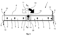
- FIG. 1 can be seen in schematic plan view from above a spray arm 1 according to the invention.
- a spray arm 1 is part of an otherwise not shown spray system of a dishwasher, also not shown otherwise.
- a dishwasher has a Spülbottich, which in turn provides a dishwasher.
- the washing compartment serves to receive items to be cleaned.
- a spray system is provided, which serves the delivery of rinsing liquid, the so-called rinsing liquor.
- Such a spraying system also includes a spray arm 1, which is arranged rotatably within the washing compartment of the dishwasher, as it is in FIG FIG. 1 is shown.
- a spray arm 1 is arranged rotatably within the washing compartment of the dishwasher, as it is in FIG FIG. 1 is shown.
- several such spray arms 1 are provided, which in the height direction of the Rinsing space are arranged one above the other and can be charged independently with rinsing liquor.
- the spray arm 1 embodied according to the invention has the first wing 2 and a second wing 3, which extend from a distribution chamber 14.
- the distribution chamber 14 is provided on the upper side with a connection opening 26. It is used for connection to a supply line not shown in the figures, via which, in the intended use case, a loading of the spray arm 1 with rinsing liquor.
- the two wings 2 and 3 each have a main channel 4 and two secondary channels 6 and 7.
- each wing 2 and 3 of the respective main channel 4 and the respective secondary channels 6 and 7 are fluidically connected to the distribution chamber 14.
- the secondary channels 6 and 7 have at their opposite end of the distribution chamber 14 via drive nozzles 8 and 9, wherein the first secondary channel, the drive nozzles 9 and the second secondary channel 7, the drive nozzles 8 are assigned.
- the rinsing liquor When loading the first secondary channel 6 with rinsing liquor, the rinsing liquor reaches the drive nozzles 9, from which the rinsing liquor emerge in the direction of the arrow 10 shown by dashed lines.
- the spray arm 1 mounted so as to be rotatable about the rotation axis 22 is set in a twisting motion, in the direction of the arrow 11 to the left, d. H. in a counterclockwise left turn.
- the main channel 4 has spray nozzles 5.
- the spray arm 1 When feeding the spray arm 1 with rinse liquor, it passes via the distribution chamber 14 into the main channel 4 and from there to the spray nozzles 5, via which the rinse liquor is dispensed onto washware arranged in the dishwasher rinse compartment.
- the spray arm 1 When used as intended, the spray arm 1 is charged with rinsing liquor. Rinse liquor is introduced into the main channel 4 for delivery via the spray nozzles 5. Furthermore, rinsing liquor is introduced into either the first sub-channel 6 or the second sub-channel 7, so that there is also an escape of rinsing water from the drive nozzles 8 or 9. As a result of this charging takes place with simultaneous delivery of rinsing fluid through the spray nozzles 5 either a left twisting movement of the spray arm 1 in the direction of arrow 11 or aqueverloomterrorism the spray arm 1 in the direction of arrow 13th
- This cooperates either with the channel opening 16 or with the channel opening 18, wherein the channel opening 16, the fluidic connection between the distribution chamber 14 and the first sub-channel 6 and the channel opening 18, the fluidic connection between the distribution chamber 14 and the second sub-channel 7 is formed.
- each channel opening 16 or 18 distribution chamber side has a chamfer, which is designed to match the ball radius of the ball 15.
- This chamfer 17 therefore represents a ball seat, which forms a seal sealed for rinse tank when ball 15 is received.
- the ball 15 can thus be made a closure of either the channel opening 16 or the channel opening 18, wherein in the closed state of the channel opening 16 is a feed of the second secondary channel 7 with rinsing and in the closed state of the channel opening 18, a feed of the first secondary channel 6 with rinsing ,
- the distribution chamber 14 has the connection opening 26 opposite a bottom surface 20. From this bottom surface 20 rises in the direction of the axis of rotation 22, a mandrel 19. To this mandrel 19 around the ball 15 can move freely in the direction of arrow 21. Thus, an annular space is provided by the distribution chamber 14, wherein the ball 15 can move on the bottom surface 20 of the distribution chamber 14 rolling within this annulus.
- the bottom surface 20 of the distribution chamber 14 is formed into two sections 23 and 24 divided.
- each of the two sections 23 and 24 is formed inclined, ie equipped with gradient, with the slope on the one hand, starting from the axis of rotation 22 in the direction of the adjoining the respective section 23 and 24 main channel 4 and on the other hand starting from the one channel opening 16th or 18 to the opposite channel opening 18 and 16, respectively.
- the section 23 on a slope, which, starting from the axis of rotation 22 with respect to the plane of the drawing FIG. 8 to extends right and simultaneously, starting from the channel opening 16 in the direction of the channel opening 18, which is particularly apparent from the representation of the FIGS. 6 and 7 results.
- the slope of the portion 24 is formed in the reverse manner and extends on the one hand by the channel opening 18 in the direction of the channel opening 16 and on the other hand by the rotation axis 22 with respect to the plane of the drawing FIG. 8 to the left.
- this section gradient results between the two sections 23 and 24 each have a step 25, which may also be referred to as a stop.
- the sections 23 and 24 are formed in their geometric dimensions such that the formed between the two sections 23 and 24 stages 25 at a radial angle to the axis of rotation 22 are stationary, as can be seen in particular from the illustration FIGS. 8 and 9 results.
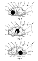
- FIG. 2 indicates an operating situation, which takes place according to a loading of the spray arm 1 with rinsing liquor.
- the ball 15 is pressed into the ball seat of the channel opening 16, wherein it is held in this position due to the inflowing into the distribution chamber 14 rinse. Since the ball 15 closes the channel opening 16, the rinsing liquor flowing into the distribution chamber 14 enters the main channel 4 and the second secondary channel 7. As a result, flushing fluid is emitted via the spray nozzles 5 to a clockwise rotation in the direction of the arrow 13 (cf. FIG. 1 ), since in the second sub-channel 7, a feed of the drive nozzles 8 with rinsing liquor in correspondence of the arrow 12 (see. FIG. 1 ) takes place.
- the holding force exerted by the rinsing liquor on the ball 15 is eliminated.
- the ball 15 disengages from the channel opening 16 and, following gravity, rolls on the section 23 of the bottom surface 20 in the direction of the slope defined by the section 23 (cf. FIG. 8 ).
- the ball 15 comes to lie in front of the channel opening 18 in front of the formed between the two sections 23 and 24 stage 25.
- this level 25 can also be referred to as a stop.
- the ball 15 is due to the geometric configuration of the stage 15 is not centered in front of the channel opening 18, but slightly off-center offset.
- the ball 15 is lifted through the step 25 as a result of the inflowing rinsing fluid and due to the pressure exerted by the rinsing fluid, the ball 15 in the channel opening 18th towed. There is a closure of the channel opening 18 and the rinsing fluid flowing into the distribution chamber 14 now no longer enters the second secondary channel 7 but rather into the first secondary channel 6.
- the ball 15 Upon renewed pressure drop within the distribution chamber 14, the ball 15 falls out of the channel opening 18 back out. However, since the step 25 is slightly offset from the channel opening 18, the ball 15 does not fall back on the section 23 but rather follows the slope provided by the section 24 to the opposite step 25 between the two sections 23 and 24, which step 25 from the representation after the FIGS. 8 and 9 results.
Abstract
Description
- Die Erfindung betrifft eine Geschirrspülmaschine mit einem Spülraum und einem im Spülraum vorgesehenen Sprühsystem, das einen drehbar gelagerten Sprüharm aufweist, wobei der Sprüharm Antriebsdüsen aufweist, welche Antriebsdüsen einem Drehantrieb des Sprüharms in Linksrichtung einerseits sowie in Rechtsrichtung andererseits dienen.
- Geschirrspülmaschinen der eingangs genannten Art sind aus dem Stand der Technik an sich bekannt. Eines gesonderten druckschriftlichen Nachweises bedarf es an dieser Stelle deshalb nicht.
- Gattungsgemäße Geschirrspülmaschinen verfügen über einen Spülbottich, der seinerseits einen Spülraum bereitstellt. Der Spülraum ist über eine Öffnung im Spülbottich zugänglich, welche Öffnung mittels einer verschwenkbar am Spülbottich angeordneten Tür fluiddicht verschließbar ist.
- Im bestimmungsgemäßen Verwendungsfall dient der Spülraum der Geschirrspülmaschine der Aufnahme von zu reinigendem Spülgut. Dieses wird im Rahmen eines bestimmungsgemäßen Spülprogrammablaufs mittels Spülflüssigkeit, der sogenannten Spülflotte beaufschlagt.
- Zur Beaufschlagung von zu reinigendem Spülgut mit Spülflotte verfügt eine Geschirrspülmaschine über ein im Spülraum vorgesehenes Sprühsystem. Ein solches System verfügt typischerweise über wenigstens einen drehbar gelagerten Sprüharm. In der Regel sind mehrere solcher Sprüharme vorgesehen, wobei je nach Ausgestaltung der Geschirrspülmaschine zwei oder drei Sprüharme gängige Praxis sind.
- Eine jeder Sprüharm ist an eine Zuleitung für Spülflotte angeschlossen. Über diese Zuleitung gelangt im Betriebsfall Spülflotte zum Sprüharm, über welchen die Spülflotte in Richtung auf das zu reinigende Spülgut abgegeben wird. Die vom Sprüharm abgegebene Spülflotte sammelt sich im Spülraum und wird für eine erneute Besprühung des Spülguts in einem offenen Strömungskreislauf geführt. Zu diesem Zweck kommt eine Umwälzpumpe zum Einsatz, die die Spülflotte während einer bestimmungsgemäßen Programmdurchführung stetig umwälzt.
- Typischerweise kommen bei einer Geschirrspülmaschine der eingangs genannten Art nicht alle Sprüharme gleichzeitig bei einem bestimmungsgemäßen Programmablauf zum Einsatz. Es findet vielmehr zu unterschiedlichen Programmabschnitten eine Beschickung unterschiedlicher Sprüharme mit Spülflotte statt, wobei zum Zwecke der Wassereinsparung bevorzugterweise nicht mehr als zwei Sprüharme gleichzeitig mit Spülflotte bedient werden. Zur Beschickung unterschiedlicher Sprüharme mit Spülflotte kommt regelmäßig eine mit der Umwälzpumpe zusammenwirkende Wasserweiche zum Einsatz, wobei eine Beschickung der Sprüharme in Abhängigkeit der Stellung der Wasserweiche erfolgt.
- Zum Zwecke des Drehantriebes des Sprüharms verfügt dieser über Antriebsdüsen. Die
DE 3816408 A1 offenbart eine Geschirrspülmaschine, bei der Antriebsdüsen für einen Drehantrieb des Sprüharms in Linksrichtung sowie Antriebsdüsen für einen Drehantrieb des Sprüharms in Rechtsrichtung vorgesehen sind. "Linksrichtung" meint dabei einen Antrieb des Sprüharms entgegen des Uhrzeigersinns und "Rechtsrichtung" in entgegengesetzter Richtung, d. h. in Richtung des Uhrzeigersinns. Die jeweiligen Antriebsdüsen sind dabei mit zwei voneinander getrennten Kanälen im Sprüharm verbunden, welche über zwei getrennte Zuführleitungen mit Spülflüssigkeit versorgt werden. Die Zuführleitungen sind an getrennte Ausgangsanschlüsse der Wasserweiche angeschlossen. - Die
DE 103 55 343 B3 offenbart eine Geschirrspülmaschine, bei der ein Sprüharm über zwei Gruppen von Düsen verfügt. Diese stehen in strömungstechnischer Verbindung mit einer vom Sprüharm bereitgestellten Verteilkammer. Im bestimmungsgemäßen Verwendungsfall strömt Spülflotte in die Verteilkammer des Sprüharms ein, von wo aus die eine oder die andere Düsengruppe mit Spülflotte bedient wird. Dabei erfolgt die Beschickung der Düsengruppen mit Spülflotte rein zufällig über eine in der Verteilkammer vorhandenen Kugel. Bei einer Beschickung des Sprüharms mit Spülflotte wird diese Kugel steuerungsunabhängig und völlig zufällig in eine Position verbracht, in der entweder die eine Düsengruppe oder die andere Düsengruppe freigegeben bzw. gesperrt ist. Eine zielgerichtete Beschickung der einen oder der anderen Düsengruppe mit Spülflotte ist nicht möglich. - Es ist ausgehend vom Vorbeschriebenen die Aufgabe der Erfindung, eine Geschirrspülmaschine der eingangs genannten Art dahingehend weiterzuentwickeln, dass eine verbesserte Abdeckung des Spülraums mit Spülflotte mit dem Ziel einer verbesserten Spülgutreinigung bei gleichzeitig vereinfachtem,preiswertem und robustem Aufbau erreicht ist.
- Zur Lösung dieser Aufgabe wird mit der Erfindung eine Geschirrspülmaschine der eingangs genannten Art vorgeschlagen, die sich auszeichnet dadurch dass der Sprüharm eine Verteilkammer aufweist, mit der die Antriebsdüsen strömungstechnisch verbunden sind oder verbunden werden können, sowie ein beweglich innerhalb der Verteilkammer angeordnetes Steuerelement, welches abwechselnd entweder die Antriebsdüsen für einen Drehantrieb des Sprüharms in Linksrichtung oder die Antriebsdüsen für einen Drehantrieb des Sprüharms in Rechtsrichtung freigibt.
- Die Geschirrspülmaschine nach der Erfindung verfügt über einen Sprüharm, der mit einer Verteilkammer und einem Steuerelement ausgerüstet ist. Die Verteilkammer ist somit innerhalb des Sprüharms angeordnet und wird über lediglich eine Zuführleitung mit Spülflüssigkeit beschickt. Das Steuerelement ist beweglich innerhalb der Verteilkammer des Sprüharms angeordnet. Es gibt je nach seiner Positionierung innerhalb der Verteilkammer abwechselnd entweder die Antriebsdüsen für einen Drehantrieb des Sprüharms in Linksrichtung oder die Antriebsdüsen für einen Drehantrieb des Sprüharms in Rechtsrichtung frei. In vorteilhafter Weise kommt es so mit einer jeden Neubeschickung des Sprüharms mit Spülflotte zu einer Drehrichtungsumkehr. Hat also in einem vorangegangenen Programmabschnitt eine Verdrehbewegung des Sprüharms beispielsweise in Linksrichtung stattgefunden, so wird nach einer Beendigung dieses Programmabschnittes und anschließender Neubeschickung des Sprüharms mit Spülflotte eine Verdrehbewegung des Sprüharms in Rechtsrichtung durchgeführt werden. Die erfindungsgemäße Ausgestaltung erbringt mithin bei jeder Neubeschickung des Sprüharms mit Spülflotte einen sich umkehrenden, d. h. einen sich in seiner Drehrichtung abwechselnden Richtungssinn.
- Aufgrund der alternierenden Drehrichtung des Sprüharms ergeben sich hinsichtlich des vom Spülraum der Geschirrspülmaschine aufgenommenen Spülgutes von Drehrichtungsumkehr zu Drehrichtungsumkehr unterschiedliche Spülflottenstrahlrichtungen, Auftreffwinkel und/oder Spülflottenstrahlformen. Aufgrund dessen stellt sich eine optimierte Abdeckung des Spülraums durch unterschiedliche Sprühbilder ein, was im Ergebnis in vorteilhafterweise zu einem verbesserten Reinigungsresultat führt.
- Bei Spülmaschinen der eingangs genannten Art kommen typischerweise eine Mehrzahl von Sprüharmen zum Einsatz, die jeweils in einer Sprühebene wirken. Dabei können sich die Anforderungen an die Sprühstrahlcharakteristik eines Sprüharms während eines Programmablaufes ändern. Gleiches gilt für die Realisierung unterschiedlicher Spülprogramme bzw. Spülphasen, wie z. B. Feinprogramm, Topfreinigungsprogramm, Siebreinigungsprogramm und dergleichen. Aus diesem Grunde stellt die Sprühstrahlcharakteristik der Sprüharme vorbekannter Geschirrspülmaschinen einen Kompromiss dar, der möglichst allen Anforderungen gerecht wird.
- Die erfindungsgemäße Ausgestaltung schafft hier eine Verbesserung, da sie im Ergebnis durch eine Drehrichtungsumkehr des Sprüharms mit Bezug auf das zu reinigende Spülgut eine Strahlrichtungsveränderung, eine Strahlformveränderung sowie eine Veränderung im Strahlauftreffwinkel bewirkt, so dass unterschiedliche Sprühstrahlcharaktistiken erreicht sind. Damit kann im Ergebnis ein besseres Reinigungsresultat erreicht werden.
- Das von der Verteilkammer aufgenommene Steuerelement erlaubt im Unterschied zur Ausgestaltung nach der
DE 103 55 343 B3 ein zielgerichtetes, nämlich abwechselndes Verschließen der Antriebsdüsen für eine Linksdrehung des Sprüharms einerseits und eine Rechtsdrehung des Sprüharms andererseits. Damit erfolgt im Unterschied zum Stand der Technik keine zufällige Beschickung der entsprechenden Antriebsdüsen mit Spülflotte. - Das Steuerelement ist gemäß einem weiteren Merkmal der Erfindung eine Kugel. Diese dient als Verschlussmittel, wobei sie in Verschlussstellung die strömungstechnische Verbindung zwischen der Verteilkammer und den entsprechenden Antriebsdüsen verschließt. Befindet sich die Kugel nicht in ihrer Verschlussstellung, so ist die strömungstechnische Verbindung zwischen den entsprechenden Antriebsdüsen und der Verteilkammer des Sprüharms freigeschaltet.
- Die Verteilkammer stellt gemäß einem weiteren Merkmal der Erfindung einen Ringraum bereit. Zu diesem Zweck ist die im Querschnitt kreisförmig ausgebildete Verteilkammer mit einem, vorzugsweise sich in Höhenrichtung der Drehachse des Sprüharms erstreckenden, Dorn ausgerüstet. Die Kugel ist innerhalb des Ringraums zwangsgeführt und kann sich frei auf der vom Ringraum bereitgestellten Ringbahn um den mittig in der Verteilkammer ausgebildeten Dorn herumbewegen. Weitere, insbesondere innerhalb der Verteilkammer beweglichen Elemente sind für den Verschluss und die Freischaltung der strömungstechnischen Verbindungen zu den Antriebsdüsen nicht erforderlich. Dadurch ist ein vergleichsweise einfacher und robuster Aufbau des Sprüharms gewahrt. Die vorgezogene Anordnung des Ringraums um die Drehachse des Sprüharms herum vermeidet eine Unwucht des Sprüharms, welche die Stabilität und Langlebigkeit des Systems einschränken könnte.
- Der Sprüharm verfügt über zwei Flügel, die sich jeweils ausgehend von der Verteilkammer erstrecken. Dabei stellt jeder Flügel einen Hauptkanal und zumindest einen Nebenkanal bereit, vorzugsweise stellt jeder Flügel einen Hauptkanal und einen ersten Nebenkanal und einen zweiten Nebenkanal bereit. Hierdurch kann auf einfache Weise ein besonders symmetrischer Aufbau erreicht werden. Die beiden ersten Nebenkanäle der Flügel sowie die beiden zweiten Nebenkanäle der Flügel bilden bevorzugterweise jeweils einen durchgehenden Nebenkanal aus. Jeder der Nebenkanäle ist dabei an zumindest eine Antriebsdüse angeschlossen. Typischweise weist jeder der Nebenkanäle, insbesonder jeder der ersten und zweiten Nebenkanäle genau eine Antriebsdüse auf, die insbesondere an seinem distalen Ende angeordnet ist.
- Bei einer Beschickung des Sprüharms mit Spülflotte strömt diese stets in beide Flügel des Sprüharms, insbesondere stets jeweils in den Hauptkanal sowie in einen der beiden Nebenkanäle ein. Eine gleichzeitige Beschickung beider Nebenkanäle oder in beide Nebenkanäle eines Flügels des Sprüharms mit Spülflotte findet nicht statt.
- Der Hauptkanal ist an eine Mehrzahl von Sprühdüsen angeschlossen. Über diese wird im Beschickungsfall Spülflotte in den Spülraum der Geschirrspülmaschine in Richtung auf das zu reinigende Spülgut eingeleitet. Die Nebenkanäle dienen indes einer Beschickung der Antriebsdüsen zwecks Verdrehbewegung des Sprüharms. Dabei bewirkt eine Beschickung des einen Nebenkanals einer Verdrehbewegung des Sprüharms in Linksrichtung, wohingegen eine Beschickung des anderen Nebenkanals zu einer Verdrehbewegung des Sprüharms in Rechtsrichtung führt. Die Position des Steuerelements innerhalb der Verteilkammer, d.h. der Kugel innerhalb des Ringraums bestimmt dabei, welcher Nebenkanal im Beschickungsfall mit Spülflotte beaufschlagt wird bzw. welcher Nebenkanal von der Verteilkammer strömungstechnisch entkoppelt ist. Der Hauptkanal beider Flügel und die daran angeschlossenen Sprühdüsen werden dagegen stets, d.h. unabhängig von der Position des Steuerelements, und damit insbesondere unabhängig von der dadurch bestimmten Drehrichtung des Sprüharms, mit Spülflotte beaufschlagt.
- Gemäß einem vorgezogenen Ausführungsbeispiel umfasst ein drehbar gelagerter Sprüharm der erfindungsgemäßen Geschirrspülmaschine eine Verteilkammer und zwei Flügel, die sich jeweils ausgehend von der Verteilkammer erstrecken, wobei jeder Flügel einen Hauptkanal, der an eine Mehrzahl von Sprühdüsen angeschlossen ist, und zumindest einen Nebenkanal aufweist, über den die Antriebsdüsen mit der Verteilkammer strömungstechnisch verbunden sind; der Sprüharm weist darüber hinaus ein beweglich innerhalb der Verteilkammer angeordnetes Steuerelement auf, welches abwechselnd entweder die Antriebsdüsen für einen Drehantrieb des Sprüharms in Linksrichtung oder die Antriebsdüsen für einen Drehantrieb des Sprüharms in Rechtsrichtung freigibt, wobei die Sprühdüsen, an die ein Hauptkanal angeschlossenen ist, unabhängig von der Positionierung des Steuerelements freigegeben sind. Die Verteilkammer stellt dabei wie oben beschrieben einen Ringraum bereit, in dem das als Kugel ausgebildete Steuerelement zwangsgeführt ist.
- Gemäß einem weiteren Ausführungsbeispiel verfügt der von der Verteilkammer bereitgestellte Ringraum über eine Bodenfläche, die in zwei Abschnitte unterteilt ausgebildet ist. Dabei weisen die beiden Abschnitte ein jeweiliges Gefälle auf, welche in entgegengesetzter Richtung verlaufen. Aufgrund dieser in entgegengesetzter Richtung ausgebildeten Gefälle der beiden Abschnitte gehen die Abschnitte unter jeweiliger Ausbildung einer Stufe ineinander über.
- Zum Zwecke der strömungstechnischen Anbindung der beiden Nebenkanäle an die Verteilkammer ist je Nebenkanal eine Überströmungsöffnung, auch Kanalöffnung genannt, vorgesehen. Die von der Bodenfläche des Ringraums bereitgestellten Stufen zwischen den beiden Bodenflächenabschnitten sind radial versetzt zu den beiden aneinander gegenüberliegend ausgebildeten Überströmungsöffnungen angeordnet.
- Die vorbeschriebene Konstruktion bewirkt im bestimmungsgemäßen Verwendungsfall einen Ablauf wie folgt:
- Die als Steuerelement dienende Kugel liegt an einer der beiden Stufen des Ringraumbodens an. Bei einer Beschickung der Verteilkammer mit Spülflotte wird die Kugel über diese Stufe gehoben, infolgedessen sie in die dieser Stufe zugeordnete Überströmungsöffnung hinein bugsiert wird. Es kommt so zu einem Verschluss dieser Überströmungsöffnung, womit der zugehörige Nebenkanal strömungstechnisch von der Verteilkammer entkoppelt wird. Der andere Nebenkanal ist strömungstechnisch mit der Verteilkammer verbunden, so dass in diesen Spülflotte einströmen kann.
- Sobald die Beschickung des Sprüharms mit Spülflotte endet, wird die Kugel nicht mehr in der Überströmungsöffnung gehalten und fällt aus dieser der Schwerkraft folgend hinaus. Da die dieser Überströmungsöffnung zugeordnete Stufe radial versetzt zur Überströmungsöffnung ausgebildet ist, fällt die Kugel auf den nächsten Abschnitt der Bodenfläche, auf dem sie dem Gefälle dieses Abschnittes folgend bis zur Erreichung der nächsten Stufe herunterrollt. An dieser Stufe verbleibt die Kugel bis zu einer erneuten Beschickung des Sprüharms mit Spülflotte.
- Bei einer Neubeschickung des Sprüharms mit Spülflotte wird die Kugel aufgrund der einströmenden Spülflotte angehoben und über die Stufe in die dieser Stufe zugeordneten Überströmungsöffnung geführt. Infolgedessen kommt es im Vergleich zur vorherigen Beschickung des einen Nebenkanals nunmehr zur Beschickung des anderen Nebenkanals mit Spülflotte. Im Ergebnis stellt sich hierdurch ein Drehrichtungswechsel bezüglich des Sprüharms ein.
- Die erfindungsgemäße Konstruktion bewirkt somit im Ergebnis eine sich im Wechsel ständig ändernde Antriebsrichtung bezüglich des Sprüharms. Bei jeder Neubeschickung des Sprüharms mit Spülflotte ändert sich dessen Drehrichtungssinn.
- Weitere Merkmale und Vorteile der Erfindung ergeben sich aus der nachfolgenden Beschreibung anhand der Figuren. Dabei zeigen:
- Figur 1
- in schematischer Draufsicht von oben einen Sprüharm nach der Erfindung;
- Figur 2
- in einer geschnittenen Detaildarstellung den Sprüharm nach
Figur 1 gemäß Schnittlinie A - A gemäß einer ersten Betriebsstellung; - Figur 3
- in einer geschnittenen Detaildarstellung den Sprüharm nach
Figur 1 gemäß Schnittlinie A - A gemäß einer zweiten Betriebsstellung; - Figur 4
- in einer geschnittenen Detaildarstellung den Sprüharm nach
Figur 1 gemäß Schnittlinie A - A gemäß einer dritten Betriebsstellung; - Figur 5
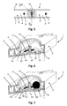
- in einer schematischen Draufsicht von oben ausschnittsweise den Sprüharm nach der Erfindung;
- Figur 6
- in teilgeschnittener Detaildarstellung den Sprüharm nach
Figur 5 gemäß Schnittlinie B - B; - Figur 7
- in teilgeschnittener Detaildarstellung den Sprüharm nach
Figur 5 gemäß Schnittlinie B - B gemäß einer ersten Betriebsstellung; - Figur 8
- in einer geschnittenen Darstellung in Längsrichtung den Sprüharm nach der Erfindung und
- Figur 9
- in perspektivischer Darstellung den Ausschnitt nach
Figur 8 . -
Figur 1 lässt in schematischer Draufsicht von oben einen erfindungsgemäßen Sprüharm 1 erkennen. Ein solcher Sprüharm 1 ist Teil eines ansonsten nicht dargestellten Sprühsystems einer ansonsten ebenfalls nicht dargestellten Geschirrspülmaschine. - Eine Geschirrspülmaschine verfügt über einen Spülbottich, der seinerseits einen Spülraum bereitstellt. Im bestimmungsgemäßen Verwendungsfall der Geschirrspülmaschine dient der Spülraum der Aufnahme von zu reinigendem Spülgut. Innerhalb des Spülraums ist ein Sprühsystem vorgesehen, das der Abgabe von Spülflüssigkeit, der sogenannten Spülflotte dient.
- Zu einem solchen Sprühsystem gehört auch ein verdrehbar innerhalb des Spülraums der Geschirrspülmaschine angeordneter Sprüharm 1, wie er in
Figur 1 dargestellt ist. Typischerweise sind mehrere solcher Sprüharme 1 vorgesehen, die in Höhenrichtung des Spülraums übereinander angeordnet sind und unabhängig voneinander mit Spülflotte beschickt werden können. - Der nach der Erfindung ausgestaltete Sprüharm 1 verfügt über den ersten Flügel 2 und einen zweiten Flügel 3, die sich ausgehend von einer Verteilkammer 14 erstrecken. Die Verteilkammer 14 ist oberseitig mit einer Anschlussöffnung 26 ausgestattet. Sie dient dem Anschluss an eine in den Figuren nicht näher dargestellte Versorgungsleitung, über die im bestimmungsgemäßen Verwendungsfall eine Beschickung des Sprüharms 1 mit Spülflotte erfolgt.
- Die beiden Flügel 2 und 3 verfügen jeweils über einen Hauptkanal 4 sowie über zwei Nebenkanäle 6 und 7. Dabei sind die je Flügel 2 und 3 der jeweilige Hauptkanal 4 sowie die jeweiligen Nebenkanäle 6 und 7 an die Verteilkammer 14 strömungstechnisch angeschlossen.
- Bei einer Beschickung des Sprüharms 1 mit Spülflotte gelangt diese über die Anschlussöffnung 26 in die Verteilkammer 14 des Sprüharms 1. Von dort aus gelangt die Spülflotte in die beiden Hauptkanäle 4 der Flügel 2 und 3 sowie in einen der beiden Nebenkanäle 6 oder 7. Eine gleichzeitige Beschickung der beiden Nebenkanäle 6 und 7 mit Spülflotte findet nicht statt.
- Die Nebenkanäle 6 und 7 verfügen an ihrem der Verteilkammer 14 gegenüberliegenden Ende jeweils über Antriebsdüsen 8 bzw. 9, wobei dem ersten Nebenkanal die Antriebsdüsen 9 und dem zweiten Nebenkanal 7 die Antriebsdüsen 8 zugeordnet sind.
- Bei einer Beschickung des ersten Nebenkanals 6 mit Spülflotte gelangt die Spülflotte zu den Antriebsdüsen 9, aus denen die Spülflotte in Richtung des gestrichelt dargestellten Pfeils 10 jeweils austreten. Hierdurch bedingt wird der um die Drehachse 22 verdrehbar gelagerte Sprüharm 1 in Verdrehbewegung gesetzt, und zwar in Entsprechung des Pfeils 11 links herum, d. h. in eine Linksdrehung entgegen dem Uhrzeigersinn.
- Bei einer Beschickung des zweiten Nebenkanals 7 mit Spülflotte wird diese zu den Antriebsdüsen 8 geleitet, aus denen sie in Entsprechung des Pfeils 12 austritt. In der Konsequenz kommt es zu einer Verdrehbewegung des Sprüharms in Pfeilrichtung 13 rechts herum, d. h. zu einer Rechtsdrehung im Uhrzeigersinn.
- Der Hauptkanal 4 verfügt über Sprühdüsen 5. Bei einer Beschickung des Sprüharms 1 mit Spülflotte gelangt diese über die Verteilkammer 14 in den Hauptkanal 4 und von dort aus zu den Sprühdüsen 5, über welche die Spülflotte auf im Spülraum der Geschirrspülmaschine angeordnetes Spülgut abgegeben wird.
- Im bestimmungsgemäßen Verwendungsfall erfolgt eine Beschickung des Sprüharms 1 mit Spülflotte. Dabei wird Spülflotte zur Abgabe über die Sprühdüsen 5 in den Hauptkanal 4 eingeleitet. Ferner wird Spülflotte entweder in den ersten Nebenkanal 6 oder in den zweiten Nebenkanal 7 eingeleitet, so dass es zu einem Austritt von Spülflotte auch aus den Antriebsdüsen 8 oder 9 kommt. Im Ergebnis dieser Beschickung erfolgt bei gleichzeitiger Abgabe von Spülflotte über die Sprühdüsen 5 entweder eine Linksverdrehbewegung des Sprüharms 1 in Richtung des Pfeils 11 oder einer Rechtsverdrehbewegung des Sprüharms 1 in Richtung des Pfeils 13.
- Eine Beschickung des ersten Nebenkanals 6 oder des zweiten Nebenkanals 7 mit Spülflotte erfolgt in Abhängigkeit der Position der innerhalb der Verteilkammer 14 freibeweglich gelagerten Kugel 15. Diese wirkt entweder mit der Kanalöffnung 16 oder mit der Kanalöffnung 18 zusammen, wobei die Kanalöffnung 16 die strömungstechnische Verbindung zwischen der Verteilkammer 14 und dem ersten Nebenkanal 6 und die Kanalöffnung 18 die strömungstechnische Verbindung zwischen der Verteilkammer 14 und dem zweiten Nebenkanal 7 ausbildet. Dabei verfügt jede Kanalöffnung 16 bzw. 18 verteilkammerseitig über eine Anfasung, die auf den Kugelradius der Kugel 15 abgestimmt ausgebildet ist. Diese Anfasung 17 stellt mithin einen Kugelsitz dar, der bei aufgenommener Kugel 15 einen für Spülflotte dichten Abschluss ausbildet. Mittels der Kugel 15 kann also ein Verschluss entweder der Kanalöffnung 16 oder der Kanalöffnung 18 vorgenommen werden, wobei im verschlossenen Zustand der Kanalöffnung 16 eine Beschickung des zweiten Nebenkanals 7 mit Spülflotte und im verschlossenen Zustand der Kanalöffnung 18 eine Beschickung des ersten Nebenkanals 6 mit Spülflotte stattfindet.
- Die Verteilkammer 14 verfügt der Anschlussöffnung 26 gegenüberliegend über eine Bodenfläche 20. Aus dieser Bodenfläche 20 erhebt sich in Richtung der Drehachse 22 ein Dorn 19. Um diesen Dorn 19 herum kann sich die Kugel 15 in Richtung des Pfeils 21 frei bewegen. Es wird seitens der Verteilkammer 14 mithin ein Ringraum bereitgestellt, wobei die Kugel 15 sich auf der Bodenfläche 20 der Verteilkammer 14 abrollend innerhalb dieses Ringraums bewegen kann.
- Wie insbesondere eine Zusammenschau der
Figuren 5 bis 9 ergibt, ist die Bodenfläche 20 der Verteilkammer 14 in zwei Abschnitte 23 und 24 unterteilt ausgebildet. Dabei ist jeder der beiden Abschnitte 23 und 24 geneigt ausgebildet, d. h. mit Gefälle ausgerüstet, wobei sich das Gefälle einerseits ausgehend von der Drehachse 22 in Richtung des sich an den jeweiligen Abschnitt 23 bzw. 24 anschließenden Hauptkanals 4 sowie andererseits ausgehend von der einen Kanalöffnung 16 bzw. 18 zur gegenüberliegenden Kanalöffnung 18 bzw. 16 erstreckt. So weist beispielsweise der Abschnitt 23 ein Gefälle auf, das sich ausgehend von der Drehachse 22 mit Bezug auf die Zeichnungsebene nachFigur 8 nach rechts sowie gleichzeitig ausgehend von der Kanalöffnung 16 in Richtung der Kanalöffnung 18 erstreckt, was sich insbesondere aus der Darstellung nach denFiguren 6 und 7 ergibt. Das Gefälle des Abschnitts 24 ist in umgekehrter Weise ausgebildet und erstreckt sich einerseits von der Kanalöffnung 18 in Richtung der Kanalöffnung 16 sowie andererseits von der Drehachse 22 mit Bezug auf die Zeichnungsebene nachFigur 8 nach links. - In der Konsequenz dieser Abschnittsgefälle ergibt sich zwischen den beiden Abschnitten 23 und 24 jeweils eine Stufe 25, die auch als Anschlag bezeichnet werden kann. Dabei sind die Abschnitte 23 und 24 in ihren geometrischen Abmessungen derart ausgebildet, dass die zwischen den beiden Abschnitten 23 und 24 ausgebildeten Stufen 25 unter einem radialen Winkel zur Drehachse 22 stehend verlaufen, wie sich insbesondere aus der Darstellung nach den
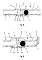
Figuren 8 und 9 ergibt. - Die Funktionsweise des erfindungsgemäß ausgebildeten Sprüharms 1 ergibt sich insbesondere aus der Darstellung nach den
Figuren 2 bis 4 . -
Figur 2 lässt eine Betriebssituation erkennen, der gemäß eine Beschickung des Sprüharms 1 mit Spülflotte stattfindet. In der gezeigten Betriebsstellung ist die Kugel 15 in die Kugelaufnahme der Kanalöffnung 16 gedrückt, wobei sie in dieser Stellung aufgrund der in die Verteilkammer 14 einströmenden Spülflotte gehalten wird. Da die Kugel 15 die Kanalöffnung 16 verschließt, gelangt die in die Verteilkammer 14 einströmende Spülflotte in den Hauptkanal 4 und in den zweiten Nebenkanal 7. Infolgedessen kommt es unter Abgabe von Spülflotte über die Sprühdüsen 5 zu einer Rechtsdrehung in Pfeilrichtung 13 (vgl.Figur 1 ), da bei dem zweiten Nebenkanal 7 eine Beschickung der Antriebsdüsen 8 mit Spülflotte in Entsprechung des Pfeils 12 (vgl.Figur 1 ) stattfindet. - Sobald die Zufuhr mit Spülflotte stoppt, es also zu einer Unterbrechung der Beschickung der Verteilkammer 14 mit Spülflotte kommt, entfällt die von der Spülflotte auf die Kugel 15 ausgeübte Haltekraft. Infolgedessen löst sich die Kugel 15 aus der Kanalöffnung 16 und rollt der Schwerkraft folgend auf dem Abschnitt 23 der Bodenfläche 20 in Richtung des von dem Abschnitt 23 vorgegebenen Gefälles ab (vgl.
Figur 8 ). Dabei kommt die Kugel 15 vor der Kanalöffnung 18 vor der zwischen den beiden Abschnitten 23 und 24 ausgebildeten Stufe 25 zu liegen. Insofern kann diese Stufe 25 auch als Anschlag bezeichnet werden. Dabei liegt die Kugel 15 aufgrund der geometrischen Ausgestaltung der Stufe 15 nicht mittig vor der Kanalöffnung 18, sondern leicht außermittig versetzt. - Kommt es nun zu einer erneuten Beschickung des Sprüharms mit Spülflotte, so wird infolge der einströmenden Spülflotte die Kugel 15 über die Stufe 25 gehoben und infolge des durch die Spülflotte ausgeübten Drucks wird die Kugel 15 in die Kanalöffnung 18 bugsiert. Es kommt zu einem Verschluss der Kanalöffnung 18 und die in die Verteilkammer 14 einströmende Spülflotte gelangt nunmehr nicht mehr in den zweiten Nebenkanal 7 sondern in den ersten Nebenkanal 6.
- Die Freigabe der Kanalöffnung 16 bei gleichzeitigem Verschluss der Kanalöffnung 18 führt dazu, dass es zu einem Drehrichtungswechsel hinsichtlich des Sprüharms 1 kommt, denn die über die Verteilkammer 14 einströmende Spülflotte gelangt nunmehr über den ersten Nebenkanal 6 zu den Antriebsdüsen 9, was zu einer Verdrehbewegung des Sprüharms 1 in Linksrichtung, d. h. in Richtung des Pfeils 11 führt.
- Bei erneutem Druckabfall innerhalb der Verteilkammer 14 fällt die Kugel 15 aus der Kanalöffnung 18 wieder heraus. Da die Stufe 25 leicht versetzt zur Kanalöffnung 18 ausgebildet ist, fällt die Kugel 15 aber nicht zurück auf den Abschnitt 23, sondern folgt vielmehr dem vom Abschnitt 24 bereitgestellten Gefälle bis zur gegenüberliegenden Stufe 25 zwischen den beiden Abschnitten 23 und 24, welche Stufe 25 sich aus der Darstellung nach den
Figuren 8 und 9 ergibt. - Bei einer erneuten Beschickung der Verteilkammer 14 mit Spülflotte wird die Kugel 15 über diese Stufe 25 gehoben und in die Kanalöffnung 16 zum Verschluss derselben eingeführt. Es ergibt sich somit wieder die Betriebssituation, wie sie in
Figur 2 dargestellt ist. -
- 1
- Sprüharm
- 2
- Flügel
- 3
- Flügel
- 4
- Hauptkanal
- 5
- Sprühdüse
- 6
- erster Nebenkanal
- 7
- zweiter Nebenkanal
- 8
- Antriebsdüse
- 9
- Antriebsdüse
- 10
- Pfeil
- 11
- Pfeil (Linksdrehung)
- 12
- Pfeil
- 13
- Pfeil (Rechtsdrehung)
- 14
- Verteilkammer
- 15
- Kugel
- 16
- Kanalöffnung
- 17
- Anfasung
- 18
- Kanalöffnung
- 19
- Dorn
- 20
- Bodenfläche
- 21
- Pfeil
- 22
- Drehachse
- 23
- Abschnitt
- 24
- Abschnitt
- 25
- Stufe (Anschlag)
- 26
- Anschlussöffnung
Claims (13)
- Geschirrspülmaschine mit einem Spülraum und einem im Spülraum vorgesehenen Sprühsystem, das einen drehbar gelagerten Sprüharm (1) aufweist, wobei der Sprüharm (1) Antriebsdüsen (8, 9) aufweist, welche Antriebsdüsen (8, 9) einem Drehantrieb des Sprüharms (1) in Linksrichtung einerseits sowie in Rechtsrichtung andererseits dienen,
dadurch gekennzeichnet,
dass der Sprüharm (1) eine Verteilkammer (14), mit der die Antriebsdüsen (8,9) strömungstechnisch verbunden sind, und ein beweglich innerhalb der Verteilkammer (14) angeordnetes Steuerelement aufweist, welches abwechselnd entweder die Antriebsdüsen (9) für einen Drehantrieb des Sprüharms (1) in Linksrichtung oder die Antriebsdüsen (8) für einen Drehantrieb des Sprüharms (1) in Rechtsrichtung freigibt. - Geschirrspülmaschine nach Anspruch 1,
dadurch gekennzeichnet,
dass das Steuerelement eine Kugel (15) ist. - Geschirrspülmaschine nach Anspruch 2,
dadurch gekennzeichnet,
dass die Verteilkammer (14) einen Ringraum bereitstellt,
in dem die Kugel (15) zwangsgeführt ist. - Geschirrspülmaschine nach einem der vorhergehenden Ansprüche,
dadurch gekennzeichnet,
dass der Sprüharm (1) zwei Flügel (2, 3) aufweist, die sich jeweils ausgehend von der Verteilkammer (14) erstrecken. - Geschirrspülmaschine nach Anspruch 4,
dadurch gekennzeichnet,
dass jeder Flügel (2, 3) einen Hauptkanal (4) und zumindest einen Nebenkanal (6, 7) aufweist. - Geschirrspülmaschine nach einem der vorhergehenden Ansprüche,
dadurch gekennzeichnet,
dass der Sprüharm (1) zumindest zwei Nebenkanäle (6, 7) aufweist, die jeweils an zumindest eine Antriebsdüse (8, 9) angeschlossen sind. - Geschirrspülmaschine nach einem der vorhergehenden Ansprüche,
dadurch gekennzeichnet,
dass der Sprüharm (1) einen Hauptkanal (4) aufweist, der an eine Mehrzahl von Sprühdüsen (5) angeschlossen ist. - Geschirrspülmaschine nach einem der vorhergehenden Ansprüche 3 bis 7,
dadurch gekennzeichnet,
dass der von der Verteilkammer (14) bereitgestellte Ringraum eine in zwei Abschnitte (23, 24) unterteilte Bodenfläche (20) aufweist. - Geschirrspülmaschine nach Anspruch 8,
dadurch gekennzeichnet,
dass die Abschnitte (23, 24) der Ringraumbodenfläche ein in entgegengesetzter Richtung ausgebildetes Gefälle aufweisen. - Geschirrspülmaschine nach Anspruch 8 oder 9,
dadurch gekennzeichnet,
dass die Abschnitte (23, 24) der Ringraumbodenfläche unter jeweiliger Ausbildung einer Stufe (25) ineinander übergehen. - Geschirrspülmaschine nach einem der vorhergehenden Ansprüche 3 bis 10,
dadurch gekennzeichnet,
dass der Ringraum zwei Überströmungsöffnungen (16, 18) aufweist, mittels welcher die Nebenkanäle (6, 7) strömungstechnisch an die Verteilkammer (14) angeschlossen sind. - Geschirrspülmaschine nach Anspruch 11,
dadurch gekennzeichnet,
dass die zwischen den Abschnitten (23, 24) der Ringraumbodenfläche ausgebildeten Stufen (25) radial versetzt zu den einander gegenüberliegend ausgebildeten Überströmungsöffnungen (16, 18) angeordnet sind. - Geschirrspülmaschine nach einem der Ansprüche 7 bis 12,
dadurch gekennzeichnet,
dass die Sprühdüsen (5), an die ein Hauptkanal (4) angeschlossenen ist, unabhängig von der Positionierung des Steuerelements freigegeben sind.
Applications Claiming Priority (1)
| Application Number | Priority Date | Filing Date | Title |
|---|---|---|---|
| DE102011056083A DE102011056083A1 (de) | 2011-12-06 | 2011-12-06 | Geschirrspülmaschine |
Publications (3)
| Publication Number | Publication Date |
|---|---|
| EP2601878A2 true EP2601878A2 (de) | 2013-06-12 |
| EP2601878A3 EP2601878A3 (de) | 2016-02-17 |
| EP2601878B1 EP2601878B1 (de) | 2017-10-18 |
Family
ID=47504756
Family Applications (1)
| Application Number | Title | Priority Date | Filing Date |
|---|---|---|---|
| EP12401245.1A Active EP2601878B1 (de) | 2011-12-06 | 2012-12-06 | Geschirrspülmaschine mit automatischer Drehrichtungsumkehr des Sprüharms |
Country Status (2)
| Country | Link |
|---|---|
| EP (1) | EP2601878B1 (de) |
| DE (1) | DE102011056083A1 (de) |
Cited By (4)
| Publication number | Priority date | Publication date | Assignee | Title |
|---|---|---|---|---|
| CN109259693A (zh) * | 2018-11-14 | 2019-01-25 | 佛山市顺德区美的洗涤电器制造有限公司 | 用于洗碗机的喷臂组件和洗碗机 |
| WO2019086255A1 (en) | 2017-10-31 | 2019-05-09 | Arcelik Anonim Sirketi | A spray arm |
| WO2019091666A1 (en) | 2017-11-08 | 2019-05-16 | Arcelik Anonim Sirketi | A dishwasher |
| CN109875475A (zh) * | 2019-03-13 | 2019-06-14 | 佛山市顺德区美的洗涤电器制造有限公司 | 洗碗机的喷臂组件和具有其的洗碗机 |
Families Citing this family (1)
| Publication number | Priority date | Publication date | Assignee | Title |
|---|---|---|---|---|
| CN109820466A (zh) * | 2019-04-04 | 2019-05-31 | 杭州老板电器股份有限公司 | 旋转喷臂组件及洗碗机 |
Citations (2)
| Publication number | Priority date | Publication date | Assignee | Title |
|---|---|---|---|---|
| DE3816408A1 (de) | 1988-05-13 | 1989-11-16 | Licentia Gmbh | Geschirrspuelmaschine mit einer umsteuervorrichtung |
| DE10355343B3 (de) | 2003-11-25 | 2005-04-07 | Miele & Cie. Kg | Geschirrspülmaschine mit einer Umwälzpumpe |
Family Cites Families (2)
| Publication number | Priority date | Publication date | Assignee | Title |
|---|---|---|---|---|
| DE7024995U (de) * | 1971-03-11 | Robert Bosch Gmbh | Geschirr spulmaschine | |
| US3160164A (en) * | 1963-10-03 | 1964-12-08 | Tappan Co | Washer with reversing spray assembly |
-
2011
- 2011-12-06 DE DE102011056083A patent/DE102011056083A1/de not_active Withdrawn
-
2012
- 2012-12-06 EP EP12401245.1A patent/EP2601878B1/de active Active
Patent Citations (2)
| Publication number | Priority date | Publication date | Assignee | Title |
|---|---|---|---|---|
| DE3816408A1 (de) | 1988-05-13 | 1989-11-16 | Licentia Gmbh | Geschirrspuelmaschine mit einer umsteuervorrichtung |
| DE10355343B3 (de) | 2003-11-25 | 2005-04-07 | Miele & Cie. Kg | Geschirrspülmaschine mit einer Umwälzpumpe |
Cited By (4)
| Publication number | Priority date | Publication date | Assignee | Title |
|---|---|---|---|---|
| WO2019086255A1 (en) | 2017-10-31 | 2019-05-09 | Arcelik Anonim Sirketi | A spray arm |
| WO2019091666A1 (en) | 2017-11-08 | 2019-05-16 | Arcelik Anonim Sirketi | A dishwasher |
| CN109259693A (zh) * | 2018-11-14 | 2019-01-25 | 佛山市顺德区美的洗涤电器制造有限公司 | 用于洗碗机的喷臂组件和洗碗机 |
| CN109875475A (zh) * | 2019-03-13 | 2019-06-14 | 佛山市顺德区美的洗涤电器制造有限公司 | 洗碗机的喷臂组件和具有其的洗碗机 |
Also Published As
| Publication number | Publication date |
|---|---|
| EP2601878B1 (de) | 2017-10-18 |
| DE102011056083A1 (de) | 2013-06-06 |
| EP2601878A3 (de) | 2016-02-17 |
Similar Documents
| Publication | Publication Date | Title |
|---|---|---|
| EP2404539B1 (de) | Wasserweiche für ein wasserführendes Haushaltsgerät | |
| EP2214546B1 (de) | Wasserführendes haushaltsgerät mit einer wasserweiche | |
| DE60028277T2 (de) | Geschirrspülmaschine mit Sprüharmen | |
| EP2601878B1 (de) | Geschirrspülmaschine mit automatischer Drehrichtungsumkehr des Sprüharms | |
| EP2217125A1 (de) | Wasserführendes haushaltsgerät mit einer wasserweiche | |
| EP2601877B1 (de) | Geschirrspülmaschine mit automatischer Drehrichtungsumkehr des Sprüharms | |
| DE102008037344A1 (de) | Transportspülmaschine und Verfahren zum Betreiben einer Transportspülmaschine | |
| DE102008004258B4 (de) | Haushalt-Waschmaschine mit einer Einspüleinrichtung | |
| DE102013218677A1 (de) | Geschirrspülmaschine | |
| EP2556781B1 (de) | Sprüharmanordnung einer Geschirrspülmaschine | |
| DE19926962B4 (de) | Geschirrspülmaschine mit höhenverstellbarem Korb | |
| DE102004018878B4 (de) | Geschirrspülmaschine mit einem Spülbehälter in dem wenigstens ein Sprüharm angeordnet ist | |
| DE4404369C2 (de) | Zulaufventil für den Sprüharm einer Geschirrspülmaschine | |
| DE102011007685A1 (de) | Geschirrspülmaschine | |
| DE102017105589B4 (de) | Sprüheinrichtung für eine Geschirrspülmaschine | |
| DE10150878B4 (de) | Verteilerkasten einer Waschmaschine und Verfahren zur Einspülung von Waschmittel | |
| DE102011056588B3 (de) | Umwälzpumpe für einen Geschirrspülautomaten | |
| EP3815595B1 (de) | Transportgeschirrspülmaschine | |
| EP3473156B1 (de) | Geschirrspülmaschine | |
| DE102017207985B4 (de) | Gravitationsbasiert schaltbarer Flüssigkeitsausbringer | |
| EP3120747B1 (de) | Waschsystem für eine geschirrspülmaschine, sowie geschirrspülmaschine mit einem solchen waschsystem | |
| EP3586713A1 (de) | Sprüharm für eine geschirrspülmaschine | |
| DE102020104642A1 (de) | Wascharm | |
| EP2606806B1 (de) | Reinigungsgerät mit verminderter Laugenverschleppung | |
| DE10223741A1 (de) | Verteiler für dosierte Mengen eines flüssigen Additivs, insbesondere für die Verwendung in einer Geschirrspülmaschine für die professionelle Anwendung |
Legal Events
| Date | Code | Title | Description |
|---|---|---|---|
| PUAI | Public reference made under article 153(3) epc to a published international application that has entered the european phase |
Free format text: ORIGINAL CODE: 0009012 |
|
| AK | Designated contracting states |
Kind code of ref document: A2 Designated state(s): AL AT BE BG CH CY CZ DE DK EE ES FI FR GB GR HR HU IE IS IT LI LT LU LV MC MK MT NL NO PL PT RO RS SE SI SK SM TR |
|
| AX | Request for extension of the european patent |
Extension state: BA ME |
|
| PUAL | Search report despatched |
Free format text: ORIGINAL CODE: 0009013 |
|
| AK | Designated contracting states |
Kind code of ref document: A3 Designated state(s): AL AT BE BG CH CY CZ DE DK EE ES FI FR GB GR HR HU IE IS IT LI LT LU LV MC MK MT NL NO PL PT RO RS SE SI SK SM TR |
|
| AX | Request for extension of the european patent |
Extension state: BA ME |
|
| RIC1 | Information provided on ipc code assigned before grant |
Ipc: A47L 15/42 20060101ALI20160111BHEP Ipc: A47L 15/23 20060101AFI20160111BHEP |
|
| 17P | Request for examination filed |
Effective date: 20160817 |
|
| RBV | Designated contracting states (corrected) |
Designated state(s): AL AT BE BG CH CY CZ DE DK EE ES FI FR GB GR HR HU IE IS IT LI LT LU LV MC MK MT NL NO PL PT RO RS SE SI SK SM TR |
|
| GRAP | Despatch of communication of intention to grant a patent |
Free format text: ORIGINAL CODE: EPIDOSNIGR1 |
|
| INTG | Intention to grant announced |
Effective date: 20170616 |
|
| GRAS | Grant fee paid |
Free format text: ORIGINAL CODE: EPIDOSNIGR3 |
|
| GRAA | (expected) grant |
Free format text: ORIGINAL CODE: 0009210 |
|
| REG | Reference to a national code |
Ref country code: DE Ref legal event code: R084 Ref document number: 502012011467 Country of ref document: DE |
|
| AK | Designated contracting states |
Kind code of ref document: B1 Designated state(s): AL AT BE BG CH CY CZ DE DK EE ES FI FR GB GR HR HU IE IS IT LI LT LU LV MC MK MT NL NO PL PT RO RS SE SI SK SM TR |
|
| REG | Reference to a national code |
Ref country code: GB Ref legal event code: FG4D Free format text: NOT ENGLISH |
|
| REG | Reference to a national code |
Ref country code: CH Ref legal event code: EP |
|
| REG | Reference to a national code |
Ref country code: GB Ref legal event code: 746 Effective date: 20171018 |
|
| REG | Reference to a national code |
Ref country code: AT Ref legal event code: REF Ref document number: 937207 Country of ref document: AT Kind code of ref document: T Effective date: 20171115 Ref country code: IE Ref legal event code: FG4D Free format text: LANGUAGE OF EP DOCUMENT: GERMAN |
|
| REG | Reference to a national code |
Ref country code: DE Ref legal event code: R096 Ref document number: 502012011467 Country of ref document: DE |
|
| REG | Reference to a national code |
Ref country code: FR Ref legal event code: PLFP Year of fee payment: 6 |
|
| REG | Reference to a national code |
Ref country code: NL Ref legal event code: MP Effective date: 20171018 |
|
| REG | Reference to a national code |
Ref country code: LT Ref legal event code: MG4D |
|
| PG25 | Lapsed in a contracting state [announced via postgrant information from national office to epo] |
Ref country code: NL Free format text: LAPSE BECAUSE OF FAILURE TO SUBMIT A TRANSLATION OF THE DESCRIPTION OR TO PAY THE FEE WITHIN THE PRESCRIBED TIME-LIMIT Effective date: 20171018 |
|
| PG25 | Lapsed in a contracting state [announced via postgrant information from national office to epo] |
Ref country code: ES Free format text: LAPSE BECAUSE OF FAILURE TO SUBMIT A TRANSLATION OF THE DESCRIPTION OR TO PAY THE FEE WITHIN THE PRESCRIBED TIME-LIMIT Effective date: 20171018 Ref country code: LT Free format text: LAPSE BECAUSE OF FAILURE TO SUBMIT A TRANSLATION OF THE DESCRIPTION OR TO PAY THE FEE WITHIN THE PRESCRIBED TIME-LIMIT Effective date: 20171018 Ref country code: SE Free format text: LAPSE BECAUSE OF FAILURE TO SUBMIT A TRANSLATION OF THE DESCRIPTION OR TO PAY THE FEE WITHIN THE PRESCRIBED TIME-LIMIT Effective date: 20171018 Ref country code: NO Free format text: LAPSE BECAUSE OF FAILURE TO SUBMIT A TRANSLATION OF THE DESCRIPTION OR TO PAY THE FEE WITHIN THE PRESCRIBED TIME-LIMIT Effective date: 20180118 Ref country code: FI Free format text: LAPSE BECAUSE OF FAILURE TO SUBMIT A TRANSLATION OF THE DESCRIPTION OR TO PAY THE FEE WITHIN THE PRESCRIBED TIME-LIMIT Effective date: 20171018 |
|
| PG25 | Lapsed in a contracting state [announced via postgrant information from national office to epo] |
Ref country code: GR Free format text: LAPSE BECAUSE OF FAILURE TO SUBMIT A TRANSLATION OF THE DESCRIPTION OR TO PAY THE FEE WITHIN THE PRESCRIBED TIME-LIMIT Effective date: 20180119 Ref country code: IS Free format text: LAPSE BECAUSE OF FAILURE TO SUBMIT A TRANSLATION OF THE DESCRIPTION OR TO PAY THE FEE WITHIN THE PRESCRIBED TIME-LIMIT Effective date: 20180218 Ref country code: LV Free format text: LAPSE BECAUSE OF FAILURE TO SUBMIT A TRANSLATION OF THE DESCRIPTION OR TO PAY THE FEE WITHIN THE PRESCRIBED TIME-LIMIT Effective date: 20171018 Ref country code: RS Free format text: LAPSE BECAUSE OF FAILURE TO SUBMIT A TRANSLATION OF THE DESCRIPTION OR TO PAY THE FEE WITHIN THE PRESCRIBED TIME-LIMIT Effective date: 20171018 Ref country code: BG Free format text: LAPSE BECAUSE OF FAILURE TO SUBMIT A TRANSLATION OF THE DESCRIPTION OR TO PAY THE FEE WITHIN THE PRESCRIBED TIME-LIMIT Effective date: 20180118 Ref country code: HR Free format text: LAPSE BECAUSE OF FAILURE TO SUBMIT A TRANSLATION OF THE DESCRIPTION OR TO PAY THE FEE WITHIN THE PRESCRIBED TIME-LIMIT Effective date: 20171018 |
|
| REG | Reference to a national code |
Ref country code: DE Ref legal event code: R097 Ref document number: 502012011467 Country of ref document: DE |
|
| PG25 | Lapsed in a contracting state [announced via postgrant information from national office to epo] |
Ref country code: SK Free format text: LAPSE BECAUSE OF FAILURE TO SUBMIT A TRANSLATION OF THE DESCRIPTION OR TO PAY THE FEE WITHIN THE PRESCRIBED TIME-LIMIT Effective date: 20171018 Ref country code: EE Free format text: LAPSE BECAUSE OF FAILURE TO SUBMIT A TRANSLATION OF THE DESCRIPTION OR TO PAY THE FEE WITHIN THE PRESCRIBED TIME-LIMIT Effective date: 20171018 Ref country code: DK Free format text: LAPSE BECAUSE OF FAILURE TO SUBMIT A TRANSLATION OF THE DESCRIPTION OR TO PAY THE FEE WITHIN THE PRESCRIBED TIME-LIMIT Effective date: 20171018 Ref country code: CZ Free format text: LAPSE BECAUSE OF FAILURE TO SUBMIT A TRANSLATION OF THE DESCRIPTION OR TO PAY THE FEE WITHIN THE PRESCRIBED TIME-LIMIT Effective date: 20171018 |
|
| REG | Reference to a national code |
Ref country code: CH Ref legal event code: PL |
|
| PLBE | No opposition filed within time limit |
Free format text: ORIGINAL CODE: 0009261 |
|
| STAA | Information on the status of an ep patent application or granted ep patent |
Free format text: STATUS: NO OPPOSITION FILED WITHIN TIME LIMIT |
|
| PG25 | Lapsed in a contracting state [announced via postgrant information from national office to epo] |
Ref country code: IT Free format text: LAPSE BECAUSE OF FAILURE TO SUBMIT A TRANSLATION OF THE DESCRIPTION OR TO PAY THE FEE WITHIN THE PRESCRIBED TIME-LIMIT Effective date: 20171018 Ref country code: PL Free format text: LAPSE BECAUSE OF FAILURE TO SUBMIT A TRANSLATION OF THE DESCRIPTION OR TO PAY THE FEE WITHIN THE PRESCRIBED TIME-LIMIT Effective date: 20171018 Ref country code: SM Free format text: LAPSE BECAUSE OF FAILURE TO SUBMIT A TRANSLATION OF THE DESCRIPTION OR TO PAY THE FEE WITHIN THE PRESCRIBED TIME-LIMIT Effective date: 20171018 Ref country code: RO Free format text: LAPSE BECAUSE OF FAILURE TO SUBMIT A TRANSLATION OF THE DESCRIPTION OR TO PAY THE FEE WITHIN THE PRESCRIBED TIME-LIMIT Effective date: 20171018 |
|
| REG | Reference to a national code |
Ref country code: IE Ref legal event code: MM4A |
|
| 26N | No opposition filed |
Effective date: 20180719 |
|
| PG25 | Lapsed in a contracting state [announced via postgrant information from national office to epo] |
Ref country code: MT Free format text: LAPSE BECAUSE OF FAILURE TO SUBMIT A TRANSLATION OF THE DESCRIPTION OR TO PAY THE FEE WITHIN THE PRESCRIBED TIME-LIMIT Effective date: 20171018 Ref country code: LU Free format text: LAPSE BECAUSE OF NON-PAYMENT OF DUE FEES Effective date: 20171206 |
|
| REG | Reference to a national code |
Ref country code: BE Ref legal event code: MM Effective date: 20171231 |
|
| PG25 | Lapsed in a contracting state [announced via postgrant information from national office to epo] |
Ref country code: IE Free format text: LAPSE BECAUSE OF NON-PAYMENT OF DUE FEES Effective date: 20171206 |
|
| PG25 | Lapsed in a contracting state [announced via postgrant information from national office to epo] |
Ref country code: LI Free format text: LAPSE BECAUSE OF NON-PAYMENT OF DUE FEES Effective date: 20171231 Ref country code: CH Free format text: LAPSE BECAUSE OF NON-PAYMENT OF DUE FEES Effective date: 20171231 Ref country code: SI Free format text: LAPSE BECAUSE OF FAILURE TO SUBMIT A TRANSLATION OF THE DESCRIPTION OR TO PAY THE FEE WITHIN THE PRESCRIBED TIME-LIMIT Effective date: 20171018 Ref country code: BE Free format text: LAPSE BECAUSE OF NON-PAYMENT OF DUE FEES Effective date: 20171231 |
|
| REG | Reference to a national code |
Ref country code: AT Ref legal event code: MM01 Ref document number: 937207 Country of ref document: AT Kind code of ref document: T Effective date: 20171206 |
|
| PG25 | Lapsed in a contracting state [announced via postgrant information from national office to epo] |
Ref country code: AT Free format text: LAPSE BECAUSE OF NON-PAYMENT OF DUE FEES Effective date: 20171206 |
|
| PG25 | Lapsed in a contracting state [announced via postgrant information from national office to epo] |
Ref country code: HU Free format text: LAPSE BECAUSE OF FAILURE TO SUBMIT A TRANSLATION OF THE DESCRIPTION OR TO PAY THE FEE WITHIN THE PRESCRIBED TIME-LIMIT; INVALID AB INITIO Effective date: 20121206 Ref country code: MC Free format text: LAPSE BECAUSE OF FAILURE TO SUBMIT A TRANSLATION OF THE DESCRIPTION OR TO PAY THE FEE WITHIN THE PRESCRIBED TIME-LIMIT Effective date: 20171018 |
|
| PG25 | Lapsed in a contracting state [announced via postgrant information from national office to epo] |
Ref country code: CY Free format text: LAPSE BECAUSE OF NON-PAYMENT OF DUE FEES Effective date: 20171018 |
|
| PG25 | Lapsed in a contracting state [announced via postgrant information from national office to epo] |
Ref country code: MK Free format text: LAPSE BECAUSE OF FAILURE TO SUBMIT A TRANSLATION OF THE DESCRIPTION OR TO PAY THE FEE WITHIN THE PRESCRIBED TIME-LIMIT Effective date: 20171018 |
|
| PG25 | Lapsed in a contracting state [announced via postgrant information from national office to epo] |
Ref country code: TR Free format text: LAPSE BECAUSE OF FAILURE TO SUBMIT A TRANSLATION OF THE DESCRIPTION OR TO PAY THE FEE WITHIN THE PRESCRIBED TIME-LIMIT Effective date: 20171018 |
|
| PG25 | Lapsed in a contracting state [announced via postgrant information from national office to epo] |
Ref country code: PT Free format text: LAPSE BECAUSE OF FAILURE TO SUBMIT A TRANSLATION OF THE DESCRIPTION OR TO PAY THE FEE WITHIN THE PRESCRIBED TIME-LIMIT Effective date: 20171018 |
|
| PG25 | Lapsed in a contracting state [announced via postgrant information from national office to epo] |
Ref country code: AL Free format text: LAPSE BECAUSE OF FAILURE TO SUBMIT A TRANSLATION OF THE DESCRIPTION OR TO PAY THE FEE WITHIN THE PRESCRIBED TIME-LIMIT Effective date: 20171018 |
|
| PGFP | Annual fee paid to national office [announced via postgrant information from national office to epo] |
Ref country code: GB Payment date: 20221220 Year of fee payment: 11 Ref country code: FR Payment date: 20221222 Year of fee payment: 11 |
|
| P01 | Opt-out of the competence of the unified patent court (upc) registered |
Effective date: 20230529 |
|
| PGFP | Annual fee paid to national office [announced via postgrant information from national office to epo] |
Ref country code: DE Payment date: 20231231 Year of fee payment: 12 |