EP2597506A1 - Mikroskopbeleuchtungssystem und -verfahren - Google Patents
Mikroskopbeleuchtungssystem und -verfahren Download PDFInfo
- Publication number
- EP2597506A1 EP2597506A1 EP12194650.3A EP12194650A EP2597506A1 EP 2597506 A1 EP2597506 A1 EP 2597506A1 EP 12194650 A EP12194650 A EP 12194650A EP 2597506 A1 EP2597506 A1 EP 2597506A1
- Authority
- EP
- European Patent Office
- Prior art keywords
- illumination
- microscope
- beam path
- objective
- focal plane
- Prior art date
- Legal status (The legal status is an assumption and is not a legal conclusion. Google has not performed a legal analysis and makes no representation as to the accuracy of the status listed.)
- Granted
Links
Images

Classifications
-
- G—PHYSICS
- G02—OPTICS
- G02B—OPTICAL ELEMENTS, SYSTEMS OR APPARATUS
- G02B21/00—Microscopes
- G02B21/06—Means for illuminating specimens
-
- G—PHYSICS
- G02—OPTICS
- G02B—OPTICAL ELEMENTS, SYSTEMS OR APPARATUS
- G02B21/00—Microscopes
- G02B21/0004—Microscopes specially adapted for specific applications
- G02B21/002—Scanning microscopes
- G02B21/0024—Confocal scanning microscopes (CSOMs) or confocal "macroscopes"; Accessories which are not restricted to use with CSOMs, e.g. sample holders
- G02B21/0032—Optical details of illumination, e.g. light-sources, pinholes, beam splitters, slits, fibers
-
- G—PHYSICS
- G02—OPTICS
- G02B—OPTICAL ELEMENTS, SYSTEMS OR APPARATUS
- G02B21/00—Microscopes
- G02B21/0004—Microscopes specially adapted for specific applications
- G02B21/002—Scanning microscopes
- G02B21/0024—Confocal scanning microscopes (CSOMs) or confocal "macroscopes"; Accessories which are not restricted to use with CSOMs, e.g. sample holders
- G02B21/0028—Confocal scanning microscopes (CSOMs) or confocal "macroscopes"; Accessories which are not restricted to use with CSOMs, e.g. sample holders specially adapted for specific applications, e.g. for endoscopes, ophthalmoscopes, attachments to conventional microscopes
-
- G—PHYSICS
- G02—OPTICS
- G02B—OPTICAL ELEMENTS, SYSTEMS OR APPARATUS
- G02B27/00—Optical systems or apparatus not provided for by any of the groups G02B1/00 - G02B26/00, G02B30/00
- G02B27/58—Optics for apodization or superresolution; Optical synthetic aperture systems
-
- G—PHYSICS
- G02—OPTICS
- G02B—OPTICAL ELEMENTS, SYSTEMS OR APPARATUS
- G02B21/00—Microscopes
- G02B21/0004—Microscopes specially adapted for specific applications
- G02B21/002—Scanning microscopes
- G02B21/0024—Confocal scanning microscopes (CSOMs) or confocal "macroscopes"; Accessories which are not restricted to use with CSOMs, e.g. sample holders
- G02B21/0052—Optical details of the image generation
- G02B21/0076—Optical details of the image generation arrangements using fluorescence or luminescence
-
- G—PHYSICS
- G02—OPTICS
- G02B—OPTICAL ELEMENTS, SYSTEMS OR APPARATUS
- G02B21/00—Microscopes
- G02B21/16—Microscopes adapted for ultraviolet illumination ; Fluorescence microscopes
-
- G—PHYSICS
- G02—OPTICS
- G02B—OPTICAL ELEMENTS, SYSTEMS OR APPARATUS
- G02B21/00—Microscopes
- G02B21/36—Microscopes arranged for photographic purposes or projection purposes or digital imaging or video purposes including associated control and data processing arrangements
- G02B21/365—Control or image processing arrangements for digital or video microscopes
- G02B21/367—Control or image processing arrangements for digital or video microscopes providing an output produced by processing a plurality of individual source images, e.g. image tiling, montage, composite images, depth sectioning, image comparison
Definitions
- the present invention relates to a microscope illumination system and a corresponding method for providing a microscope illumination for localization microscopy, wherein in particular a switch to another type of illumination for scanning microscopes, in particular confocal microscopes, should be possible.
- the invention relates to the technical implementation of a method of localization microscopy for over-resolution.
- Such methods are characterized in that when taking a picture only a few object points simultaneously emit light. If the points are much farther apart than the optical resolution, the location of these points can be determined via mathematical methods for determining the center of gravity with an accuracy which is higher than the optical resolution of the objective used. If many of these individual images are summed up, in which different object points are imaged in each case, finally the entire object can be depicted with super-resolution.
- Known embodiments of such methods differ in terms of how to ensure that only a few object points to emit light simultaneously. Designations for such methods are, for example, PALM, STORM or GSDIM. The latter method will be briefly described below.
- GSDIM stands for "Ground State Depletion microscopy followed by Individual Molecule return”.
- fluorophores with triplicate states also "dark states" are used.
- a dye molecule is brought from the ground state to an excited state by irradiation of appropriate laser power. From the excited state there is a transition to the triple state, this triple state has a much longer life (about 100 ms) than the excited single state (of only about 3 ns), so that accumulate at sufficient light intensity, the molecules in triplicate state. From the triplicate state, the molecules return to their ground state under spontaneous emission. Individual images of these spontaneous emissions are recorded, whereby the locations of the spontaneous emissions can be determined via the mentioned mathematical methods with an accuracy which is higher than the optical resolution.
- the achievable resolution is between 20 and 25 nm, generally less than 60 nm. The achievable resolution also depends on the laser power and the resolution of the camera used.
- the technical prerequisite for the realization of GSDIM is the fluorescence excitation of the preparation with high light output.
- This can be done via a suitable laser lighting.
- This in turn can be controlled by a TIRF lighting device ("Total Internal Reflection Fluorescence microscopy "), which focuses the laser beam into the objective pupil (rear focal plane of the objective), has the advantage that homogeneous illumination of the specimen is obtained at a large depth of field of the illumination Laser reduced so that the illuminated specimen field in comparison to the TIRF illumination is only about a quarter (for example, the diameter of the illuminated specimen field is about 60 microns when using a lens with magnification 100 times, while TIRF illumination with this diameter approx 250 ⁇ m).
- FIGS. 1a and 1b The operation of switching between TIRF illumination and a lighting for GSDIM is described below with reference to FIGS. 1a and 1b shown schematically.
- the optical axis of the lens can be achieved than in normal fluorescence microscopy (layer areas of typically 500 nm).
- TIRF microscopy the excitation light is coupled in at the edge of the lens so that it falls onto the cover glass at the required shallow angle.
- FIG. 1a schematically shows a typical TIRF illumination with illumination beam path 16:
- the outgoing light from a light source 18 (usually a laser) (dashed lines) is collimated by a collimator 17.
- the collimated light is focused by the scanning eyepiece 13.
- the transport optical system 14 images the focus into the rear focal plane 6 of the objective 7, wherein the light is previously reflected on the divider mirror 19.
- the splitter mirror can produce, for example, a physical, a geometric, a color or a polarization-type division.
- the transport optics 14 is necessary due to the mechanical conditions of a microscope stand, since the scan ocular 13 can not be built close enough to the lens 7 to focus directly in the rear focal plane 6.
- the scan ocular 13 is designed to be focused (indicated by an arrow).
- the objective 7 images the laser beam focused into its rear focal plane 6 into a parallel beam in the space of the preparation 8 (object space). This parallel beam illuminates a circle in the preparation 8 with diameter D a (typically about 250 ⁇ m).
- the tiltability of the scanning mirror 12 (shown schematically) is crucial.
- the focus is shifted in the rear focal plane 6 perpendicular to the optical axis of the lens. This causes the laser beam to penetrate the preparation 8 at an angle which is dependent on the tilting of the scanning mirror 12. If this angle is greater than the angle of total reflection between cover glass and preparation medium, one speaks - as explained above - of TIRF microscopy.
- the specimen illuminated in this way now emits fluorescent light (drawn in solid lines).
- This light passes through the beam splitter 19 and generates an image 22 by means of a tube lens 21.
- FIG. 1b shows a typical lighting for a GSDIM process. Decisive for this is a high laser power per illuminated preparation area. The laser power must therefore be effective on a greatly reduced preparation diameter D b (typically about 60 microns).
- D b typically about 60 microns.
- TIRF illumination device in front of the scanning mirror 12, a telescope 11 which reduces the beam diameter (drawn in dashed lines) is folded into the beam path. This reduces the illuminated in the specimen circuit to a diameter D b , here of about 60 microns, whereby the power density is increased by a factor of about 18.
- the laser beam hits the specimen under normal incidence. In rare cases, an observation is made made with tilted scanning mirror 12. For the rest, please refer to the explanatory notes FIG. 1a directed.
- confocal microscopy Another application is confocal microscopy.
- confocal microscopy in contrast to conventional light microscopy (also known as "widefield microscopy"), not all of the specimen is illuminated, but at any one time only a section or point of the specimen.
- conventional light microscopy also known as "widefield microscopy”
- the specimen With a suitably focused laser or a point light source, the specimen is spot-illuminated and scanned over the microscope objective. In this way, the light intensities of the reflected light can be measured successively at all scanned locations of the specimen. Subsequently, a picture of the preparation is constructed from this.
- the excitation light of the laser or the point light source is focussed into the specimen in different focal planes.
- the reflected light from the specimen is usually imaged by the same lens with which it is focused on the specimen on a pinhole, from which it reaches a detector.
- Excitation and detection focus are confocal, that is, one above the other.
- confocal microscopy Light from planes outside the focal plane can not pass through the pinhole on the detector.
- FIG. 6 of this document shows a typical structure of a laser scanning microscope for confocal microscopy.
- Figure 7 of this document shows the typical structure of a TIRF microscope.
- this US patent deals with an alternative solution for such a combination by using an optical system that can be introduced into the optical path of the confocal microscope to move the laser light into the rear focal plane to focus the lens, wherein the main rays at the location of the rear focal plane parallel to the optical axis. The latter condition is necessary for TIRF illumination.
- an alternative embodiment of said combination is in this patent the use of a complete Umlenkstrahlengangs described in order to switch between TIRF and confocal microscopy.
- an optical arrangement in the illumination beam path of a confocal laser microscope which serves the optimal illumination in reducing losses of the excitation light.
- the laser of the confocal microscope is followed by a lens with a downstream vario optic.
- the narrow cross section of the parallel laser beam path is widened.
- the thus expanded beam is directed to a scanning mirror, which in turn directs it in the direction of the lens.
- the lens focuses the beam passing through its entrance pupil onto the object.
- the illumination diameter of the illumination beam path can be adapted more or less exactly to the entrance pupil of the respectively used objective in order to avoid light losses.
- the present invention has for its object to provide a suitable non-confocal illumination, in particular for the Localization microscopy, in particular for a GSDIM method, provide that can be used independently of a TIRF illumination.
- a suitable non-confocal illumination in particular for the Localization microscopy, in particular for a GSDIM method, provide that can be used independently of a TIRF illumination.
- such illumination should be switchable to a suitable for confocal microscopy illumination.
- a microscope illumination system for localization microscopy which will be referred to more generally as the second type of microscope illumination, wherein a switch between a first type of microscope illumination, in particular illumination for confocal microscopy, and this second type of microscope illumination
- This microscope illumination system has a microscope illumination unit which has the following components for providing the first microscope illumination: an illumination source device for generating an illumination beam path running parallel to the optical axis, a scanning mirror device for deflecting the illumination beam path in a plane perpendicular to the optical axis, and a scanning eyepiece and a downstream one Scantubus lens for imaging the scanning mirror device in the rear focal plane of a microscope objective and for widening the illumination beam path, wherein the microscope objective focuses the illumination beam path on a specimen to be examined.
- this microscope illumination unit has a focusing lens which can be introduced into the illumination beam path in such a way that it is focused into the rear focal plane of the microscope objective.
- the first type of microscope illumination is particularly suitable for laser scanning microscope illumination, in particular for confocal microscopy, while the second type of microscope illumination is particularly suitable for localization microscopy, more particularly for the GSDIM already described.
- the invention proposes a combination of microscope illuminations, which in particular for confocal microscopy and localization microscopy.
- the advantage of this combination is that confocal microscopes are recognized prior art for high resolution optical fluorescence microscopy and for quantitative issues at the same time highest optical resolution can be used.
- the localization or localization microscopy described in the introduction is in the same direction, so that it offers enormous advantages for the user to be able to combine a confocal microscope with a localization microscope. In particular, the same lasers can be used for the corresponding microscope illumination types.
- the invention takes into account the different optical imaging ratios in the two types of microscope illumination described and makes a corresponding adjustment in a way that can be switched between the two microscope illumination modes.
- a confocal microscope illumination was assumed for the purpose of further explanation in the first type of microscope illumination.
- a microscope illumination for GSDIM was assumed.
- the switching of a confocal microscopy illumination into a GSDIM illumination is described.
- this description can conversely be used for switching from a GSDIM illumination to a confocal microscope illumination. Both directions of switching are equivalent.
- An illumination source device initially serves to generate an illumination beam path running parallel to the optical axis.
- a collimated laser beam is usually used.
- to provide the first namely confocal Mikroskopbeleuchtungsart a Fernrohroptik in the illumination beam path arranged, which widens the illumination beam path in diameter.
- This illumination beam path (expanded laser beam), which extends parallel to the optical axis, strikes a scanning mirror device with which the illumination beam path can be deflected in a known manner in a plane perpendicular to the optical axis. If the optical axis is identified with the z-direction, then said plane is the x-y plane.
- This scanning mirror device serves in the manner described above to scan the specimen to be examined in a focal plane.
- the microscope illumination unit has a scan eyepiece and a downstream scan tube lens. Both components can be single lenses or compound lens systems. Scanocular and Scantubus lens work together to provide two functions. On the one hand, the beam diameter is widened, in particular so far that the rear focal plane of a microscope objective is completely illuminated.
- the scanning mirror device which in particular has a single or a plurality of scanning mirrors connected in series, is imaged in the rear focal plane of the microscope objective. The lens finally focuses the laser beam on the specimen. In this arrangement, a tilting of the laser beam by the scanning mirror device leads to a tilting of the laser beam at the location of the rear focal plane and thus to an offset of the focal point in the preparation perpendicular to the optical axis.
- the introduction of a focusing lens in the illumination beam path is essential, which is focused by this focusing lens, the laser beam is no longer in the preparation, but now in the rear focal plane of the microscope objective.
- the focusing lens may again be a single lens or a composite lens system.
- the illumination source device for the first, confocal illumination type has a telescope optics for widening the illumination beam path.
- Such expansion is often necessary because the laser beam, before it traverses the telescope optics passes through an acousto-optic beam splitter (abbreviated AOBS), which in turn allows only a certain maximum beam diameter, which is usually smaller than the beam diameter required at the scan ocular.
- AOBS acousto-optic beam splitter
- the Fernrohroptik thus serves the expansion of the laser beam between AOBS and Scanokular.
- the telescope optics are removed from the illumination beam path. In this way, the diameter of the illuminated preparation field is reduced and the light intensity on the preparation increased by about a factor of 25. This arrangement thus makes it possible to carry out localization microscopy with high illumination intensities.
- the focusing lens or - in Matgliedrigem structure - a part of it is designed to be displaceable in the direction of the optical axis, so that the focus can be adapted to lenses with different position of the rear focal plane.
- the microscope illumination system according to the invention is particularly suitable for switching between a laser scanning microscope illumination, in particular for confocal microscopy, and a localization microscope illumination, in particular for a GSDIM method.
- the invention further relates to a microscope with a microscope objective and a microscope illumination system according to the invention, as detailed above.
- a microscope in particular a confocal or localization microscope, is generally known from the prior art. In that regard, it is waived further explanations in this context.
- the light emitted by the specimen is focused via the microscope objective and further downstream optics into a confocal aperture in order to access a detector from there.
- the decoupling of this observation beam path emanating from the specimen takes place between the scanning tube lens and the objective.
- a splitter mirror is arranged there
- the invention further relates to a method for providing a lighting for the localization microscopy, this type of illumination is to be made possible in particular by switching from the Konfokalmikroskopiebeleuchtung.
- this type of illumination is to be made possible in particular by switching from the Konfokalmikroskopiebeleuchtung.
- FIGS. 1a and 1b illustrated lighting units have been explained in detail in the introduction to the description.
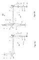
- FIG. 2 shows very schematically an embodiment of a microscope illumination system according to the invention, wherein in FIG. 2a a microscope illumination unit 100 for a confocal microscope and in FIG. 2b this - modified accordingly - microscope illumination unit 100 is shown for a GSDIM method.
- the illumination beam path 16 starting from the light source 32 (usually a laser or another point light source) initially from bottom to top.
- a collimator optics 31 collimates the light.
- a laser beam whose wavelength is designed to excite fluorescence emissions in the colored preparation 8.
- the illumination source device designated generally by 10, has, in addition to the light source 32 and a collimator optics 31 in FIG. 2a a Fernrohroptik 1 for expanding the laser beam, shown as illumination beam path 16, on.
- the expanded laser beam strikes a scanning mirror device 2, here indicated as a scanning mirror.
- the scanning mirror can be tilted in two spatial directions such that the resulting laser beam is tilted in a plane perpendicular to the optical axis 9.
- the scanocular is designated 3.
- the laser beam as a rule passes through an acousto-optic beam splitter (AOBS) (not shown), which separates the illumination beam path from the observation beam path and which only allows a certain maximum beam diameter smaller than that on the scanning eyepiece 3 is needed. Therefore, in FIG. 2a the Fernrohroptik 1 provided for beam expansion in front of the Scanokular 3.
- AOBS acousto-optic beam splitter
- the scanning eyepiece 3 is in FIG. 2a a Scantubuslinse 5 and a mirror 29 downstream.
- Scanocular 3 and Scantubus lens 5 work together as another telescope optics with two functions.
- the beam diameter is again widened so that the rear focal plane 6 of the lens 7 is completely and thus optimally illuminated.
- the scanning mirror is imaged at the location of the rear focal plane 6.
- the scanning mirror device 2 is thus located at a location conjugate to the focal plane 6.
- the objective 7 finally focuses the laser beam on the preparation 8.
- the preparation 8 is suitably colored with fluorophores, so that the incident laser radiation leads to fluorescence excitation. By tilting the scanning mirror or by suitable control of the scanning mirror device 2, the laser beam focus is moved in the focal plane of the preparation 8, so that scanning in a plane perpendicular to the optical axis 9 is possible.
- FIG. 2b schematically shows the microscope illumination unit 100 FIG. 2a , which is now set up to provide a second microscope illumination type, here for a GSDIM method, in a microscope 200. Identical components are provided with the same reference numerals, in which case a further explanation is omitted.
- a focusing lens 4 is brought into the beam path 16. This focusing lens 4, together with the scanning tube lens 5, ensures that the laser beam is focused in the rear focal plane 6 of the microscope objective 7.
- the focusing lens 4 is introduced into the illumination beam path 16 between the scanning eyepiece 3 and the scanning tube lens 5.
- the double arrow below the focusing lens 4 indicates that it is designed to be displaceable in the direction of the optical axis 9. In this way, the position of the focusing lens 4 at different Layers of focal planes 6 are adjusted when different lenses 7 are used.
- the telescope optics 1 is removed from the beam path 16. In this way it can be ensured that the illumination beam path is not widened and thus falls onto the preparation 8 with a high surface intensity.
- the intensity of the preparation 8 can be increased by about 25 times. Such power densities are necessary to bring sufficient excitation energy to the irradiated preparation surface.
Landscapes
- Physics & Mathematics (AREA)
- General Physics & Mathematics (AREA)
- Optics & Photonics (AREA)
- Chemical & Material Sciences (AREA)
- Analytical Chemistry (AREA)
- Health & Medical Sciences (AREA)
- General Health & Medical Sciences (AREA)
- Ophthalmology & Optometry (AREA)
- Radiology & Medical Imaging (AREA)
- Surgery (AREA)
- Microscoopes, Condenser (AREA)
Abstract
Description
- Die vorliegende Erfindung betrifft ein Mikroskopbeleuchtungssystem und ein entsprechendes Verfahren zur Bereitstellung einer Mikroskopbeleuchtung für die Lokalisierungsmikroskopie, wobei insbesondere eine Umschaltung in eine andere Beleuchtungsart für Scanmikroskope, insbesondere Konfokalmikroskope, möglich sein soll.
- Die Erfindung bezieht sich auf die technische Umsetzung eines Verfahrens der Lokalisierungsmikroskopie zur Überauflösung. Solche Verfahren zeichnen sich dadurch aus, dass bei der Aufnahme eines Bildes immer nur wenige Objektpunkte gleichzeitig Licht aussenden. Liegen die Punkte deutlich weiter voneinander entfernt als die optische Auflösung, kann der Ort dieser Punkte über mathematische Verfahren zur Schwerpunktsbestimmung mit einer Genauigkeit bestimmt werden, die höher ist als die optische Auflösung des verwendeten Objektivs. Werden viele dieser Einzelbilder aufsummiert, bei denen jeweils unterschiedliche Objektpunkte abgebildet werden, kann schließlich das gesamte Objekt mit Überauflösung bildlich dargestellt werden. Bekannte Ausführungsformen solcher Verfahren unterscheiden sich im Hinblick darauf, wie sichergestellt wird, dass nur wenige Objektpunkte gleichzeitig Licht aussenden. Bezeichnungen für solche Verfahren sind beispielsweise PALM, STORM oder GSDIM. Letzteres Verfahren soll nachfolgend kurz beschrieben werden.
- GSDIM steht für (engl.) "Ground State Depletion microscopy followed by Individual Molecule return". Für dieses Verfahren werden Fluorophore mit Tripletzuständen (auch "dark states") verwendet. Zunächst wird ein Farbstoffmolekül aus dem Grundzustand in einen angeregten Zustand durch Einstrahlung entsprechender Laserleistung gebracht. Vom angeregten Zustand aus erfolgt ein Übergang in den Tripletzustand, wobei dieser Tripletzustand eine weitaus höhere Lebensdauer (ca. 100 ms) als der angeregte Singletzustand (von nur etwa 3 ns) besitzt, so dass bei ausreichender Lichtintensität die Moleküle im Tripletzustand akkumulieren. Aus dem Tripletzustand gehen die Moleküle unter spontaner Emission in den Grundzustand zurück. Es werden Einzelbilder dieser spontanen Emissionen aufgenommen, wobei die Orte der spontanen Emissionen über die erwähnten mathematischen Verfahren mit einer Genauigkeit bestimmt werden können, die höher ist als die optische Auflösung. Die erreichbare Auflösung liegt zwischen 20 und 25 nm, im Allgemeinen unter 60 nm. Die erzielbare Auflösung hängt auch von der Laserleistung und der Auflösung der verwendeten Kamera ab.
- Die technische Hauptvoraussetzung zur Realisierung von GSDIM ist die Fluoreszenzanregung des Präparats mit hoher Lichtleistung. Dies kann über eine geeignete Laserbeleuchtung geschehen. Diese kann wiederum von einer TIRF-Beleuchtungseinrichtung (engl.: "Total Internal Reflection Fluorescence microscopy") bereitgestellt werden, die den Laserstrahl in die Objektivpupille (hintere Objektivbrennebene) fokussiert. Dies hat den Vorteil, dass man eine homogene Ausleuchtung des Präparats bei großer Schärfentiefe der Beleuchtung erhält. Um die Lichtleistung des Lasers optimal auszunutzen, wird der Strahlquerschnitt des Lasers so verkleinert, dass das ausgeleuchtete Präparatfeld im Vergleich zur TIRF-Beleuchtung nur noch etwa ein Viertel beträgt (beispielsweise beträgt der Durchmesser des ausgeleuchteten Präparatfelds ca. 60 µm bei Verwendung eines Objektivs mit Vergrößerung 100-fach, während bei TIRF-Beleuchtung dieser Durchmesser ca. 250 µm beträgt).
- Die Funktionsweise des Umschaltens zwischen TIRF-Beleuchtung und einer Beleuchtung für GSDIM sei im Folgenden anhand der
Figuren 1a und 1b schematisch dargestellt. - Zunächst sei zur TIRF-Mikroskopie Folgendes ausgesagt. Üblicherweise wird ein inverses Lichtmikroskop mit einem Ölimmersionsobjektiv mit sehr hoher numerischer Apertur eingesetzt, um den für eine Totalreflexion erforderlichen flachen Einstrahlwinkel erreichen zu können. Die Totalreflexion erfolgt an der Grenzfläche von Deckglas zu Präparat. Im Bereich hinter dem Deckglas bildet sich ein sogenanntes evaneszentes Feld aus, dessen Intensität exponentiell in das Präparat hinein abfällt. Für sichtbares Licht beträgt die typische Eindringtiefe 100 bis 200 nm. Befinden sich innerhalb dieses Bereiches fluoreszierende Moleküle, die Licht der eingestrahlten Wellenlänge absorbieren können, so werden diese zur Emission von Fluoreszenzlicht angeregt. Da die beobachtbare Schicht im Präparat nur 100 bis 200 nm dünn ist, kann eine deutlich höhere Auflösung entlang der optischen Achse des Objektivs erreicht werden als bei normaler Fluoreszenzmikroskopie (Schichtbereiche von typischerweise 500 nm). Bei der TIRF-Mikroskopie wird das Anregungslicht am Rand des Objektivs eingekoppelt, so dass es unter dem erforderlichen flachen Winkel auf das Deckglas fällt.
-
Figur 1a zeigt schematisch eine typische TIRF-Beleuchtung mit Beleuchtungsstrahlengang 16: Das von einer Lichtquelle 18 (üblicherweise ein Laser) ausgehende Licht (gestrichelt gezeichnet) wird von einer Kollimatoroptik 17 kollimiert. Das kollimierte Licht wird durch das Scanokular 13 fokussiert. Die Transportoptik 14 bildet den Fokus in die hintere Brennebene 6 des Objektivs 7 ab, wobei das Licht vorher noch am Teilerspiegel 19 reflektiert wird. Der Teilerspiegel kann beispielsweise eine physikalische, eine geometrische, eine farbliche oder eine polarisationsartige Teilung erzeugen. Die Transportoptik 14 ist aufgrund der mechanischen Gegebenheiten eines Mikroskopstativs notwendig, da das Scanokular 13 nicht nahe genug an das Objektiv 7 gebaut werden kann, um direkt in dessen hintere Brennebene 6 zu fokussieren. Um Objektive mit verschiedener Lage der hinteren Brennebene verwenden zu können, ist das Scanokular 13 fokussierbar ausgebildet (angedeutet durch einen Pfeil). Das Objektiv 7 bildet den in seine hintere Brennebene 6 fokussierten Laserstrahl in einen Parallelstrahl im Raum des Präparats 8 (Objektraum) ab. Dieser Parallelstrahl leuchtet einen Kreis im Präparat 8 mit Durchmesser Da (typischerweise etwa 250 µm) aus. - Für die TIRF-Mikroskopie ist die Kippbarkeit des (schematisch dargestellten) Scanspiegels 12 entscheidend. Durch Verkippen des Scanspiegels 12 (angedeutet durch zwei Pfeile) wird der Fokus in der hinteren Brennebene 6 senkrecht zur optischen Achse des Objektivs verschoben. Dies bewirkt, dass der Laserstrahl das Präparat 8 unter einem Winkel durchsetzt, der abhängig von der Verkippung des Scanspiegels 12 ist. Ist dieser Winkel größer als der Winkel der Totalreflexion zwischen Deckglas und Präparatmedium, spricht man - wie oben erläutert - von TIRF-Mikroskopie.
- Das so beleuchtete Präparat sendet nun Fluoreszenzlicht aus (durchgezogen gezeichnet). Dieses Licht passiert den Strahlteiler 19 und erzeugt mittels einer Tubuslinse 21 ein Bild 22.
-
Figur 1b zeigt eine typische Beleuchtung für ein GSDIM-Verfahren. Entscheidend ist hierfür eine hohe Laserleistung pro ausgeleuchtetem Präparatbereich. Die Laserleistung muss folglich auf einem stark reduzierten Präparatdurchmesser Db (typischerweise ca. 60 µm) zur Wirkung kommen. Dies kann durch Modifikation der anhand vonFigur 1a erläuterten TIRF-Beleuchtung in einer Weise geschehen, dass zwischen TIRF- und GSDIM-Beleuchtung umgeschaltet werden kann. Hierzu wird in der oben erläuterten TIRF-Beleuchtungseinrichtung vor dem Scanspiegel 12 ein den Strahldurchmesser verkleinerndes Fernrohr 11 (gestrichelt gezeichnet) in den Strahlengang eingeklappt. Damit reduziert sich der im Präparat ausgeleuchtete Kreis auf einen Durchmesser Db, hier von etwa 60 µm, womit die Leistungsdichte um einen Faktor von ca. 18 erhöht wird. Üblicherweise trifft der Laserstrahl unter normaler Inzidenz auf das Präparat 8. In seltenen Fällen wird eine Beobachtung mit gekipptem Scanspiegel 12 vorgenommen. Im Übrigen sei auf die Erläuterungen zuFigur 1a verwiesen. - Die oben beschriebene bekannte Lösung der Umschaltung von TIRF-Beleuchtung auf GSDIM-Beleuchtung hat zwar den Vorteil, dass diese relativ einfach durch Einklappen eines Fernrohrs bewerkstelligt werden kann, jedoch hat diese Lösung folgende Nachteile: Die GSDIM-Mikroskopie wird nur sehr selten unter TIRF-Bedingungen, also mit gekipptem Scanspiegel 12, vorgenommen. Schwerer wiegt, dass die TIRF-Mikroskopie an sich bereits eine relativ seltene Anwendung ist, so dass eine Koppelung mit der GSDIM-Mikroskopie nicht sinnvoll erscheint. Die meisten Anwender, die an der Lokalisierungsmikroskopie interessiert sind, sehen sich somit gezwungen, eine aufwendige TIRF-Beleuchtungseinrichtung mit zu kaufen, die sie selten benutzen werden.
- Eine weitere Anwendung ist die Konfokalmikroskopie. Hierzu wird auf den umfangreichen Stand der Technik verwiesen. In der Konfokalmikroskopie wird im Gegensatz zu der konventionellen Lichtmikroskopie (auch "Widefield-Mikroskopie") nicht das gesamte Präparat beleuchtet, sondern zu jedem Zeitpunkt nur ein Ausschnitt bzw. Punkt des Präparats. Mit einem geeignet fokussierten Laser bzw. einer Punktlichtquelle wird das Präparat über das Mikroskopobjektiv punktförmig beleuchtet und gescannt. Auf diese Weise können die Lichtintensitäten des reflektierten Lichtes nacheinander an allen gescannten Orten des Präparates gemessen werden. Anschließend wird hieraus ein Bild des Präparates konstruiert. Aufgrund ihrer hohen axialen Auflösung erlauben Konfokalmikroskope die Aufnahme von vielen solcher Bilder in verschiedenen Schärfeebenen (Fokusebenen) und somit die Erstellung eines scharfen dreidimensionalen Bildes. Hierzu wird das Anregungslicht des Lasers bzw. der Punktlichtquelle in das Präparat in verschiedene Fokusebenen hineinfokussiert. Das von dem Präparat reflektierte Licht wird in der Regel durch das gleiche Objektiv, mit dem es auf das Präparat fokussiert wird, auf eine Lochblende abgebildet, von der aus es auf einen Detektor gelangt. Anregungs- und Detektionsfokus liegen konfokal, das heißt übereinander. Daher der Name Konfokalmikroskopie. Licht aus Ebenen außerhalb der Fokusebene kann nicht durch die Lochblende auf den Detektor gelangen. Durch Scannen des Präparats in x-y-Richtung, also in einer Ebene senkrecht zur optischen Achse des Objektivs (z-Richtung) erhält man somit das Bild des Präparats in der gewählten Fokusebene (z=z0).
- Aus der
US 7,187,494 B2 ist ein Mikroskopsystem bekannt, das eine Umschaltung von der TIRF-Mikroskopie in die Konfokalmikroskopie ermöglicht. In Figur 6 dieser Schrift wird ein typischer Aufbau eines Laserscanning-Mikroskops zur Konfokalmikroskopie dargestellt. Figur 7 dieser Schrift zeigt den typischen Aufbau eines TIRF-Mikroskops. Ausgehend von einer in Figur 8 dieser Schrift dargestellten Kombination aus einem Konfokalmikroskop und einem TIRF-Mikroskop beschäftigt sich dieses US-Patent mit einer alternativen Lösung für eine solche Kombination unter Einsatz einer in den Strahlengang des Konfokalmikroskops einbringbaren Optik, um das Laserlicht in die hintere Brennebene des Objektivs zu fokussieren, wobei die Hauptstrahlen am Ort der hinteren Brennebene parallel zur optischen Achse verlaufen. Letztere Bedingung ist für TIRF-Beleuchtung notwendig. Als alternative Ausführungsform der genannten Kombination ist in dieser Patentschrift die Verwendung eines kompletten Umlenkstrahlengangs beschrieben, um zwischen TIRF- und Konfokalmikroskopie umschalten zu können. - Aus der
US 7,551,351 B2 ist ein Mikroskop mit TIRF-Beleuchtung zur optischen Manipulation eines Präparats bekannt. In dieser Schrift wird ein Mikroskopsystem vorgeschlagen, dessen Beleuchtung zwischen TIRF-Beleuchtung und Manipulationslaser-Beleuchtung umgeschaltet werden kann. Der Manipulationslaser dient zum Bleichen, Markieren und/oder zur Mikrodissektion. Mittels eines in den Strahlengang des TIRF-Lasers einschwenkbaren Spiegels oder einer zuschaltbaren Linse kann zwischen TIRF-Beleuchtung und Lasermanipulationsbeleuchtung umgeschaltet werden. - Aus der
DE 199 012 19 A1 ist eine optische Anordnung im Beleuchtungsstrahlengang eines konfokalen Lasermikroskops bekannt, die dem optimalen Ausleuchten bei Reduzierung von Verlusten des Anregungslichtes dient. Hierzu ist dem Laser des konfokalen Mikroskops eine Linse mit nachgeschalteter Vario-Optik nachgeordnet. Mittels dieser Anordnung wird der schmale Querschnitt des parallelen Laserstrahlengangs aufgeweitet. Der derart aufgeweitete Strahl wird auf einen Scanspiegel gelenkt, der ihn seinerseits in Richtung Objektiv leitet. Das Objektiv fokussiert den durch seine Eintrittspupille fallenden Strahl auf das Objekt. Mittels des genannten Vario-Objektivs kann der Beleuchtungsdurchmesser des Beleuchtungsstrahlengangs zur Vermeidung von Lichtverlusten mehr oder weniger exakt auf die Eintrittspupille des jeweils verwendeten Objektivs angepasst werden. - Der vorliegenden Erfindung liegt die Aufgabe zugrunde, eine geeignete nicht-konfokale Beleuchtung, insbesondere für die Lokalisationsmikroskopie, insbesondere für ein GSDIM-Verfahren, bereitzustellen, die unabhängig von einer TIRF-Beleuchtung einsetzbar ist. Insbesondere soll eine solche Beleuchtung in eine für die Konfokalmikroskopie geeignete Beleuchtung umschaltbar sein.
- Diese Aufgabe wird gelöst durch ein Mikroskopbeleuchtungssystem, eine Verwendung desselbigen sowie ein Verfahren zur Mikroskopbeleuchtung gemäß den unabhängigen Patentansprüchen. Vorteilhafte Ausgestaltungen ergeben sich aus den jeweiligen Unteransprüchen sowie der nachfolgenden Beschreibung.
- Erfindungsgemäß wird ein Mikroskopbeleuchtungssystem für die Lokalisationsmikroskopie, die im Folgenden allgemeiner auch als zweite Art der Mikroskopbeleuchtung bezeichnet werden soll, zur Verfügung gestellt, wobei zwischen einer ersten Art der Mikroskopbeleuchtung, insbesondere einer Beleuchtung für die Konfokalmikroskopie, und dieser zweiten Art der Mikroskopbeleuchtung umgeschaltet werden kann. Dieses erfindungsgemäße Mikroskopbeleuchtungssystem weist auf eine Mikroskopbeleuchtungseinheit, die zur Bereitstellung der ersten Mikroskopbeleuchtung folgende Komponenten aufweist: eine Beleuchtungsquelleneinrichtung zur Erzeugung eines parallel zur optischen Achse verlaufenden Beleuchtungsstrahlengangs, eine Scanspiegeleinrichtung zur Ablenkung des Beleuchtungsstrahlengangs in einer Ebene senkrecht zur optischen Achse sowie ein Scanokular und eine nachgeschaltete Scantubuslinse zur Abbildung der Scanspiegeleinrichtung in die hintere Brennebene eines Mikroskopobjektivs und zur Aufweitung des Beleuchtungsstrahlengangs, wobei das Mikroskopobjektiv den Beleuchtungsstrahlengang auf ein zu untersuchendes Präparat fokussiert. Zur Bereitstellung der zweiten Mikroskopbeleuchtungsart, nämlich insbesondere zur Bereitstellung einer für die Lokalisationsmikroskopie geeigneten Beleuchtung weist diese Mikroskopbeleuchtungseinheit eine Fokussierlinse auf, die in den Beleuchtungsstrahlengang derart einbringbar ist, dass dieser in die hintere Brennebene des Mikroskopobjektivs fokussiert wird.
- Aufgrund besagter Scanspiegeleinrichtung eignet sich die erste Mikroskopbeleuchtungsart insbesondere für die Laserscanningmikroskopiebeleuchtung, insbesondere also für die Konfokalmikroskopie, während sich die zweite Mikroskopbeleuchtungsart insbesondere für die Lokalisationsmikroskopie, weiter insbesondere für das bereits Eingangs geschilderte Verfahren der GSDIM, eignet.
- Während der bisher bekannte Stand der Technik lediglich Mikroskopbeleuchtungssysteme bereitstellt, die eine TIRF-Beleuchtungseinrichtung aufweisen, wobei durch geeignete Maßnahmen diese in eine Beleuchtungseinrichtung für Konfokalmikroskopie bzw. in eine für Lokalisationsmikroskopie umgeschaltet werden kann, schlägt die Erfindung eine Kombination von Mikroskopbeleuchtungsarten vor, die sich insbesondere für die Konfokalmikroskopie und die Lokalisationsmikroskopie eignen. Der Vorteil dieser Kombination ist, dass Konfokalmikroskope anerkannter Stand der Technik für die Hochauflösung der optischen Fluoreszenzmikroskopie sind und für quantitative Fragestellungen bei gleichzeitig höchster optischer Auflösung verwendet werden. Die Eingangs beschriebene Lokalisations- oder Lokalisierungsmikroskopie stößt in die gleiche Richtung, so dass es für den Anwender enorme Vorteile bietet, ein Konfokalmikroskop mit einem Lokalisierungsmikroskop kombinieren zu können. Insbesondere können für die entsprechenden Mikroskopbeleuchtungsarten dieselben Laser eingesetzt werden.
- Die Erfindung trägt den unterschiedlichen optischen Abbildungsverhältnissen in den beiden beschriebenen Mikroskopbeleuchtungsarten Rechnung und nimmt eine entsprechende Anpassung in einer Weise vor, dass zwischen den beiden Mikroskopbeleuchtungsarten umgeschaltet werden kann.
- Ohne Beschränkung der Allgemeinheit sei zum Zwecke der näheren Erläuterung bei der ersten Mikroskopbeleuchtungsart von einer Konfokalmikroskopiebeleuchtug ausgegangen. In gleicher Weise sei bezüglich der zweiten Mikroskopbeleuchtungsart von einer Mikroskopbeleuchtung für GSDIM ausgegangen. Nachfolgend sei die Umschaltung einer konfokalen Mikroskopiebeleuchtung in eine GSDIM-Beleuchtung beschrieben. Diese Beschreibung kann selbstverständlich umgekehrt für eine Umschaltung von einer GSDIM-Beleuchtung in eine Konfokalmikroskopiebeleuchtung herangezogen werden. Beide Richtungen der Umschaltung sind gleichwertig.
- Eine Beleuchtungsquelleneinrichtung dient zunächst zur Erzeugung eines parallel zur optischen Achse verlaufenden Beleuchtungsstrahlengangs. Für die Konfokalmikroskopie wird in der Regel ein kollimierter Laserstrahl verwendet. Dazu ist zur Bereitstellung der ersten, nämlich konfokalen Mikroskopbeleuchtungsart eine Fernrohroptik im Beleuchtungsstrahlengang angeordnet, welche den Beleuchtungsstrahlengang im Durchmesser aufweitet.
- Dieser parallel zur optischen Achse verlaufende Beleuchtungsstrahlengang (aufgeweiteter Laserstrahl) trifft auf eine Scanspiegeleinrichtung, mit der in bekannter Weise der Beleuchtungsstrahlengang in einer Ebene senkrecht zur optischen Achse abgelenkt werden kann. Wird die optische Achse mit der z-Richtung identifiziert, so handelt es sich bei besagter Ebene um die x-y-Ebene. Diese Scanspiegeleinrichtung dient in der oben beschriebenen Weise dazu, das zu untersuchende Präparat in einer Fokusebene abzuscannen.
- Als weitere Komponenten weist die Mikroskopbeleuchtungseinheit ein Scanokular und eine nachgeschaltete Scantubuslinse auf. Bei beiden Komponenten kann es sich um Einzellinsen oder um zusammengesetzte Linsensysteme handeln. Scanokular und Scantubuslinse bewirken gemeinsam zwei Funktionen. Zum Einen wird der Strahldurchmesser aufgeweitet, insbesondere so weit, dass die hintere Brennebene eines Mikroskopobjektivs vollständig ausgeleuchtet wird. Zum Anderen wird die Scanspiegeleinrichtung, die insbesondere einen einzelnen oder mehrere hintereinander geschaltete Scanspiegel aufweist, in die hintere Brennebene des Mikroskopobjektivs abgebildet. Das Objektiv fokussiert den Laserstrahl schließlich auf das Präparat. Eine durch die Scanspiegeleinrichtung vorgenommene Verkippung des Laserstrahls führt bei dieser Anordnung zu einer Verkippung des Laserstrahls am Ort der hinteren Brennebene und somit zu einem Versatz des Fokuspunktes im Präparat senkrecht zur optischen Achse.
- Um von dieser ersten, konfokalen Mikroskopbeleuchtungsart in eine zweite, nicht-konfokale Beleuchtungsart, z.B. für die Anwendung eines GSDIM-Verfahrens, umzuschalten, ist erfindungsgemäß das Einbringen einer Fokussierlinse in den Beleuchtungsstrahlengang essentiell, wobei durch diese Fokussierlinse der Laserstrahl nicht mehr in das Präparat, sondern nunmehr in die hintere Brennebene des Mikroskopobjektivs fokussiert wird. Bei der Fokussierlinse kann es sich wiederum um eine Einzellinse oder um ein zusammengesetztes Linsensystem handeln.
- Wie bereits erwähnt, weist die Beleuchtungsquelleneinrichtung für die erste, konfokale Beleuchtungsart eine Fernrohroptik zur Aufweitung des Beleuchtungsstrahlengangs auf. Eine solche Aufweitung ist häufig nötig, weil der Laserstrahl, bevor er die Fernrohroptik durchquert, einen akustooptischen Strahlteiler (abgekürzt AOBS) durchläuft, der seinerseits nur einen bestimmten maximalen Strahldurchmesser zulässt, der in der Regel kleiner ist als der am Scanokular benötigte Strahldurchmesser. Die Fernrohroptik dient somit der Aufweitung des Laserstrahls zwischen AOBS und Scanokular.
- Zur Bereitstellung der zweiten, nicht-konfokalen Mikroskopbeleuchtungsart wird die Fernrohroptik aus dem Beleuchtungsstrahlengang entfernt. Auf diese Weise wird der Durchmesser des ausgeleuchteten Präparatfeldes reduziert und die Lichtintensität auf dem Präparat um etwa den Faktor 25 erhöht. Diese Anordnung ermöglicht somit, Lokalisierungsmikroskopie mit hohen Beleuchtungsintensitäten durchführen zu können.
- Es ist vorteilhaft, die Fokussierlinse zwischen das Scanokular und die Scantubuslinse in den Beleuchtungsstrahlengang einzubringen. Dies ist insbesondere bei den derzeit auf dem Markt befindlichen Konfokalmikroskopen der Anmelderin von Vorteil. Bei anderen Aufbauten ist es prinzipiell auch möglich, die Fokussierlinse zwischen Scantubuslinse und hintere Brennebene des Mikroskopobjektivs einzubringen, solange durch das Einbringen dieser Fokussierlinse der Beleuchtungsstrahlengang in die hintere Brennebene des Mikroskopobjektivs fokussiert wird.
- Es ist weiterhin vorteilhaft, wenn die Fokussierlinse oder - bei mehrgliedrigem Aufbau - ein Teil von ihr in Richtung optischer Achse verschiebbar ausgeführt ist, damit der Fokus an Objektive mit unterschiedlicher Lage der hinteren Brennebene angepasst werden kann.
- Zum Umschalten zwischen den beiden genannten Mikroskopbeleuchtungsarten ist es daher zweckmäßig, wenn gleichzeitig oder kurz hintereinander mit dem Einbringen der Fokussierlinse ein Entfernen der Fernrohroptik erfolgt und umgekehrt.
- Wie bereits mehrfach ausgeführt, eignet sich das erfindungsgemäße Mikroskopbeleuchtungssystem insbesondere zur Umschaltung zwischen einer Laserscanningmikroskopbeleuchtung insbesondere zur Konfokalmikroskopie, und einer Lokalisationsmikroskopiebeleuchtung insbesondere zu einem GSDIM-Verfahren.
- Die Erfindung betrifft weiterhin ein Mikroskop mit einem Mikroskopobjektiv und einem erfindungsgemäßen Mikroskopbeleuchtungssystem, wie es oben ausführlich geschildert wurde. Der Aufbau eines Mikroskops, insbesondere eines Konfokal- oder Lokalisationsmikroskops, ist allgemein aus dem Stand der Technik bekannt. Insoweit wird auf nähere Erläuterungen in diesem Zusammenhang verzichtet. Das vom Präparat ausgesandte Licht (emittierte Fluoreszenzstrahlung im Falle der Konfokalmikroskopie) wird über das Mikroskopobjektiv und weitere nachgeschaltete Optik in eine konfokale Blende fokussiert, um von dort auf einen Detektor zu gelangen.
- Bei der Lokalisationsmikroskopie erfolgt die Auskoppelung dieses vom Präparat ausgehenden Beobachtungsstrahlengangs zwischen Scantubuslinse und Objektiv. Zu diesem Zweck ist dort ein Teilerspiegel angeordnet
- Die Erfindung betrifft weiterhin ein Verfahren zu Bereitstellung einer Beleuchtung für die Lokalisierungsmikroskopie, wobei diese Beleuchtungsart insbesondere durch Umschalten aus der Konfokalmikroskopiebeleuchtung ermöglicht werden soll. Bezüglich des erfindungsgemäßen Verfahrens sei auf die obigen Erläuterungen im Zusammenhang mit dem erfindungsgemäßen Mikroskopbeleuchtungssystem sowie den dort erläuterten Ausgestaltungen und Vorteilen verwiesen. Ausdrücklich ist die dortige Offenbarung für das erfindungsgemäße Verfahren heranzuziehen.
- Weitere Vorteile und Ausgestaltungen der Erfindung ergeben sich aus der Beschreibung und der beiliegenden Zeichnung.
- Es versteht sich, dass die vorstehend genannten und die nachstehend noch zu erläuternden Merkmale nicht nur in der jeweils angegebenen Kombination, sondern auch in anderen Kombinationen oder in Alleinstellung verwendbar sind, ohne den Rahmen der vorliegenden Erfindung zu verlassen.
- Die Erfindung ist anhand eines Ausführungsbeispieles in der Zeichnung schematisch dargestellt und wird im Folgenden unter Bezugnahme auf die Zeichnung ausführlich beschrieben.
-
- Figur 1
- zeigt schematisch ein Mikroskop mit Beleuchtungseinrichtung für die TIRF-Beleuchtung (
Figur 1a ) und für die GSDIM-Beleuchtung (Figur 1b ), wobei zwischen den beiden Beleuchtungsarten umgeschaltet werden kann. - Figur 2
- zeigt schematisch eine Mikroskopbeleuchtungseinheit für die Konfokalmikroskopie (
Figur 2a ) und ein Mikroskop mit Beleuchtungseinheit für ein GSDIM-Verfahren (Figur 2b ), wobei zwischen beiden Beleuchtungsarten umgeschaltet werden kann. - Aufbau und Funktionsweise der in den
Figuren 1a und 1b dargestellten Beleuchtungseinheiten wurden eingangs in der Beschreibungseinleitung ausführlich erläutert. - Die
Figur 2 zeigt sehr schematisch eine Ausführungsform eines erfindungsgemäßen Mikroskopbeleuchtungssystems, wobei inFigur 2a eine Mikroskopbeleuchtungseinheit 100 für ein Konfokalmikroskop und inFigur 2b diese - entsprechend modifizierte - Mikroskopbeleuchtungseinheit 100 für ein GSDIM-Verfahren dargestellt ist. In beiden Figuren breitet sich der Beleuchtungsstrahlengang 16 ausgehend von der Lichtquelle 32 (üblicherweise ein Laser oder eine andere Punktlichtquelle) zunächst von unten nach oben aus. Eine Kollimatoroptik 31 kollimiert das Licht. Im Folgenden soll von einem Laserstrahl ausgegangen werden, dessen Wellenlänge zur Anregung von Fluoreszenzemissionen im gefärbten Präparat 8 ausgelegt ist. - Die allgemein mit 10 bezeichnete Beleuchtungsquelleneinrichtung weist neben der Lichtquelle 32 und einer Kollimatoroptik 31 in
Figur 2a eine Fernrohroptik 1 zur Aufweitung des Laserstrahls, dargestellt als Beleuchtungsstrahlengang 16, auf. Der aufgeweitete Laserstrahl trifft auf eine Scanspiegeleinrichtung 2, hier angedeutet dargestellt als Scanspiegel. Der Scanspiegel kann in zwei Raumrichtungen derart verkippt werden, dass der resultierende Laserstrahl in einer Ebene senkrecht zur optischen Achse 9 verkippt wird. Das Scanokular ist mit 3 bezeichnet. Zwischen der Kollimatoroptik 31 und der Fernrohroptik 1 durchläuft der Laserstrahl in der Regel einen akustooptischen Strahlteiler (AOBS) (nicht dargestellt), der den Beleuchtungsstrahlengang vom Beobachtungsstrahlengang trennt und der nur einen gewissen maximalen Strahldurchmesser zulässt, der kleiner ist als derjenige, der am Scanokular 3 benötigt wird. Daher ist inFigur 2a die Fernrohroptik 1 zur Strahlaufweitung vor dem Scanokular 3 vorgesehen. - Dem Scanokular 3 ist in
Figur 2a eine Scantubuslinse 5 sowie ein Spiegel 29 nachgeordnet. Scanokular 3 und Scantubuslinse 5 wirken gemeinsam als weitere Fernrohroptik mit zwei Funktionen. Zum einen wird der Strahldurchmesser nochmals so aufgeweitet, dass die hintere Brennebene 6 des Objektivs 7 vollständig und somit optimal ausgeleuchtet wird. Zum anderen wird der Scanspiegel an den Ort der hinteren Brennebene 6 abgebildet. Die Scanspiegeleinrichtung 2 befindet sich somit an einem zur Brennebene 6 konjugierten Ort. Das Objektiv 7 fokussiert den Laserstrahl schließlich auf das Präparat 8. Das Präparat 8 ist mit Fluorophoren geeignet gefärbt, so dass die auftreffende Laserstrahlung zu einer Fluoreszenzanregung führt. Durch Verkippen des Scanspiegels bzw. durch geeignete Ansteuerung der Scanspiegeleinrichtung 2 wird der Laserstrahlfokus in der Fokusebene des Präparats 8 bewegt, so dass ein Scannen in einer Ebene senkrecht zur optischen Achse 9 möglich ist. -
Figur 2b zeigt schematisch die Mikroskopbeleuchtungseinheit 100 ausFigur 2a , die nunmehr zur Bereitstellung einer zweiten Mikroskopbeleuchtungsart, hier für ein GSDIM-Verfahren, in einem Mikroskop 200 eingerichtet ist. Gleiche Komponenten sind mit denselben Bezugszeichen versehen, insofern wird auf eine erneute Erläuterung verzichtet. Bei der dargestellten Ausführungsform gemäßFigur 2b wird zur Umschaltung auf die zweite Mikroskopbeleuchtungsart zunächst eine Fokussierlinse 4 in den Strahlengang 16 gebracht. Diese Fokussierlinse 4 sorgt gemeinsam mit der Scantubuslinse 5 dafür, dass der Laserstrahl in die hintere Brennebene 6 des Mikroskopobjektivs 7 fokussiert wird. In der dargestellten Ausführungsform wird die Fokussierlinse 4 zwischen Scanokular 3 und Scantubuslinse 5 in den Beleuchtungsstrahlengang 16 eingebracht. Der Doppelpfeil unterhalb der Fokussierlinse 4 zeigt an, dass diese in Richtung der optischen Achse 9 verschiebbar ausgeführt ist. Auf diese Weise kann die Lage der Fokussierlinse 4 an unterschiedliche Lagen von Brennebenen 6 angepasst werden, wenn unterschiedliche Objektive 7 eingesetzt werden. - Zeitlich nachfolgend oder zeitgleich zum Einbringen der Fokussierlinse 4 wird die Fernrohroptik 1 aus dem Strahlengang 16 entfernt. Hierdurch kann gewährleistet werden, dass der Beleuchtungsstrahlengang nicht aufgeweitet wird und somit mit hoher Flächenintensität auf das Präparat 8 fällt. Bei der hier dargestellten Mikroskopbeleuchtungsart für ein GSDIM-Verfahren ist kein Verkippen des Scanspiegels in der Scanspiegeleinrichtung 2 erforderlich. Durch Entfernen der Fernrohroptik 1 aus dem Beleuchtungsstrahlengang 16 kann die Intensität auf dem Präparat 8 um das etwa 25-fache gesteigert werden. Derartige Leistungsdichten sind notwendig, um ausreichend Anregungsenergie auf die bestrahlte Präparatfläche zu bringen.
-
- 1
- Fernrohroptik
- 2
- Scanspiegeleinrichtung
- 3
- Scanokular
- 4
- Fokussierlinse
- 5
- Scantubuslinse
- 6
- hintere Brennebene des Objektivs
- 7
- Objektiv
- 8
- Präparat
- 9
- optische Achse
- 10
- Beleuchtungsquelleneinrichtung
- 11
- Fernrohr
- 12
- Scanspiegel
- 13
- Scanokular
- 14
- Transportoptik
- 15
- Beobachtungsstrahlengang
- 16
- Beleuchtungsstrahlengang
- 17
- Kollimatoroptik
- 18
- Lichtquelle
- 19
- Teilerspiegel
- 21
- Tubuslinse
- 22
- Bild
- 29
- Spiegel
- 31
- Kollimatoroptik
- 32
- Lichtquelle, Laserstrahlenquelle
- 100
- Mikroskopbeleuchtungseinheit
- 200
- Mikroskop
Claims (12)
- Mikroskopbeleuchtungssystem zur Umschaltung zwischen einer ersten und einer zweiten Mikroskopbeleuchtungsart mit einer Mikroskopbeleuchtungseinheit (100), die zur Bereitstellung der ersten Mikroskopbeleuchtungsart aufweist:eine Beleuchtungsquelleneinrichtung (10) zur Erzeugung eines parallel zur optischen Achse (9) verlaufenden Beleuchtungsstrahlengangs (16),eine Scanspiegeleinrichtung (2) zur Ablenkung des Beleuchtungsstrahlengangs (16) in einer Ebene senkrecht zur optischen Achse (9),ein Scanokular (3) und eine nachgeschaltete Scantubuslinse (5) zur Abbildung der Scanspiegeleinrichtung (2) in die hintere Brennebene (6) eines Mikroskopobjektivs (7) und zur Aufweitung des Beleuchtungsstrahlengangs (16), wobei das Mikroskopobjektiv (7) diesen auf ein zu untersuchendes Präparat (8) fokussiert,wobei diese Mikroskopbeleuchtungseinheit (100) zur Bereitstellung der zweiten Mikroskopiebeleuchtungsart eine Fokussierlinse (4) aufweist, die in den Beleuchtungsstrahlengang (16) derart einbringbar ist, dass dieser in die hintere Brennebene (6) des Mikroskopobjektivs (7) fokussiert wird.
- Mikroskopbeleuchtungssystem nach Anspruch 1, dadurch gekennzeichnet, dass die Fokussierlinse (4) zwischen Scanokular (3) und Scantubuslinse (5) in den Beleuchtungsstrahlengang (16) einbringbar ist.
- Mikroskopbeleuchtungssystem nach Anspruch 1, dadurch gekennzeichnet, dass die Fokussierlinse (4) zwischen Scantubuslinse (5) und hinterer Brennebene (6) des Mikroskopobjektivs (7) in den Beleuchtungsstrahlengang (16) einbringbar ist.
- Mikroskopbeleuchtungssystem nach einem der vorherigen Ansprüche, dadurch gekennzeichnet, dass die Fokussierlinse (4) in Richtung optischer Achse (9) verschiebbar ist.
- Mikroskopbeleuchtungssystem nach einem der vorhergehenden Ansprüche, dadurch gekennzeichnet, dass die Beleuchtungsquelleneinrichtung (10) eine Fernrohroptik (1) zum Aufweiten des Beleuchtungsstrahlengangs (16) umfasst.
- Mikroskopbeleuchtungssystem nach Anspruch 5, dadurch gekennzeichnet, dass zur Bereitstellung der zweiten Mikroskopiebeleuchtungsart die Fernrohroptik (1) aus dem Beleuchtungsstrahlengang (16) entfernbar ist.
- Mikroskopbeleuchtungssystem nach einem der vorhergehenden Ansprüche, dadurch gekennzeichnet, dass die erste Mikroskopbeleuchtungsart eine Laserscanningmikroskopiebeleuchtung, insbesondere zur Konfokalmikroskopie, darstellt, wobei die Beleuchtungsquelleneinrichtung (10) über insbesondere eine Laserstrahlenquelle (32) verfügt.
- Mikroskopbeleuchtungssystem nach einem der vorhergehenden Ansprüche, dadurch gekennzeichnet, dass die zweite Mikroskopbeleuchtungsart eine Beleuchtung zur Lokalisationsmikroskopie, insbesondere zu einem GSDIM-Verfahren, darstellt, wobei die Beleuchtungsquelleneinrichtung (10) insbesondere über eine Laserstrahlenquelle (32) verfügt.
- Verwendung eines Mikroskopbeleuchtungssytems gemäß den Ansprüchen 7 und 8 zur Umschaltung zwischen Laserscanningmikroskopiebeleuchtung, insbesondere zur Konfokalmikroskopie, und Lokalisationsmikroskopiebeleuchtung, insbesondere für ein GSDIM-Verfahren.
- Mikroskop mit einem Mikroskopobjektiv (7) und mit einem Mikroskopbeleuchtungssystem gemäß einem der Ansprüche 1 bis 8.
- Mikroskop nach Anspruch 10, bei dem im Beleuchtungsstrahlengang (16) zwischen Scantubuslinse (5) und Mikroskopobjektiv (7) ein Teilerspiegel (19) derart angeordnet ist, dass er einen vom Präparat (8) ausgehenden Beobachtungsstrahlengang (15) auskoppelt.
- Verfahren zur Umschaltung zwischen einer ersten und einer zweiten Mikroskopiebeleuchtungsart unter Verwendung einer Mikroskopbeleuchtungseinheit (100), die die erste Mikroskopiebeleuchtungsart dadurch bereitstellt, dass
mittels einer Beleuchtungsquelleneinrichtung (10) ein parallel zur optischen Achse (9) verlaufender Beleuchtungsstrahlengang (16) erzeugt wird,
mittels einer Scanspiegeleinrichtung der Beleuchtungsstrahlengang (16) in einer Ebene senkrecht zur optischen Achse abgelenkt wird und
mittels eines Scanokulars (3) und einer nachgeschalteten Scantubuslinse (5) die Scanspiegeleinrichtung (2) in die hintere Brennebene (6) eines Mikroskopobjektivs (7) abgebildet und der Beleuchtungsstrahlengang (16) aufgeweitet wird, wobei das Mikroskopobjektiv (7) den Beleuchtungsstrahlengang (16) auf ein zu untersuchendes Präparat (8) fokussiert, wobei diese Mikroskopbeleuchtungseinheit (100) die zweite Mikroskopbeleuchtungsart dadurch bereitstellt, dass
eine Fokussierlinse (4) in den Beleuchtungsstrahlengang (16) derart eingebracht wird, dass dieser in die hintere Brennebene (6) des Mikroskopobjektivs (7) fokussiert wird.
Applications Claiming Priority (1)
| Application Number | Priority Date | Filing Date | Title |
|---|---|---|---|
| DE102011087196A DE102011087196A1 (de) | 2011-11-28 | 2011-11-28 | Mikroskopbeleuchtungssystem und -verfahren |
Publications (2)
| Publication Number | Publication Date |
|---|---|
| EP2597506A1 true EP2597506A1 (de) | 2013-05-29 |
| EP2597506B1 EP2597506B1 (de) | 2017-09-13 |
Family
ID=47627901
Family Applications (1)
| Application Number | Title | Priority Date | Filing Date |
|---|---|---|---|
| EP12194650.3A Not-in-force EP2597506B1 (de) | 2011-11-28 | 2012-11-28 | Mikroskopbeleuchtungssystem und -verfahren |
Country Status (5)
| Country | Link |
|---|---|
| US (1) | US9063334B2 (de) |
| EP (1) | EP2597506B1 (de) |
| JP (1) | JP6209329B2 (de) |
| CN (1) | CN103135220B (de) |
| DE (1) | DE102011087196A1 (de) |
Cited By (3)
| Publication number | Priority date | Publication date | Assignee | Title |
|---|---|---|---|---|
| WO2015181068A1 (de) * | 2014-05-28 | 2015-12-03 | Carl Zeiss Microscopy Gmbh | Funktionsintegriertes laser-scanning-mikroskop |
| CN110596059A (zh) * | 2019-09-05 | 2019-12-20 | 北京世纪桑尼科技有限公司 | 光学超分辨显微成像系统 |
| KR102888672B1 (ko) * | 2025-05-14 | 2025-11-27 | 한국표준과학연구원 | 단일 광원 기반의 hts/hcs 모드 변경이 가능한 광시트 현미경 시스템 |
Families Citing this family (15)
| Publication number | Priority date | Publication date | Assignee | Title |
|---|---|---|---|---|
| CN102449527B (zh) * | 2009-06-02 | 2015-08-19 | 株式会社尼康 | 图像处理装置、图像处理方法和显微镜 |
| DE102013222562B4 (de) * | 2013-11-06 | 2023-01-26 | Leica Microsystems Cms Gmbh | Mikroskop und Verfahren sowie Verwendung eines Mikroskops für evaneszente Beleuchtung und punktförmige Rasterbeleuchtung |
| JP6482894B2 (ja) * | 2015-02-19 | 2019-03-13 | オリンパス株式会社 | 顕微鏡照明装置、及び、顕微鏡 |
| CN108349422A (zh) * | 2015-10-27 | 2018-07-31 | 株式会社小糸制作所 | 车辆用照明装置、车辆系统及车辆 |
| CN105807412B (zh) * | 2016-04-07 | 2018-07-17 | 浙江大学 | 一种基于自由曲面整形的全内反射显微方法与装置 |
| CN106226895B (zh) * | 2016-08-25 | 2019-02-26 | 浙江大学 | 一种带反馈的旋转全内反射显微方法及装置 |
| WO2018064149A1 (en) * | 2016-09-30 | 2018-04-05 | The Trustees Of Columbia University In The City Of New York | Three-dimensional imaging using swept, confocally aligned planar excitation with a powell lens and/or deliberate misalignment |
| DE102017214189A1 (de) * | 2017-08-15 | 2019-02-21 | Carl Zeiss Microscopy Gmbh | Verfahren zum Betrieb einer Mikroskopieranordnung und Mikroskopieranordnung mit einem ersten Mikroskop und mindestens einem weiteren Mikroskop |
| DE102017123510A1 (de) * | 2017-10-10 | 2019-04-11 | Carl Zeiss Microscopy Gmbh | Digitales Mikroskop und Verfahren zum Aufnehmen eines Stapels von mikroskopischen Bildern einer Probe |
| US10585028B2 (en) | 2017-10-20 | 2020-03-10 | Charted Scientific, Inc. | Method and apparatus for optical analysis |
| US11041756B2 (en) | 2017-10-20 | 2021-06-22 | Charted Scientific Inc. | Method and apparatus of filtering light using a spectrometer enhanced with additional spectral filters with optical analysis of fluorescence and scattered light from particles suspended in a liquid medium using confocal and non confocal illumination and imaging |
| US11442018B2 (en) * | 2018-01-26 | 2022-09-13 | Molecular Devices (Austria) GmbH | System and method for intensity stabilization for quantitative imaging |
| CN210166557U (zh) * | 2019-01-23 | 2020-03-20 | 苏州溢博伦光电仪器有限公司 | 一种大视场成像镜头 |
| CN111239993B (zh) * | 2020-01-18 | 2022-02-08 | 哈尔滨工业大学 | 基于极性散射的超分辨全内反射显微成像装置及方法 |
| WO2025076051A1 (en) * | 2023-10-02 | 2025-04-10 | Alpha Measurement Solutions, Llc | Single-lens pathway for emission and excitation using a mirror and beam splitter in a customizable optical head |
Citations (6)
| Publication number | Priority date | Publication date | Assignee | Title |
|---|---|---|---|---|
| DE19901219A1 (de) | 1998-01-14 | 1999-09-09 | Leica Microsystems | Optische Anordnung im Beleuchtungsstrahlengang eines Mikroskops |
| JP2003185928A (ja) * | 2001-12-20 | 2003-07-03 | Nikon Corp | 照明装置及び該装置を備えた蛍光顕微鏡 |
| US20040084426A1 (en) * | 2002-10-31 | 2004-05-06 | Olympus Corporation | Microdissection apparatus and method |
| US20050174631A1 (en) * | 2003-10-15 | 2005-08-11 | Daisuke Nishiwaki | Laser microscope |
| EP1857853A2 (de) * | 2006-05-16 | 2007-11-21 | Olympus Corporation | Beleuchtungsvorrichtung |
| US7551351B2 (en) | 2003-09-25 | 2009-06-23 | Leica Microsystems Cms Gmbh | Microscope with evanescent sample illumination |
Family Cites Families (13)
| Publication number | Priority date | Publication date | Assignee | Title |
|---|---|---|---|---|
| JPS56142509A (en) * | 1980-04-07 | 1981-11-06 | Olympus Optical Co Ltd | Lighting device of microscope |
| EP1064579A4 (de) * | 1998-03-16 | 2007-11-07 | Praelux Inc | Konfokales mikroskopabbildungssystem |
| US6545761B1 (en) * | 1999-11-30 | 2003-04-08 | Veeco Instruments, Inc. | Embedded interferometer for reference-mirror calibration of interferometric microscope |
| JP4854880B2 (ja) * | 2001-07-13 | 2012-01-18 | オリンパス株式会社 | レーザー顕微鏡 |
| DE10142229B4 (de) * | 2001-08-29 | 2007-02-01 | Leica Microsystems Cms Gmbh | Mikroskop |
| JP4934281B2 (ja) * | 2004-02-09 | 2012-05-16 | オリンパス株式会社 | 全反射蛍光顕微鏡 |
| US7369308B2 (en) * | 2004-02-09 | 2008-05-06 | Olympus Corporation | Total internal reflection fluorescence microscope |
| WO2007077710A1 (ja) * | 2005-12-28 | 2007-07-12 | Nikon Corporation | 光走査装置、光走査型顕微鏡、観察方法、制御装置、及び制御プログラム |
| JP5006694B2 (ja) * | 2006-05-16 | 2012-08-22 | オリンパス株式会社 | 照明装置 |
| GB0618057D0 (en) * | 2006-09-14 | 2006-10-25 | Perkinelmer Ltd | Improvements in and relating to scanning confocal microscopy |
| DE102006047912A1 (de) * | 2006-10-06 | 2008-04-10 | Carl Zeiss Microimaging Gmbh | Verfahren und Anordnung zur parallelisierten mikroskopischen Bildgebung |
| DE102008054317A1 (de) * | 2008-11-03 | 2010-05-06 | Carl Zeiss Microlmaging Gmbh | Kombinationsmikroskopie |
| US8982455B2 (en) * | 2009-09-22 | 2015-03-17 | Intelligent Imaging Innovations, Inc. | Modular design of a scanning microscope attachment and accessories |
-
2011
- 2011-11-28 DE DE102011087196A patent/DE102011087196A1/de not_active Ceased
-
2012
- 2012-11-27 US US13/686,549 patent/US9063334B2/en active Active
- 2012-11-27 JP JP2012258425A patent/JP6209329B2/ja not_active Expired - Fee Related
- 2012-11-28 EP EP12194650.3A patent/EP2597506B1/de not_active Not-in-force
- 2012-11-28 CN CN201210495458.XA patent/CN103135220B/zh not_active Expired - Fee Related
Patent Citations (7)
| Publication number | Priority date | Publication date | Assignee | Title |
|---|---|---|---|---|
| DE19901219A1 (de) | 1998-01-14 | 1999-09-09 | Leica Microsystems | Optische Anordnung im Beleuchtungsstrahlengang eines Mikroskops |
| JP2003185928A (ja) * | 2001-12-20 | 2003-07-03 | Nikon Corp | 照明装置及び該装置を備えた蛍光顕微鏡 |
| US20040084426A1 (en) * | 2002-10-31 | 2004-05-06 | Olympus Corporation | Microdissection apparatus and method |
| US7551351B2 (en) | 2003-09-25 | 2009-06-23 | Leica Microsystems Cms Gmbh | Microscope with evanescent sample illumination |
| US20050174631A1 (en) * | 2003-10-15 | 2005-08-11 | Daisuke Nishiwaki | Laser microscope |
| US7187494B2 (en) | 2003-10-15 | 2007-03-06 | Olympus Corporation | Laser microscope |
| EP1857853A2 (de) * | 2006-05-16 | 2007-11-21 | Olympus Corporation | Beleuchtungsvorrichtung |
Cited By (7)
| Publication number | Priority date | Publication date | Assignee | Title |
|---|---|---|---|---|
| WO2015181068A1 (de) * | 2014-05-28 | 2015-12-03 | Carl Zeiss Microscopy Gmbh | Funktionsintegriertes laser-scanning-mikroskop |
| US10203490B2 (en) | 2014-05-28 | 2019-02-12 | Carl Zeiss Microscopy Gmbh | Functionally integrated laser scanning microscope |
| US10527834B2 (en) | 2014-05-28 | 2020-01-07 | Carl Zeiss Microscopy Gmbh | Functionally integrated laser scanning microscope |
| EP3798712A1 (de) * | 2014-05-28 | 2021-03-31 | Carl Zeiss Microscopy GmbH | Funktionsintegriertes laser-scanning-mikroskop |
| CN110596059A (zh) * | 2019-09-05 | 2019-12-20 | 北京世纪桑尼科技有限公司 | 光学超分辨显微成像系统 |
| CN110596059B (zh) * | 2019-09-05 | 2024-05-28 | 北京世纪桑尼科技有限公司 | 光学超分辨显微成像系统 |
| KR102888672B1 (ko) * | 2025-05-14 | 2025-11-27 | 한국표준과학연구원 | 단일 광원 기반의 hts/hcs 모드 변경이 가능한 광시트 현미경 시스템 |
Also Published As
| Publication number | Publication date |
|---|---|
| JP2013114265A (ja) | 2013-06-10 |
| DE102011087196A1 (de) | 2013-05-29 |
| US9063334B2 (en) | 2015-06-23 |
| JP6209329B2 (ja) | 2017-10-04 |
| CN103135220B (zh) | 2016-12-21 |
| CN103135220A (zh) | 2013-06-05 |
| EP2597506B1 (de) | 2017-09-13 |
| US20130135717A1 (en) | 2013-05-30 |
Similar Documents
| Publication | Publication Date | Title |
|---|---|---|
| EP2597506B1 (de) | Mikroskopbeleuchtungssystem und -verfahren | |
| DE102013203628B4 (de) | Immersionsobjektiv für Mikroskope und seine Verwendung | |
| EP0977069A2 (de) | Verfahren und Anordnung zur konfokalen Mikroskopie | |
| DE19801139A1 (de) | Punktabtastendes Luminiszenz-Mikroskop | |
| DE10340964A1 (de) | Lichtquelle mit einem mikrostrukturierten optischen Element | |
| DE10257237A1 (de) | Anordnung zur optischen Erfassung von in einer Probe angeregter und/oder rückgestreuter Lichtstrahlung | |
| DE102010044013A1 (de) | Tiefenauflösungsgesteigerte Mikroskopie | |
| WO2009043473A1 (de) | Optische anordnung zur photomanipulation | |
| WO2008098875A1 (de) | Mikroskop zur herkömmlichen fluoreszenzmikroskopie und zur totalinternen-reflexions-mikroskopie | |
| LU93021B1 (de) | Verfahren und Mikroskop zum Untersuchen einer Probe | |
| DE10340965A1 (de) | Rastermikroskop | |
| WO2005029151A1 (de) | Rastermikroskop mit evaneszenter beleuchtung | |
| EP3497502A1 (de) | Lichtblattmikroskop | |
| EP1882970A1 (de) | Laser-Scanning-Mikroskop zur Fluoreszenzuntersuchung | |
| EP1668394A1 (de) | Mikroskop mit evaneszenter beleuchtung | |
| EP1678545B1 (de) | Mikroskop mit evaneszenter probenbeleuchtung | |
| DE102009037366A1 (de) | Mikroskop, insbesondere zur Messung von Totalreflexions-Fluoreszenz, und Betriebsverfahren für ein solches | |
| DE10139754B4 (de) | Beleuchtungsverfahren für ein Scanmikroskop und Scanmikroskop | |
| EP3066511B1 (de) | Mikroskop für evaneszente beleuchtung und punktförmige rasterbeleuchtung | |
| EP1752809B1 (de) | Mikroskop | |
| DE102016211374A1 (de) | Mikroskopieverfahren unter Nutzung zeitlicher Fokusmodulation und Mikroskop | |
| DE102013005563A1 (de) | Lichtmikroskop und verfahren zum untersuchen einer mikroskopischen probe | |
| WO2009100911A1 (de) | Vorrichtung zum optischen abbilden einer probe | |
| DE102007009659B4 (de) | Verwendung eines diodengepumpten Festkörperlasers und Laser-Scanning-Mikroskop mit einem UV-Beleuchtungsstrahlengang | |
| DE102005023768B4 (de) | Verfahren zur Ermittlung der Orientierung von Molekülen in biologischen Proben |
Legal Events
| Date | Code | Title | Description |
|---|---|---|---|
| PUAI | Public reference made under article 153(3) epc to a published international application that has entered the european phase |
Free format text: ORIGINAL CODE: 0009012 |
|
| AK | Designated contracting states |
Kind code of ref document: A1 Designated state(s): AL AT BE BG CH CY CZ DE DK EE ES FI FR GB GR HR HU IE IS IT LI LT LU LV MC MK MT NL NO PL PT RO RS SE SI SK SM TR |
|
| AX | Request for extension of the european patent |
Extension state: BA ME |
|
| 17P | Request for examination filed |
Effective date: 20131125 |
|
| RBV | Designated contracting states (corrected) |
Designated state(s): AL AT BE BG CH CY CZ DE DK EE ES FI FR GB GR HR HU IE IS IT LI LT LU LV MC MK MT NL NO PL PT RO RS SE SI SK SM TR |
|
| GRAP | Despatch of communication of intention to grant a patent |
Free format text: ORIGINAL CODE: EPIDOSNIGR1 |
|
| STAA | Information on the status of an ep patent application or granted ep patent |
Free format text: STATUS: GRANT OF PATENT IS INTENDED |
|
| RIC1 | Information provided on ipc code assigned before grant |
Ipc: G02B 21/00 20060101ALI20170307BHEP Ipc: G02B 21/16 20060101ALN20170307BHEP Ipc: G02B 27/58 20060101AFI20170307BHEP Ipc: G02B 21/06 20060101ALI20170307BHEP Ipc: G02B 21/36 20060101ALN20170307BHEP |
|
| INTG | Intention to grant announced |
Effective date: 20170405 |
|
| RAP1 | Party data changed (applicant data changed or rights of an application transferred) |
Owner name: LEICA MICROSYSTEMS CMS GMBH |
|
| GRAS | Grant fee paid |
Free format text: ORIGINAL CODE: EPIDOSNIGR3 |
|
| GRAA | (expected) grant |
Free format text: ORIGINAL CODE: 0009210 |
|
| STAA | Information on the status of an ep patent application or granted ep patent |
Free format text: STATUS: THE PATENT HAS BEEN GRANTED |
|
| AK | Designated contracting states |
Kind code of ref document: B1 Designated state(s): AL AT BE BG CH CY CZ DE DK EE ES FI FR GB GR HR HU IE IS IT LI LT LU LV MC MK MT NL NO PL PT RO RS SE SI SK SM TR |
|
| REG | Reference to a national code |
Ref country code: GB Ref legal event code: FG4D Free format text: NOT ENGLISH |
|
| REG | Reference to a national code |
Ref country code: CH Ref legal event code: EP |
|
| REG | Reference to a national code |
Ref country code: IE Ref legal event code: FG4D Free format text: LANGUAGE OF EP DOCUMENT: GERMAN |
|
| REG | Reference to a national code |
Ref country code: AT Ref legal event code: REF Ref document number: 928726 Country of ref document: AT Kind code of ref document: T Effective date: 20171015 |
|
| REG | Reference to a national code |
Ref country code: DE Ref legal event code: R096 Ref document number: 502012011253 Country of ref document: DE |
|
| REG | Reference to a national code |
Ref country code: FR Ref legal event code: PLFP Year of fee payment: 6 |
|
| REG | Reference to a national code |
Ref country code: NL Ref legal event code: MP Effective date: 20170913 |
|
| REG | Reference to a national code |
Ref country code: LT Ref legal event code: MG4D |
|
| PG25 | Lapsed in a contracting state [announced via postgrant information from national office to epo] |
Ref country code: HR Free format text: LAPSE BECAUSE OF FAILURE TO SUBMIT A TRANSLATION OF THE DESCRIPTION OR TO PAY THE FEE WITHIN THE PRESCRIBED TIME-LIMIT Effective date: 20170913 Ref country code: SE Free format text: LAPSE BECAUSE OF FAILURE TO SUBMIT A TRANSLATION OF THE DESCRIPTION OR TO PAY THE FEE WITHIN THE PRESCRIBED TIME-LIMIT Effective date: 20170913 Ref country code: FI Free format text: LAPSE BECAUSE OF FAILURE TO SUBMIT A TRANSLATION OF THE DESCRIPTION OR TO PAY THE FEE WITHIN THE PRESCRIBED TIME-LIMIT Effective date: 20170913 Ref country code: NO Free format text: LAPSE BECAUSE OF FAILURE TO SUBMIT A TRANSLATION OF THE DESCRIPTION OR TO PAY THE FEE WITHIN THE PRESCRIBED TIME-LIMIT Effective date: 20171213 Ref country code: LT Free format text: LAPSE BECAUSE OF FAILURE TO SUBMIT A TRANSLATION OF THE DESCRIPTION OR TO PAY THE FEE WITHIN THE PRESCRIBED TIME-LIMIT Effective date: 20170913 |
|
| PG25 | Lapsed in a contracting state [announced via postgrant information from national office to epo] |
Ref country code: RS Free format text: LAPSE BECAUSE OF FAILURE TO SUBMIT A TRANSLATION OF THE DESCRIPTION OR TO PAY THE FEE WITHIN THE PRESCRIBED TIME-LIMIT Effective date: 20170913 Ref country code: ES Free format text: LAPSE BECAUSE OF FAILURE TO SUBMIT A TRANSLATION OF THE DESCRIPTION OR TO PAY THE FEE WITHIN THE PRESCRIBED TIME-LIMIT Effective date: 20170913 Ref country code: BG Free format text: LAPSE BECAUSE OF FAILURE TO SUBMIT A TRANSLATION OF THE DESCRIPTION OR TO PAY THE FEE WITHIN THE PRESCRIBED TIME-LIMIT Effective date: 20171213 Ref country code: GR Free format text: LAPSE BECAUSE OF FAILURE TO SUBMIT A TRANSLATION OF THE DESCRIPTION OR TO PAY THE FEE WITHIN THE PRESCRIBED TIME-LIMIT Effective date: 20171214 Ref country code: LV Free format text: LAPSE BECAUSE OF FAILURE TO SUBMIT A TRANSLATION OF THE DESCRIPTION OR TO PAY THE FEE WITHIN THE PRESCRIBED TIME-LIMIT Effective date: 20170913 |
|
| PG25 | Lapsed in a contracting state [announced via postgrant information from national office to epo] |
Ref country code: NL Free format text: LAPSE BECAUSE OF FAILURE TO SUBMIT A TRANSLATION OF THE DESCRIPTION OR TO PAY THE FEE WITHIN THE PRESCRIBED TIME-LIMIT Effective date: 20170913 |
|
| PG25 | Lapsed in a contracting state [announced via postgrant information from national office to epo] |
Ref country code: RO Free format text: LAPSE BECAUSE OF FAILURE TO SUBMIT A TRANSLATION OF THE DESCRIPTION OR TO PAY THE FEE WITHIN THE PRESCRIBED TIME-LIMIT Effective date: 20170913 Ref country code: CZ Free format text: LAPSE BECAUSE OF FAILURE TO SUBMIT A TRANSLATION OF THE DESCRIPTION OR TO PAY THE FEE WITHIN THE PRESCRIBED TIME-LIMIT Effective date: 20170913 Ref country code: PL Free format text: LAPSE BECAUSE OF FAILURE TO SUBMIT A TRANSLATION OF THE DESCRIPTION OR TO PAY THE FEE WITHIN THE PRESCRIBED TIME-LIMIT Effective date: 20170913 |
|
| PG25 | Lapsed in a contracting state [announced via postgrant information from national office to epo] |
Ref country code: IT Free format text: LAPSE BECAUSE OF FAILURE TO SUBMIT A TRANSLATION OF THE DESCRIPTION OR TO PAY THE FEE WITHIN THE PRESCRIBED TIME-LIMIT Effective date: 20170913 Ref country code: IS Free format text: LAPSE BECAUSE OF FAILURE TO SUBMIT A TRANSLATION OF THE DESCRIPTION OR TO PAY THE FEE WITHIN THE PRESCRIBED TIME-LIMIT Effective date: 20180113 Ref country code: EE Free format text: LAPSE BECAUSE OF FAILURE TO SUBMIT A TRANSLATION OF THE DESCRIPTION OR TO PAY THE FEE WITHIN THE PRESCRIBED TIME-LIMIT Effective date: 20170913 Ref country code: SK Free format text: LAPSE BECAUSE OF FAILURE TO SUBMIT A TRANSLATION OF THE DESCRIPTION OR TO PAY THE FEE WITHIN THE PRESCRIBED TIME-LIMIT Effective date: 20170913 Ref country code: SM Free format text: LAPSE BECAUSE OF FAILURE TO SUBMIT A TRANSLATION OF THE DESCRIPTION OR TO PAY THE FEE WITHIN THE PRESCRIBED TIME-LIMIT Effective date: 20170913 |
|
| REG | Reference to a national code |
Ref country code: DE Ref legal event code: R097 Ref document number: 502012011253 Country of ref document: DE |
|
| PG25 | Lapsed in a contracting state [announced via postgrant information from national office to epo] |
Ref country code: MC Free format text: LAPSE BECAUSE OF FAILURE TO SUBMIT A TRANSLATION OF THE DESCRIPTION OR TO PAY THE FEE WITHIN THE PRESCRIBED TIME-LIMIT Effective date: 20170913 |
|
| PLBE | No opposition filed within time limit |
Free format text: ORIGINAL CODE: 0009261 |
|
| STAA | Information on the status of an ep patent application or granted ep patent |
Free format text: STATUS: NO OPPOSITION FILED WITHIN TIME LIMIT |
|
| PG25 | Lapsed in a contracting state [announced via postgrant information from national office to epo] |
Ref country code: LI Free format text: LAPSE BECAUSE OF NON-PAYMENT OF DUE FEES Effective date: 20171130 Ref country code: DK Free format text: LAPSE BECAUSE OF FAILURE TO SUBMIT A TRANSLATION OF THE DESCRIPTION OR TO PAY THE FEE WITHIN THE PRESCRIBED TIME-LIMIT Effective date: 20170913 Ref country code: CH Free format text: LAPSE BECAUSE OF NON-PAYMENT OF DUE FEES Effective date: 20171130 |
|
| 26N | No opposition filed |
Effective date: 20180614 |
|
| PG25 | Lapsed in a contracting state [announced via postgrant information from national office to epo] |
Ref country code: LU Free format text: LAPSE BECAUSE OF NON-PAYMENT OF DUE FEES Effective date: 20171128 |
|
| REG | Reference to a national code |
Ref country code: BE Ref legal event code: MM Effective date: 20171130 |
|
| REG | Reference to a national code |
Ref country code: IE Ref legal event code: MM4A |
|
| PG25 | Lapsed in a contracting state [announced via postgrant information from national office to epo] |
Ref country code: MT Free format text: LAPSE BECAUSE OF FAILURE TO SUBMIT A TRANSLATION OF THE DESCRIPTION OR TO PAY THE FEE WITHIN THE PRESCRIBED TIME-LIMIT Effective date: 20170913 |
|
| PG25 | Lapsed in a contracting state [announced via postgrant information from national office to epo] |
Ref country code: IE Free format text: LAPSE BECAUSE OF NON-PAYMENT OF DUE FEES Effective date: 20171128 |
|
| PG25 | Lapsed in a contracting state [announced via postgrant information from national office to epo] |
Ref country code: SI Free format text: LAPSE BECAUSE OF FAILURE TO SUBMIT A TRANSLATION OF THE DESCRIPTION OR TO PAY THE FEE WITHIN THE PRESCRIBED TIME-LIMIT Effective date: 20170913 Ref country code: BE Free format text: LAPSE BECAUSE OF NON-PAYMENT OF DUE FEES Effective date: 20171130 |
|
| REG | Reference to a national code |
Ref country code: AT Ref legal event code: MM01 Ref document number: 928726 Country of ref document: AT Kind code of ref document: T Effective date: 20171128 |
|
| PG25 | Lapsed in a contracting state [announced via postgrant information from national office to epo] |
Ref country code: AT Free format text: LAPSE BECAUSE OF NON-PAYMENT OF DUE FEES Effective date: 20171128 |
|
| PG25 | Lapsed in a contracting state [announced via postgrant information from national office to epo] |
Ref country code: HU Free format text: LAPSE BECAUSE OF FAILURE TO SUBMIT A TRANSLATION OF THE DESCRIPTION OR TO PAY THE FEE WITHIN THE PRESCRIBED TIME-LIMIT; INVALID AB INITIO Effective date: 20121128 |
|
| PG25 | Lapsed in a contracting state [announced via postgrant information from national office to epo] |
Ref country code: CY Free format text: LAPSE BECAUSE OF NON-PAYMENT OF DUE FEES Effective date: 20170913 |
|
| PG25 | Lapsed in a contracting state [announced via postgrant information from national office to epo] |
Ref country code: MK Free format text: LAPSE BECAUSE OF FAILURE TO SUBMIT A TRANSLATION OF THE DESCRIPTION OR TO PAY THE FEE WITHIN THE PRESCRIBED TIME-LIMIT Effective date: 20170913 |
|
| PG25 | Lapsed in a contracting state [announced via postgrant information from national office to epo] |
Ref country code: TR Free format text: LAPSE BECAUSE OF FAILURE TO SUBMIT A TRANSLATION OF THE DESCRIPTION OR TO PAY THE FEE WITHIN THE PRESCRIBED TIME-LIMIT Effective date: 20170913 |
|
| PG25 | Lapsed in a contracting state [announced via postgrant information from national office to epo] |
Ref country code: PT Free format text: LAPSE BECAUSE OF FAILURE TO SUBMIT A TRANSLATION OF THE DESCRIPTION OR TO PAY THE FEE WITHIN THE PRESCRIBED TIME-LIMIT Effective date: 20170913 |
|
| PG25 | Lapsed in a contracting state [announced via postgrant information from national office to epo] |
Ref country code: AL Free format text: LAPSE BECAUSE OF FAILURE TO SUBMIT A TRANSLATION OF THE DESCRIPTION OR TO PAY THE FEE WITHIN THE PRESCRIBED TIME-LIMIT Effective date: 20170913 |
|
| REG | Reference to a national code |
Ref country code: DE Ref legal event code: R082 Ref document number: 502012011253 Country of ref document: DE Representative=s name: DEHNS GERMANY PARTNERSCHAFT MBB, DE Ref country code: DE Ref legal event code: R082 Ref document number: 502012011253 Country of ref document: DE Representative=s name: DEHNSGERMANY PARTNERSCHAFT VON PATENTANWAELTEN, DE |
|
| P01 | Opt-out of the competence of the unified patent court (upc) registered |
Effective date: 20230414 |
|
| PGFP | Annual fee paid to national office [announced via postgrant information from national office to epo] |
Ref country code: GB Payment date: 20231121 Year of fee payment: 12 |
|
| PGFP | Annual fee paid to national office [announced via postgrant information from national office to epo] |
Ref country code: FR Payment date: 20231123 Year of fee payment: 12 Ref country code: DE Payment date: 20231127 Year of fee payment: 12 |
|
| REG | Reference to a national code |
Ref country code: DE Ref legal event code: R119 Ref document number: 502012011253 Country of ref document: DE |
|
| GBPC | Gb: european patent ceased through non-payment of renewal fee |
Effective date: 20241128 |
|
| PG25 | Lapsed in a contracting state [announced via postgrant information from national office to epo] |
Ref country code: DE Free format text: LAPSE BECAUSE OF NON-PAYMENT OF DUE FEES Effective date: 20250603 |
|
| PG25 | Lapsed in a contracting state [announced via postgrant information from national office to epo] |
Ref country code: GB Free format text: LAPSE BECAUSE OF NON-PAYMENT OF DUE FEES Effective date: 20241128 |
|
| PG25 | Lapsed in a contracting state [announced via postgrant information from national office to epo] |
Ref country code: FR Free format text: LAPSE BECAUSE OF NON-PAYMENT OF DUE FEES Effective date: 20241130 |