EP2595540B1 - Appareil d'imagerie médicale par tomographie informatisée, destiné à présenter en image des extrémités - Google Patents
Appareil d'imagerie médicale par tomographie informatisée, destiné à présenter en image des extrémités Download PDFInfo
- Publication number
- EP2595540B1 EP2595540B1 EP11774487.0A EP11774487A EP2595540B1 EP 2595540 B1 EP2595540 B1 EP 2595540B1 EP 11774487 A EP11774487 A EP 11774487A EP 2595540 B1 EP2595540 B1 EP 2595540B1
- Authority
- EP
- European Patent Office
- Prior art keywords
- imaging
- imaging means
- supporting
- ring
- shaped structure
- Prior art date
- Legal status (The legal status is an assumption and is not a legal conclusion. Google has not performed a legal analysis and makes no representation as to the accuracy of the status listed.)
- Active
Links
- 238000003384 imaging method Methods 0.000 title claims description 104
- 238000013170 computed tomography imaging Methods 0.000 title claims 2
- 230000005855 radiation Effects 0.000 claims description 22
- 238000010276 construction Methods 0.000 claims description 12
- 238000002591 computed tomography Methods 0.000 description 8
- 210000003484 anatomy Anatomy 0.000 description 7
- 210000003414 extremity Anatomy 0.000 description 5
- 210000003141 lower extremity Anatomy 0.000 description 2
- 238000003325 tomography Methods 0.000 description 2
- 230000005540 biological transmission Effects 0.000 description 1
- 238000007408 cone-beam computed tomography Methods 0.000 description 1
- 238000002059 diagnostic imaging Methods 0.000 description 1
- 238000000034 method Methods 0.000 description 1
- NJPPVKZQTLUDBO-UHFFFAOYSA-N novaluron Chemical group C1=C(Cl)C(OC(F)(F)C(OC(F)(F)F)F)=CC=C1NC(=O)NC(=O)C1=C(F)C=CC=C1F NJPPVKZQTLUDBO-UHFFFAOYSA-N 0.000 description 1
- 238000003672 processing method Methods 0.000 description 1
- 230000003319 supportive effect Effects 0.000 description 1
Images

Classifications
-
- A—HUMAN NECESSITIES
- A61—MEDICAL OR VETERINARY SCIENCE; HYGIENE
- A61B—DIAGNOSIS; SURGERY; IDENTIFICATION
- A61B6/00—Apparatus or devices for radiation diagnosis; Apparatus or devices for radiation diagnosis combined with radiation therapy equipment
- A61B6/02—Arrangements for diagnosis sequentially in different planes; Stereoscopic radiation diagnosis
- A61B6/03—Computed tomography [CT]
- A61B6/032—Transmission computed tomography [CT]
- A61B6/035—Mechanical aspects of CT
-
- A—HUMAN NECESSITIES
- A61—MEDICAL OR VETERINARY SCIENCE; HYGIENE
- A61B—DIAGNOSIS; SURGERY; IDENTIFICATION
- A61B6/00—Apparatus or devices for radiation diagnosis; Apparatus or devices for radiation diagnosis combined with radiation therapy equipment
- A61B6/02—Arrangements for diagnosis sequentially in different planes; Stereoscopic radiation diagnosis
- A61B6/03—Computed tomography [CT]
-
- A—HUMAN NECESSITIES
- A61—MEDICAL OR VETERINARY SCIENCE; HYGIENE
- A61B—DIAGNOSIS; SURGERY; IDENTIFICATION
- A61B6/00—Apparatus or devices for radiation diagnosis; Apparatus or devices for radiation diagnosis combined with radiation therapy equipment
- A61B6/04—Positioning of patients; Tiltable beds or the like
- A61B6/0407—Supports, e.g. tables or beds, for the body or parts of the body
- A61B6/0471—Supports, e.g. tables or beds, for the body or parts of the body based on an endless-band
-
- A—HUMAN NECESSITIES
- A61—MEDICAL OR VETERINARY SCIENCE; HYGIENE
- A61B—DIAGNOSIS; SURGERY; IDENTIFICATION
- A61B6/00—Apparatus or devices for radiation diagnosis; Apparatus or devices for radiation diagnosis combined with radiation therapy equipment
- A61B6/40—Arrangements for generating radiation specially adapted for radiation diagnosis
- A61B6/4064—Arrangements for generating radiation specially adapted for radiation diagnosis specially adapted for producing a particular type of beam
- A61B6/4085—Cone-beams
-
- A—HUMAN NECESSITIES
- A61—MEDICAL OR VETERINARY SCIENCE; HYGIENE
- A61B—DIAGNOSIS; SURGERY; IDENTIFICATION
- A61B6/00—Apparatus or devices for radiation diagnosis; Apparatus or devices for radiation diagnosis combined with radiation therapy equipment
- A61B6/44—Constructional features of apparatus for radiation diagnosis
- A61B6/4429—Constructional features of apparatus for radiation diagnosis related to the mounting of source units and detector units
- A61B6/4435—Constructional features of apparatus for radiation diagnosis related to the mounting of source units and detector units the source unit and the detector unit being coupled by a rigid structure
Definitions
- the invention relates to a medical imaging apparatus according to the preamble of claim 1.
- Computed tomography apparatuses have also been developed into more lightweight versions.
- imaging means rotatable for 360 degrees around the imaging station are arranged within a ring-shaped O-arm supported from the side.
- the O-arm may be arranged adjustable for its height position and turnable with respect to a horizontal axis.
- US 2006/245539 discloses a CT apparatus for imaging a leg comprising a support structure and a ring-shaped structure (gantry) with imaging means.
- JP 2008/278902 discloses a whole-body CT scanner with a gantry which can translate vertically. A cushion is provided for the patient to sit during imaging.
- the object of the present invention is to advance the state of the art concerning x-ray imaging apparatuses, especially the ones less expensive and of smaller size referred to above as compared to the conventional computed tomography apparatuses.
- embodiments of the invention offer a possibility to implement a cone-beam computed tomography imaging apparatus particularly designed applicable for imaging extremities, for example, the properties and price of which could bring purchase of the apparatus within resources available for e.g. emergency clinics.
- the conventional computed tomography employs a narrow fan-like beam
- cone-beam tomography the beam is collimated to be genuinely two-dimensional but often to cover only a quite small specific area (volume) of the object being imaged.
- a special object of the invention is to advance development particularly in the field of x-ray imaging apparatuses comprising a ring-shaped arm part of the above-described type, the construction, characteristics and dimensions of which differ in many respects from the conventional hospital computed tomography apparatuses and in which the patient is positioned for imaging in another way than in conventional computed tomography apparatuses, whereto the patient is positioned lying on an imaging tray.
- the object of the invention is an arrangement which can, depending on the imaging mode in question, either facilitate the patient to position oneself to be imaged, the patient positioning itself and/or the actual imaging event.
- a padding arranged to at least one such point of the apparatus which, depending on the imaging mode in question, the patient can touch, lean on, sit on or step on either when positioning oneself to be imaged, in connection with the actual patient positioning and/or during the actual imaging.
- centre and central axis will be used in connection with structures which do not necessarily form a true, full circle but are of circular shape only for their prevailing part. To avoid ambiguity, these terms refer in connection with this specification to a point and an axis which would be the centre or central axis of the structure in question in case that structure would form a full circle.
- this specification employs terms a substantially ring-shaped structure and an O-arm.
- vertical position of the O-arm refers to a position where the central axis of the O-arm is horizontally oriented and horizontal position of the O-arm refers to a position where its central axis is vertically oriented.
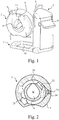
- Fig. 1 shows a general view of one imaging apparatus according to the invention.
- the basic structure of the apparatus includes a support construction (1) which supports a substantially ring-shaped structure (2) within which imaging means (21, 22) of the apparatus are located and which is also referred to as an O-arm in this context.
- This O-arm (2) is arranged with an examination opening (4) within which an anatomy to be imaged is positioned.
- Fig. 1 further shows a patient support rail (5) arranged to the support construction (1), a user interface (6) being in functional connection with a control system of the apparatus, a possibly detachably attached pedestal or base part (7) projecting substantially in the direction of the O-arm, and a positioning support (8) arranged to the examination opening (4).
- a display screen (11) is arranged substantially on the surface of the ring-shaped structure (2), at its upper edge.
- Mounting of the structure (2) supporting the imaging means to the support construction (1) can be arranged to enable adjustment of the height position of the O-arm (2). Furthermore, this O-arm (2) can be arranged to be turnable in at least one direction for at least 90 degrees from the vertical position shown in Fig. 1 to the horizontal position.
- the control of these manoeuvres can be arranged implementable aside from the user interface (6) being connected with the control system of the apparatus also by means of a joy stick (9) arranged into connection with the O-arm (2) and/or the support frame (1) .
- an outer cover (3) of the O-arm (2) forms for its prevailing part a circle which yet comprises a sector where the distance from the centre of said circle to the edges of the outer cover (3) is smaller than the radius of that portion being circular for its prevailing part.
- the part in said sector being cut off the O-arm (2) is evenly curved in the opposite direction with respect to the arch of the circle of the prevailing portion of the outer cover (3), but this cut part can also be of some other shape, such as wedge-shaped, rectangular, straight or even curved in the same direction as the portion of the arch of the outer cover (3) substantially of the shape of a circle.
- the examination opening (4) can be driven closer to the floor level as compared to an O-arm (2) not comprising such a cut.
- the imaging apparatus is provided with a possibility to adjust the height position of the O-arm (2) and to turn the O-arm (2) to a position where the central axis of the O-arm (2) is substantially vertical, one may use the apparatus to image the patient in a standing position, too. Then, said cut arranged to the O-arm (2) makes it easier for the patient to step into the examination opening (4) and out of the examination opening as the length of the step one needs to take over the 'doorstep' formed by the O-arm (2) will be shorter.
- the examination opening (4) is implemented only for its prevailing part substantially as a circle.
- a sector has been arranged to the examination opening (4) which forms an extension to the circle. That is, the examination opening (4) is provided with a sector in the area of which the distance of the edge of the examination opening (4) from the centre of the circular portion of the examination opening (4) (or from the central axis of the O-arm (2)) is longer than the radius of the circular portion of the examination opening (4).
- Such design of the examination opening (4) is preferable e.g.
- the examination opening (4) is substantially of the shape of a droplet, i.e. the shape of its extension is substantially an equilateral triangle having a truncated apex, but said extension can naturally be of some other shape as well.
- the imaging means i.e. a source of radiation (21) and a receiver of image information (22), are arranged within the substantially ring-shaped structure (2) supporting the imaging means and as movable along a curved path within said structure, substantially on opposite sides of the examination opening (4), whereby the distance between the edge of the examination opening (4) and the outer cover (3) of the O-arm (2) (or the radial dimension of the ring of the O-arm) must naturally be arranged of adequate size to enable said paths.
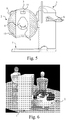
- FIG. 2 shows a possible embodiment of the invention which includes an ring-shaped support part (20) arranged within the O-arm (2), whereto substantially on opposite sides from each other are arranged the source of radiation (21) and the receiver of image information (22).
- the support part (20) is arranged rotatable within the structure (2) supporting the imaging means by means of an actuator (23) and a transmission belt (24).
- the source of radiation (21) and the receiver of image information (22) are arranged movable within substantially ring-shaped structure (2) supporting the imaging means with respect to a centre of rotation such that the source of radiation (21) (the focus of the source of radiation) moves at a different distance from said centre of rotation than the receiver of image information (22).
- the source of radiation (21) is attached on the outer circumference of the ring-shaped support part (20) whereby, when rotating the support part (20), the focus of the source of radiation (21) moves farther from said centre of rotation than the receiver of image information (22) attached on the side of the inner circumference of the support part (20).
- Figs. 3 - 5 show how the apparatus is arranged with at least one padding element (15) on at least one such point which, depending on the imaging mode in question, the patient can touch, lean on, sit on or step on either when positioning oneself to be imaged, in connection with the actual patient positioning and/or during the actual imaging.
- Such padding element (15) can be arranged to the structure (2) supporting the imaging means (21, 22) either to cover substantially whole of that surface of the structure supporting the imaging means (2) from the direction of which the patient steps or positions oneself for imaging into said structure (2) supporting the imaging means (21, 22), or at least part of it.
- the area where there is no padding can be arranged to be some area within the upper section of that surface.
- a display screen (11) can be arranged through which the patient can be shown various information relating to the imaging event.
- the area without the padding (15) can also be arranged on the lower portion of the aforesaid area, as well as at the immediate proximity of the examination opening (4) of the apparatus.
- a padding element (15) can also be arranged on the surface of the support construction (1) the normal of which points towards the structure (2) supporting the imaging means (21, 22).
- At least one padding element (15) is arranged detachably attached.
- the padding (15) wears out and gets dirty during use so that when being detachable, it is easier to clean and be replaced with a new one and in case there are different paddings (15) to choose from, the appearance of the apparatus can be personified as one happens at a given time wish.
- the padding improves patient comfort by offering a more pleasant surface for touch and support, which is nice to available considering the different operational states of the apparatus. It is preferable to arrange the padding (15) specifically on the area of the surface of the support structure (2) supporting the imaging means (21, 22), as in connection with several of the imaging modes the apparatus according to the invention offers, it is specifically that surface from where the patient can look for support in order to better remain stationary during an exposure, which lasts a considerable time.
- Fig. 6 one leg of the patient is being imaged at a standing position, whereupon the padding (15) according to the invention offers a comfortable knee-support for the other leg to facilitate standing still.
- the padding (15) according to the invention offers a comfortable knee-support for the other leg to facilitate standing still.
- the patient's arm is being imaged and as a consequence, the patient is in a slightly awkward position but, remaining in that posture is substantially facilitated by the fact that the patient can lean on to the supportive padding (15) with his/her shoulder and/or head.
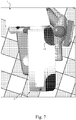
- the range of movement of the imaging means is implemented unlike in some prior-art apparatuses of similar type, i.e. by arranging the source of radiation (21) and the receiver of image information (22) movable along a curved path substantially on opposite sides of the examination opening (4) for a shorter distance than 360 degrees.
- This distance is referred to in the context of this specification as an angle of rotation, and preferably it is arranged to be somewhat larger than 180 degrees but then substantially smaller than 360 degrees, such as of the order of 210 +/- 20 degrees.
- arranging the imaging means (21, 22) to be movable at different distances from the centre of rotation may preferably be implemented particularly in an arrangement comprising the above-described cut in the O-arm (2) and extension in the examination opening (4).
- the range of manoeuvring of the source of radiation (21) can be arranged not to extend to that sector of the O-arm in which the outer cover (3) has been cut like described above and, on the other hand, the range of manoeuvring of the receiver of image information (22) not to extend to that sector of the O-arm (2) in which is arranged an extension of the examination opening (4) as described above.
- the apparatus can be implemented as shown in Fig. 3 such that the source of radiation (21) arranged to move farther from the centre of rotation is able to move outside the extension of the examination opening (4) and the receiver of image information (22), again, inside the cut arranged to the outer cover (3) of the O-arm (2).
- such embodiment of the invention enables a structure where, e.g. considering imaging of extremities, due to the extension arranged to the examination opening (4) it is possible to implement the diameter of the circular portion of the examination opening (4) smaller than would be possible without the extension sector and, further, it is possible to arrange the cut to the outer cover (3) of the O-arm (2) which facilitates several positioning procedures of a patient.
- Such an embodiment of the invention is implementable as a compact structure and it enables realizing both the examination opening (4) and the outer dimensions of the whole O-arm (2) smaller than would otherwise be possible.
- the extension arranged to the examination opening (4) facilitates e.g. positioning of a plastered leg to the examination opening.
- Placing the anatomy to be imaged to the examination opening (4) can be further facilitated by arranging the patient positioning support (8) arranged in connection with the examination opening (4) movable or detachably attached such that it is both positionable to a desired location within the examination opening (4) for imaging and positionable or transferrable to a place where it impedes patient positioning as little as possible.
- the purpose of such patient positioning support (8) is to assist positioning of the anatomy being imaged to a desired point with respect to the O-arm (2).
- the patient positioning support (8) comprises a concave structure whereto an upper or a lower extremity can be positioned for the duration of the imaging.
- the angle of rotation of the imaging means (21, 22) described above is sufficient in cone-beam tomography, in which the beam generated by the source of radiation (21) is arranged to be limited to a true two-dimensional beam and the receiver of image information (22), again, of its form and dimensions at least such that it covers said two-dimensional beam.
- such beam can also be arranged to be limited to more than one size and/or shape, whereby the receiver of image information (22) must naturally be arranged either to cover all possible beam sizes and shapes or it must be arranged changeable.
- the patient support rail (5) of the imaging apparatus shown in Fig. 1 is preferably arranged to extend from top of the support construction (1) substantially to at least one side of the support construction, especially to a side from the direction of which the patient is at least primarily thought to station oneself for imaging - i.e. preferably to the side in the direction of which the cut of the outer cover (3) of the O-arm (2) is arranged to be turned.
- the patient support rail (5) especially facilitates imaging in standing position, i.e. imagings where the O-arm (2) is turned into a position where its central axis is in the vertical orientation, when the patient can take support for himself/herself from the rail (5) when standing inside the O-arm (2) as well as when stepping in and out of it.
- the patient support rail (5) extends to at least one such side of the support construction (1) in the direction of which the cut sector arranged to the O-arm (2) is arranged to be turned.
- the preferable embodiment of the invention described above can be implemented as a relatively compact structure and, for achieving many of the advantages described above, as a structure where the radius of the prevailing portion of the examination opening (4) being of the shape of an arch of a circle is of the order of 15 cm or slightly more and, on the other hand, the radius of the prevailing portion of the O-arm (2) of the shape of an arch of a circle is of the order of 50 cm or even less.
- the distance of the focus of the source of radiation (21) from the centre of rotation of the imaging means (21, 22) can preferably be arranged e.g. for about 390 mm and that of the receiver of image information for about 190 mm.
- the apparatus Since the apparatus is designed to enable imaging of extremities in several different positions, it means in practice that there are several ways to bring an extremity to the imaging area, and to position oneself to be imaged.
- the ways according to the invention and its preferable embodiments to arrange the padding to the apparatus assist in realizing a successful imaging event when facilitating keeping especially the anatomy to be imaged stationary during an exposure.
Landscapes
- Health & Medical Sciences (AREA)
- Life Sciences & Earth Sciences (AREA)
- Engineering & Computer Science (AREA)
- Medical Informatics (AREA)
- Radiology & Medical Imaging (AREA)
- Molecular Biology (AREA)
- Biophysics (AREA)
- Nuclear Medicine, Radiotherapy & Molecular Imaging (AREA)
- Optics & Photonics (AREA)
- Pathology (AREA)
- Physics & Mathematics (AREA)
- Biomedical Technology (AREA)
- Heart & Thoracic Surgery (AREA)
- High Energy & Nuclear Physics (AREA)
- Surgery (AREA)
- Animal Behavior & Ethology (AREA)
- General Health & Medical Sciences (AREA)
- Public Health (AREA)
- Veterinary Medicine (AREA)
- Pulmonology (AREA)
- Theoretical Computer Science (AREA)
- Apparatus For Radiation Diagnosis (AREA)
Claims (12)
- Appareil d'imagerie médicale par tomographie informatisée destiné à présenter en images des extrémités, lequel appareil inclut- une construction de support (1) qui est agencée pour supporter une structure sensiblement annulaire (2) supportant des moyens d'imagerie, lesquels moyens d'imagerie incluent une source de rayonnement (21) et un récepteur d'informations d'image (22), lesquels moyens d'imagerie sont agencés à l'intérieur de ladite structure sensiblement annulaire (2) supportant les moyens d'imagerie sensiblement sur des côtés opposés l'un à l'autre et mobiles à l'intérieur de ladite structure annulaire (2) supportant les moyens d'imagerie (21, 22),- lequel appareil inclut dans ladite structure annulaire (2) supportant les moyens d'imagerie une ouverture d'examen (4) dans lequel l'objet à prendre en image est positionnable pour l'imagerie,- et dans lequel appareil, ladite structure sensiblement annulaire (2) supportant les moyens d'imagerie est agencée mobile par rapport à ladite construction de support (1) au moins dans la direction verticale, et, de l'autre côté, rotative par rapport à un axe sensiblement parallèle à la diagonale horizontale d'une section transversale radiale de ladite structure annulaire (2) supportant les moyens d'imagerie (21, 22),au moins un élément de rembourrage (15) est agencé sur ladite structure sensiblement annulaire (2) supportant les moyens d'imagerie (21, 22) de l'appareil, à au moins un tel point sur lequel le patient peut, en fonction du mode d'imagerie en question, toucher, s'appuyer, s'agenouiller, s'asseoir ou marcher dessus lorsqu'il se place lui-même pour être pris en image, en relation avec le positionnement de patient effectif et/ou pendant l'imagerie effective.
dans lequel - Appareil d'imagerie selon la revendication 1, caractérisé en ce que ledit au moins un élément de rembourrage (15) est agencé pour couvrir sensiblement entièrement cette surface de la structure annulaire (2) supportant les moyens d'imagerie (21, 22) de la direction de laquelle le patient entre ou se place lui-même pour être pris en image à l'intérieur de ladite structure annulaire (2) supportant les moyens d'imagerie (21, 22).
- Appareil d'imagerie selon la revendication 1 ou 2, caractérisé en ce que ledit au moins un élément de rembourrage (15) est agencé pour couvrir cette surface de la structure annulaire (2) supportant les moyens d'imagerie (21, 22) de la direction de laquelle le patient entre ou se place lui-même pour être pris en image à l'intérieur de ladite structure annulaire (2) supportant les moyens d'imagerie (21, 22) sinon entièrement mais, étant donné la structure annulaire (2) supportant les moyens d'imagerie (21, 22) à sa position verticale, une zone est agencée à l'intérieur de la section supérieure de cette surface où il n'y a pas de rembourrage.
- Appareil d'imagerie selon la revendication 3, caractérisé en ce qu'une zone sans rembourrage est également agencée au niveau de la portion inférieure ladite surface.
- Appareil d'imagerie selon l'une quelconque des revendications 1 à 4, caractérisé en ce qu'au moins un élément de rembourrage (15) est agencé sur la surface de la construction de support (1) de l'appareil dont la normale est dirigée vers la structure annulaire (2) supportant les moyens d'imagerie (21, 22).
- Appareil d'imagerie selon l'une quelconque des revendications 1 à 5, caractérisé en ce que ledit au moins un élément de rembourrage (15) est agencé sur l'appareil fixé de manière amovible.
- Appareil d'imagerie selon l'une quelconque des revendications 1 à 6, caractérisé en ce que dans la zone de la surface supportant les moyens d'imagerie (21, 22), une zone sans le rembourrage (15) est agencée, et à l'intérieur d'une telle zone un écran d'affichage (11) est agencé.
- Appareil d'imagerie selon l'une quelconque des revendications 1 à 7, caractérisé en ce que lesdits source de rayonnement (21) et récepteur d'informations d'image (22) sont agencés mobiles à l'intérieur de ladite structure sensiblement annulaire (2) supportant les moyens d'imagerie (21, 22) par rapport à un centre de rotation pour un angle de rotation qui est supérieur à 180 degrés mais sensiblement inférieur à 360 degrés, tel qu'environ 210 +/- 20 degrés.
- Appareil d'imagerie selon l'une quelconque des revendications 1 à 8, caractérisé en ce que lesdits source de rayonnement (21) et récepteur d'informations d'image (22) sont agencés mobiles à l'intérieur de ladite structure sensiblement annulaire (2) supportant les moyens d'imagerie (21, 22) par rapport à un centre de rotation de sorte que la source de rayonnement (21) se déplace à une distance différente dudit centre de rotation que le récepteur d'informations d'image (22).
- Appareil d'imagerie selon l'une quelconque des revendications 1 à 9, caractérisé en ce qu'à l'intérieur de ladite structure annulaire (2) supportant les moyens d'imagerie (21, 22), une partie de support sensiblement annulaire (20) est agencée, lesdits source de rayonnement (21) et récepteur d'informations d'image (22) sont fixés sur cette partie de support (20) et ladite partie de support (20) est agencée de manière rotative à l'intérieur de la structure (2) supportant les moyens d'imagerie (21, 22).
- Appareil d'imagerie selon l'une quelconque des revendications 1 à 10, caractérisé en ce qu'un faisceau généré par ladite source de rayonnement (21) est agencé pour être limitée par un vrai faisceau bidimensionnel et, à nouveau, le récepteur d'informations d'image (22) pour ses formes et dimensions au moins de telle sorte qu'il couvre ledit faisceau bidimensionnel.
- Appareil d'imagerie selon l'une quelconque des revendications 1 à 11, caractérisé en ce que le rayon de la portion dominante de ladite ouverture d'examen (4) qui est sensiblement de la forme d'un arc de cercle est de l'ordre de 15 cm ou un peu plus, le rayon de la portion dominante de ladite structure annulaire (2) supportant les moyens d'imagerie (21, 22) qui est sensiblement de la forme d'un arc de cercle est de l'ordre de 50 cm ou moins, et/ou que la distance du foyer de la source de rayonnement (21) du centre de rotation des moyens d'imagerie (21, 22) est d'environ 390 mm et la distance du récepteur d'informations d'image (22) du centre de rotation des moyens d'imagerie (21, 22) est d'environ 190 mm.
Applications Claiming Priority (3)
| Application Number | Priority Date | Filing Date | Title |
|---|---|---|---|
| FI20100180A FI125531B (fi) | 2010-04-29 | 2010-04-29 | Lääketieteellinen röntgenkuvauslaitteisto |
| FI20100335A FI20100335A (fi) | 2010-04-29 | 2010-09-30 | Lääketieteellinen tietokonetomografiakuvauslaitteisto raajojen kuvantamiseen |
| PCT/FI2011/050389 WO2011135188A2 (fr) | 2010-04-29 | 2011-04-28 | Appareil d'imagerie médicale par tomographie informatisée, destiné à présenter en image des extrémités |
Publications (3)
| Publication Number | Publication Date |
|---|---|
| EP2595540A2 EP2595540A2 (fr) | 2013-05-29 |
| EP2595540A4 EP2595540A4 (fr) | 2015-04-22 |
| EP2595540B1 true EP2595540B1 (fr) | 2018-10-03 |
Family
ID=42133180
Family Applications (3)
| Application Number | Title | Priority Date | Filing Date |
|---|---|---|---|
| EP11774487.0A Active EP2595540B1 (fr) | 2010-04-29 | 2011-04-28 | Appareil d'imagerie médicale par tomographie informatisée, destiné à présenter en image des extrémités |
| EP11724688.4A Active EP2595536B1 (fr) | 2010-04-29 | 2011-04-28 | Appareil d'imagerie médicale à rayons x |
| EP11774489.6A Active EP2600769B1 (fr) | 2010-04-29 | 2011-04-29 | Appareil d'imagerie médicale par tomographie informatisée |
Family Applications After (2)
| Application Number | Title | Priority Date | Filing Date |
|---|---|---|---|
| EP11724688.4A Active EP2595536B1 (fr) | 2010-04-29 | 2011-04-28 | Appareil d'imagerie médicale à rayons x |
| EP11774489.6A Active EP2600769B1 (fr) | 2010-04-29 | 2011-04-29 | Appareil d'imagerie médicale par tomographie informatisée |
Country Status (8)
| Country | Link |
|---|---|
| US (2) | US8684599B2 (fr) |
| EP (3) | EP2595540B1 (fr) |
| JP (4) | JP5771269B2 (fr) |
| KR (3) | KR101800046B1 (fr) |
| CN (4) | CN102917643A (fr) |
| ES (3) | ES2523927T3 (fr) |
| FI (3) | FI125531B (fr) |
| WO (3) | WO2011135186A1 (fr) |
Families Citing this family (14)
| Publication number | Priority date | Publication date | Assignee | Title |
|---|---|---|---|---|
| FI123379B (fi) * | 2010-04-29 | 2013-03-15 | Planmed Oy | Lääketieteellinen tietokonetomografialaitteisto |
| WO2013158655A1 (fr) * | 2012-04-16 | 2013-10-24 | Neurologica Corp. | Système d'imagerie comportant des repères de cliché montés de manière rigide |
| CN104684480B (zh) * | 2012-09-28 | 2018-06-01 | P治疗有限公司 | 用于提供患者成像的装置和方法 |
| USD743553S1 (en) * | 2013-02-28 | 2015-11-17 | DermSpectra LLC | Imaging booth |
| FI125206B (fi) | 2013-11-29 | 2015-07-15 | Planmed Oy | Anatomian osavolyymien asemointi |
| WO2015092450A1 (fr) | 2013-12-17 | 2015-06-25 | Mediso Orvosi Berendezés Fejlesztö És Szerviz Kft. | Appareil de tomographie |
| JP6525768B2 (ja) * | 2015-06-30 | 2019-06-05 | キヤノン株式会社 | 乳房撮影装置 |
| KR101717433B1 (ko) * | 2015-09-01 | 2017-03-17 | 연세대학교 산학협력단 | 엑스레이 컴퓨터 단층촬영 환경에서 빔 경화현상에 의한 인공물 보정방법 |
| MX2021001799A (es) * | 2018-08-16 | 2021-06-15 | Thai Union Group Public Co Ltd | Sistema de imagenes de multiples vistas y metodos para inspeccion no invasiva en el procesamiento de alimentos. |
| GB2579247A (en) * | 2018-11-28 | 2020-06-17 | Hallmarq Veterinary Imaging Ltd | Apparatus for x-ray CT scanning |
| CN112915401B (zh) * | 2019-12-06 | 2023-04-07 | 医科达(北京)医疗器械有限公司 | 用于放疗设备的监视器 |
| KR102211389B1 (ko) * | 2020-01-08 | 2021-02-03 | (주)웨버인스트루먼트 | 인공지능형 회전방식을 구현하는 3차원 골밀도 및 골연령 측정장치 |
| US11013476B1 (en) | 2020-06-08 | 2021-05-25 | SIMULATE Technologies, LLC | Weightbearing simulation assembly and methods of using the same to image a subject |
| CN113709957B (zh) * | 2021-08-27 | 2022-04-01 | 泛华检测技术有限公司 | 一种小型高能x射线装置及方法 |
Family Cites Families (45)
| Publication number | Priority date | Publication date | Assignee | Title |
|---|---|---|---|---|
| JPH02228946A (ja) * | 1989-03-02 | 1990-09-11 | Toshiba Corp | X線ctスキャナ装置 |
| US5042487A (en) * | 1989-11-13 | 1991-08-27 | Marquardt Mark R | Examination unit including positionable patient chair, examination device and support system |
| US5748696A (en) * | 1993-11-26 | 1998-05-05 | Kabushiki Kaisha Toshiba | Radiation computed tomography apparatus |
| JPH08131430A (ja) * | 1994-11-11 | 1996-05-28 | Hitachi Medical Corp | X線ct装置 |
| US6315445B1 (en) * | 1996-02-21 | 2001-11-13 | Lunar Corporation | Densitometry adapter for compact x-ray fluoroscopy machine |
| DE19834457A1 (de) * | 1998-07-30 | 2000-02-10 | Siemens Ag | Röntgenanordnung |
| DE19943898A1 (de) * | 1999-09-14 | 2001-03-15 | Philips Corp Intellectual Pty | Röntgeneinrichtung |
| US6577702B1 (en) * | 2000-03-06 | 2003-06-10 | Biolucent, Inc. | Device for cushioning of compression surfaces |
| JP4267180B2 (ja) * | 2000-06-07 | 2009-05-27 | 株式会社日立メディコ | X線ct装置 |
| DE10046091C1 (de) * | 2000-09-18 | 2002-01-17 | Siemens Ag | Computertomographiegerät und Verfahren für ein Computertomographiegerät |
| DE10109219B4 (de) * | 2001-02-26 | 2005-07-07 | Siemens Ag | Positioniereinrichtung für bildgebende Diagnosesysteme |
| US6618613B1 (en) * | 2001-05-24 | 2003-09-09 | Koninklijke Philips Electronics, N.V. | Non-axial body computed tomography |
| US7769430B2 (en) | 2001-06-26 | 2010-08-03 | Varian Medical Systems, Inc. | Patient visual instruction techniques for synchronizing breathing with a medical procedure |
| DE10146915B4 (de) | 2001-09-24 | 2005-07-28 | Siemens Ag | Vefahren und Bildgebungsgerät für eine 3D-Untersuchung am Patienten in aufrechter oder teilweise aufrechter Körperhaltung |
| JP4746270B2 (ja) | 2002-02-15 | 2011-08-10 | メドトロニック・ナビゲーション・インコーポレーテッド | 着脱可能部分を有する多次元x線イメージング装置用ガントリ・リング |
| AU2003224711A1 (en) | 2002-03-19 | 2003-10-08 | Breakaway Imaging, Llc | Computer tomograph with a detector following the movement of a pivotable x-ray source |
| JP2005529648A (ja) | 2002-06-11 | 2005-10-06 | ブレークアウェイ・イメージング・エルエルシー | X線画像化装置用の片持ち支持ガントリ・リング |
| DE10232681A1 (de) | 2002-07-18 | 2004-01-29 | Siemens Ag | Verfahren und Vorrichtung zur Positionierung eines Patienten in einem medizinischen Diagnose-oder Therapiegerät |
| DE10232676B4 (de) | 2002-07-18 | 2006-01-19 | Siemens Ag | Verfahren und Vorrichtung zur Positionierung eines Patienten in einem medizinischen Diagnose- oder Therapiegerät |
| US7338207B2 (en) * | 2002-08-21 | 2008-03-04 | Medtronic Navigation, Inc. | Gantry positioning apparatus for X-ray imaging |
| JP2004208954A (ja) * | 2002-12-27 | 2004-07-29 | Ge Medical Systems Global Technology Co Llc | 医療画像診断システム |
| US7388941B2 (en) | 2003-08-07 | 2008-06-17 | Xoran Technologies, Inc. | CT extremity scanner |
| JP4375555B2 (ja) * | 2004-05-14 | 2009-12-02 | 株式会社島津製作所 | X線ct装置 |
| US7315087B2 (en) | 2004-06-23 | 2008-01-01 | Intel Corporation | Angled elongated features for improved alignment process integration |
| US7885703B2 (en) | 2004-09-27 | 2011-02-08 | General Electric Company | System and method for scanning a patient |
| US20060079763A1 (en) | 2004-09-30 | 2006-04-13 | Varian Medical Systems Technologies, Inc. | Backprojected patient multimedia display |
| WO2006119420A1 (fr) * | 2005-05-02 | 2006-11-09 | Xoran Technologies, Inc. | Tomodensitomètre pour les extrémités inférieures |
| MD3155G2 (ro) | 2005-06-20 | 2007-04-30 | Александру ЧЕРБАРЬ | Sigiliu de forţă cu cablu |
| US20070053486A1 (en) * | 2005-08-23 | 2007-03-08 | Zelnik Deborah R | Methods and apparatus for nuclear tomo-cardiology scanning |
| GB2436290B (en) * | 2006-03-21 | 2008-04-23 | Siemens Magnet Technology Ltd | Patient calming arrangements |
| JP5329788B2 (ja) * | 2006-10-11 | 2013-10-30 | 株式会社東芝 | X線コンピュータ断層撮影装置、呼吸指示装置及び医用画像撮影装置 |
| CN101926652B (zh) * | 2006-10-11 | 2016-03-23 | 株式会社东芝 | X射线计算机断层及医用图像摄影装置、呼吸指示装置 |
| JP4228018B2 (ja) | 2007-02-16 | 2009-02-25 | 三菱重工業株式会社 | 医療装置 |
| JP2008278902A (ja) * | 2007-05-08 | 2008-11-20 | Fumiaki Ando | Ct装置及びct検査ユニット |
| US20090080604A1 (en) * | 2007-08-23 | 2009-03-26 | Fischer Medical Technologies, Inc. | Computed tomography breast imaging and biopsy system |
| DE102007045325B4 (de) * | 2007-09-21 | 2014-11-20 | Siemens Aktiengesellschaft | Medizinische Untersuchungsvorrichtung |
| JP5014200B2 (ja) * | 2008-02-29 | 2012-08-29 | 富士フイルム株式会社 | 撮像装置 |
| JP2010046356A (ja) * | 2008-08-22 | 2010-03-04 | Fujifilm Corp | 乳房断層画像撮影装置 |
| DE102008046023B4 (de) * | 2008-09-05 | 2010-06-17 | Siemens Aktiengesellschaft | Tomographieanlage und Verfahren zur Überwachung von Personen |
| US8210745B2 (en) * | 2009-05-04 | 2012-07-03 | John Yorkston | Extremity imaging apparatus for cone beam computed tomography |
| US8348506B2 (en) * | 2009-05-04 | 2013-01-08 | John Yorkston | Extremity imaging apparatus for cone beam computed tomography |
| JP4908568B2 (ja) | 2009-10-20 | 2012-04-04 | 株式会社東芝 | 医用診断装置 |
| FI123378B (fi) * | 2010-04-29 | 2013-03-15 | Planmed Oy | Lääketieteellisen röntgenkuvauslaitteiston tutkimusaukko |
| FI123379B (fi) * | 2010-04-29 | 2013-03-15 | Planmed Oy | Lääketieteellinen tietokonetomografialaitteisto |
| CN103209647B (zh) | 2010-09-24 | 2017-07-14 | 斯博特威尔丁股份有限公司 | 缝线锚钉和用于相对硬组织固定缝线的方法 |
-
2010
- 2010-04-29 FI FI20100180A patent/FI125531B/fi active IP Right Grant
- 2010-09-30 FI FI20100335A patent/FI20100335A/fi not_active Application Discontinuation
- 2010-09-30 FI FI20100336A patent/FI125513B/fi active IP Right Grant
-
2011
- 2011-04-28 CN CN201180027499XA patent/CN102917643A/zh active Pending
- 2011-04-28 ES ES11724688.4T patent/ES2523927T3/es active Active
- 2011-04-28 KR KR1020127031183A patent/KR101800046B1/ko active IP Right Grant
- 2011-04-28 WO PCT/FI2011/050387 patent/WO2011135186A1/fr active Application Filing
- 2011-04-28 ES ES11774487T patent/ES2704224T3/es active Active
- 2011-04-28 EP EP11774487.0A patent/EP2595540B1/fr active Active
- 2011-04-28 CN CN201710572516.7A patent/CN107198537B/zh active Active
- 2011-04-28 KR KR1020127031178A patent/KR101828626B1/ko active IP Right Grant
- 2011-04-28 EP EP11724688.4A patent/EP2595536B1/fr active Active
- 2011-04-28 US US13/643,602 patent/US8684599B2/en active Active
- 2011-04-28 JP JP2013506700A patent/JP5771269B2/ja active Active
- 2011-04-28 WO PCT/FI2011/050389 patent/WO2011135188A2/fr active Application Filing
- 2011-04-28 CN CN201180027511.7A patent/CN102917644B/zh active Active
- 2011-04-28 JP JP2013506698A patent/JP5959504B2/ja active Active
- 2011-04-29 US US13/695,101 patent/US8693619B2/en active Active
- 2011-04-29 JP JP2013506704A patent/JP5827316B2/ja active Active
- 2011-04-29 KR KR1020127031179A patent/KR101800045B1/ko active IP Right Grant
- 2011-04-29 CN CN201180027515.5A patent/CN102933149B/zh active Active
- 2011-04-29 WO PCT/FI2011/050394 patent/WO2011135193A2/fr active Application Filing
- 2011-04-29 EP EP11774489.6A patent/EP2600769B1/fr active Active
- 2011-04-29 ES ES11774489T patent/ES2704249T3/es active Active
-
2016
- 2016-03-17 JP JP2016054509A patent/JP6227036B2/ja active Active
Non-Patent Citations (1)
| Title |
|---|
| None * |
Also Published As
Similar Documents
| Publication | Publication Date | Title |
|---|---|---|
| EP2595540B1 (fr) | Appareil d'imagerie médicale par tomographie informatisée, destiné à présenter en image des extrémités | |
| US8681932B2 (en) | Medical computed tomography imaging apparatus for imaging extremities | |
| US8746974B2 (en) | Medical X-ray imaging apparatus with an examination bore | |
| US8596865B2 (en) | Medical x-ray imaging apparatus with a handlebar for patient support |
Legal Events
| Date | Code | Title | Description |
|---|---|---|---|
| PUAI | Public reference made under article 153(3) epc to a published international application that has entered the european phase |
Free format text: ORIGINAL CODE: 0009012 |
|
| 17P | Request for examination filed |
Effective date: 20130404 |
|
| AK | Designated contracting states |
Kind code of ref document: A2 Designated state(s): AL AT BE BG CH CY CZ DE DK EE ES FI FR GB GR HR HU IE IS IT LI LT LU LV MC MK MT NL NO PL PT RO RS SE SI SK SM TR |
|
| DAX | Request for extension of the european patent (deleted) | ||
| A4 | Supplementary search report drawn up and despatched |
Effective date: 20150325 |
|
| RIC1 | Information provided on ipc code assigned before grant |
Ipc: A61B 6/04 20060101ALI20150319BHEP Ipc: A61B 6/03 20060101AFI20150319BHEP |
|
| GRAP | Despatch of communication of intention to grant a patent |
Free format text: ORIGINAL CODE: EPIDOSNIGR1 |
|
| STAA | Information on the status of an ep patent application or granted ep patent |
Free format text: STATUS: GRANT OF PATENT IS INTENDED |
|
| INTG | Intention to grant announced |
Effective date: 20180416 |
|
| RIN1 | Information on inventor provided before grant (corrected) |
Inventor name: LAUKKANEN, TAPIO |
|
| GRAS | Grant fee paid |
Free format text: ORIGINAL CODE: EPIDOSNIGR3 |
|
| GRAA | (expected) grant |
Free format text: ORIGINAL CODE: 0009210 |
|
| STAA | Information on the status of an ep patent application or granted ep patent |
Free format text: STATUS: THE PATENT HAS BEEN GRANTED |
|
| AK | Designated contracting states |
Kind code of ref document: B1 Designated state(s): AL AT BE BG CH CY CZ DE DK EE ES FI FR GB GR HR HU IE IS IT LI LT LU LV MC MK MT NL NO PL PT RO RS SE SI SK SM TR |
|
| REG | Reference to a national code |
Ref country code: GB Ref legal event code: FG4D |
|
| REG | Reference to a national code |
Ref country code: CH Ref legal event code: EP Ref country code: AT Ref legal event code: REF Ref document number: 1047756 Country of ref document: AT Kind code of ref document: T Effective date: 20181015 |
|
| REG | Reference to a national code |
Ref country code: IE Ref legal event code: FG4D Ref country code: DE Ref legal event code: R096 Ref document number: 602011052580 Country of ref document: DE |
|
| REG | Reference to a national code |
Ref country code: NL Ref legal event code: MP Effective date: 20181003 |
|
| REG | Reference to a national code |
Ref country code: LT Ref legal event code: MG4D |
|
| REG | Reference to a national code |
Ref country code: ES Ref legal event code: FG2A Ref document number: 2704224 Country of ref document: ES Kind code of ref document: T3 Effective date: 20190315 Ref country code: AT Ref legal event code: MK05 Ref document number: 1047756 Country of ref document: AT Kind code of ref document: T Effective date: 20181003 |
|
| PG25 | Lapsed in a contracting state [announced via postgrant information from national office to epo] |
Ref country code: NL Free format text: LAPSE BECAUSE OF FAILURE TO SUBMIT A TRANSLATION OF THE DESCRIPTION OR TO PAY THE FEE WITHIN THE PRESCRIBED TIME-LIMIT Effective date: 20181003 |
|
| PG25 | Lapsed in a contracting state [announced via postgrant information from national office to epo] |
Ref country code: CZ Free format text: LAPSE BECAUSE OF FAILURE TO SUBMIT A TRANSLATION OF THE DESCRIPTION OR TO PAY THE FEE WITHIN THE PRESCRIBED TIME-LIMIT Effective date: 20181003 Ref country code: AT Free format text: LAPSE BECAUSE OF FAILURE TO SUBMIT A TRANSLATION OF THE DESCRIPTION OR TO PAY THE FEE WITHIN THE PRESCRIBED TIME-LIMIT Effective date: 20181003 Ref country code: NO Free format text: LAPSE BECAUSE OF FAILURE TO SUBMIT A TRANSLATION OF THE DESCRIPTION OR TO PAY THE FEE WITHIN THE PRESCRIBED TIME-LIMIT Effective date: 20190103 Ref country code: IS Free format text: LAPSE BECAUSE OF FAILURE TO SUBMIT A TRANSLATION OF THE DESCRIPTION OR TO PAY THE FEE WITHIN THE PRESCRIBED TIME-LIMIT Effective date: 20190203 Ref country code: BG Free format text: LAPSE BECAUSE OF FAILURE TO SUBMIT A TRANSLATION OF THE DESCRIPTION OR TO PAY THE FEE WITHIN THE PRESCRIBED TIME-LIMIT Effective date: 20190103 Ref country code: FI Free format text: LAPSE BECAUSE OF FAILURE TO SUBMIT A TRANSLATION OF THE DESCRIPTION OR TO PAY THE FEE WITHIN THE PRESCRIBED TIME-LIMIT Effective date: 20181003 Ref country code: LT Free format text: LAPSE BECAUSE OF FAILURE TO SUBMIT A TRANSLATION OF THE DESCRIPTION OR TO PAY THE FEE WITHIN THE PRESCRIBED TIME-LIMIT Effective date: 20181003 Ref country code: HR Free format text: LAPSE BECAUSE OF FAILURE TO SUBMIT A TRANSLATION OF THE DESCRIPTION OR TO PAY THE FEE WITHIN THE PRESCRIBED TIME-LIMIT Effective date: 20181003 Ref country code: PL Free format text: LAPSE BECAUSE OF FAILURE TO SUBMIT A TRANSLATION OF THE DESCRIPTION OR TO PAY THE FEE WITHIN THE PRESCRIBED TIME-LIMIT Effective date: 20181003 Ref country code: LV Free format text: LAPSE BECAUSE OF FAILURE TO SUBMIT A TRANSLATION OF THE DESCRIPTION OR TO PAY THE FEE WITHIN THE PRESCRIBED TIME-LIMIT Effective date: 20181003 |
|
| PG25 | Lapsed in a contracting state [announced via postgrant information from national office to epo] |
Ref country code: SE Free format text: LAPSE BECAUSE OF FAILURE TO SUBMIT A TRANSLATION OF THE DESCRIPTION OR TO PAY THE FEE WITHIN THE PRESCRIBED TIME-LIMIT Effective date: 20181003 Ref country code: RS Free format text: LAPSE BECAUSE OF FAILURE TO SUBMIT A TRANSLATION OF THE DESCRIPTION OR TO PAY THE FEE WITHIN THE PRESCRIBED TIME-LIMIT Effective date: 20181003 Ref country code: AL Free format text: LAPSE BECAUSE OF FAILURE TO SUBMIT A TRANSLATION OF THE DESCRIPTION OR TO PAY THE FEE WITHIN THE PRESCRIBED TIME-LIMIT Effective date: 20181003 Ref country code: PT Free format text: LAPSE BECAUSE OF FAILURE TO SUBMIT A TRANSLATION OF THE DESCRIPTION OR TO PAY THE FEE WITHIN THE PRESCRIBED TIME-LIMIT Effective date: 20190203 Ref country code: GR Free format text: LAPSE BECAUSE OF FAILURE TO SUBMIT A TRANSLATION OF THE DESCRIPTION OR TO PAY THE FEE WITHIN THE PRESCRIBED TIME-LIMIT Effective date: 20190104 |
|
| REG | Reference to a national code |
Ref country code: DE Ref legal event code: R097 Ref document number: 602011052580 Country of ref document: DE |
|
| PG25 | Lapsed in a contracting state [announced via postgrant information from national office to epo] |
Ref country code: DK Free format text: LAPSE BECAUSE OF FAILURE TO SUBMIT A TRANSLATION OF THE DESCRIPTION OR TO PAY THE FEE WITHIN THE PRESCRIBED TIME-LIMIT Effective date: 20181003 |
|
| PLBE | No opposition filed within time limit |
Free format text: ORIGINAL CODE: 0009261 |
|
| STAA | Information on the status of an ep patent application or granted ep patent |
Free format text: STATUS: NO OPPOSITION FILED WITHIN TIME LIMIT |
|
| PG25 | Lapsed in a contracting state [announced via postgrant information from national office to epo] |
Ref country code: SK Free format text: LAPSE BECAUSE OF FAILURE TO SUBMIT A TRANSLATION OF THE DESCRIPTION OR TO PAY THE FEE WITHIN THE PRESCRIBED TIME-LIMIT Effective date: 20181003 Ref country code: RO Free format text: LAPSE BECAUSE OF FAILURE TO SUBMIT A TRANSLATION OF THE DESCRIPTION OR TO PAY THE FEE WITHIN THE PRESCRIBED TIME-LIMIT Effective date: 20181003 Ref country code: EE Free format text: LAPSE BECAUSE OF FAILURE TO SUBMIT A TRANSLATION OF THE DESCRIPTION OR TO PAY THE FEE WITHIN THE PRESCRIBED TIME-LIMIT Effective date: 20181003 Ref country code: SM Free format text: LAPSE BECAUSE OF FAILURE TO SUBMIT A TRANSLATION OF THE DESCRIPTION OR TO PAY THE FEE WITHIN THE PRESCRIBED TIME-LIMIT Effective date: 20181003 |
|
| 26N | No opposition filed |
Effective date: 20190704 |
|
| PG25 | Lapsed in a contracting state [announced via postgrant information from national office to epo] |
Ref country code: SI Free format text: LAPSE BECAUSE OF FAILURE TO SUBMIT A TRANSLATION OF THE DESCRIPTION OR TO PAY THE FEE WITHIN THE PRESCRIBED TIME-LIMIT Effective date: 20181003 |
|
| REG | Reference to a national code |
Ref country code: CH Ref legal event code: PL |
|
| REG | Reference to a national code |
Ref country code: BE Ref legal event code: MM Effective date: 20190430 |
|
| GBPC | Gb: european patent ceased through non-payment of renewal fee |
Effective date: 20190428 |
|
| PG25 | Lapsed in a contracting state [announced via postgrant information from national office to epo] |
Ref country code: MC Free format text: LAPSE BECAUSE OF FAILURE TO SUBMIT A TRANSLATION OF THE DESCRIPTION OR TO PAY THE FEE WITHIN THE PRESCRIBED TIME-LIMIT Effective date: 20181003 Ref country code: LU Free format text: LAPSE BECAUSE OF NON-PAYMENT OF DUE FEES Effective date: 20190428 |
|
| PG25 | Lapsed in a contracting state [announced via postgrant information from national office to epo] |
Ref country code: LI Free format text: LAPSE BECAUSE OF NON-PAYMENT OF DUE FEES Effective date: 20190430 Ref country code: GB Free format text: LAPSE BECAUSE OF NON-PAYMENT OF DUE FEES Effective date: 20190428 Ref country code: CH Free format text: LAPSE BECAUSE OF NON-PAYMENT OF DUE FEES Effective date: 20190430 |
|
| PG25 | Lapsed in a contracting state [announced via postgrant information from national office to epo] |
Ref country code: BE Free format text: LAPSE BECAUSE OF NON-PAYMENT OF DUE FEES Effective date: 20190430 |
|
| PG25 | Lapsed in a contracting state [announced via postgrant information from national office to epo] |
Ref country code: TR Free format text: LAPSE BECAUSE OF FAILURE TO SUBMIT A TRANSLATION OF THE DESCRIPTION OR TO PAY THE FEE WITHIN THE PRESCRIBED TIME-LIMIT Effective date: 20181003 |
|
| PG25 | Lapsed in a contracting state [announced via postgrant information from national office to epo] |
Ref country code: IE Free format text: LAPSE BECAUSE OF NON-PAYMENT OF DUE FEES Effective date: 20190428 |
|
| PG25 | Lapsed in a contracting state [announced via postgrant information from national office to epo] |
Ref country code: CY Free format text: LAPSE BECAUSE OF FAILURE TO SUBMIT A TRANSLATION OF THE DESCRIPTION OR TO PAY THE FEE WITHIN THE PRESCRIBED TIME-LIMIT Effective date: 20181003 |
|
| PG25 | Lapsed in a contracting state [announced via postgrant information from national office to epo] |
Ref country code: MT Free format text: LAPSE BECAUSE OF FAILURE TO SUBMIT A TRANSLATION OF THE DESCRIPTION OR TO PAY THE FEE WITHIN THE PRESCRIBED TIME-LIMIT Effective date: 20181003 Ref country code: HU Free format text: LAPSE BECAUSE OF FAILURE TO SUBMIT A TRANSLATION OF THE DESCRIPTION OR TO PAY THE FEE WITHIN THE PRESCRIBED TIME-LIMIT; INVALID AB INITIO Effective date: 20110428 |
|
| PG25 | Lapsed in a contracting state [announced via postgrant information from national office to epo] |
Ref country code: MK Free format text: LAPSE BECAUSE OF FAILURE TO SUBMIT A TRANSLATION OF THE DESCRIPTION OR TO PAY THE FEE WITHIN THE PRESCRIBED TIME-LIMIT Effective date: 20181003 |
|
| PGFP | Annual fee paid to national office [announced via postgrant information from national office to epo] |
Ref country code: IT Payment date: 20230420 Year of fee payment: 13 Ref country code: FR Payment date: 20230420 Year of fee payment: 13 Ref country code: ES Payment date: 20230505 Year of fee payment: 13 Ref country code: DE Payment date: 20230412 Year of fee payment: 13 |