EP2592409A2 - Prüfsystem - Google Patents
Prüfsystem Download PDFInfo
- Publication number
- EP2592409A2 EP2592409A2 EP12007567.6A EP12007567A EP2592409A2 EP 2592409 A2 EP2592409 A2 EP 2592409A2 EP 12007567 A EP12007567 A EP 12007567A EP 2592409 A2 EP2592409 A2 EP 2592409A2
- Authority
- EP
- European Patent Office
- Prior art keywords
- history
- test system
- unit
- time
- operational
- Prior art date
- Legal status (The legal status is an assumption and is not a legal conclusion. Google has not performed a legal analysis and makes no representation as to the accuracy of the status listed.)
- Granted
Links
Images





Classifications
-
- G—PHYSICS
- G01—MEASURING; TESTING
- G01N—INVESTIGATING OR ANALYSING MATERIALS BY DETERMINING THEIR CHEMICAL OR PHYSICAL PROPERTIES
- G01N33/00—Investigating or analysing materials by specific methods not covered by groups G01N1/00 - G01N31/00
- G01N33/0004—Gaseous mixtures, e.g. polluted air
-
- G—PHYSICS
- G01—MEASURING; TESTING
- G01M—TESTING STATIC OR DYNAMIC BALANCE OF MACHINES OR STRUCTURES; TESTING OF STRUCTURES OR APPARATUS, NOT OTHERWISE PROVIDED FOR
- G01M15/00—Testing of engines
- G01M15/04—Testing internal-combustion engines
- G01M15/10—Testing internal-combustion engines by monitoring exhaust gases or combustion flame
- G01M15/102—Testing internal-combustion engines by monitoring exhaust gases or combustion flame by monitoring exhaust gases
-
- G—PHYSICS
- G01—MEASURING; TESTING
- G01M—TESTING STATIC OR DYNAMIC BALANCE OF MACHINES OR STRUCTURES; TESTING OF STRUCTURES OR APPARATUS, NOT OTHERWISE PROVIDED FOR
- G01M17/00—Testing of vehicles
- G01M17/007—Wheeled or endless-tracked vehicles
- G01M17/0072—Wheeled or endless-tracked vehicles the wheels of the vehicle co-operating with rotatable rolls
-
- G—PHYSICS
- G01—MEASURING; TESTING
- G01N—INVESTIGATING OR ANALYSING MATERIALS BY DETERMINING THEIR CHEMICAL OR PHYSICAL PROPERTIES
- G01N33/00—Investigating or analysing materials by specific methods not covered by groups G01N1/00 - G01N31/00
-
- G—PHYSICS
- G01—MEASURING; TESTING
- G01N—INVESTIGATING OR ANALYSING MATERIALS BY DETERMINING THEIR CHEMICAL OR PHYSICAL PROPERTIES
- G01N33/00—Investigating or analysing materials by specific methods not covered by groups G01N1/00 - G01N31/00
- G01N33/0004—Gaseous mixtures, e.g. polluted air
- G01N33/0006—Calibrating gas analysers
-
- G—PHYSICS
- G01—MEASURING; TESTING
- G01N—INVESTIGATING OR ANALYSING MATERIALS BY DETERMINING THEIR CHEMICAL OR PHYSICAL PROPERTIES
- G01N33/00—Investigating or analysing materials by specific methods not covered by groups G01N1/00 - G01N31/00
- G01N33/0004—Gaseous mixtures, e.g. polluted air
- G01N33/0009—General constructional details of gas analysers, e.g. portable test equipment
-
- G—PHYSICS
- G07—CHECKING-DEVICES
- G07C—TIME OR ATTENDANCE REGISTERS; REGISTERING OR INDICATING THE WORKING OF MACHINES; GENERATING RANDOM NUMBERS; VOTING OR LOTTERY APPARATUS; ARRANGEMENTS, SYSTEMS OR APPARATUS FOR CHECKING NOT PROVIDED FOR ELSEWHERE
- G07C5/00—Registering or indicating the working of vehicles
-
- G—PHYSICS
- G07—CHECKING-DEVICES
- G07C—TIME OR ATTENDANCE REGISTERS; REGISTERING OR INDICATING THE WORKING OF MACHINES; GENERATING RANDOM NUMBERS; VOTING OR LOTTERY APPARATUS; ARRANGEMENTS, SYSTEMS OR APPARATUS FOR CHECKING NOT PROVIDED FOR ELSEWHERE
- G07C5/00—Registering or indicating the working of vehicles
- G07C5/006—Indicating maintenance
Definitions
- the present invention relates to a test system for mobile bodies such as vehicles, vessels, and planes, and also for testing components of the mobile bodies, for example, an internal-combustion engine.
- a known conventional automobile test system is configured such that a plurality of measuring apparatuses (measuring devices) are connected to one measurement managing device, and the managing device manages the measuring apparatuses together (Refer to, for example, Patent Literature 1).
- Patent Literature 1 Unexamined Patent Publication No. 2005-49353
- the measuring device operates in various operational modes including an elapsed mode in which an embedded PC is in a conducting state, a stand-by mode in which measurement can be immediately started, a measurement mode, a calibration mode, a purge mode, and a measurement + purge mode.
- the measuring device includes various components such as a valve, a pump, a sensor, and a heater. For this reason, depending on the operational mode of the measuring device, some components actually operate, while other components do not actually operate. Accordingly, even in the operational mode in which some components do not actually operate, when operating periods of the components are uniformly accumulated, the operating periods of the components cannot be accurately accumulated. Further, it has been demanded to manage the timing of operational check such as leak check and purge processing of an exhaust gas flow line constituting a test system such as an exhaust-gas analyzing system.
- the present invention is made in consideration of such problem, and its main object is to acquire operating history of instruments constituting the test system or operational check history of the test system as well as to accumulate the operating period of each component much more accurately than the conventional system.
- a test system is a test system that tests a mobile body such as a vehicle, a vessel or a plane, or instruments used in the mobile body as objects, and is operable by switching among different operational modes, the test system including a history-information acquiring unit for acquiring operating history information indicating operating history including operating time of a component or operational check history information indicating operational check history of operational check, wherein, in accumulating the operating time of the component, the history-information acquiring unit accumulates the operating time of the component only in the predetermined operational mode set for each component.
- one or more testing devices used for testing and a device-managing device communicably connected to the testing devices, the device-managing device managing the testing devices, are further included, an accumulated operating-time calculating unit accumulates the operating time of components of the testing devices, and the device-managing device includes an accepting unit for accepting designation of the component and designation of the predetermined operational mode of the designated component.
- the device-managing device is provided with an accumulated operating-time calculating unit, and the testing device is provided with an accumulated operating-time storing unit for storing accumulated operating time calculated by the accumulated operating-time calculating unit.
- the device-managing device further includes a warning generating unit for generating a real warning when the accumulated operating time reaches lifetime of the component, and a preliminary warning when the accumulated operating time reaches a predetermined time prior to the lifetime.
- a warning generating unit for generating a real warning when the accumulated operating time reaches lifetime of the component, and a preliminary warning when the accumulated operating time reaches a predetermined time prior to the lifetime.
- an accepting unit for accepting designation of the lifetime and/or the predetermined time.
- the testing devices are measuring devices for measuring a state amount of the object, and more specifically, the measuring device is provided in an exhaust path of the internal-combustion engine to measure the exhaust gas flowing through the exhaust path.
- the operating history of the instrument or the operational check history of the test system can be acquired, and furthermore, the user can arbitrarily set the instrument or the operational check, the history of which is to be acquired, to simplify management of the test system.
- the managing device used in the test system according to the present invention includes a display control unit displaying a setting screen for setting an instrument with operating history to be managed among the instruments constituting the test system such as the exhaust-gas analyzing system or setting operational check of the test system with operational check history to be managed, and a history-information acquiring unit for acquiring operating history information indicating the operating history of the instrument set on the setting screen, or operational check history information indicating the operational check history of the operational check set on the setting screen.
- the history-information acquiring unit acquires the operating history information of the instrument set on the setting screen or the operational check history information of the operational check set on the setting screen, the operating history information of the instruments constituting the test system such as the exhaust-gas analyzing system or the operational check history information of the operational check can be managed, and further, the user can arbitrarily set the instrument or operational check to be managed. Therefore, according to the present invention, the user can arbitrarily select the instrument or operational check to be managed and therefore, management of the exhaust-gas analyzing system can be simplified.
- the operating history information includes the accumulated operating time of the instrument, and the operational check history information includes elapsed time from completion of the last operational check. Since the operating history information includes the accumulated operating time, the state of the instruments constituting the test system can be easily recognized, and for example, the usable life and maintenance timing of the instruments can be easily managed. Further, since the operational check history information includes the elapsed time from completion of the last operational check, the timing of next operational check can be estimated.
- the setting screen has an upper limit value input column for setting an upper limit value of the accumulated operating time of the set instrument or the elapsed time of the set operational check
- the test system further includes a time comparing unit for comparing the upper limit value set by the upper limit value input column with the accumulated operating time or elapsed time acquired by the history-information acquiring unit, and an informing unit for informing that the accumulated operating time or the elapsed time exceeds the upper limit value.
- the user since the user merely inputs the upper limit value in the upper limit value input column on the setting screen, thereby having the device automatically compare the upper limit value with the accumulated operating time or the elapsed time, the user does not need to confirm the accumulated operating time or the elapsed time each time, which improves usability.
- the display control unit displays the operating history information or the operational check history information, which is acquired by the history-information acquiring unit, on the setting screen.
- the display control unit displays the operating history information or the operational check history information, which is acquired by the history-information acquiring unit, on the setting screen.
- a test system managing program allows a computer to perform functions of a display control unit for displaying a setting screen for setting an instrument with operating history to be managed among the instruments constituting the test system such as the exhaust-gas analyzing system or for setting operational check of the test system with operational check history to be managed, and a history-information acquiring unit for acquiring operating history information of the instrument set on the setting screen, or operational check history information of the operational check set on the setting screen.
- the present invention thus configured, by accumulating the operating time of each component only in the predetermined operational mode set for each component, the accumulation of the operating period of each component can be performed much more accurately than conventional system.
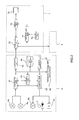
- Fig. 1 schematically shows the whole of a vehicle performance test system 1 in accordance with the first embodiment.
- the vehicle performance test system 1 includes a chassis dynamometer (not shown), an automatic driving device (not shown), a test automatic managing device 6, a plurality of exhaust-gas measuring devices 4, a device-managing device 7 and so on, and can test vehicle performances by putting a vehicle VH into a simulated driving state on the chassis dynamometer and measuring fuel consumption, exhaust-gas ingredients and so on of the vehicle VH.
- An engine as a single item can be tested. Each part will be described below.
- the test automatic managing device 6 has a basic function of setting schedule of a driving test. When the operator performs such schedule setting, the test automatic managing device 6 transmits a command following its regulation to the chassis dynamometer, the automatic driving device, the device-managing device 7 and so on, and controls these components such that a test as regulated is automatically performed.
- test automatic managing device 6 can perform scheduling for each of the device-managing devices 7.
- the exhaust-gas measuring device 4 (hereinafter, may be also referred to as measuring device 4) includes an exhaust-gas ingredient measuring device configured of a set of one or more gas analyzing units as unit instruments and also, for example, a device that performs pre-processing of measuring exhaust-gas ingredients, for example, a constant-volume sampling device.
- plural types of measuring devices 4 are used. Examples include a first measuring device 4 that includes a plurality of gas analyzing units having different measurement principles, a second measuring device 4 as a constant-volume sampling device, a third measuring device 4 as an EGR rate measuring device, and a fourth measuring device 4 as an ultrasonic flow meter.
- the gas analyzing unit include FID that measures THC, and CLD that measures NO x , and an NDIR that measures CO 2 .
- the measuring device 4 measures the amount of ingredients such as HC, NO x , CO, CO 2 of gas sampled from, for example, a predetermined place in an intake and exhaust path of an internal-combustion engine, and can also calculate performance values such as fuel consumption and EGR rate of the instruments constituting the vehicle VH such as engine and catalyst from the measured value. For this reason, each measuring device 4, as shown in Fig. 2 , includes a local computer.
- the local computer physically includes a CPU, a memory, an A/D converter, a communication interface and so on.
- the CPU and peripheral instruments work together according to a program stored in the memory and correct/calibrate an output value from a sensor 4a for detecting predetermined ingredients of exhaust gas, thereby calculating a measured value indicating the concentration of each of the ingredients.
- the local computer includes a calculating unit 41 that calculates a performance value of the instrument from the measured value and a communicating unit 42 that transmits the measured value and the instrument performance value, which are calculated by the calculating unit 41, to the device-managing device 7 according to a predetermined protocol.
- the local computer further includes a control unit 43 that receives a command signal from the device-managing device 7 to control a valve V, a temperature regulating mechanism 4b, and a pump 4c, and controls the various operational modes (elapsed mode, stand-by mode, measurement mode, calibration mode, purge mode) of the exhaust-gas measuring device 4, a calibrating unit 44 that calibrates the sensor 4a, a local accumulating unit (accumulated operating-time storing unit) 45 that is provided in a predetermined area of the memory and successively acquires and accumulates device state information of the measuring device 4 up to now, an accumulated operating-time calculating unit 46 as a history-information acquiring unit, and a warning generating unit 47.
- a control unit 43 that receives a command signal from the device-managing device 7 to control a valve V, a temperature regulating mechanism 4b, and a pump 4c, and controls the various operational modes (elapsed mode, stand-by mode, measurement mode, calibration mode, purge mode) of the exhaust-gas measuring device
- the device-managing device 7 is configured, for example, by installing a predetermined program in a general-purpose computer, and physically includes a CPU, a memory, a display, an input means (keyboard, mouse and the like), and a communication interface.
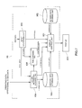
- the CPU and peripheral instruments work together according to the program stored in the memory, resulting in that the device-managing device 7, as shown in Fig. 2 , performs functions of a display unit 72, an accepting unit 73, a managing unit body 74, and a communicating unit 75.
- the device-managing device 7 is provided with a communications port, and the measuring device 4 is intercommunicated with the device-managing device 7 by wired or wireless connection.
- each unit of the device-managing device 7 and their operations will be described.
- the operator performs various operations (for example, piping) related to the measuring device 4 and then, physically connects the measuring device 4 to the device-managing device 7 with a connector cable.
- the operator can properly display a warning screen 8 in a window as shown in Fig. 3 .
- a list of names of the components of the measuring device 4 is displayed on the warning screen 8. For each component, the list includes a name column as well as a life column “Life Time”, an accumulated operating time column “Working Time” indicating the accumulated operating time up to now, and a remaining time column “Status” indicating remaining time to the end of life.
- the remaining time column also indicates below-mentioned warning. Specifically, when the accumulated operating time reaches lifetime of the component, the warning generating unit 47 generates a red real warning. When the accumulated operating time reaches a predetermined preliminary warning period prior to the lifetime, an orange preliminary warning is displayed. In this manner, in this embodiment, two-staged warning display is carried out. On the warning screen, a "Reset" button 82 is operated, for example, after completion of maintenance of each component to reset the accumulated operating time.
- the list on the warning screen 8 is also provided with a "Detail" button 83 as a detail setting button in each row (that is, each component).
- a setting screen 9 for setting the life, the accumulated operating time and so on of each component is displayed in the window.
- the setting screen 9 includes an operational mode designating area 91 and a warning period designating area 92.
- the operational mode designating area 91 includes various columns for designating whether or not the operating time of each component is accumulated when the measuring device 4 is put into each operating mode. Specifically, the columns are a mode designating column 99 for designating the operational mode, a finalizing button 100 for finalizing the designation, and a release button 101 for releasing the designation.
- the operator may click the finalizing button 100 in the state where the stand-by mode is selected and displayed in the mode designating column 99, click the finalizing button 100 in the state where the measurement mode is selected and displayed in the mode designating column 99, and click the release button 101 each time each of the other modes is displayed in the mode designating column 99.
- operating condition information that is, information that time is accumulated only in the stand-by mode and the measurement mode is associated with a component ID and stored in the local accumulating unit 45 of the measuring device 4.
- the accumulated operating-time calculating unit 46 acquires the operating condition information from the local accumulating unit 45, and keeps time by use of a timer not shown only in the operational mode indicated by the operating condition information to accumulate the operating time of the component. The accumulated operating time is successively written into the local accumulating unit 45.
- Hour Meter as the timer may be attached to the measuring device 4, and the accumulated operating-time calculating unit 46 may operate the Hour Meter only in the operational mode, and calculate the accumulated operating time from an output from the Hour Meter.
- the component include a pump, an ozone generator used to measure NO x by use of a CLD meter, and a filter as consumable supplies.
- the warning period designating area 92 includes a display column 102 for displaying the preliminary warning period, buttons 103, 104 for validating/invalidating warning display, and a default button 105 for setting the preliminary warning period to a default value, and the setting can be changed by operator's inputting. When being finalized, these values are associated with the component ID and stored in the local accumulating unit 45.
- the device-managing device can accurately accumulate the operating time of the measuring device 4. Furthermore, the warning generating unit 47 allows the two-staged warning display on the warning screen 8, thereby improving usability.
- the device-managing device 7 includes the accepting unit 73 that accepts designation of the lifetime and/or the predetermined time, the operator can flexibly set the lifetime or the predetermined time.
- the present invention is not necessarily applied to only the first embodiment.
- the present invention can be applied to testing of the engine as a single item, as well as planes, vessels and instruments thereof.
- the test automatic managing device 6 transmits the command following the regulation to the chassis dynamometer, the automatic driving device, and the device-managing device 7 to control these components such that the test can be automatically performed as scheduled.
- the device-managing device 7 may transmit the command following the regulation to each measuring device 4, and for example, the local computer built in the measuring device 4 may transmit the command following the regulation to another measuring device 4.
- the setting screen 9 is displayed on a display 7a of the device-managing device 7 in the above-mentioned embodiment, the present invention is not limited to this.
- the setting screen 9 may be displayed on a display of the test automatic managing device 6.
- warning screen 8 is displayed on the display 7a of the device-managing device 7 in the above-mentioned embodiment, the present invention is not limited to this.
- the warning screen 8 may be displayed on the display of the test automatic managing device 6, or each measuring device 4 may be provided with a blinking lamp, and blinking of the lamp may be a warning that can be recognized by the operator.
- the accumulated operating-time storing unit is provided in the measuring device 4 in the above-mentioned embodiment, the present invention is not limited to this.
- the accumulated operating-time storing unit may be provided in the device-managing device 7. However, in this case, it is needed to associate the accumulated operating time with the identification ID of the measuring device 4 such that the measuring device 4 can be identified in the device-managing device 7, and to store them in the accumulated operating-time storing unit.
- test system An exhaust-gas analyzing system (test system) in accordance with a second embodiment of the present invention will be described below with reference to drawings.
- An exhaust-gas analyzing system X100 in the second embodiment serves to measure exhaust gas of a vehicle V in a housing called a test cell, and as shown in Fig. 5 illustrating its entire configuration, includes a chassis dynamo device X1 on which the vehicle V is placed as a sample, a first exhaust-gas analyzing device X2 and a second analyzing device X3 that analyze various ingredients contained in the exhaust gas from an engine of the vehicle V, an exhaust-gas flow line L that leads the exhaust gas from the engine to the first exhaust-gas analyzing device X2 and the second analyzing device X3, and a central information processor X4 that receives/transmits data between a dynamo controller (not shown) for controlling the chassis dynamo device X1 and each of the exhaust-gas analyzing devices X2, X3.
- a dynamo controller not shown
- the exhaust-gas analyzing system X100 further includes an automatic driving mechanism that is installed in a driver's seat of the vehicle V and has a driving arm for mechanically driving an accelerator, a brake, a shift lever, a steering wheel and so on, and an automatic driving mechanism controller that controls the automatic driving mechanism (both are not shown), and operates the driving arm according to an external control signal, thereby having the vehicle V automatically travel on the chassis dynamo device X1.
- an automatic driving mechanism that is installed in a driver's seat of the vehicle V and has a driving arm for mechanically driving an accelerator, a brake, a shift lever, a steering wheel and so on
- an automatic driving mechanism controller that controls the automatic driving mechanism (both are not shown), and operates the driving arm according to an external control signal, thereby having the vehicle V automatically travel on the chassis dynamo device X1.
- the exhaust-gas flow line L includes a first exhaust-gas flow line L1 that leads the exhaust gas from the engine to the first exhaust-gas analyzing device X2 without diluting the exhaust gas, and a second exhaust-gas flow line L2 that dilutes the exhaust gas from the engine, which passes a catalyst (CAT) and is discharged from an exhaust pipe (tail pipe), through a diluting tunnel L21 and leads the diluted gas to the second exhaust-gas analyzing device X3.
- CAT catalyst
- the first exhaust-gas flow line L1 has an introduction port P1 that introduces the exhaust gas from the engine, one end of which is provided in the exhaust pipe, and the other end of which is connected to a connection port (not shown) of the first exhaust-gas analyzing device X2.
- the line is a direct sampling line that directly samples the engine exhaust gas.
- the second exhaust-gas flow line L2 includes the diluting tunnel L21 that is connected to the exhaust pipe of the vehicle V and dilutes the engine exhaust gas with air, and a diluting sampling line L22 having an introduction port P2 that introduces diluted exhaust gas, one end of which is provided in the diluting tunnel L21 and the other end of which is connected to a connection port (not shown) of the second exhaust-gas analyzing device X3.
- the first exhaust-gas analyzing device X2 is a measuring instrument that includes a plurality of gas analyzers having different measurement principles and can continuously measure each of ingredients such as CO, CO 2 , O 2 , HC, THC, CH 4 , NO, NO x contained in the engine exhaust gas.
- the first exhaust-gas analyzing device X2 has an infrared-ray gas analyzer using a nondispersive infrared method (NDIR) of measuring the concentration of CO, CO 2 , HC, and NO, an NO x meter using chemical luminescence method (CLD) of measuring the concentration of NO x , an O 2 meter using a pressure magnetic method (PMD) of measuring the concentration of O 2 , a THC meter using a heated hydrogen flame ionization detecting method (HFID) of measuring the concentration of THC, and a CH 4 meter using a gas chromatograph/hydrogen ionization detector (GC-FID) of measuring the concentration of CH 4 .
- NDIR nondispersive infrared method
- CLD chemical luminescence method
- PMD pressure magnetic method
- HFID heated hydrogen flame ionization detecting method
- GC-FID gas chromatograph/hydrogen ionization detector
- the first exhaust-gas analyzing device X2 includes a computer system configured of a CPU, a memory and so on, and performs a function of communicating a control signal, data and so on with the outside.
- the second exhaust-gas analyzing device X3 is a measuring instrument that includes a plurality of gas analyzers having different measurement principles and can continuously measure each of ingredients such as THC, CH 4 , NO contained in the diluted exhaust gas.
- the second exhaust-gas analyzing device X3 has an infrared-ray gas analyzer using the nondispersive infrared method (NDIR) of measuring the concentration of NO, a THC meter using the heated hydrogen flame ionization detecting method (HFID) of measuring the concentration of THC, and a CH 4 meter using the gas chromatograph/hydrogen ionization detector (GC-FID) of measuring the concentration of CH 4 .
- NDIR nondispersive infrared method
- HFID heated hydrogen flame ionization detecting method
- GC-FID gas chromatograph/hydrogen ionization detector
- the second exhaust-gas analyzing device X3 includes a computer system configured of a CPU, a memory and so on, and performs a function of communicating a control signal, data and so on with the outside.
- the central information processor X4 is, for example, computer system provided with a CPU, a memory, a communication interface, a display, input means and so on, and has a server function.
- the central information processor X4 is configured to receive/transmit data from/to each controller and the first and second exhaust-gas analyzing devices X2, X3 via a network NT such as LAN to perform overall control of each controller and the first and second exhaust-gas analyzing devices X2, X3, and data management.
- the chassis dynamo device X1 and the automatic driving mechanism are controlled together via their controllers, the vehicle V (automobile) travels in a desired manner, and the first and second exhaust-gas analyzing devices X2, X3 operate to automatically measure exhaust gas data. Further, the exhaust gas data and driving data are managed by the central information processor X4 in an integrated fashion.
- each controller and the first and second exhaust-gas analyzing devices X2, X3 need not to be physically separated and dispersed, and as a matter of course, may be integrated partially or wholly.
- the first exhaust-gas analyzing device X2 includes an exhaust gas analysis managing device X5 for managing history information of the exhaust-gas analyzing system X100.
- the managing device X5 is, as shown in Fig. 6 , a general-purpose or dedicated computer including a CPU (X501), a memory X502, an input/output interface X503, an AD converter X504, and input means X505, and the CPU (X501) and the peripheral instruments work together according to a predetermined program stored in a predetermined area of the memory X502, thereby having a display control unit X51, a screen data storing unit X52, input accepting unit X53, history-information acquiring unit X54, a history data storing unit X55, a time comparing unit X56 perform their function as shown in Fig. 7 .
- the managing device X5 uses a display X21 of the first exhaust-gas analyzing device X2, but may have a dedicated display other than the display X21.
- the input accepting unit X53 acquires a mode selecting signal and transmits the signal to the display control unit X51.
- the display control unit X51 acquires setting screen data indicating a processing setting screen W1 shown in Fig. 8 to Fig. 10 from the screen data storing unit X52, and displays the setting screen W1 on the display X21.
- Fig. 8 to Fig. 10 shows the same setting screen W1, but show different display areas varied by use of a scroll bar W11 displayed on a side in the screen.
- the setting screen W1 is a screen for setting the instrument and the operational check, which are to be managed, among the plurality of instruments constituting the exhaust-gas analyzing system X100 and a plurality of items of operational check.
- the setting screen W1 has item input columns ("Item Name") S1 for inputting the instrument items indicating the instruments constituting the exhaust-gas analyzing system X100 or operational check items indicating the operational check of the exhaust-gas analyzing system X100.
- the instrument items include the CPU and a tubing pump of the exhaust-gas analyzing devices X2, X3 constituting the exhaust-gas analyzing system X100, and as long as operational data that indicates instrument operation/stop can be acquired from the instrument or the controller controlling the instrument, any instrument item can be set.
- Examples of the operational check items include basic performance check, linearization check, response check, analyzer check, CO meter interference check, CO 2 meter interference check, THC meter CH 4 meter relative response/O 2 interference check, non-methane cutter efficiency check, NO x converter efficiency check, leak check, sample line HC hang-up check, NO x meter quenching check, HC relative response, and as long as operational check data indicating the presence/absence of implementation of the operational check can be acquired, any operational check can be set.
- items corresponding to the regulation prescribed in the U.S. EPA 40 CFR Part 1065
- the setting screen W1 further includes a setup button ("Item Setup") B1 for setting the instrument item or the operational check item inputted to the item input columns S1, history information display columns (time display columns, "Elapsed") S2 for displaying the operating history (accumulated operating time in this embodiment) of the instruments inputted to the item input columns S1 or the operational check history (elapsed time from completion of the last operational check in this embodiment) of the operational check inputted to the item input columns S1, upper limit value input columns (“Period”) S3 for inputting upper limit values (warning set values) of the operating time of the instruments inputted to the item input columns S1 or upper limit values (warning set values) of the elapsed time of the operational check items inputted to the item input columns S1, warning selecting buttons ("Warning") B2 for selecting whether or not a warning is issued when the operating time or the elapsed time exceeds the upper limit value inputted to the upper limit value input column S3, unit selecting buttons ("Unit”) B3 for selecting time unit of the upper limit value
- the setting screen W1 further includes a line switching button ("Line”) B6 for switching display such that the setting can be made for each exhaust gas flow line (for example, the direct sampling line L1, the diluting sampling line L22, or both (“Common")).
- the setting screen W1 further includes a finalizing button (“OK”) B7 for finalizing the setting inputted to the setting screen W1, and a closing button (“CANCEL”) B8 for stopping setting input and closing the setting screen W1.
- linearization check (Linearization)
- CO 2 meter interference check (CO 2 Interference)
- NO x converter efficiency check (“NO x Efficiency”)
- leak check (Leak Check)
- sample line HC hang-up check (“HC Hangup Check)
- NO x meter quenching check (“CLA Quenching Check)
- HC relative response (“HC Relative Response”
- CO 2 meter interference check (CO 2 Interference [CFR])
- NO x converter efficiency check (“NO x Efficiency [CFR]”
- leak check (“Leak Check [CFR]”
- sample line HC hang-up check (“HC Hangup Check [CFR]”
- NO x meter quenching check (“CLA Quenching Check [CFR]”
- HC relative response (“HC Relative Response [CFR]”
- O 2 meter interference check (O 2 Interference Check [CFR]”) each according to regulation (CFR) of U.S. EPA, tubing pump of the exhaust-
- the setting screen W1 includes the plurality of item input columns S1 for inputting a plurality of user-set items other than the initial set items, and the user selects the setup button B1, thereby arbitrarily inputting an item in the item input column S1.
- "User Definition" is displayed in these item input columns S1.
- the user inputs a numerical value in the upper limit value input columns S3 by use of the input means X505 such as a keyboard or a mouse to set the upper limit value.
- the input means X505 such as a keyboard or a mouse to set the upper limit value.
- "Hours” is displayed in the unit selecting buttons B3, and “Hours” can be changed to "Days” by clicking the unit selecting buttons B3. At this time, "Days" is displayed in the unit selecting buttons B3.
- the user can switch the mode of acquiring the history information among the stand-by mode ("Stand-by") prior to measurement of the exhaust gas, the exhaust gas measurement mode (“Measure”), the exhaust gas measurement and purge mode (“Measure & Purge”) and all mode ("Always”) by clicking the mode selecting buttons B4 by use of the input means X505 such as the keyboard or the mouse.
- the mode selecting buttons B4 By allowing the history information to be acquired in the stand-by mode, in the gas analyzer in which gas flows during stand-by (for example, in an FID meter, N 2 gas flows), the timing of maintenance can be determined in consideration of the stand-by state.
- the history-information acquiring unit X54 acquires the operating history information of the instruments or the operational check history information of the operational check. Specifically, history-information acquiring unit X54 acquires the operational data indicating the instrument operational information from the instruments or controller for the instruments, management of which is set, and accumulates the operating time of each instrument from the operational data. The history-information acquiring unit X54 acquires the operational check data indicating presence/absence of implementation of the operational check, management of which is set, from the instruments to be checked or the controllers for the instruments, and measures the elapsed time from the last operational check on the basis of the operational check data.
- the history-information acquiring unit X54 stores the history data of the accumulated operating time or the elapsed time thus calculated in the history data storing unit X55, and outputs the history data to the time comparing unit X56 and the display control unit X51.
- the display control unit X51 displays the accumulated operating time data or the elapsed time data (history data) obtained from the history information acquiring unit X54 in the history information display columns (time display columns) S2 on the setting screen W1.
- the time comparing unit X56 compares each upper limit value obtained from the input accepting unit X53 with the accumulated operating time or the elapsed time, and when the accumulated operating time or the elapsed time exceeds the respective upper limit values, outputs comparison data indicating the fact to the display control unit X51.
- the display control unit X51 presents indication that the accumulated operating time or the elapsed time exceeds the respective upper limit values on the setting screen W1 to the user (for example, superimposes the warning screen onto the setting screen W1, or displaying the accumulated operating time or the elapsed time exceeding the upper limit value in a red color).
- the managing device X5 is configured to reset the accumulated operating time of the instruments or the elapsed time of the operational check after the maintenance or operational check of the exhaust-gas analyzing system X100 or the instruments constituting the system is performed as described above.
- the user can reset the accumulated operating time or the elapsed time by clicking the reset buttons B5 displayed on the setting screen W1 by use of the input means X505 such as the mouse.
- the exhaust-gas analyzing system X100 in this embodiment thus configured, since the history-information acquiring unit X55 acquires the operating history of the instruments set on the setting screen W1 or the operational check history of the operational check set on the setting screen W1, the operating history of the instruments constituting the exhaust-gas analyzing system X100 or the operational check history of the operational check can be managed, and the instrument or operational check to be managed can be arbitrarily set by the user. Therefore, the exhaust-gas analyzing system X100 enables the user to arbitrarily select the instruments or operational check to be managed, thereby simplifying management of the exhaust-gas analyzing system X100. Since the operating history information includes the accumulated operating time, the amount of gas used in the gas analyzer can be calculated from the accumulated operating time and therefore, running costs can be also managed.
- the present invention is not limited to the second embodiment.
- the first exhaust-gas analyzing device has the managing device in the second embodiment
- the second exhaust-gas analyzing device may have the managing device.
- the central information processor since each analyzing device is connected to the central information processor via the network, the central information processor may function as the managing device.
- the display control unit X51 functions as an informing unit in the second embodiment, an audio output may be separately provided.
- the history-information acquiring unit X54 calculates the accumulated operating time as the operating history and the elapsed time as the operational check history in the second embodiment, the date and time when the operation is performed or the operational check is made may be acquired.
- the input columns into which the user can make inputs by use of the input means such as the keyboard may be buttons for switching the input items by clicking with the input means such as the mouse, or the buttons for switching the input items by clicking with the input means such as the mouse may be input columns inputted with the input means such as the keyboard.
- the present invention is not limited to the embodiments, and may be variously modified so as not to deviate from the subject matter.
Landscapes
- Chemical & Material Sciences (AREA)
- Engineering & Computer Science (AREA)
- Physics & Mathematics (AREA)
- General Physics & Mathematics (AREA)
- Combustion & Propulsion (AREA)
- Health & Medical Sciences (AREA)
- Life Sciences & Earth Sciences (AREA)
- Medicinal Chemistry (AREA)
- Food Science & Technology (AREA)
- Analytical Chemistry (AREA)
- Biochemistry (AREA)
- General Health & Medical Sciences (AREA)
- Immunology (AREA)
- Pathology (AREA)
- Testing Of Engines (AREA)
- Testing Of Devices, Machine Parts, Or Other Structures Thereof (AREA)
Applications Claiming Priority (2)
| Application Number | Priority Date | Filing Date | Title |
|---|---|---|---|
| JP2011246282A JP2013104670A (ja) | 2011-11-10 | 2011-11-10 | 排ガス分析用管理装置、排ガス分析システム及び排ガス分析用管理プログラム |
| JP2012118095A JP5931588B2 (ja) | 2012-05-23 | 2012-05-23 | 試験システム |
Publications (3)
| Publication Number | Publication Date |
|---|---|
| EP2592409A2 true EP2592409A2 (de) | 2013-05-15 |
| EP2592409A3 EP2592409A3 (de) | 2017-08-16 |
| EP2592409B1 EP2592409B1 (de) | 2020-06-17 |
Family
ID=47605262
Family Applications (1)
| Application Number | Title | Priority Date | Filing Date |
|---|---|---|---|
| EP12007567.6A Active EP2592409B1 (de) | 2011-11-10 | 2012-11-07 | Prüfsystem |
Country Status (3)
| Country | Link |
|---|---|
| US (1) | US9140675B2 (de) |
| EP (1) | EP2592409B1 (de) |
| CN (1) | CN103105298B (de) |
Families Citing this family (8)
| Publication number | Priority date | Publication date | Assignee | Title |
|---|---|---|---|---|
| AT500978B8 (de) * | 2003-05-13 | 2007-02-15 | Avl List Gmbh | Verfahren zur optimierung von fahrzeugen |
| CN105069507B (zh) * | 2015-07-16 | 2019-01-08 | 广州极飞科技有限公司 | 无人机维护方法及装置 |
| JP2018041247A (ja) * | 2016-09-07 | 2018-03-15 | ファナック株式会社 | 機械の個体識別情報を認識するためのサーバ、方法、プログラム、及びシステム |
| JP7045260B2 (ja) * | 2018-05-14 | 2022-03-31 | 株式会社堀場製作所 | 稼働率解析システム、稼働率解析プログラム、及び、稼働率解析方法 |
| CN113670626B (zh) * | 2018-09-12 | 2024-01-05 | 北京振兴计量测试研究所 | 研究环境因素中的气泡对流量测量影响的试验装置 |
| CN109543245B (zh) * | 2018-10-31 | 2021-08-10 | 百度在线网络技术(北京)有限公司 | 无人车应对能力边界信息确定方法、装置和电子设备 |
| EP3921811A4 (de) * | 2019-02-06 | 2023-03-15 | Foretellix Ltd. | Simulation und validierung eines autonomen fahrzeugsystems und von komponenten |
| CN114116833B (zh) * | 2021-11-08 | 2025-06-24 | 陕西千山航空电子有限责任公司 | 一种用于涡桨式发动机的各阶段累计工作时间的统计方法 |
Family Cites Families (47)
| Publication number | Priority date | Publication date | Assignee | Title |
|---|---|---|---|---|
| US3973848A (en) * | 1974-12-19 | 1976-08-10 | United Technologies Corporation | Automatic gas analysis and purging system |
| US4160373A (en) * | 1974-12-19 | 1979-07-10 | United Technologies Corporation | Vehicle exhaust gas analysis system with gas blockage interlock |
| GB1540264A (en) * | 1975-12-16 | 1979-02-07 | Sun Electric Corp | Engine test and display apparatus |
| US4215404A (en) * | 1977-09-29 | 1980-07-29 | Alt Viktor V | Automatic device for diagnostic checkup of vehicles |
| US4328546A (en) * | 1980-04-15 | 1982-05-04 | Sun Electric Corporation | Apparatus for evaluating the performance of an internal combustion engine using exhaust gas emission data |
| DE3115404A1 (de) * | 1981-04-16 | 1982-11-11 | Robert Bosch Gmbh, 7000 Stuttgart | Verfahren und vorrichtung zur ueberwachung und kalibrierung von grenzstromsonden |
| US4800378A (en) * | 1985-08-23 | 1989-01-24 | Snap-On Tools Corporation | Digital engine analyzer |
| JPH03225089A (ja) | 1990-01-31 | 1991-10-04 | Seiko Epson Corp | マイクロポンプの管理制御方法 |
| US5245324A (en) * | 1990-09-24 | 1993-09-14 | Snap-On Tools Corporation | Digital engine analyzer |
| GB2251499A (en) * | 1991-01-05 | 1992-07-08 | Delco Electronics Corp | Electronic control module. |
| US5355713A (en) * | 1991-02-05 | 1994-10-18 | Lucas Hartridge, Inc. | Cold engine testing |
| US5435192A (en) * | 1992-12-07 | 1995-07-25 | Eagan; Thomas E. | Method and apparatus for controlling an engine |
| US5705742A (en) * | 1995-12-01 | 1998-01-06 | Trend Products, Inc. | System and method for testing an engine |
| JPH10171942A (ja) * | 1996-12-11 | 1998-06-26 | Tokai Rika Co Ltd | データキャリアシステム |
| DE19712767A1 (de) * | 1997-03-26 | 1998-10-01 | Esg Elektronik System Gmbh | Verfahren zum Abschätzen der Ausfallsrate von Komponenten technischer Einrichtungen |
| DE19752965C2 (de) * | 1997-11-28 | 2002-06-13 | Siemens Ag | Verfahren zur Überwachung des Abgasreinigungssystems einer fremdgezündeten Brennkraftmaschine |
| US6112151A (en) * | 1999-03-08 | 2000-08-29 | Kruse; Douglas C. | Adaptive emission control with communication network |
| JP4434357B2 (ja) | 1999-04-27 | 2010-03-17 | 株式会社東芝 | 自動分析装置 |
| US6285947B1 (en) * | 1999-10-28 | 2001-09-04 | Brunswick Corporation | Prognostication of future failure of an engine indicator parameter |
| US6601441B1 (en) * | 2000-08-31 | 2003-08-05 | Garrett D. Torgerson | Device and method for verifying the operation of a chassis dynamometer |
| US6721649B2 (en) * | 2000-11-20 | 2004-04-13 | Oasis Emission Consultants Inc. | Engine emission analyzer |
| WO2002103316A2 (en) * | 2001-06-15 | 2002-12-27 | Carcheckup, Llc | Auto diagnosis method and device |
| US6459969B1 (en) * | 2001-06-15 | 2002-10-01 | International Business Machines Corporation | Apparatus, program product and method of processing diagnostic data transferred from a host computer to a portable computer |
| JP3779908B2 (ja) | 2001-11-09 | 2006-05-31 | 株式会社堀場製作所 | 排ガス測定装置及び排ガスサンプリング装置 |
| JP2003205663A (ja) * | 2002-01-15 | 2003-07-22 | Ricoh Co Ltd | 画像形成装置 |
| JP2003294763A (ja) | 2002-04-03 | 2003-10-15 | Toshiba Corp | 自動分析装置及びその管理システム |
| US7308614B2 (en) * | 2002-04-30 | 2007-12-11 | Honeywell International Inc. | Control sequencing and prognostics health monitoring for digital power conversion and load management |
| JP4176406B2 (ja) | 2002-07-16 | 2008-11-05 | 株式会社堀場製作所 | 自動車走行試験システム、自動車排ガス測定システム、および、シミュレーションモード選択プログラム |
| US20040150674A1 (en) * | 2003-02-02 | 2004-08-05 | Nissan Motor Co., Ltd. | Information display system for vehicle |
| JP4509603B2 (ja) * | 2004-02-27 | 2010-07-21 | 富士重工業株式会社 | 制御ユニットおよびデータ送信方法 |
| JP2005241599A (ja) * | 2004-02-27 | 2005-09-08 | Fuji Heavy Ind Ltd | データ記録装置およびデータ記録方法 |
| JP4669237B2 (ja) | 2004-06-08 | 2011-04-13 | 株式会社三共 | 情報配信装置 |
| JP3828129B2 (ja) * | 2004-09-06 | 2006-10-04 | 株式会社堀場製作所 | 自動車排ガス測定システム |
| JP4717579B2 (ja) * | 2005-09-30 | 2011-07-06 | 株式会社小松製作所 | 作業機械のメンテナンス作業管理システム |
| US7660652B2 (en) * | 2006-02-02 | 2010-02-09 | Signature Control Systems, Inc. | Method, system and device for monitoring vehicle usage |
| US20100324376A1 (en) * | 2006-06-30 | 2010-12-23 | Spx Corporation | Diagnostics Data Collection and Analysis Method and Apparatus |
| ES2349281T3 (es) * | 2006-09-06 | 2010-12-29 | Saab Ab | Disposición, procedimiento y producto de programa informático para mejorar las previsiones. |
| JP4872615B2 (ja) * | 2006-11-14 | 2012-02-08 | 株式会社デンソー | 内燃機関の診断装置 |
| DE102007022590A1 (de) * | 2007-05-14 | 2008-11-27 | Robert Bosch Gmbh | Verfahren zum Betreiben eines stromabwärts nach einem Partikelfilter angeordneten Partikelsensors und Vorrichtung zur Durchführung des Verfahrens |
| JP2008309080A (ja) * | 2007-06-15 | 2008-12-25 | Denso Corp | 内燃機関の排気浄化装置 |
| US8032279B2 (en) * | 2007-07-27 | 2011-10-04 | Snap-On Incorporated | Wheel alignment head and system with advanced power management |
| JP2009143459A (ja) * | 2007-12-17 | 2009-07-02 | Hitachi Ltd | 車載エレクトロニクス・システム及び自動車 |
| JP4957587B2 (ja) | 2008-03-03 | 2012-06-20 | 株式会社島津製作所 | 分析装置 |
| US8473176B2 (en) * | 2008-04-07 | 2013-06-25 | John S. Youngquist | Aircraft monitoring equipment |
| US8131495B2 (en) * | 2008-08-19 | 2012-03-06 | Honeywell International Inc. | Particulate matter sensor calibration |
| JP5166293B2 (ja) | 2009-01-05 | 2013-03-21 | 株式会社日立ハイテクノロジーズ | 検体前処理システム |
| US8494810B2 (en) * | 2009-06-05 | 2013-07-23 | Jentek Sensors, Inc. | Component adaptive life management |
-
2012
- 2012-11-06 CN CN201210439041.1A patent/CN103105298B/zh active Active
- 2012-11-07 EP EP12007567.6A patent/EP2592409B1/de active Active
- 2012-11-09 US US13/672,995 patent/US9140675B2/en active Active
Also Published As
| Publication number | Publication date |
|---|---|
| CN103105298B (zh) | 2017-10-03 |
| CN103105298A (zh) | 2013-05-15 |
| EP2592409A3 (de) | 2017-08-16 |
| US20130124033A1 (en) | 2013-05-16 |
| US9140675B2 (en) | 2015-09-22 |
| EP2592409B1 (de) | 2020-06-17 |
Similar Documents
| Publication | Publication Date | Title |
|---|---|---|
| US9140675B2 (en) | Test system | |
| EP2667171B1 (de) | Testsystem und Fahrzeugleistungstestsystem | |
| EP2667169A2 (de) | Abgasanalysesystem | |
| EP2667173B1 (de) | Prüfsystem | |
| EP2592410A1 (de) | Abgasmessvorrichtung und Programm für Abgasmessung | |
| US9116138B2 (en) | Exhaust gas analysis system and program for this system | |
| EP2667172B1 (de) | Prüfsystem | |
| CN116256457A (zh) | 一种挥发性有机物在线监测优化系统及其方法 | |
| EP2696186B1 (de) | Prüfsystem | |
| EP2940549A2 (de) | Prüfsystem | |
| JP5931588B2 (ja) | 試験システム | |
| EP2594904B1 (de) | Abgasanalysevorrichtung, Verwaltungsvorrichtung für die Abgasanalysevorrichtung und Verwaltungsprogramm für die Abgasanalysevorrichtung | |
| EP3570025B1 (de) | Zylindermanagementsystem, zylindermanagementverfahren und zylindermanagementprogramm | |
| US11475380B2 (en) | Vehicle test facility operation rate analysis system and method | |
| JP5718277B2 (ja) | 試験システム | |
| JP5588477B2 (ja) | 試験システム | |
| CN108760285A (zh) | 一种电磁阀在线检测系统及方法 | |
| JP2013104670A (ja) | 排ガス分析用管理装置、排ガス分析システム及び排ガス分析用管理プログラム | |
| WO2026058536A1 (ja) | 管理装置、供試体試験システム、管理方法、及び、管理プログラム |
Legal Events
| Date | Code | Title | Description |
|---|---|---|---|
| PUAI | Public reference made under article 153(3) epc to a published international application that has entered the european phase |
Free format text: ORIGINAL CODE: 0009012 |
|
| AK | Designated contracting states |
Kind code of ref document: A2 Designated state(s): AL AT BE BG CH CY CZ DE DK EE ES FI FR GB GR HR HU IE IS IT LI LT LU LV MC MK MT NL NO PL PT RO RS SE SI SK SM TR |
|
| AX | Request for extension of the european patent |
Extension state: BA ME |
|
| PUAL | Search report despatched |
Free format text: ORIGINAL CODE: 0009013 |
|
| AK | Designated contracting states |
Kind code of ref document: A3 Designated state(s): AL AT BE BG CH CY CZ DE DK EE ES FI FR GB GR HR HU IE IS IT LI LT LU LV MC MK MT NL NO PL PT RO RS SE SI SK SM TR |
|
| AX | Request for extension of the european patent |
Extension state: BA ME |
|
| RIC1 | Information provided on ipc code assigned before grant |
Ipc: G01M 15/10 20060101AFI20170712BHEP Ipc: G01M 17/007 20060101ALI20170712BHEP |
|
| STAA | Information on the status of an ep patent application or granted ep patent |
Free format text: STATUS: REQUEST FOR EXAMINATION WAS MADE |
|
| 17P | Request for examination filed |
Effective date: 20171106 |
|
| RBV | Designated contracting states (corrected) |
Designated state(s): AL AT BE BG CH CY CZ DE DK EE ES FI FR GB GR HR HU IE IS IT LI LT LU LV MC MK MT NL NO PL PT RO RS SE SI SK SM TR |
|
| STAA | Information on the status of an ep patent application or granted ep patent |
Free format text: STATUS: EXAMINATION IS IN PROGRESS |
|
| 17Q | First examination report despatched |
Effective date: 20181015 |
|
| GRAP | Despatch of communication of intention to grant a patent |
Free format text: ORIGINAL CODE: EPIDOSNIGR1 |
|
| STAA | Information on the status of an ep patent application or granted ep patent |
Free format text: STATUS: GRANT OF PATENT IS INTENDED |
|
| INTG | Intention to grant announced |
Effective date: 20200117 |
|
| GRAS | Grant fee paid |
Free format text: ORIGINAL CODE: EPIDOSNIGR3 |
|
| GRAA | (expected) grant |
Free format text: ORIGINAL CODE: 0009210 |
|
| STAA | Information on the status of an ep patent application or granted ep patent |
Free format text: STATUS: THE PATENT HAS BEEN GRANTED |
|
| AK | Designated contracting states |
Kind code of ref document: B1 Designated state(s): AL AT BE BG CH CY CZ DE DK EE ES FI FR GB GR HR HU IE IS IT LI LT LU LV MC MK MT NL NO PL PT RO RS SE SI SK SM TR |
|
| REG | Reference to a national code |
Ref country code: GB Ref legal event code: FG4D |
|
| REG | Reference to a national code |
Ref country code: CH Ref legal event code: EP |
|
| REG | Reference to a national code |
Ref country code: IE Ref legal event code: FG4D |
|
| REG | Reference to a national code |
Ref country code: DE Ref legal event code: R096 Ref document number: 602012070684 Country of ref document: DE |
|
| REG | Reference to a national code |
Ref country code: AT Ref legal event code: REF Ref document number: 1281900 Country of ref document: AT Kind code of ref document: T Effective date: 20200715 |
|
| PG25 | Lapsed in a contracting state [announced via postgrant information from national office to epo] |
Ref country code: SE Free format text: LAPSE BECAUSE OF FAILURE TO SUBMIT A TRANSLATION OF THE DESCRIPTION OR TO PAY THE FEE WITHIN THE PRESCRIBED TIME-LIMIT Effective date: 20200617 Ref country code: FI Free format text: LAPSE BECAUSE OF FAILURE TO SUBMIT A TRANSLATION OF THE DESCRIPTION OR TO PAY THE FEE WITHIN THE PRESCRIBED TIME-LIMIT Effective date: 20200617 Ref country code: GR Free format text: LAPSE BECAUSE OF FAILURE TO SUBMIT A TRANSLATION OF THE DESCRIPTION OR TO PAY THE FEE WITHIN THE PRESCRIBED TIME-LIMIT Effective date: 20200918 Ref country code: NO Free format text: LAPSE BECAUSE OF FAILURE TO SUBMIT A TRANSLATION OF THE DESCRIPTION OR TO PAY THE FEE WITHIN THE PRESCRIBED TIME-LIMIT Effective date: 20200917 Ref country code: LT Free format text: LAPSE BECAUSE OF FAILURE TO SUBMIT A TRANSLATION OF THE DESCRIPTION OR TO PAY THE FEE WITHIN THE PRESCRIBED TIME-LIMIT Effective date: 20200617 |
|
| REG | Reference to a national code |
Ref country code: LT Ref legal event code: MG4D |
|
| REG | Reference to a national code |
Ref country code: NL Ref legal event code: MP Effective date: 20200617 |
|
| PG25 | Lapsed in a contracting state [announced via postgrant information from national office to epo] |
Ref country code: LV Free format text: LAPSE BECAUSE OF FAILURE TO SUBMIT A TRANSLATION OF THE DESCRIPTION OR TO PAY THE FEE WITHIN THE PRESCRIBED TIME-LIMIT Effective date: 20200617 Ref country code: RS Free format text: LAPSE BECAUSE OF FAILURE TO SUBMIT A TRANSLATION OF THE DESCRIPTION OR TO PAY THE FEE WITHIN THE PRESCRIBED TIME-LIMIT Effective date: 20200617 Ref country code: BG Free format text: LAPSE BECAUSE OF FAILURE TO SUBMIT A TRANSLATION OF THE DESCRIPTION OR TO PAY THE FEE WITHIN THE PRESCRIBED TIME-LIMIT Effective date: 20200917 Ref country code: HR Free format text: LAPSE BECAUSE OF FAILURE TO SUBMIT A TRANSLATION OF THE DESCRIPTION OR TO PAY THE FEE WITHIN THE PRESCRIBED TIME-LIMIT Effective date: 20200617 |
|
| REG | Reference to a national code |
Ref country code: AT Ref legal event code: MK05 Ref document number: 1281900 Country of ref document: AT Kind code of ref document: T Effective date: 20200617 |
|
| PG25 | Lapsed in a contracting state [announced via postgrant information from national office to epo] |
Ref country code: NL Free format text: LAPSE BECAUSE OF FAILURE TO SUBMIT A TRANSLATION OF THE DESCRIPTION OR TO PAY THE FEE WITHIN THE PRESCRIBED TIME-LIMIT Effective date: 20200617 Ref country code: AL Free format text: LAPSE BECAUSE OF FAILURE TO SUBMIT A TRANSLATION OF THE DESCRIPTION OR TO PAY THE FEE WITHIN THE PRESCRIBED TIME-LIMIT Effective date: 20200617 |
|
| PG25 | Lapsed in a contracting state [announced via postgrant information from national office to epo] |
Ref country code: CZ Free format text: LAPSE BECAUSE OF FAILURE TO SUBMIT A TRANSLATION OF THE DESCRIPTION OR TO PAY THE FEE WITHIN THE PRESCRIBED TIME-LIMIT Effective date: 20200617 Ref country code: RO Free format text: LAPSE BECAUSE OF FAILURE TO SUBMIT A TRANSLATION OF THE DESCRIPTION OR TO PAY THE FEE WITHIN THE PRESCRIBED TIME-LIMIT Effective date: 20200617 Ref country code: EE Free format text: LAPSE BECAUSE OF FAILURE TO SUBMIT A TRANSLATION OF THE DESCRIPTION OR TO PAY THE FEE WITHIN THE PRESCRIBED TIME-LIMIT Effective date: 20200617 Ref country code: SM Free format text: LAPSE BECAUSE OF FAILURE TO SUBMIT A TRANSLATION OF THE DESCRIPTION OR TO PAY THE FEE WITHIN THE PRESCRIBED TIME-LIMIT Effective date: 20200617 Ref country code: AT Free format text: LAPSE BECAUSE OF FAILURE TO SUBMIT A TRANSLATION OF THE DESCRIPTION OR TO PAY THE FEE WITHIN THE PRESCRIBED TIME-LIMIT Effective date: 20200617 Ref country code: IT Free format text: LAPSE BECAUSE OF FAILURE TO SUBMIT A TRANSLATION OF THE DESCRIPTION OR TO PAY THE FEE WITHIN THE PRESCRIBED TIME-LIMIT Effective date: 20200617 Ref country code: ES Free format text: LAPSE BECAUSE OF FAILURE TO SUBMIT A TRANSLATION OF THE DESCRIPTION OR TO PAY THE FEE WITHIN THE PRESCRIBED TIME-LIMIT Effective date: 20200617 Ref country code: PT Free format text: LAPSE BECAUSE OF FAILURE TO SUBMIT A TRANSLATION OF THE DESCRIPTION OR TO PAY THE FEE WITHIN THE PRESCRIBED TIME-LIMIT Effective date: 20201019 |
|
| PG25 | Lapsed in a contracting state [announced via postgrant information from national office to epo] |
Ref country code: SK Free format text: LAPSE BECAUSE OF FAILURE TO SUBMIT A TRANSLATION OF THE DESCRIPTION OR TO PAY THE FEE WITHIN THE PRESCRIBED TIME-LIMIT Effective date: 20200617 Ref country code: PL Free format text: LAPSE BECAUSE OF FAILURE TO SUBMIT A TRANSLATION OF THE DESCRIPTION OR TO PAY THE FEE WITHIN THE PRESCRIBED TIME-LIMIT Effective date: 20200617 Ref country code: IS Free format text: LAPSE BECAUSE OF FAILURE TO SUBMIT A TRANSLATION OF THE DESCRIPTION OR TO PAY THE FEE WITHIN THE PRESCRIBED TIME-LIMIT Effective date: 20201017 |
|
| REG | Reference to a national code |
Ref country code: DE Ref legal event code: R097 Ref document number: 602012070684 Country of ref document: DE |
|
| PLBE | No opposition filed within time limit |
Free format text: ORIGINAL CODE: 0009261 |
|
| STAA | Information on the status of an ep patent application or granted ep patent |
Free format text: STATUS: NO OPPOSITION FILED WITHIN TIME LIMIT |
|
| PG25 | Lapsed in a contracting state [announced via postgrant information from national office to epo] |
Ref country code: DK Free format text: LAPSE BECAUSE OF FAILURE TO SUBMIT A TRANSLATION OF THE DESCRIPTION OR TO PAY THE FEE WITHIN THE PRESCRIBED TIME-LIMIT Effective date: 20200617 |
|
| 26N | No opposition filed |
Effective date: 20210318 |
|
| PG25 | Lapsed in a contracting state [announced via postgrant information from national office to epo] |
Ref country code: SI Free format text: LAPSE BECAUSE OF FAILURE TO SUBMIT A TRANSLATION OF THE DESCRIPTION OR TO PAY THE FEE WITHIN THE PRESCRIBED TIME-LIMIT Effective date: 20200617 |
|
| PG25 | Lapsed in a contracting state [announced via postgrant information from national office to epo] |
Ref country code: MC Free format text: LAPSE BECAUSE OF FAILURE TO SUBMIT A TRANSLATION OF THE DESCRIPTION OR TO PAY THE FEE WITHIN THE PRESCRIBED TIME-LIMIT Effective date: 20200617 |
|
| REG | Reference to a national code |
Ref country code: CH Ref legal event code: PL |
|
| PG25 | Lapsed in a contracting state [announced via postgrant information from national office to epo] |
Ref country code: LU Free format text: LAPSE BECAUSE OF NON-PAYMENT OF DUE FEES Effective date: 20201107 |
|
| REG | Reference to a national code |
Ref country code: BE Ref legal event code: MM Effective date: 20201130 |
|
| PG25 | Lapsed in a contracting state [announced via postgrant information from national office to epo] |
Ref country code: LI Free format text: LAPSE BECAUSE OF NON-PAYMENT OF DUE FEES Effective date: 20201130 Ref country code: CH Free format text: LAPSE BECAUSE OF NON-PAYMENT OF DUE FEES Effective date: 20201130 |
|
| PG25 | Lapsed in a contracting state [announced via postgrant information from national office to epo] |
Ref country code: IE Free format text: LAPSE BECAUSE OF NON-PAYMENT OF DUE FEES Effective date: 20201107 |
|
| PGFP | Annual fee paid to national office [announced via postgrant information from national office to epo] |
Ref country code: GB Payment date: 20210930 Year of fee payment: 10 |
|
| PGFP | Annual fee paid to national office [announced via postgrant information from national office to epo] |
Ref country code: FR Payment date: 20211018 Year of fee payment: 10 |
|
| PG25 | Lapsed in a contracting state [announced via postgrant information from national office to epo] |
Ref country code: TR Free format text: LAPSE BECAUSE OF FAILURE TO SUBMIT A TRANSLATION OF THE DESCRIPTION OR TO PAY THE FEE WITHIN THE PRESCRIBED TIME-LIMIT Effective date: 20200617 Ref country code: MT Free format text: LAPSE BECAUSE OF FAILURE TO SUBMIT A TRANSLATION OF THE DESCRIPTION OR TO PAY THE FEE WITHIN THE PRESCRIBED TIME-LIMIT Effective date: 20200617 Ref country code: CY Free format text: LAPSE BECAUSE OF FAILURE TO SUBMIT A TRANSLATION OF THE DESCRIPTION OR TO PAY THE FEE WITHIN THE PRESCRIBED TIME-LIMIT Effective date: 20200617 |
|
| PG25 | Lapsed in a contracting state [announced via postgrant information from national office to epo] |
Ref country code: MK Free format text: LAPSE BECAUSE OF FAILURE TO SUBMIT A TRANSLATION OF THE DESCRIPTION OR TO PAY THE FEE WITHIN THE PRESCRIBED TIME-LIMIT Effective date: 20200617 |
|
| PG25 | Lapsed in a contracting state [announced via postgrant information from national office to epo] |
Ref country code: BE Free format text: LAPSE BECAUSE OF NON-PAYMENT OF DUE FEES Effective date: 20201130 |
|
| P01 | Opt-out of the competence of the unified patent court (upc) registered |
Effective date: 20230525 |
|
| GBPC | Gb: european patent ceased through non-payment of renewal fee |
Effective date: 20221107 |
|
| PG25 | Lapsed in a contracting state [announced via postgrant information from national office to epo] |
Ref country code: GB Free format text: LAPSE BECAUSE OF NON-PAYMENT OF DUE FEES Effective date: 20221107 |
|
| PG25 | Lapsed in a contracting state [announced via postgrant information from national office to epo] |
Ref country code: FR Free format text: LAPSE BECAUSE OF NON-PAYMENT OF DUE FEES Effective date: 20221130 |
|
| PGFP | Annual fee paid to national office [announced via postgrant information from national office to epo] |
Ref country code: DE Payment date: 20250930 Year of fee payment: 14 |