EP2592365A2 - End clamps for framed photovoltaic modules - Google Patents
End clamps for framed photovoltaic modules Download PDFInfo
- Publication number
- EP2592365A2 EP2592365A2 EP12192032.6A EP12192032A EP2592365A2 EP 2592365 A2 EP2592365 A2 EP 2592365A2 EP 12192032 A EP12192032 A EP 12192032A EP 2592365 A2 EP2592365 A2 EP 2592365A2
- Authority
- EP
- European Patent Office
- Prior art keywords
- clamping
- module
- leg
- base member
- bolt
- Prior art date
- Legal status (The legal status is an assumption and is not a legal conclusion. Google has not performed a legal analysis and makes no representation as to the accuracy of the status listed.)
- Withdrawn
Links
- 238000000034 method Methods 0.000 claims abstract description 10
- 230000002093 peripheral effect Effects 0.000 claims description 3
- 230000009471 action Effects 0.000 claims description 2
- 230000036629 mind Effects 0.000 claims 1
- 238000010276 construction Methods 0.000 description 6
- 238000006073 displacement reaction Methods 0.000 description 3
- 239000002131 composite material Substances 0.000 description 2
- 230000006641 stabilisation Effects 0.000 description 2
- 238000011105 stabilization Methods 0.000 description 2
- 240000001439 Opuntia Species 0.000 description 1
- 235000004727 Opuntia ficus indica Nutrition 0.000 description 1
- 230000001154 acute effect Effects 0.000 description 1
- 230000008859 change Effects 0.000 description 1
- 230000008878 coupling Effects 0.000 description 1
- 238000010168 coupling process Methods 0.000 description 1
- 238000005859 coupling reaction Methods 0.000 description 1
- 230000001419 dependent effect Effects 0.000 description 1
- 238000003780 insertion Methods 0.000 description 1
- 230000037431 insertion Effects 0.000 description 1
- 230000003993 interaction Effects 0.000 description 1
- 238000002955 isolation Methods 0.000 description 1
- 238000012986 modification Methods 0.000 description 1
- 230000004048 modification Effects 0.000 description 1
- 230000008569 process Effects 0.000 description 1
- 230000000284 resting effect Effects 0.000 description 1
Images


Classifications
-
- F—MECHANICAL ENGINEERING; LIGHTING; HEATING; WEAPONS; BLASTING
- F16—ENGINEERING ELEMENTS AND UNITS; GENERAL MEASURES FOR PRODUCING AND MAINTAINING EFFECTIVE FUNCTIONING OF MACHINES OR INSTALLATIONS; THERMAL INSULATION IN GENERAL
- F16B—DEVICES FOR FASTENING OR SECURING CONSTRUCTIONAL ELEMENTS OR MACHINE PARTS TOGETHER, e.g. NAILS, BOLTS, CIRCLIPS, CLAMPS, CLIPS OR WEDGES; JOINTS OR JOINTING
- F16B2/00—Friction-grip releasable fastenings
- F16B2/02—Clamps, i.e. with gripping action effected by positive means other than the inherent resistance to deformation of the material of the fastening
- F16B2/06—Clamps, i.e. with gripping action effected by positive means other than the inherent resistance to deformation of the material of the fastening external, i.e. with contracting action
- F16B2/12—Clamps, i.e. with gripping action effected by positive means other than the inherent resistance to deformation of the material of the fastening external, i.e. with contracting action using sliding jaws
-
- F—MECHANICAL ENGINEERING; LIGHTING; HEATING; WEAPONS; BLASTING
- F24—HEATING; RANGES; VENTILATING
- F24S—SOLAR HEAT COLLECTORS; SOLAR HEAT SYSTEMS
- F24S25/00—Arrangement of stationary mountings or supports for solar heat collector modules
- F24S25/60—Fixation means, e.g. fasteners, specially adapted for supporting solar heat collector modules
- F24S25/63—Fixation means, e.g. fasteners, specially adapted for supporting solar heat collector modules for fixing modules or their peripheral frames to supporting elements
- F24S25/634—Clamps; Clips
- F24S25/636—Clamps; Clips clamping by screw-threaded elements
-
- H—ELECTRICITY
- H02—GENERATION; CONVERSION OR DISTRIBUTION OF ELECTRIC POWER
- H02S—GENERATION OF ELECTRIC POWER BY CONVERSION OF INFRARED RADIATION, VISIBLE LIGHT OR ULTRAVIOLET LIGHT, e.g. USING PHOTOVOLTAIC [PV] MODULES
- H02S20/00—Supporting structures for PV modules
-
- F—MECHANICAL ENGINEERING; LIGHTING; HEATING; WEAPONS; BLASTING
- F16—ENGINEERING ELEMENTS AND UNITS; GENERAL MEASURES FOR PRODUCING AND MAINTAINING EFFECTIVE FUNCTIONING OF MACHINES OR INSTALLATIONS; THERMAL INSULATION IN GENERAL
- F16B—DEVICES FOR FASTENING OR SECURING CONSTRUCTIONAL ELEMENTS OR MACHINE PARTS TOGETHER, e.g. NAILS, BOLTS, CIRCLIPS, CLAMPS, CLIPS OR WEDGES; JOINTS OR JOINTING
- F16B5/00—Joining sheets or plates, e.g. panels, to one another or to strips or bars parallel to them
- F16B5/06—Joining sheets or plates, e.g. panels, to one another or to strips or bars parallel to them by means of clamps or clips
- F16B5/0607—Joining sheets or plates, e.g. panels, to one another or to strips or bars parallel to them by means of clamps or clips joining sheets or plates to each other
- F16B5/0621—Joining sheets or plates, e.g. panels, to one another or to strips or bars parallel to them by means of clamps or clips joining sheets or plates to each other in parallel relationship
- F16B5/0635—Joining sheets or plates, e.g. panels, to one another or to strips or bars parallel to them by means of clamps or clips joining sheets or plates to each other in parallel relationship fastened over the edges of the sheets or plates
-
- F—MECHANICAL ENGINEERING; LIGHTING; HEATING; WEAPONS; BLASTING
- F24—HEATING; RANGES; VENTILATING
- F24S—SOLAR HEAT COLLECTORS; SOLAR HEAT SYSTEMS
- F24S25/00—Arrangement of stationary mountings or supports for solar heat collector modules
- F24S25/60—Fixation means, e.g. fasteners, specially adapted for supporting solar heat collector modules
- F24S2025/6008—Fixation means, e.g. fasteners, specially adapted for supporting solar heat collector modules by using toothed elements
-
- Y—GENERAL TAGGING OF NEW TECHNOLOGICAL DEVELOPMENTS; GENERAL TAGGING OF CROSS-SECTIONAL TECHNOLOGIES SPANNING OVER SEVERAL SECTIONS OF THE IPC; TECHNICAL SUBJECTS COVERED BY FORMER USPC CROSS-REFERENCE ART COLLECTIONS [XRACs] AND DIGESTS
- Y02—TECHNOLOGIES OR APPLICATIONS FOR MITIGATION OR ADAPTATION AGAINST CLIMATE CHANGE
- Y02E—REDUCTION OF GREENHOUSE GAS [GHG] EMISSIONS, RELATED TO ENERGY GENERATION, TRANSMISSION OR DISTRIBUTION
- Y02E10/00—Energy generation through renewable energy sources
- Y02E10/40—Solar thermal energy, e.g. solar towers
- Y02E10/47—Mountings or tracking
-
- Y—GENERAL TAGGING OF NEW TECHNOLOGICAL DEVELOPMENTS; GENERAL TAGGING OF CROSS-SECTIONAL TECHNOLOGIES SPANNING OVER SEVERAL SECTIONS OF THE IPC; TECHNICAL SUBJECTS COVERED BY FORMER USPC CROSS-REFERENCE ART COLLECTIONS [XRACs] AND DIGESTS
- Y02—TECHNOLOGIES OR APPLICATIONS FOR MITIGATION OR ADAPTATION AGAINST CLIMATE CHANGE
- Y02E—REDUCTION OF GREENHOUSE GAS [GHG] EMISSIONS, RELATED TO ENERGY GENERATION, TRANSMISSION OR DISTRIBUTION
- Y02E10/00—Energy generation through renewable energy sources
- Y02E10/50—Photovoltaic [PV] energy
Definitions
- the present invention relates to an end clamp system for the edge mounting of photovoltaic modules ("PV modules”) on support profiles, wherein the system has a clamping angle, a clamping bolt and a base member.
- PV modules photovoltaic modules
- terminals are used to fix the PV modules to the support profiles. Terminals located between adjacent PV modules are referred to as middle terminals. Terminals located at an outer edge of a PV module array or a PV module row are referred to as end terminals. An end clamp holds only a single PV module that does not have an adjacent PV module with which it could be held together, as is the case with a center clamp.
- the document DE 20 2009 010 487 U1 shows another end clamp for mounting a framed PV module.
- the document DE 20 2006 013 261 U1 shows an attachment for solar modules.
- the document DE 10 2006 000 089 A1 shows a fastening device for the attachment of solar panels to a mounting rail and in particular a so-called middle clamp.
- the document DE 20 2004 015 815 U1 shows a fastening device for at least one solar panel.
- the document DE 20 2011 001 761 U1 shows another middle clamp.
- the EP 2 132 495 B2 describes a multi-part end clamp.
- This end clamp which is also referred to as a fastening device for external frame sections of solar modules, has a Z-shaped clamping part and a clamping part carrier.
- the clamping part carrier has a rhomboid cross-section and is pushed in the longitudinal direction of the support profile on the support profile.
- the Z-shaped clamping part is formed as a double angle, which has two facing in the opposite direction horizontal leg, which are interconnected via a vertical web.
- the first horizontal leg rests on an upper side of the solar modules.
- the second horizontal, lower leg serves to receive a threaded bolt.
- the lower leg and the threaded bolt are in the assembled state of the prior art end clamp within the clamping member carrier.
- a sleeve which has the shape of an oblique hollow cuboid and is designed to receive the clamping part and the clamping member carrier.
- the stabilization is due to the Z-shape of the clamping part. The sleeve is pushed over the clamping part and the clamping part carrier before the end clamp is actually clamped on the PV module.
- the assembly of the end clamp system just described is time consuming.
- the elements can only be preassembled consuming, so that there is a risk that the composite unit dissolves before it is actually installed on a construction site, especially because the sleeve could slip off.
- the composite unit is difficult to move in the longitudinal direction of the mounting rail. Many components are needed to provide a stable end clamp. Once the sleeve is slipped over the clamping part carrier, the threaded bolt and at least the lower leg of the Z-shaped clamping part is no longer freely accessible. Due to the adjusting angle between the module frame and the end clamp system in the clamped state, this unit does not build compact.
- an end clamp system for PV modules with a clamping bracket, a clamping bolt and a base element, wherein the base member engages longitudinally displaceable and form-fitting in a support profile on which the PV module are clamped attached, the clamping angle a holding leg and a clamping leg, wherein the holding leg has an opening through which the clamping bolt is guided to the base member, wherein the base member on a module side facing a recess having a plurality of steps, wherein the steps are formed, a free end of the clamping leg or a corresponding toothing height-adjustable support on a module-facing side of the clamping leg, wherein the clamping bolt is a threaded bolt which is guided through the opening in the holding leg to engage in a threaded opening in the base member or in at least one threaded rod mounted in the base element for the purpose of bracing.
- the system of the invention has few components and is pre-assembled. The components of the system stick together. There is no danger that one of the components will be lost.
- the system is easy to handle on the construction site.
- the height of the system can be easily adapted to a height of the PV module by the clamping angle, preferably released against a spring force in its pre-assembled position from the stepped recess of the base element and to a desired height (height of the module frame) is spent.
- the stepped recess is responsible for ensuring that the base element does not tilt obliquely with respect to the edge of the PV module when clamping the system.
- the clamping force is introduced flat over the holding leg into the PV module.
- the system is very short with few components.
- the system can be attached to the side of the support profile. A displacement of the system in the support section in the longitudinal direction of the support profile is not required, if necessary for the purpose of fine adjustment.
- the elements of the system can be preassembled captive, so that a fitter on site not need to assemble the components first to assemble the system.
- the support is exclusively parallel to a direction of action of a tension. This ensures that all the clamping force is used to securely clamp the PV module to the support profile. Oblique force components, which can lead to a misjudgment of the system, are not available.
- the holding leg is substantially parallel to an upper side of the PV modules and the clamping leg is oriented substantially parallel to a side surface of the PV modules.
- the retaining leg thus ensures a secure clamping of the PV modules on the support profile.
- the base element is used for lateral fixation of the PV module, so that this is no longer movable in a horizontal (lateral) direction after a successful bracing.
- the holding leg and the clamping leg essentially enclose a right angle, the base element having an upper side, a module-facing side and a module-facing side and a lower side, wherein the module-facing side and the module-facing side face each other, oriented parallel to one another are oriented and perpendicular to the support profile when the base member is in engagement with the support profile.
- the opening in the holding leg is a slot having an extension which is oriented in the clamped state of the system perpendicular to the side surface of the PV module.
- the slot allows the (horizontally directed) component of motion to disengage the clamping leg or its teeth from the stepped recess of the base member to adjust the clamping angle to the height of the PV module.
- the clamping bolt has a shaft and a head, wherein the head is larger than the opening in the holding leg and is provided at one end of the shaft.
- the head holds the clamping bracket pre-mounted on the base element.
- the spring means causes a bias of the clamping angle against the base member. This is advantageous for pre-assembly.
- the clamping angle does not slip up and down along the clamping bolt, so that transport to the construction site can take place noiselessly.
- the systems can all be delivered in a consistent condition until they are used on a construction site.
- the spring also assists in the assembly process by holding the clamp angle at the set height as soon as it has been adjusted to its correct height.
- the base element has a trapezoidal cross section with two opposite at an angle trapezoidal leg, which are designed so flexible that the base member is laterally clamped onto the support section.
- a method for mounting a PV module on a support profile in an outer peripheral area of the PV module, which is not opposed to any other PV module, using an end clamp system comprises the following steps: lateral, positive attachment of the base element to the support profile at a location of a desired fixation; Moving the clamping angle relative to the base member, so that the retaining leg on a top of the PV module and outweighs so that the clamping leg engages in the stepped recess of the module side facing away from the base member; and tightening the clamping angle with the base member by moving the clamping leg perpendicular to the supporting profile by tightening the clamping bolt.
- the method comprises a displacement of the base member in the longitudinal direction of the support profile, so that the base member rests with a side facing the module on a side surface of the PV module.
- clamping bolt is performed by the holding leg and the performed clamping bolt is connected to the base member.
- the end clamp system according to the invention is generally designated by the reference numeral 10.
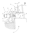
- Fig. 1 shows a perspective view of a first end clamp system 10 in a clamped state.
- a PV module 12 is clamped on its outer frame 14 on a support section 16.
- the support profile 16 may be an (extruded) rail which extends substantially in the longitudinal direction X.
- a transverse direction is designated Y.
- the vertical is labeled Z.
- the system 10 has a, preferably L-shaped, clamping bracket 18, a base member 20 and a clamping bolt 22, which is preferably realized as a threaded bolt and engages in the base member 20.
- the clamping angle 18 has a holding leg 24 for resting on the PV module 12 and a clamping leg 26 for coupling the clamping bracket 18 to the base member 20.
- the holding leg 24 is in the clamped state on an upper side 28 of the PV module 12 and the frame 14 on a flat surface.
- the connection of the retaining leg 24 with the base member 20, which engages positively in the support section 16, as will be explained in more detail below, via a toothing 30 which at a free end of the clamping leg 26 on a PV module 12 side facing is arranged.
- the toothing 30 of the clamping leg 26 interacts with a preferably step-shaped recess 32 on a module-facing side 68 (FIG. Fig. 2C ) of the base member 20.
- the recess 32 is here shaped so that it interacts positively with the toothing 30.
- the recess 32 here has a multiplicity of steps 34 arranged vertically one above the other.
- the clamping bolt 22 In order to press the clamping angle 18 vertically downward in the negative Z direction onto the PV module 12, the clamping bolt 22 is tightened.
- the clamping bolt 22 engages with its (threaded) shaft 38 in a (threaded) opening 36 in the base member 20.
- the head 40 of the clamping bolt 22 has a receptacle 42, such as a hex key receptacle, to the threaded shaft 38 further into the Turn in opening 36.
- the head 40 is freely accessible.
- a sleeve 44th be provided, which can press a washer 46 on an upper side of the retaining leg 24.
- the top of the retaining leg 24 has a in the Fig. 1 not shown opening 48, for example in the form of a slot 49 (FIG. Fig.
- the clamping bolt 22 engages through the opening 48 in the base member 20.
- the clamping bolt (head) outgoing clamping force can be evenly distributed to the support leg 24.
- the sleeve 44 can also be used to receive a spring device, not shown here, which will be described below with reference to the Fig. 2 will be described in more detail.
- the base element 20 is preferably flush with its module-facing side 70 on the frame 14 of the PV module 12.
- the clamping bracket 18 can be moved relative to the base member 20 both in the longitudinal direction X and in the vertical Z, in particular to perform height adjustments. Nevertheless, the clamping angle 18 and the base member 20 form a captive unit, ie, the components form a permanent bond, which is made possible by the support of the clamping bolt 22 in the opening 36.
- the clamping angle 18 with its toothing 30 on the clamping leg 26 can be brought into a desired height relative to the base element 20, so that the holding leg 24 rests on the upper side 28.
- the toothing 30, which is implemented here in the form of exemplarily three toothed racks extending in the Y-direction, engages in correspondingly formed steps 34. If the PV module 12 of the Fig. 1 flatter, so would the gearing 30 in the Fig. 1 engage in deeper levels 34 of the recess 32 in the base member 20.
- the clamping bracket 18 is pre-assembled, ie the module height is approximately preset, the clamping bolt 22 can be tightened to securely fix the PV module 12 on the support section 16. This will be described in more detail below.
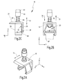
- FIGS. 2A-2C show the end clamp system 10 of Fig. 1 in a pre-assembly state. This means that the system 10 is not yet braced on the support section 16 for the purpose of fixing a PV module 12.
- Fig. 2A shows a perspective view of the system 10th
- Fig. 2B shows a front view of the system 10 when looking in the longitudinal direction X on the system 10.
- Fig. 2C shows a side view when looking along the Y direction on the system 10.
- the system 10 will be described with reference to FIGS Figures 2A-2C to be discribed.
- the Klemmwinkei 18 may be pre-assembled in a lowest position.
- the lowest position of the holding leg 24 is preferably on the base member 20.
- the toothing 30 of the clamping leg 26 engages in the lowest three stages 34 of the recess 32 in the base member 20 a. It is understood that the length of the retaining leg 24 in the X direction and the height of the clamping leg 26 in the Z direction can be varied. The height of the clamping leg 26 can also be selected so that the holding leg 24 does not rest in the free state on the base member 20, but has a distance from the top of the base member 20.
- the already mentioned above spring device is in the Fig. 2 shown in the form of a coil spring 50 which is slid over the shaft 38 of the clamping bolt 22 and is supported either on the head 40 of the clamping bolt 22 or on a cover of the sleeve 44.
- An opposite end of the coil spring 50 is supported on the washer 46, if any. If the washer 46 is not present, the coil spring 50 is supported directly on the top of the retaining leg 24.
- the diameter of the coil spring 50 is selected so that the coil spring does not fit through the opening 48 in the retaining leg 24.
- the sleeve 44 is dimensioned so that it can be plugged onto the shaft 38 of the clamping bolt 22 and bears against the head 40 of the clamping bolt 22.
- the sleeve 44 serves to accommodate the (compressed) coil spring 50 in the clamped state of the system 10, as shown by way of example in the Fig. 1 is shown.
- the sleeve 44 further serves a more uniform application of force from the head 40 in the holding leg 24 during a Verspannvorgangs, since the sleeve 44 is usually a larger diameter than the head 40 and thus the ratio of force above the slot and on the holding leg is better.
- the base member 20 has in the side view of Fig. 2C a substantially rectangular cross section.
- the base member 20 may have a trapezoidal cross section.
- a rectangular cross section would also be conceivable.
- the recess 32 with the steps 34 is in the module facing away side 68 (see. Fig. 2C ) of the base member 20 is provided.
- the module facing away from side 68 is opposite to a module-facing side 70 of the base member 20.
- the sides 68 and 70 are oriented parallel to one another and, in the clamped state, are preferably perpendicular to the top side of the supporting profile 16 or parallel to the edge of the PV module 12.
- the module-facing side 70 preferably closes flat against the edge of the PV module 12 in the clamped state at.
- a threaded post 52 may be provided in the interior of the base element 20, which is fixed by arms explained in more detail below.
- Fig. 2B is one compared to Fig. 1 modified support section 16 'shown with a closed top.
- the base element 20 is preferably laterally, ie substantially parallel to the Y direction, plugged by rotation about a peripheral edge of the support section 16 on the support section 16 and 16 '.
- the base member 20 is flexible and has in a region which comes into contact with the support section 16, for example, a tongue and groove connection, as exemplified in the Fig. 2B is indicated. It is understood that due to the possibility that the base member 20 is laterally attached to the support section 16, a certain play in the Z direction in the region of the tongue and groove connection is required. This game fundamentally justifies the risk that the base element is tilted when the system 10 is braced ( Fig.
- the Fig. 3A shows a perspective view.
- the Fig. 3B shows a plan view.
- Fig. 3C shows a side view along the Y-direction.
- the retaining leg 24 and the clamping leg 26 preferably include a right angle with each other (see. Fig. 3C ).
- the length of the legs 24 and 26 can be varied as desired.
- the toothing 30 On a module-facing side 82 of the clamping leg 26, the toothing 30 is provided.
- the toothing 30 has one or more toothed racks, which in the e.g. have a triangular cross section.
- the toothed strips extend over an entire width (parallel to the Y-direction) of the clamping leg 26 in order to securely engage in the steps 34 of the base element 20, regardless of a height to be set.
- the horizontal distance between two adjacent steps 34 is height dependent.
- the opening 48 which is preferably formed as a slot 49, is located in the holding leg 24.
- the holding leg 24 is tapered at its free end. This feature is optional.
- the slot 49 is preferably arranged centrally in the width of the clamping bracket 18.
- the slot 49 extends parallel to the longitudinal direction X of the support profile 16.
- the slot 49 should extend perpendicular to the longitudinal extent of the side wall of the PV module 12 in order to move the clamping bracket 18 when setting a desired module height of the PV module 12 so that the Gearing 30 is disengaged from the stepped recess 32 comes.
- the orientation of the slot 49 is in Fig. 3C indicated in the form of an extension 83 which extends parallel to the X direction.
- FIGS. 1 and 2 show different views of the in the FIGS. 1 and 2
- the base member 20 will be described in more detail below with common reference to all views of Figures 4A-4D to be discribed.
- Fig. 4A shows a perspective view.
- Fig. 4B shows a front view.
- Fig. 4C shows a plan view and
- Fig. 4D shows a side view.
- FIG. 4B In the front view of the Fig. 4B the optional trapezoidal shape (cross section) of the base member 20 is clearly visible.
- the Indian Fig. 2B Threaded collar 52 already shown can be placed in a groove 54 which is defined by two lateral support arms 56, which leave a gap between them to pass the clamping bolt 22.
- the support arms 56 project horizontally out of the obliquely arranged trapezoid legs 58-1 and 58-2.
- feet 60-1 and 60-2 are provided on the inside for supporting the trapezoidal legs 58 at the top of the support section 16.
- barb-shaped portions 62 may be provided at the free ends of the trapezoidal leg 58.
- the barb-shaped configuration of sections 62 is merely optional.
- the trapezoidal legs 58 are connected to each other via a horizontally oriented connecting leg 64.
- the opening 36 In an upper side 64 'of the connecting leg 64, the opening 36 (see. Fig. 1 ) intended.
- the opening 36 is formed here without thread, since in the illustrated embodiment of the base member 20, a threaded rod 52 is used, which has the thread for the clamping bolt 22.
- the step-shaped recess 32 is in the side view of Fig. 4D clearly visible.
- the top view of Fig. 4C shows that each of the trapezoidal legs 58-1 and 58-2 has an equal number of equidistant steps 34 which are paired opposite each other at the same height to engage the toothing 30 of the clamping leg 26.
- the variable relative distance between the steps 34 at the same height (in the Z direction) can be clearly seen.
- the steps 34 are formed by way of example in the form of a sawtooth profile.
- the teeth have an angle of eg 45 ° (cf. Fig. 4D ).
- the horizontal surface of a step 34 serves to initiate the vertical component of force during clamping of the system 10.
- the inclined surface of the step 34 simplifies the insertion of the teeth 30 in the stepped recess 32. It is understood that the angle of the steps 34 can be variably selected . In order to prevent too easy slipping of the toothing 30 out of the stepped recess 32 in the unstressed state of the system 10, the in the Fig. 4D horizontally represented part of the step 34 are also slightly inclined, so that the angle of 45 ° is slightly sharper, for example, includes only 40 °. The (lower) part of the step 34 would then be inclined with respect to the horizontal, for example, at 5 °.
- FIGS. 5A-5C show a second embodiment of the system 10 of Fig. 1 , Fig. 5A shows a perspective view. Fig. 5B shows a front view and Fig. 5C shows a side view of the system 10th
- the clamping leg 26 In the system 10 of the Fig. 5 the clamping leg 26 'on each of its sides 80 and 82, a toothing 30 on.
- the stepped recess 32 is formed to orient along an imaginary line 96 that defines an acute angle with the module-facing side 68 of the base member 20.
- the steps 34 of the recess 32 are rectangular, so that a first portion of each step is horizontal and a second section is vertically oriented. Of course, they may also slightly inclined relative to the horizontal and vertical sections, for example, 5-10%, wherein the clamping leg 26 is adjusted accordingly.
- the steps 34 are matched to the geometry of the free end of the clamping leg 26.
- the clamping leg 26 has an underside 90 which fits in a form-fitting manner in the steps 34. The underside 90 sits in the clamped state positively in one of the stages 34th
- the system 10 of Fig. 5 shows further modifications to the Fig. 2 on.
- the washer 46 is disposed between the head 40 and the coil spring 50 here.
- the coil spring 50 is supported at its opposite end on the holding leg 24.
- the sleeve 44 ' is firmly formed on the holding leg 24 and no longer designed as a loose movable sleeve 44, as exemplified in the Figures 2A-2C was shown.
- the sleeves 44 and 44 'as well as the spring means may be eliminated without limiting the functionality of the system 10.
- the sleeve 44 and 44 'in combination with the coil spring 50 is only for ease of assembly on site.
- the coil spring 50 causes the clamping bracket 18 is biased during a height adjustment in the direction of the stepped recess 32, so that the fitter can easily release the retaining leg 24 after a successful adjustment of height, then to clamp the system 10 with free hands.
- the system 10 is pre-assembled. This means that the system 10 first in a state according to Figures 2 and 5 located.
- the clamping bracket 18 is captively connected via the clamping bolt 22 to the base member 20.
- the clamping angle 18 is preferably arranged in the lowest position.
- the clamping bracket 18 is held biased by the spring 50 there.
- the right trapezoidal leg 58-2 is pressed downwards under a deformation of the base element 20, so that the section 62 of the right trapezoidal leg 58-2 inverts around the projecting free edge of the supporting profile 16.
- the flexibility required for this is inherent to the base element 20.
- the connecting leg 64 is designed so flexible that the trapezoidal leg 58-2 can be moved beyond the edge of the support section 16. Then snaps the section 62 back and you get the in the Fig. 2B exemplified situation.
- the relative height can now be determined as a function of the height of the side surface 71 (cf. Fig. 1 ) of the frame 14.
- the clamping bolt 22 is not braced in this state and allows a movement of the clamping bracket 18 against the spring 50.
- the clamping angle 18 can be moved either first horizontally and then subsequently vertically, or the clamping bracket 18 can be directly pulled obliquely out of the steps 34.
- the system 10 is then attached to the side surface 71 (FIG. Fig. 1 ) is pushed in the longitudinal direction X of the support section 16.
- the displacement is possible because between the jaw-shaped portions 62 of the trapezoidal leg 58 and the superior edge of the support section 16 a certain play in the height direction Z is present.
- the base element 20 can, of course, be attached directly to the desired position on the frame 14 of the PV module 12.
- the system 10 is braced by the clamping bolt 22 is moved in the direction of the base member 20.
- pressure is exerted on the retaining leg 24 and the clamping leg 26.
- the pressure on the retaining leg 24 causes the PV module 12 is clamped to the support profile 16.
- the pressure on the clamping leg 26 causes the base member is not tilted due to the toothing 30 and the bottom 90 relative to the horizontal, which is defined by the top of the support section 16.
- the individual components 18-22 of the system 10 can also be connected to one another at the construction site.
- the base member 20, the clamping bolt 22 and the clamping bracket 18 are then not pre-assembled.
- the assembly of these three components is time consuming and should therefore not be done on site.
- a first step S10 the base member 20 is laterally attached to the support section 16.
- a step S12 the clamping angle is moved relative to the base member 20 for height adjustment.
- the clamping angle is braced via the clamping bolt with the base element.
Abstract
Description
Die vorliegende Erfindung betrifft ein Endklemmen-System zur randseitigen Befestigung von Photovoltaikmodulen ("PV-Modulen") auf Tragprofilen, wobei das System einen Klemmwinkel, einen Spannbolzen und ein Basiselement aufweist.The present invention relates to an end clamp system for the edge mounting of photovoltaic modules ("PV modules") on support profiles, wherein the system has a clamping angle, a clamping bolt and a base member.
Ein System mit der gleichen Funktion wird in dem europäischen Patent
Das Dokument
Die
Die Montage des eben beschriebenen Endklemmen-Systems ist zeitaufwändig. Die Elemente können nur aufwändig vormontiert werden, so dass die Gefahr besteht, dass sich die zusammengesetzte Einheit auflöst, bevor sie auf einer Baustelle tatsächlich verbaut wird, weil insbesondere die Muffe abrutschen könnte. Die zusammengesetzte Einheit lässt sich schlecht in Längsrichtung der Tragschiene verschieben. Es werden viele Bauteile benötigt, um eine stabile Endklemme zu ermöglichen. Sobald die Muffe über den Klemmteilträger gestülpt ist, ist der Gewindebolzen und zumindest der untere Schenkel der Z-förmigen Klemmteils nicht mehr frei zugänglich. Aufgrund des sich einstellenden Winkels zwischen dem Modulrahmen und dem Endklemmen-System im verspannten Zustand, baut diese Einheit nicht kompakt.The assembly of the end clamp system just described is time consuming. The elements can only be preassembled consuming, so that there is a risk that the composite unit dissolves before it is actually installed on a construction site, especially because the sleeve could slip off. The composite unit is difficult to move in the longitudinal direction of the mounting rail. Many components are needed to provide a stable end clamp. Once the sleeve is slipped over the clamping part carrier, the threaded bolt and at least the lower leg of the Z-shaped clamping part is no longer freely accessible. Due to the adjusting angle between the module frame and the end clamp system in the clamped state, this unit does not build compact.
Es ist daher eine Aufgabe der vorliegenden Erfindung ein verbessertes Endklemmen-System sowie ein vereinfachtes Montageverfahren bereitzustellen.It is therefore an object of the present invention to provide an improved end clamp system and a simplified assembly method.
Diese Aufgabe wird durch ein Endklemmen-System für PV-Module mit einem Klemmwinkel, einem Spannbolzen und einem Basiselement gelöst, wobei das Basiselement längsverschieblich und formschlüssig in ein Tragprofil eingreift, auf dem die PV-Modul verspannt befestigt werden, wobei der Klemmwinkel einen Halteschenkel und einen Spannschenkel aufweist, wobei der Halteschenkel eine Öffnung hat, durch die der Spannbolzen bis ins Basiselement geführt ist, wobei das Basiselement auf einer modulabgewandten Seite eine Ausnehmung mit mehreren Stufen aufweist, wobei die Stufen ausgebildet sind, ein freies Ende des Spannschenkels oder eine korrespondierende Verzahnung auf einer modulzugewandten Seite des Spannschenkels höhenverstellbar abzustützen, wobei der Spannbolzen ein Gewindebolzen ist, der durch die Öffnung im Halteschenkel geführt ist, um in eine Gewindeöffnung im Basiselement oder in mindestens einen, im Basiselement gelagerten Gewindestein zwecks Verspannung einzugreifen..This object is achieved by an end clamp system for PV modules with a clamping bracket, a clamping bolt and a base element, wherein the base member engages longitudinally displaceable and form-fitting in a support profile on which the PV module are clamped attached, the clamping angle a holding leg and a clamping leg, wherein the holding leg has an opening through which the clamping bolt is guided to the base member, wherein the base member on a module side facing a recess having a plurality of steps, wherein the steps are formed, a free end of the clamping leg or a corresponding toothing height-adjustable support on a module-facing side of the clamping leg, wherein the clamping bolt is a threaded bolt which is guided through the opening in the holding leg to engage in a threaded opening in the base member or in at least one threaded rod mounted in the base element for the purpose of bracing.
Das System der Erfindung weist wenige Komponenten auf und ist vormontierbar. Die Komponenten des Systems halten zusammen. Die Gefahr, dass eine der Komponenten verloren geht, besteht nicht.The system of the invention has few components and is pre-assembled. The components of the system stick together. There is no danger that one of the components will be lost.
Das System ist auf der Baustelle einfach handhabbar. Die Höhe des Systems lässt sich ohne Probleme an eine Höhe des PV-Moduls anpassen, indem der Klemmwinkel, vorzugsweise gegen eine Federkraft, in seiner vormontierten Stellung aus der stufenförmigen Ausnehmung des Basiselements gelöst und auf eine gewünschte Höhe (Höhe des Modulrahmens) verbracht wird. Die stufenförmige Ausnehmung ist verantwortlich dafür, dass das Basiselement beim Verspannen des Systems nicht gegenüber dem Rand des PV-Moduls schräg verkippt. Die Spannkraft wird flächig über den Halteschenkel in das PV-Modul eingeleitet. Das System baut mit wenigen Komponenten sehr kurz.The system is easy to handle on the construction site. The height of the system can be easily adapted to a height of the PV module by the clamping angle, preferably released against a spring force in its pre-assembled position from the stepped recess of the base element and to a desired height (height of the module frame) is spent. The stepped recess is responsible for ensuring that the base element does not tilt obliquely with respect to the edge of the PV module when clamping the system. The clamping force is introduced flat over the holding leg into the PV module. The system is very short with few components.
Das System kann seitlich auf das Tragprofil aufgesteckt werden. Ein Verschieben des Systems im Tragprofil in der Längsrichtung des Tragprofils ist nicht erforderlich, allenfalls zum Zwecke einer Feinjustierung.The system can be attached to the side of the support profile. A displacement of the system in the support section in the longitudinal direction of the support profile is not required, if necessary for the purpose of fine adjustment.
Die Elemente des Systems können verliersicher vormontiert werden, so dass ein Monteur auf der Baustelle die Komponenten nicht erst zusammensetzen muss, um das System zu montieren.The elements of the system can be preassembled captive, so that a fitter on site not need to assemble the components first to assemble the system.
Vorzugsweise erfolgt die Abstützung ausschließlich parallel zu einer Wirkrichtung einer Verspannung. Auf diese Weise ist gewährleistet, dass die gesamte Spannkraft aufgewendet wird, um das PV-Modul sicher mit dem Tragprofil zu verklemmen. Schräg wirkende Kraftkomponenten, die zu einem Verkannten des Systems führen können, sind nicht vorhanden.Preferably, the support is exclusively parallel to a direction of action of a tension. This ensures that all the clamping force is used to securely clamp the PV module to the support profile. Oblique force components, which can lead to a misjudgment of the system, are not available.
Weiter ist es bevorzugt, wenn im verspannten Zustand des Systems der Halteschenkel im Wesentlichen parallel zu einer Oberseite der PV-Module ist und der Spannschenkel im Wesentlichen parallel zu einer Seitenfläche der PV-Module orientiert ist.Further, it is preferable if in the braced state of the system, the holding leg is substantially parallel to an upper side of the PV modules and the clamping leg is oriented substantially parallel to a side surface of the PV modules.
Der Halteschenkel sorgt so für eine sichere Verspannung der PV-Module auf dem Tragprofil. Das Basiselement dient zur seitlichen Fixierung des PV-Moduls, so dass dieses nach einer erfolgten Verspannung nicht mehr in einer horizontalen (seitlichen) Richtung beweglich ist.The retaining leg thus ensures a secure clamping of the PV modules on the support profile. The base element is used for lateral fixation of the PV module, so that this is no longer movable in a horizontal (lateral) direction after a successful bracing.
Weiter ist es bevorzugt, wenn der Halteschenkel und der Spannschenkel im Wesentlichen einen rechten Winkel einschließen, wobei das Basiselement eine Oberseite, eine modulabgewandte Seite und eine modulzugewandte Seite sowie eine Unterseite aufweist, wobei die modulabgewandte Seite und die modulzugewandte Seite sich gegenüberliegen, parallel zueinander orientiert sind und senkrecht zu dem Tragprofil orientiert sind, wenn das Basiselement in Eingriff mit dem Tragprofil ist.Furthermore, it is preferred if the holding leg and the clamping leg essentially enclose a right angle, the base element having an upper side, a module-facing side and a module-facing side and a lower side, wherein the module-facing side and the module-facing side face each other, oriented parallel to one another are oriented and perpendicular to the support profile when the base member is in engagement with the support profile.
In diesem Zustand kommt es zu keinen Kippmomenten, die eine schräge Krafteinleitung zur Folge haben können. Das System ist stabil, montagesicher und montagefreundlich.In this state, there are no overturning moments, which can result in an oblique introduction of force. The system is stable, secure and easy to install.
Ferner hat es sich als vorteilhaft herausgestellt, wenn die Öffnung im Halteschenkel ein Langloch mit einer Erstreckung ist, die im verspannten Zustand des Systems senkrecht zur Seitenfläche des PV-Moduls orientiert ist.Furthermore, it has been found to be advantageous if the opening in the holding leg is a slot having an extension which is oriented in the clamped state of the system perpendicular to the side surface of the PV module.
Das Langloch ermöglicht die (horizontale gerichtete) Bewegungskomponente, um den Spannschenkel oder dessen Verzahnung außer Eingriff mit der stufenförmigen Ausnehmung des Basiselements zu bringen, um den Klemmwinkel an die Höhe des PV-Moduls anzupassen.The slot allows the (horizontally directed) component of motion to disengage the clamping leg or its teeth from the stepped recess of the base member to adjust the clamping angle to the height of the PV module.
Gemäß einer weiteren bevorzugten Ausführungsform weist der Spannbolzen einen Schaft und einen Kopf auf, wobei der Kopf größer als die Öffnung im Halteschenkel ist und an einem Ende des Schafts vorgesehen ist.According to a further preferred embodiment, the clamping bolt has a shaft and a head, wherein the head is larger than the opening in the holding leg and is provided at one end of the shaft.
Durch diese Maßnahme hält der Kopf den Klemmwinkel vormontiert am Basiselement fest.By this measure, the head holds the clamping bracket pre-mounted on the base element.
Außerdem hat es sich als vorteilhaft herausgestellt, wenn ferner eine Spiralfeder und/oder eine Unterlegscheibe vorgesehen sind, die auf den Spannbolzen aufgesteckt sind.In addition, it has been found to be advantageous if, in addition, a coil spring and / or a washer are provided, which are attached to the clamping bolt.
Die Federeinrichtung bewirkt eine Vorspannung des Klemmwinkels gegen das Basiselement. Dies ist für die Vormontage vorteilhaft. Der Klemmwinkel rutscht nicht entlang des Spannbolzens auf und ab, so dass ein Transport zur Baustelle geräuschlos erfolgen kann. Die Systeme können alle in einem gleichbleibenden Zustand ausgeliefert werden, bis sie auf einer Baustelle zum Einsatz kommen. Die Feder unterstützt ferner den Montagevorgang, weil sie den Klemmwinkel, sobald dieser in seiner richtigen Höhe eingestellt ist, in der eingestellten Höhe hält.The spring means causes a bias of the clamping angle against the base member. This is advantageous for pre-assembly. The clamping angle does not slip up and down along the clamping bolt, so that transport to the construction site can take place noiselessly. The systems can all be delivered in a consistent condition until they are used on a construction site. The spring also assists in the assembly process by holding the clamp angle at the set height as soon as it has been adjusted to its correct height.
Weiter ist es bevorzugt, wenn das Basiselement einen trapezförmigen Querschnitt mit zwei sich in einem Winkel gegenüberliegenden Trapezschenkel aufweist, die derart flexibel ausgebildet sind, dass das Basiselement seitlich auf das Tragprofil aufklemmbar ist.Further, it is preferred if the base element has a trapezoidal cross section with two opposite at an angle trapezoidal leg, which are designed so flexible that the base member is laterally clamped onto the support section.
Die oben genannte Aufgabe wird ferner durch ein Verfahren zum Befestigen eines PV-Moduls auf einem Tragprofil in einem äußeren Randbereich des PV-Moduls, den kein anderes PV-Modul gegenüberliegt, gelöst, und zwar unter Verwendung eines Endklemmen-Systems gemäß der Erfindung, wobei das Verfahren die folgenden Schritte umfasst: seitliches, formschlüssiges Aufstecken des Basiselements auf das Tragprofil an einem Ort einer gewünschten Fixierung; Bewegen des Klemmwinkels relativ zum Basiselement, so dass der Halteschenkel auf einer Oberseite des PV-Moduls aufwiegt und so dass der Spannschenkel in die stufenförmige Ausnehmung der modulabgewandten Seite des Basiselements eingreift; und Verspannen des Klemmwinkels mit dem Basiselement durch Bewegen des Klemmschenkels senkrecht zum Tragprofil, indem der Spannbolzen angezogen wird.The above object is further achieved by a method for mounting a PV module on a support profile in an outer peripheral area of the PV module, which is not opposed to any other PV module, using an end clamp system according to the invention the method comprises the following steps: lateral, positive attachment of the base element to the support profile at a location of a desired fixation; Moving the clamping angle relative to the base member, so that the retaining leg on a top of the PV module and outweighs so that the clamping leg engages in the stepped recess of the module side facing away from the base member; and tightening the clamping angle with the base member by moving the clamping leg perpendicular to the supporting profile by tightening the clamping bolt.
Weiter ist es bevorzugt, wenn das Verfahren ein Verschieben des Basiselements in Längsrichtung des Tragprofils aufweist, so dass das Basiselement mit einer modulzugewandten Seite an einer Seitenfläche des PV-Moduls anliegt.Further, it is preferred if the method comprises a displacement of the base member in the longitudinal direction of the support profile, so that the base member rests with a side facing the module on a side surface of the PV module.
Außerdem ist es von Vorteil, wenn der Spannbolzen durch den Halteschenkel durchgeführt und der durchgeführte Spannbolzen mit dem Basiselement verbunden wird.Moreover, it is advantageous if the clamping bolt is performed by the holding leg and the performed clamping bolt is connected to the base member.
Es versteht sich, dass die vorstehend genannten und die nachstehend noch zu erläuternden Merkmale nicht nur in der jeweils angegebenen Kombination, sondern auch in anderen Kombinationen oder in Alleinstellung verwendbar sind, ohne den Rahmen der vorliegenden Erfindung zu verlassen.It is understood that the features mentioned above and those yet to be explained below can be used not only in the particular combination given, but also in other combinations or in isolation, without departing from the scope of the present invention.
Ausführungsbeispiele der Erfindung sind in der Zeichnung dargestellt und werden in der nachfolgenden Beschreibung näher erläutert. Es zeigen:
- Fig. 1
- eine perspektivische Ansicht eines Endklemmen-Systems gemäß der Erfindung in einem verspannten Zustand;
- Fig. 2A-C
- verschiedene Ansichten des Endklemmen-Systems der
Fig. 1 in isolierter Darstellung; - Fig. 3A-C
- verschiedene Ansichten eines Klemmwinkels, wie er in den
Figuren 1 und2 gezeigt ist; - Fig. 4A-D
- verschiedene Ansichten eines Basiselements, wie es in den
Figuren 1 und2 gezeigt ist; - Fig. 5A-C
- verschiedene Ansichten eines abgewandelten Endklemmen-Systems; und
- Fig.6
- ein Flussdiagramm eines Montageverfahrens gemäß der Erfindung.
- Fig. 1
- a perspective view of an end clamp system according to the invention in a clamped state;
- Fig. 2A-C
- different views of the terminal system of
Fig. 1 in isolated form; - Fig. 3A-C
- different views of a clamping angle, as in the
FIGS. 1 and2 is shown; - Fig. 4A-D
- different views of a base element, as in the
FIGS. 1 and2 is shown; - Fig. 5A-C
- different views of a modified end clamp system; and
- Figure 6
- a flow chart of an assembly method according to the invention.
In der nachfolgenden Beschreibung werden gleiche Elemente mit den gleichen Bezugszeichen versehen. Das erfindungsgemäße Endklemmen-System wird generell mit dem Bezugszeichen 10 bezeichnet.In the following description, like elements will be given the same reference numerals. The end clamp system according to the invention is generally designated by the
Das System 10 weist einen, vorzugsweise L-förmigen, Klemmwinkel 18, ein Basiselement 20 sowie einen Spannbolzen 22 auf, der vorzugsweise als Gewindebolzen realisiert ist und in das Basiselement 20 eingreift. Der Klemmwinkel 18 weist einen Halteschenkel 24 zur Auflage auf dem PV-Modul 12 sowie einen Spannschenkel 26 zur Kopplung des Klemmwinkels 18 an das Basiselement 20 auf. Der Halteschenkel 24 liegt im verspannten Zustand auf einer Oberseite 28 des PV-Moduls 12 bzw. des Rahmens 14 flächig auf. Die Verbindung des Halteschenkel 24 mit dem Basiselement 20, welches formschlüssig in das Tragprofil 16 eingreift, wie es nachfolgend noch näher erläutert werden wird, erfolgt über eine Verzahnung 30, die an einem freien Ende des Spannschenkels 26 auf einer dem PV-Modul 12 zugewandten Seite angeordnet ist. Die Verzahnung 30 des Spannschenkels 26 wechselwirkt mit einer, vorzugsweise stufenförmigen, Ausnehmung 32 auf einer modulabgewandten Seite 68 (
Um den Klemmwinkel 18 in der negativen Z-Richtung vertikal nach unten auf das PV-Modul 12 zu drücken, wird der Spannbolzen 22 angezogen. Der Spannbolzen 22 greift mit seinem (Gewinde-)Schaft 38 in eine (Gewinde-)Öffnung 36 im Basiselement 20. Der Kopf 40 des Spannbolzens 22 weist eine Aufnahme 42, z.B. eine Sechskantschlüssel-Aufnahme, auf, um den Gewindeschaft 38 weiter in die Öffnung 36 einzudrehen. Der Kopf 40 ist frei zugänglich. Unterhalb des Kopfs 40 kann eine Hülse 44 vorgesehen sein, die eine Unterlegscheibe 46 auf eine Oberseite des Halteschenkels 24 drücken kann. Die Oberseite des Halteschenkels 24 weist eine in der
Im verspannten Zustand des Systems 10 liegt das Basiselement 20 mit seiner modulzugewandten Seite 70 vorzugsweise bündig an dem Rahmen 14 des PV-Moduls 12 an. Solange der Spannbolzen 22 nicht verspannt wird, kann der Klemmwinkel 18 sowohl in der Längsrichtung X als auch in der Vertikalen Z relativ zum Basiselement 20 bewegt werden, insbesondere um Höhenverstellungen durchzuführen. Trotzdem bilden der Klemmwinkel 18 und das Basiselement 20 eine verliersichere Einheit, d.h. die Komponenten bilden einen unlösbaren Verbund, der durch den Halt des Spannbolzens 22 in der Öffnung 36 ermöglicht wird. Je nach Höhe des verwendeten PV-Moduls 12 kann der Klemmwinkel 18 mit seiner Verzahnung 30 am Spannschenkel 26 in eine gewünschte Höhe relativ zum Basiselement 20 gebracht werden, so dass der Halteschenkel 24 auf der Oberseite 28 aufliegt. Die Verzahnung 30, die hier in Form von exemplarisch drei sich in der Y-Richtung erstreckenden Zahnleisten implementiert ist, greift in entsprechend ausgebildete Stufen 34 ein. Wäre das PV-Modul 12 der
Die
Im freien Zustand des Systems 10 kann der Klemmwinkei 18 in einer tiefsten Stellung vormontiert sein. In der tiefsten Stellung liegt der Halteschenkel 24 vorzugsweise auf dem Basiselement 20 auf. Die Verzahnung 30 des Spannschenkels 26 greift in die untersten drei Stufen 34 der Ausnehmung 32 im Basiselement 20 ein. Es versteht, dass die Länge des Halteschenkels 24 in der X-Richtung sowie die Höhe des Spannschenkels 26 in der Z-Richtung variiert werden kann. Die Höhe des Spannschenkels 26 kann auch so gewählt sein, dass der Halteschenkel 24 im freien Zustand nicht auf dem Basiselement 20 ruht, sondern einen Abstand zur Oberseite des Basiselements 20 aufweist. Dies bedeutet mit anderen Worten, dass über die Höhe des Spannschenkels 26 eine weitere Möglichkeit besteht, unterschiedlich hohe PV-Module 12 fixieren zu können (Baukastensystem). Eine effektive Höhe (Projektion auf die Z-Achse) der Ausnehmung 32 im Basiselement 20 definiert eine Höhenverstellbarkeit eines spezifischen Klemmwinkels 18.In the free state of the
Die oben bereits erwähnte Federeinrichtung ist in der
Das Basiselement 20 weist in der Seitenansicht der
Wenn die Öffnung 36 im Basiselement 20 nicht selbst mit einem Innengewinde.zur Aufnahme des Gewindeschafts 38 versehen ist, kann z.B. ein Gewindestein 52 im Inneren des Basiselements 20 vorgesehen sein, der durch nachfolgend noch näher erläuterte Arme fixiert ist.If the
In
Unter gemeinsamer Bezugnahme auf die
Der Halteschenkel 24 und der Spannschenkel 26 schließen vorzugsweise einen rechten Winkel miteinander ein (vgl.
An einer modulzugewandten Seite 82 des Spannschenkels 26 ist die Verzahnung 30 vorgesehen. Die Verzahnung 30 weist eine oder mehrere Zahnleisten auf, die im z.B. einen dreieckigen Querschnitt haben. Die Zahnleisten erstrecken sich über eine gesamte Breite (parallel zur Y-Richtung) des Spannschenkels 26, um unabhängig von einer einzustellende Höhe sicher in die Stufen 34 des Basiselements 20 einzugreifen. Der horizontale Abstand zwischen zwei benachbarten Stufen 34 ist höhenabhängig. Je höher die Verzahnung 30 in Eingriff mit den Stufen 34 im Basiselement 20 kommt, desto geringer sind die Relativabstände benachbarter Stufen 34 gleicher Höhe. Um aber auch sicher in die unterste Stufe 34 in der stufenförmigen Ausnehmung 32 des Basiselements 20 einzugreifen, empfiehlt es sich, die Zahnleisten über die gesamte Breite des Spannschenkels 26 vorzusehen.On a module-facing
Auf einer modulabgewandten Seite 80 des Spannschenkels 26 ist keine Verzahnung 30 vorgesehen.On a module side facing away from 80 of the clamping
Die Öffnung 48, die vorzugsweise als Langloch 49 ausgebildet ist, befindet sich im Halteschenkel 24. Der Halteschenkel 24 ist an seinem freien Ende zugespitzt ausgebildet. Dieses Merkmal ist optional.The
Das Langloch 49 ist vorzugsweise mittig in der Breite des Klemmwinkels 18 angeordnet. Das Langloch 49 erstreckt sich parallel zur Längsrichtung X des Tragprofils 16. Das Langloch 49 sollte sich senkrecht zur Längserstreckung der Seitenwand des PV-Moduls 12 erstrecken, um den Klemmwinkel 18 beim Einstellen einer gewünschten Modulhöhe vom PV-Modul 12 wegbewegen zu können, damit die Verzahnung 30 außer Eingriff mit der stufenförmigen Ausnehmung 32 kommt. Die Ausrichtung des Langlochs 49 ist in
Die
In der Vorderansicht der
Die Trapezschenkel 58 sind über einen horizontal orientierten Verbindungsschenkel 64 miteinander verbunden. In einer Oberseite 64' des Verbindungsschenkels 64 ist die Öffnung 36 (vgl.
Die stufenförmige Ausnehmung 32 ist in der Seitenansicht der
Die
Beim System 10 der
Das System 10 der
Es versteht sich, dass die Hülsen 44 und 44' sowie die Federeinrichtung weggelassen werden können, ohne die Funktionalität des Systems 10 einzuschränken. Die Hülse 44 und 44' in Kombination mit der Spiralfeder 50 dient lediglich dem Montagekomfort auf der Baustelle. Die Spiralfeder 50 bewirkt, dass der Klemmwinkel 18 während einer Höhenverstellung in Richtung der stufenförmigen Ausnehmung 32 vorgespannt ist, so dass der Monteur nach einer erfolgten Höhenanpassung den Halteschenkel 24 einfach wieder loslassen kann, um das System 10 anschließend mit freien Händen zu verspannen.It will be appreciated that the
Im Nachfolgenden wird beschrieben, wie das System 10 der Erfindung während einer Montage eingesetzt wird.The following describes how the
Üblicherweise ist das System 10 vormontiert. Dies bedeutet, dass sich das System 10 zuerst in einem Zustand gemäß den
Zu Beginn der Montage des Systems 10 gibt es dann zwei Möglichkeiten, wie gestartet werden kann. Entweder wird das System 10 in seiner Ausgangsstellung, wie sie in den
Je nachdem, ob man die Höhe des Klemmwinkels 18 relativ zum Basiselement bereits vorab eingestellt hatte oder nicht, kann nun die Relativhöhe in Abhängigkeit der Höhe der Seitenfläche 71 (vgl.
Wenn die Einstellung der Höhe erst erfolgt, nachdem das Basiselement 20 auf das Tragprofil 16 gesteckt wurde, wird das System 10 anschließend an die Seitenfläche 71 (
Wurde die Höhe bereits vorab eingestellt, kann das Basiselement 20 natürlich direkt an der vorgewünschten Position am Rahmen 14 des PV-Moduls 12 aufgesteckt werden.If the height has already been set in advance, the
Anschließend wird das System 10 verspannt, indem der Spannbolzen 22 in Richtung des Basiselements 20 bewegt wird. Dadurch wird Druck auf den Halteschenkel 24 und den Spannschenkel 26 ausgeübt. Der Druck auf den Halteschenkel 24 bewirkt, dass das PV-Modul 12 mit dem Tragprofil 16 verklemmt wird. Der Druck auf den Spannschenkel 26 bewirkt, dass das Basiselement wegen der Verzahnung 30 bzw. des Bodens 90 nicht gegenüber der Horizontalen verkippt, die durch die Oberseite des Tragprofils 16 definiert ist.Subsequently, the
Selbstverständlich können die einzelnen Komponenten 18 - 22 des Systems 10 auch erst auf der Baustelle miteinander verbunden werden. Das Basiselement 20, der Spannbolzen 22 und der Klemmwinkel 18 sind dann nicht vormontiert. Die Montage dieser drei Komponenten ist zeitaufwändig und sollte deshalb nicht auf der Baustelle erfolgen.Of course, the individual components 18-22 of the
Die Schritte der Montage auf der Baustelle sind schematisch im Flussdiagramm der
Gleiche Teile und Merkmale wurden mit gleichen Bezugszeichen versehen. Die in der Beschreibung enthaltenen Offenbarungen sind sinngemäß auf gleiche Teile und Merkmale mit denselben Bezugszeichen übertragbar. Lage- und Orientierungsangaben (z.B. "seitlich", "längs", "quer", "horizontal", "vertikal" und Ähnliches) sind auf die unmittelbar beschriebene Figur bezogen. Bei einer Änderung der Lage oder Orientierung sind diese Angaben aber sinngemäß auf die neue Lage bzw. Orientierung zu übertragen.Identical parts and features have been given the same reference numerals. The disclosures contained in the description are mutatis mutandis to like parts and features with the same reference numerals transferable. Location and orientation indications (e.g., "sideways," "longitudinal," "transverse," "horizontal," "vertical," and the like) are related to the instantly described figure. In the event of a change in position or orientation, however, these details must be transferred analogously to the new position or orientation.
Claims (11)
Applications Claiming Priority (1)
| Application Number | Priority Date | Filing Date | Title |
|---|---|---|---|
| DE102011118560A DE102011118560A1 (en) | 2011-11-10 | 2011-11-10 | End clamps for framed photovoltaic modules |
Publications (2)
| Publication Number | Publication Date |
|---|---|
| EP2592365A2 true EP2592365A2 (en) | 2013-05-15 |
| EP2592365A3 EP2592365A3 (en) | 2014-07-02 |
Family
ID=47143754
Family Applications (1)
| Application Number | Title | Priority Date | Filing Date |
|---|---|---|---|
| EP12192032.6A Withdrawn EP2592365A3 (en) | 2011-11-10 | 2012-11-09 | End clamps for framed photovoltaic modules |
Country Status (2)
| Country | Link |
|---|---|
| EP (1) | EP2592365A3 (en) |
| DE (1) | DE102011118560A1 (en) |
Cited By (18)
| Publication number | Priority date | Publication date | Assignee | Title |
|---|---|---|---|---|
| JP2015034388A (en) * | 2013-08-08 | 2015-02-19 | 元旦ビューティ工業株式会社 | Member and structure for attaching panel |
| US9673583B2 (en) | 2015-08-28 | 2017-06-06 | Solarcity Corporation | Photovoltaic mounting rail connector with drop-down connection to first photovoltaic module and slide-in connection to second photovoltaic module |
| JP2017223109A (en) * | 2017-08-10 | 2017-12-21 | 元旦ビューティ工業株式会社 | Panel installation member and installation structure |
| US9876462B2 (en) | 2015-08-27 | 2018-01-23 | Solarcity Corporation | Support system for photovoltaic mounting rail having cylindrical base that rotates into a locked position |
| US9874021B2 (en) | 2015-08-28 | 2018-01-23 | Solarcity Corporation | Tile and slate roof flashing systems |
| EP3364124A1 (en) * | 2017-02-08 | 2018-08-22 | Esdec B.V. | Device and method for fixing solar paneel on a support rail for solar panels |
| GB2529687B (en) * | 2014-08-29 | 2018-12-19 | Milenco Ltd | Improved gripper pad for towing mirror clamp |
| CN110101230A (en) * | 2019-04-22 | 2019-08-09 | 浙江大学 | A kind of adjustment height support leg |
| US10680417B2 (en) | 2015-07-23 | 2020-06-09 | Rittal Gmbh & Co. Kg | Securing system for securing a roof structure in a notch on the roof of a switch cabinet |
| WO2020187472A1 (en) * | 2019-09-05 | 2020-09-24 | Aerocompact Gmbh | End clamp for fastening a framed pv module |
| US11056998B2 (en) * | 2017-05-01 | 2021-07-06 | Hubbell Incorporated | Universal bonding end clamp |
| US11070166B2 (en) | 2018-04-19 | 2021-07-20 | Energy Consultants Group, LLC | Adjustable mounting device |
| US11261893B2 (en) * | 2017-08-15 | 2022-03-01 | National Nail Corp. | Hidden fastener unit and related method of use |
| USD945870S1 (en) | 2020-11-17 | 2022-03-15 | National Nail Corp. | Fastener positioning device |
| US11296648B1 (en) | 2021-05-14 | 2022-04-05 | Sunmodo Corporation | Solar panel racking system and devices for the same |
| US11603670B2 (en) | 2017-08-15 | 2023-03-14 | National Nail Corp. | Hidden fastener unit and related method of use |
| US11757398B2 (en) * | 2015-03-11 | 2023-09-12 | Unirac Inc. | Universal sloped roof solar panel mounting system |
| USD1022684S1 (en) | 2023-02-23 | 2024-04-16 | National Nail Corp. | Fastener positioning device |
Families Citing this family (2)
| Publication number | Priority date | Publication date | Assignee | Title |
|---|---|---|---|---|
| CN104022722B (en) * | 2014-05-19 | 2016-03-30 | 苏州爱康金属科技有限公司 | Standing-seam color steel roofing photovoltaic support structure |
| US10240820B2 (en) * | 2015-03-25 | 2019-03-26 | Ironridge, Inc. | Clamp for securing and electrically bonding solar panels to a rail support |
Citations (6)
| Publication number | Priority date | Publication date | Assignee | Title |
|---|---|---|---|---|
| DE202004015815U1 (en) | 2004-10-09 | 2004-12-30 | Veloflex Carsten Thormählen (GmbH & Co.) | Case for items with a rectangular format such as writing or sketch pads and the like comprises a flap and a bottom which are located at its short edges |
| DE202006013261U1 (en) | 2006-08-24 | 2006-11-30 | Sbu Photovoltaik Gmbh | Fixing for solar module external frame sections in end regions of carriers has spreader insert to attach frame to carrier |
| DE102006000089A1 (en) | 2006-02-23 | 2007-08-30 | Hilti Ag | Fastening device for fixing solar panels to a mounting rail |
| DE202009010487U1 (en) | 2009-08-03 | 2009-12-10 | Schletter Gmbh | End clamp for mounting framed PV modules |
| EP2132495B1 (en) | 2007-03-30 | 2010-12-29 | Haticon GmbH | Fixture device for solar modules |
| DE202011001761U1 (en) | 2011-01-20 | 2011-04-21 | Vm Edelstahltechnik Gmbh | clamping device |
Family Cites Families (6)
| Publication number | Priority date | Publication date | Assignee | Title |
|---|---|---|---|---|
| DE10145393C1 (en) * | 2001-09-14 | 2003-05-22 | Manet Glas Systeme Gmbh Thaur | Solar module fixing device has holder arms fitted to coupling profile provided with interchangable end pieces dependent on solar module type |
| DE202004015811U1 (en) * | 2004-10-13 | 2004-12-16 | Bbt Thermotechnik Gmbh | Fastening device for at least one solar panel |
| NL2001380C2 (en) * | 2008-03-17 | 2009-09-21 | Ubbink Bv | Sloping roof with solar panel holder. |
| FR2950375A1 (en) * | 2009-09-21 | 2011-03-25 | Atrya | Roof system for covering e.g. buildings, has assembling rails to assemble lateral edges of frames of solar modules or panels, and removable maintaining and/or blocking unit to removably maintain and/or block solar modules/panels on rails |
| DE202010000121U1 (en) * | 2010-02-04 | 2010-06-10 | Alcom International Gmbh | clamping profile |
| ES1071742Y (en) * | 2010-02-10 | 2010-06-25 | Producciones Mitjavila Sa | SOLAR PANEL FIXING STRUCTURE |
-
2011
- 2011-11-10 DE DE102011118560A patent/DE102011118560A1/en not_active Withdrawn
-
2012
- 2012-11-09 EP EP12192032.6A patent/EP2592365A3/en not_active Withdrawn
Patent Citations (6)
| Publication number | Priority date | Publication date | Assignee | Title |
|---|---|---|---|---|
| DE202004015815U1 (en) | 2004-10-09 | 2004-12-30 | Veloflex Carsten Thormählen (GmbH & Co.) | Case for items with a rectangular format such as writing or sketch pads and the like comprises a flap and a bottom which are located at its short edges |
| DE102006000089A1 (en) | 2006-02-23 | 2007-08-30 | Hilti Ag | Fastening device for fixing solar panels to a mounting rail |
| DE202006013261U1 (en) | 2006-08-24 | 2006-11-30 | Sbu Photovoltaik Gmbh | Fixing for solar module external frame sections in end regions of carriers has spreader insert to attach frame to carrier |
| EP2132495B1 (en) | 2007-03-30 | 2010-12-29 | Haticon GmbH | Fixture device for solar modules |
| DE202009010487U1 (en) | 2009-08-03 | 2009-12-10 | Schletter Gmbh | End clamp for mounting framed PV modules |
| DE202011001761U1 (en) | 2011-01-20 | 2011-04-21 | Vm Edelstahltechnik Gmbh | clamping device |
Cited By (25)
| Publication number | Priority date | Publication date | Assignee | Title |
|---|---|---|---|---|
| JP2015034388A (en) * | 2013-08-08 | 2015-02-19 | 元旦ビューティ工業株式会社 | Member and structure for attaching panel |
| GB2529687B (en) * | 2014-08-29 | 2018-12-19 | Milenco Ltd | Improved gripper pad for towing mirror clamp |
| US11757398B2 (en) * | 2015-03-11 | 2023-09-12 | Unirac Inc. | Universal sloped roof solar panel mounting system |
| US10680417B2 (en) | 2015-07-23 | 2020-06-09 | Rittal Gmbh & Co. Kg | Securing system for securing a roof structure in a notch on the roof of a switch cabinet |
| US9876462B2 (en) | 2015-08-27 | 2018-01-23 | Solarcity Corporation | Support system for photovoltaic mounting rail having cylindrical base that rotates into a locked position |
| US9874021B2 (en) | 2015-08-28 | 2018-01-23 | Solarcity Corporation | Tile and slate roof flashing systems |
| US9673583B2 (en) | 2015-08-28 | 2017-06-06 | Solarcity Corporation | Photovoltaic mounting rail connector with drop-down connection to first photovoltaic module and slide-in connection to second photovoltaic module |
| NL2018346B1 (en) * | 2017-02-08 | 2018-09-03 | Esdec B V | Device and method for fixing solar panels on a mounting rail for solar panels |
| EP3364124A1 (en) * | 2017-02-08 | 2018-08-22 | Esdec B.V. | Device and method for fixing solar paneel on a support rail for solar panels |
| US11056998B2 (en) * | 2017-05-01 | 2021-07-06 | Hubbell Incorporated | Universal bonding end clamp |
| JP2017223109A (en) * | 2017-08-10 | 2017-12-21 | 元旦ビューティ工業株式会社 | Panel installation member and installation structure |
| US11603670B2 (en) | 2017-08-15 | 2023-03-14 | National Nail Corp. | Hidden fastener unit and related method of use |
| US11920618B2 (en) | 2017-08-15 | 2024-03-05 | National Nail Corp. | Hidden fastener unit and related method of use |
| US11261893B2 (en) * | 2017-08-15 | 2022-03-01 | National Nail Corp. | Hidden fastener unit and related method of use |
| US11070166B2 (en) | 2018-04-19 | 2021-07-20 | Energy Consultants Group, LLC | Adjustable mounting device |
| CN110101230A (en) * | 2019-04-22 | 2019-08-09 | 浙江大学 | A kind of adjustment height support leg |
| CN110101230B (en) * | 2019-04-22 | 2021-01-08 | 浙江大学 | Height-adjustable supporting leg |
| WO2021043407A1 (en) * | 2019-09-05 | 2021-03-11 | Aerocompact Gmbh | End clamp for fastening a framed pv module |
| WO2020187472A1 (en) * | 2019-09-05 | 2020-09-24 | Aerocompact Gmbh | End clamp for fastening a framed pv module |
| USD945870S1 (en) | 2020-11-17 | 2022-03-15 | National Nail Corp. | Fastener positioning device |
| US11552591B2 (en) | 2021-05-14 | 2023-01-10 | Sunmodo Corporation | Solar panel racking system and devices for the same |
| US11296648B1 (en) | 2021-05-14 | 2022-04-05 | Sunmodo Corporation | Solar panel racking system and devices for the same |
| US11621665B2 (en) | 2021-05-14 | 2023-04-04 | Sunmode Corporation | Solar panel racking system and devices for the same |
| US11784607B2 (en) | 2021-05-14 | 2023-10-10 | Sunmodo Corporation | Solar panel racking system and devices for the same |
| USD1022684S1 (en) | 2023-02-23 | 2024-04-16 | National Nail Corp. | Fastener positioning device |
Also Published As
| Publication number | Publication date |
|---|---|
| DE102011118560A1 (en) | 2013-05-16 |
| EP2592365A3 (en) | 2014-07-02 |
Similar Documents
| Publication | Publication Date | Title |
|---|---|---|
| EP2592365A2 (en) | End clamps for framed photovoltaic modules | |
| DE202011107843U1 (en) | End clamps for framed photovoltaic modules | |
| EP1899552B1 (en) | Ceiling formwork system | |
| EP1647782A2 (en) | Supporting device for at least one solar collector | |
| AT412909B (en) | DEVICE FOR FIXING SOLAR MODULES TO FASTENING PROFILES | |
| EP0212228B1 (en) | Device for anchoring slabs | |
| WO2012116777A2 (en) | Fastening element for a solar module frame | |
| EP2093524A1 (en) | Device for mounting solar modules | |
| EP2498023A1 (en) | Standardised fixing system for photovoltaic modules and assembly method | |
| LU85715A1 (en) | POWERFUL-ELASTIC RAIL MOUNTING FOR RAILWAYS | |
| AT519224B1 (en) | Anchor unit for the person to be secured and method for forming the same | |
| AT10883U1 (en) | FASTENING DEVICE WITH A CLAMPING DEVICE | |
| EP2378221A2 (en) | Mounting system for solar modules and method for mounting a solar assembly | |
| DE202007012830U1 (en) | Vario carrier | |
| DE102012004773A1 (en) | Device for supporting photovoltaic modules on open spaces, has module carriers attached to photovoltaic module, and holding unit movable in longitudinal direction at one of module carriers at which module is attached to carrier | |
| DE10262175B4 (en) | Antenna holder with a mounting base having fastening elements for fastening the base to roof beams or slats | |
| CH704215A2 (en) | Sanitary tray support, in particular shower tray support. | |
| DE19907781A1 (en) | Molding box has flat hollow base, lengthwise and transverse walls, tension bars and nuts on threaded ends of tie rods. | |
| DE3038019C2 (en) | Grid ceiling | |
| EP3599335B1 (en) | Lowerable seal, in particular for sliding doors | |
| EP3401452A1 (en) | Fitting device for a bathroom item | |
| DE3003867A1 (en) | Railway rail force-locked resilient mounting - has loop abutment shank lugs elastically prestressed in row of anchor recesses | |
| DE102018203080B4 (en) | FOUNDATION SYSTEM FOR THE STORAGE OF SOLAR PANELS ARRANGED ALONGSIDE | |
| WO2015074933A1 (en) | Holding device for a housing and method for mounting the housing using the holding device | |
| EP3486400A1 (en) | Substructure of a façade lining and method for mounting a substructure |
Legal Events
| Date | Code | Title | Description |
|---|---|---|---|
| PUAI | Public reference made under article 153(3) epc to a published international application that has entered the european phase |
Free format text: ORIGINAL CODE: 0009012 |
|
| AK | Designated contracting states |
Kind code of ref document: A2 Designated state(s): AL AT BE BG CH CY CZ DE DK EE ES FI FR GB GR HR HU IE IS IT LI LT LU LV MC MK MT NL NO PL PT RO RS SE SI SK SM TR |
|
| AX | Request for extension of the european patent |
Extension state: BA ME |
|
| PUAL | Search report despatched |
Free format text: ORIGINAL CODE: 0009013 |
|
| AK | Designated contracting states |
Kind code of ref document: A3 Designated state(s): AL AT BE BG CH CY CZ DE DK EE ES FI FR GB GR HR HU IE IS IT LI LT LU LV MC MK MT NL NO PL PT RO RS SE SI SK SM TR |
|
| AX | Request for extension of the european patent |
Extension state: BA ME |
|
| RIC1 | Information provided on ipc code assigned before grant |
Ipc: F24J 2/52 20060101AFI20140528BHEP Ipc: H01L 31/042 20140101ALI20140528BHEP |
|
| 17P | Request for examination filed |
Effective date: 20141203 |
|
| RBV | Designated contracting states (corrected) |
Designated state(s): AL AT BE BG CH CY CZ DE DK EE ES FI FR GB GR HR HU IE IS IT LI LT LU LV MC MK MT NL NO PL PT RO RS SE SI SK SM TR |
|
| STAA | Information on the status of an ep patent application or granted ep patent |
Free format text: STATUS: THE APPLICATION IS DEEMED TO BE WITHDRAWN |
|
| 18D | Application deemed to be withdrawn |
Effective date: 20160601 |