US11552591B2 - Solar panel racking system and devices for the same - Google Patents
Solar panel racking system and devices for the same Download PDFInfo
- Publication number
- US11552591B2 US11552591B2 US17/451,794 US202117451794A US11552591B2 US 11552591 B2 US11552591 B2 US 11552591B2 US 202117451794 A US202117451794 A US 202117451794A US 11552591 B2 US11552591 B2 US 11552591B2
- Authority
- US
- United States
- Prior art keywords
- clamp body
- rail
- body arm
- clamp
- foot
- Prior art date
- Legal status (The legal status is an assumption and is not a legal conclusion. Google has not performed a legal analysis and makes no representation as to the accuracy of the status listed.)
- Active
Links
- 230000000295 complement effect Effects 0.000 claims description 3
- 230000000712 assembly Effects 0.000 abstract description 26
- 238000000429 assembly Methods 0.000 abstract description 26
- NJPPVKZQTLUDBO-UHFFFAOYSA-N novaluron Chemical compound C1=C(Cl)C(OC(F)(F)C(OC(F)(F)F)F)=CC=C1NC(=O)NC(=O)C1=C(F)C=CC=C1F NJPPVKZQTLUDBO-UHFFFAOYSA-N 0.000 description 31
- 230000001154 acute effect Effects 0.000 description 13
- 229910052751 metal Inorganic materials 0.000 description 11
- 239000002184 metal Substances 0.000 description 11
- 230000008901 benefit Effects 0.000 description 9
- 238000009434 installation Methods 0.000 description 9
- 239000000463 material Substances 0.000 description 8
- 239000003973 paint Substances 0.000 description 5
- 229920001971 elastomer Polymers 0.000 description 4
- 239000002023 wood Substances 0.000 description 4
- 229920002943 EPDM rubber Polymers 0.000 description 3
- 229920001084 poly(chloroprene) Polymers 0.000 description 3
- 229920002397 thermoplastic olefin Polymers 0.000 description 3
- 241000164230 Gallirallus okinawae Species 0.000 description 2
- 239000000806 elastomer Substances 0.000 description 2
- 239000011120 plywood Substances 0.000 description 2
- 229920001296 polysiloxane Polymers 0.000 description 2
- 239000007787 solid Substances 0.000 description 2
- 241000532348 Gallirallus modestus Species 0.000 description 1
- -1 OSB Substances 0.000 description 1
- 229910000831 Steel Inorganic materials 0.000 description 1
- 229910052782 aluminium Inorganic materials 0.000 description 1
- XAGFODPZIPBFFR-UHFFFAOYSA-N aluminium Chemical compound [Al] XAGFODPZIPBFFR-UHFFFAOYSA-N 0.000 description 1
- 230000007717 exclusion Effects 0.000 description 1
- 238000000034 method Methods 0.000 description 1
- 230000000284 resting effect Effects 0.000 description 1
- 239000010959 steel Substances 0.000 description 1
- 239000000758 substrate Substances 0.000 description 1
Images


Classifications
-
- H—ELECTRICITY
- H02—GENERATION; CONVERSION OR DISTRIBUTION OF ELECTRIC POWER
- H02S—GENERATION OF ELECTRIC POWER BY CONVERSION OF INFRARED RADIATION, VISIBLE LIGHT OR ULTRAVIOLET LIGHT, e.g. USING PHOTOVOLTAIC [PV] MODULES
- H02S30/00—Structural details of PV modules other than those related to light conversion
- H02S30/10—Frame structures
-
- F—MECHANICAL ENGINEERING; LIGHTING; HEATING; WEAPONS; BLASTING
- F16—ENGINEERING ELEMENTS AND UNITS; GENERAL MEASURES FOR PRODUCING AND MAINTAINING EFFECTIVE FUNCTIONING OF MACHINES OR INSTALLATIONS; THERMAL INSULATION IN GENERAL
- F16B—DEVICES FOR FASTENING OR SECURING CONSTRUCTIONAL ELEMENTS OR MACHINE PARTS TOGETHER, e.g. NAILS, BOLTS, CIRCLIPS, CLAMPS, CLIPS OR WEDGES; JOINTS OR JOINTING
- F16B2/00—Friction-grip releasable fastenings
- F16B2/02—Clamps, i.e. with gripping action effected by positive means other than the inherent resistance to deformation of the material of the fastening
- F16B2/06—Clamps, i.e. with gripping action effected by positive means other than the inherent resistance to deformation of the material of the fastening external, i.e. with contracting action
- F16B2/12—Clamps, i.e. with gripping action effected by positive means other than the inherent resistance to deformation of the material of the fastening external, i.e. with contracting action using sliding jaws
-
- F—MECHANICAL ENGINEERING; LIGHTING; HEATING; WEAPONS; BLASTING
- F16—ENGINEERING ELEMENTS AND UNITS; GENERAL MEASURES FOR PRODUCING AND MAINTAINING EFFECTIVE FUNCTIONING OF MACHINES OR INSTALLATIONS; THERMAL INSULATION IN GENERAL
- F16B—DEVICES FOR FASTENING OR SECURING CONSTRUCTIONAL ELEMENTS OR MACHINE PARTS TOGETHER, e.g. NAILS, BOLTS, CIRCLIPS, CLAMPS, CLIPS OR WEDGES; JOINTS OR JOINTING
- F16B5/00—Joining sheets or plates, e.g. panels, to one another or to strips or bars parallel to them
- F16B5/02—Joining sheets or plates, e.g. panels, to one another or to strips or bars parallel to them by means of fastening members using screw-thread
- F16B5/0216—Joining sheets or plates, e.g. panels, to one another or to strips or bars parallel to them by means of fastening members using screw-thread the position of the plates to be connected being adjustable
- F16B5/0233—Joining sheets or plates, e.g. panels, to one another or to strips or bars parallel to them by means of fastening members using screw-thread the position of the plates to be connected being adjustable allowing for adjustment perpendicular to the plane of the plates
-
- F—MECHANICAL ENGINEERING; LIGHTING; HEATING; WEAPONS; BLASTING
- F24—HEATING; RANGES; VENTILATING
- F24S—SOLAR HEAT COLLECTORS; SOLAR HEAT SYSTEMS
- F24S25/00—Arrangement of stationary mountings or supports for solar heat collector modules
- F24S25/30—Arrangement of stationary mountings or supports for solar heat collector modules using elongate rigid mounting elements extending substantially along the supporting surface, e.g. for covering buildings with solar heat collectors
- F24S25/33—Arrangement of stationary mountings or supports for solar heat collector modules using elongate rigid mounting elements extending substantially along the supporting surface, e.g. for covering buildings with solar heat collectors forming substantially planar assemblies, e.g. of coplanar or stacked profiles
- F24S25/35—Arrangement of stationary mountings or supports for solar heat collector modules using elongate rigid mounting elements extending substantially along the supporting surface, e.g. for covering buildings with solar heat collectors forming substantially planar assemblies, e.g. of coplanar or stacked profiles by means of profiles with a cross-section defining separate supporting portions for adjacent modules
-
- F—MECHANICAL ENGINEERING; LIGHTING; HEATING; WEAPONS; BLASTING
- F16—ENGINEERING ELEMENTS AND UNITS; GENERAL MEASURES FOR PRODUCING AND MAINTAINING EFFECTIVE FUNCTIONING OF MACHINES OR INSTALLATIONS; THERMAL INSULATION IN GENERAL
- F16B—DEVICES FOR FASTENING OR SECURING CONSTRUCTIONAL ELEMENTS OR MACHINE PARTS TOGETHER, e.g. NAILS, BOLTS, CIRCLIPS, CLAMPS, CLIPS OR WEDGES; JOINTS OR JOINTING
- F16B2/00—Friction-grip releasable fastenings
- F16B2/02—Clamps, i.e. with gripping action effected by positive means other than the inherent resistance to deformation of the material of the fastening
- F16B2/06—Clamps, i.e. with gripping action effected by positive means other than the inherent resistance to deformation of the material of the fastening external, i.e. with contracting action
- F16B2/065—Clamps, i.e. with gripping action effected by positive means other than the inherent resistance to deformation of the material of the fastening external, i.e. with contracting action using screw-thread elements
-
- F—MECHANICAL ENGINEERING; LIGHTING; HEATING; WEAPONS; BLASTING
- F16—ENGINEERING ELEMENTS AND UNITS; GENERAL MEASURES FOR PRODUCING AND MAINTAINING EFFECTIVE FUNCTIONING OF MACHINES OR INSTALLATIONS; THERMAL INSULATION IN GENERAL
- F16B—DEVICES FOR FASTENING OR SECURING CONSTRUCTIONAL ELEMENTS OR MACHINE PARTS TOGETHER, e.g. NAILS, BOLTS, CIRCLIPS, CLAMPS, CLIPS OR WEDGES; JOINTS OR JOINTING
- F16B2/00—Friction-grip releasable fastenings
- F16B2/02—Clamps, i.e. with gripping action effected by positive means other than the inherent resistance to deformation of the material of the fastening
- F16B2/06—Clamps, i.e. with gripping action effected by positive means other than the inherent resistance to deformation of the material of the fastening external, i.e. with contracting action
- F16B2/10—Clamps, i.e. with gripping action effected by positive means other than the inherent resistance to deformation of the material of the fastening external, i.e. with contracting action using pivoting jaws
-
- F—MECHANICAL ENGINEERING; LIGHTING; HEATING; WEAPONS; BLASTING
- F16—ENGINEERING ELEMENTS AND UNITS; GENERAL MEASURES FOR PRODUCING AND MAINTAINING EFFECTIVE FUNCTIONING OF MACHINES OR INSTALLATIONS; THERMAL INSULATION IN GENERAL
- F16B—DEVICES FOR FASTENING OR SECURING CONSTRUCTIONAL ELEMENTS OR MACHINE PARTS TOGETHER, e.g. NAILS, BOLTS, CIRCLIPS, CLAMPS, CLIPS OR WEDGES; JOINTS OR JOINTING
- F16B5/00—Joining sheets or plates, e.g. panels, to one another or to strips or bars parallel to them
- F16B5/06—Joining sheets or plates, e.g. panels, to one another or to strips or bars parallel to them by means of clamps or clips
- F16B5/0607—Joining sheets or plates, e.g. panels, to one another or to strips or bars parallel to them by means of clamps or clips joining sheets or plates to each other
- F16B5/0621—Joining sheets or plates, e.g. panels, to one another or to strips or bars parallel to them by means of clamps or clips joining sheets or plates to each other in parallel relationship
- F16B5/0635—Joining sheets or plates, e.g. panels, to one another or to strips or bars parallel to them by means of clamps or clips joining sheets or plates to each other in parallel relationship fastened over the edges of the sheets or plates
-
- F—MECHANICAL ENGINEERING; LIGHTING; HEATING; WEAPONS; BLASTING
- F16—ENGINEERING ELEMENTS AND UNITS; GENERAL MEASURES FOR PRODUCING AND MAINTAINING EFFECTIVE FUNCTIONING OF MACHINES OR INSTALLATIONS; THERMAL INSULATION IN GENERAL
- F16B—DEVICES FOR FASTENING OR SECURING CONSTRUCTIONAL ELEMENTS OR MACHINE PARTS TOGETHER, e.g. NAILS, BOLTS, CIRCLIPS, CLAMPS, CLIPS OR WEDGES; JOINTS OR JOINTING
- F16B7/00—Connections of rods or tubes, e.g. of non-circular section, mutually, including resilient connections
- F16B7/04—Clamping or clipping connections
- F16B7/0406—Clamping or clipping connections for rods or tubes being coaxial
- F16B7/0413—Clamping or clipping connections for rods or tubes being coaxial for tubes using the innerside thereof
-
- Y—GENERAL TAGGING OF NEW TECHNOLOGICAL DEVELOPMENTS; GENERAL TAGGING OF CROSS-SECTIONAL TECHNOLOGIES SPANNING OVER SEVERAL SECTIONS OF THE IPC; TECHNICAL SUBJECTS COVERED BY FORMER USPC CROSS-REFERENCE ART COLLECTIONS [XRACs] AND DIGESTS
- Y02—TECHNOLOGIES OR APPLICATIONS FOR MITIGATION OR ADAPTATION AGAINST CLIMATE CHANGE
- Y02B—CLIMATE CHANGE MITIGATION TECHNOLOGIES RELATED TO BUILDINGS, e.g. HOUSING, HOUSE APPLIANCES OR RELATED END-USER APPLICATIONS
- Y02B10/00—Integration of renewable energy sources in buildings
- Y02B10/10—Photovoltaic [PV]
-
- Y—GENERAL TAGGING OF NEW TECHNOLOGICAL DEVELOPMENTS; GENERAL TAGGING OF CROSS-SECTIONAL TECHNOLOGIES SPANNING OVER SEVERAL SECTIONS OF THE IPC; TECHNICAL SUBJECTS COVERED BY FORMER USPC CROSS-REFERENCE ART COLLECTIONS [XRACs] AND DIGESTS
- Y02—TECHNOLOGIES OR APPLICATIONS FOR MITIGATION OR ADAPTATION AGAINST CLIMATE CHANGE
- Y02B—CLIMATE CHANGE MITIGATION TECHNOLOGIES RELATED TO BUILDINGS, e.g. HOUSING, HOUSE APPLIANCES OR RELATED END-USER APPLICATIONS
- Y02B10/00—Integration of renewable energy sources in buildings
- Y02B10/20—Solar thermal
-
- Y—GENERAL TAGGING OF NEW TECHNOLOGICAL DEVELOPMENTS; GENERAL TAGGING OF CROSS-SECTIONAL TECHNOLOGIES SPANNING OVER SEVERAL SECTIONS OF THE IPC; TECHNICAL SUBJECTS COVERED BY FORMER USPC CROSS-REFERENCE ART COLLECTIONS [XRACs] AND DIGESTS
- Y02—TECHNOLOGIES OR APPLICATIONS FOR MITIGATION OR ADAPTATION AGAINST CLIMATE CHANGE
- Y02E—REDUCTION OF GREENHOUSE GAS [GHG] EMISSIONS, RELATED TO ENERGY GENERATION, TRANSMISSION OR DISTRIBUTION
- Y02E10/00—Energy generation through renewable energy sources
- Y02E10/40—Solar thermal energy, e.g. solar towers
- Y02E10/47—Mountings or tracking
-
- Y—GENERAL TAGGING OF NEW TECHNOLOGICAL DEVELOPMENTS; GENERAL TAGGING OF CROSS-SECTIONAL TECHNOLOGIES SPANNING OVER SEVERAL SECTIONS OF THE IPC; TECHNICAL SUBJECTS COVERED BY FORMER USPC CROSS-REFERENCE ART COLLECTIONS [XRACs] AND DIGESTS
- Y02—TECHNOLOGIES OR APPLICATIONS FOR MITIGATION OR ADAPTATION AGAINST CLIMATE CHANGE
- Y02E—REDUCTION OF GREENHOUSE GAS [GHG] EMISSIONS, RELATED TO ENERGY GENERATION, TRANSMISSION OR DISTRIBUTION
- Y02E10/00—Energy generation through renewable energy sources
- Y02E10/50—Photovoltaic [PV] energy
Definitions
- the present disclosure relates to solar panel racking systems, also known as solar panel mountings systems, as well as devices, apparatus, and methods relating to solar panel racking systems.
- Solar photovoltaic (PV) systems are used in commercial, residential, and utility-scale environments.
- solar PV panel installations can be found on various types of residential and commercial roofs, shade structures such as awnings and carports, as well as building facades.
- solar panels can be installed on self-supporting ground-mounted structures, typically in commercial and utility-scale environments.
- Solar PV systems are placed and secured within various residential, commercial, and utility-scale environments by solar panel racking systems. There are many costs associated with solar PV systems. These include solar panels, solar panel racking systems, electrical components, permitting, installation labor, and logistics costs.
- the solar panel racking system and associated devices developed by the inventors, and described hereafter by way of various examples, utilize components that can be snapped together and/or slid together.
- the inventors' solar panel racking system and associated devices can reduce the number of threaded fasteners used in a typical solar PV system installation, which potentially reduces labor costs.
- the solar panel racking system can include a common subset of components that can be used in a variety of installation environments. By using a common subset of components, inventory and material planning are simplified, which can reduce logistics costs.
- the inventors developed a solar panel racking system and devices related to solar panel racking systems that can include solar panel clamps that snap over the sides of the rail.
- the rail can include a pair of upper detented portions that extend lengthwise along the rail and are positioned in an upper region of the rail (i.e., upper half of the rail as measured heightwise).
- Each upper detented portion of the pair of upper detented portions includes an upper first sloped surface sloping inward and upward from its corresponding rail side and an upper second sloped surface sloping downward and outward from below the upper first sloped surface.
- the panel clamps which are secured to the upper detented portions on the outside-facing surfaces of the rails, include clamping portions with sloped surfaces that are shaped to engage the upper first sloped surface and the upper second sloped surface. This combination prevents upward movement of the panel clamps once they are snapped into place and tightens the clamp to the rail as more upward pressure is added.
- the rail can also include a pair of lower detented portions that extend lengthwise along the rail and are positioned on a lower region of the rail (i.e. lower half of the rail as measured heightwise).
- Each lower detented portion of the pair of lower detented portions includes a lower first sloped surface sloping inward and downward from the rail side and a lower second sloped surface sloping upward and outward from below the lower first sloped surface.
- An L-foot adapter body of an L-foot adapter assembly is similarly structured with clamping portions that engage the lower sloped surfaces of the rail. The lower sloped surfaces of the rail in combination with the clamping portions of the L-foot adapter body prevent upward movement of the rail once the rail is snapped into the L-foot adapter body.
- the L-foot adapter assembly can be secured to an L-foot assembly.
- the L-foot assembly can be secured to a mounting structure; for example, a mounting structure for a shingled roof, metal roof, tile roof, commercial flat roof, shade structure, or ground-mounted structure.
- the L-foot adapter body can be a one-piece structure and can have the L-foot adapter side that engages the L-foot of the L-foot assembly thinner and more flexible than the than the opposing other L-foot adapter side. As the rail is snapped into the L-foot adapter body, the L-foot adapter side that faces the L-foot will flex outward while the opposite and thicker and more rigid L-foot adapter side will remain stationary allowing the rail to be snapped into the L-foot adapter.
- the thinner and more flexible side that faces the L-foot will become stabilized and more rigid when it is tightened against the L-foot. This can allow the L-foot adapter assembly to be adjusted with respect to the L-foot assembly independent of whether or not the rail is secured to the L-foot adapter body.
- the solar panel racking system and associated devices can also include a rail splice that can join adjacent rails together.
- the rail splice can include a rail splice body, bonding pins, a splice bracket with blind holes for receiving the bonding pins, and a threaded fastener for attaching the splice bracket to the rail splice body.
- the rails can include a hollow interior because it does not require internal support structures like other rails. The hollow interior of the rails allows the splice body slide inside the adjacent rails.
- the splice bracket and bonding pins slide over the outside surface of the adjacent rails. The splice bracket is tightened and secures the rails to the splice body.
- the bonding pins penetrate the oxide layer or paint layer of the rails and electrically bond the rails to one another.
- the splice bracket can include a foot that projects inward toward the splice body from the bottom of the splice bracket. The foot is positioned to engage the bottom of the rail and stabilize the splice bracket as it is tightened to the rail.
- the solar panel racking system and associated devices developed by the inventors can have the following advantages.
- the panel racking system can have a common set of parts (i.e., panel clamps, rails, rail splices, and L-foot adapter assemblies) that are adaptable to different mounting structures and roof types.
- the panel clamps can be adjusted to different solar panel heights independent of securement to the rail because the height adjustment mechanism is independent of the rail securement mechanism.
- height adjustment of the L-foot adapter assembly with respect to the L-foot assembly and securement of the L-foot adapter assembly to the rail are independent. This allows for either pre-adjustment of the L-foot adapter assembly height or preassembly of the L-foot adapter assembly to the rail.
- the rail splice can form a structural element between the rails.
- the splice bracket and bonding pins do not require any holes to be drilled in the rail so they can be adjusted and fitted on the job site.
- the solar panel racking system can include over-the-panel clamps and under-the-panel clamps.
- over-the-panel clamps positionable at the edges of a solar PV panel system or array will be referred to as “end clamps.”
- over-the-panel clamps that are positionable between two solar panels will be referred to as “mid clamps.”
- under-the-panel clamps will be referred to as “bottom clamps.”
- the over-the-panel clamps can optionally include a bonding block with bonding pins. The bonding block can snap into the mid-body of the over-the-panel clamp and reside in an optional slot that is detented lengthwise along the top of the rail.
- FIG. 1 illustrates in isometric view, a solar PV system with solar panels and a solar panel racking system with the solar panels arranged in portrait mode.
- FIG. 2 illustrates in isometric view, an enlarged portion of the solar PV system of FIG. 1 with a frontward portion of the solar panel cutaway along section lines 2 - 2 in FIG. 1 to reveal end clamps, a mid clamp, a rail, a rail splice, L-foot adapter assemblies, and L-foot assemblies.
- FIG. 3 illustrates, in isometric view, a solar PV system with solar panels and a solar panel racking system with the solar panels arranged in landscape mode and utilizing the rail, rail splice, L-foot adapter assemblies, and L-foot assemblies of FIG. 2 .
- FIG. 4 illustrates, in side view, a rail of the present disclosure.
- FIG. 5 illustrates, in side view, an enlarged view an upper detented portion located on the left side of FIG. 4 .
- FIG. 6 illustrates, in side view, an enlarged view of a lower detented portion located on the left side of FIG. 4 .
- FIG. 7 illustrates, in side view, an alternative version of a rail that could be used in place of the rail of FIG. 4 .
- FIG. 8 illustrates, in side view, an enlarged view an upper detented portion located on the left side of FIG. 7 .
- FIG. 9 illustrates, in side view, an enlarged view of a lower detented portion located on the left side of FIG. 7 .
- FIG. 10 illustrates, in side view, a portion of a clamp body engaging the upper portion of the rail of FIG. 4 before the clamping portions of the clamp body engage the upper detented portions of the rail.
- FIG. 11 illustrates, in side view, an enlarged view of the clamping portion of the clamp body of FIG. 10 .
- FIG. 12 illustrates, in side view, the clamp body portion and rail portion of FIG. 10 with the clamp body and rail are engaged and secured together.
- FIG. 13 illustrates, in side view, a portion of a clamp body of a bottom clamp and an upper portion of the rail of FIG. 4 with the clamp body and rail body being engaged and secured together by rotating the clamp body portion in place.
- FIG. 14 illustrates, in side view, the portion of the clamp body and an upper portion of the rail both of FIG. 13 where the clamp body and rail body are engaged and secured together.
- FIG. 15 illustrates, in side view, an enlarged view of a first clamping portion of the clamp body of FIG. 14 .
- FIG. 16 illustrates, in side view, an enlarged view of a second clamping portion of the clamp body of FIG. 14 .
- FIG. 17 illustrates, in side isometric view, the bottom clamp of FIG. 14 sliding over the outside of the rail.
- FIG. 18 illustrates, in side view, a portion of a clamp body engaging the upper portion of the rail of FIG. 4 ; the clamp body is used a landscape-mode end clamp and landscape-mode mid clamp.
- FIG. 19 illustrates, in side view, an enlarged view of a clamping portion of the clamp body of FIG. 18 .
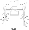
- FIG. 20 illustrates, in side view, the portion of the clamp body and rail of FIG. 18 with the clamp body and rail body engaged and secured together.
- FIG. 21 illustrates, in side view, a portion of the clamp body of FIG. 10 engaging the upper portion of the rail of FIG. 7 .
- FIG. 22 illustrates, in side view, the portion of the clamp body portion and rail of FIG. 21 with the clamp body and rail engaged and secured together.
- FIG. 23 illustrates, in exploded isometric view, an L-foot adapter assembly of the present disclosure.
- FIG. 24 illustrates a section view of an L-foot adapter body of the L-foot adapter assembly of FIG. 23 .
- FIG. 25 illustrates a section view of an L-foot adapter body of the L-foot adapter assembly of FIG. 26 .
- FIG. 26 illustrates, in exploded isometric view, an alternative version of an L-foot adapter assembly of the present disclosure.
- FIG. 27 illustrates, in side view, the rail of FIG. 4 , L-foot assembly of FIG. 2 , and L-foot adapter assembly of FIG. 23 with the rail being snapped into the L-foot adapter body.
- FIG. 28 illustrates, in side view, the rail, L-foot assembly and L-foot adapter assembly of FIG. 27 , with the rail being rotated in the L-foot adapter body.
- FIG. 29 illustrates, in side view, the rail, L-foot assembly and L-foot adapter assembly of FIG. 27 with the rail and L-foot adapter assembly extended upward with respect to the L-foot assembly.
- FIG. 30 illustrates, in side view, an enlarged portion of FIG. 29 , to illustrate how the rail is secured to the L-foot adapter body.
- FIG. 31 illustrates, in isometric view, an enlarged portion of the solar PV system similar to FIG. 2 , cut along section lines 2 - 2 in FIG. 1 , showing how the L-foot adapter assembly of FIG. 26 can be mounted directly to a trapezoidal roof.
- FIG. 32 illustrates, in isometric view, the enlarged portion of FIG. 31 .
- FIG. 33 illustrates, in isometric view, a solar PV system mounted directly to a trapezoidal roof using the L-foot adapter assembly of FIG. 26 and with the solar panels oriented in landscape mode.
- FIG. 34 illustrates, in side view, a trapezoidal metal roof with wood roof decking in cutaway view, to show the L-foot adapter assembly secured to a roof rafter and with the rail exploded away from the L-foot adapter.
- FIG. 35 illustrates, in exploded view isometric view, a rail splice assembly of the present disclosure that can engage the rail of FIG. 4 .
- FIG. 36 illustrates, in exploded view isometric view, an alternative version of a rail splice assembly of the present disclosure that can engage the rail of FIG. 7 .
- FIG. 37 illustrates, in side view, the rail splice of FIG. 35 .
- FIG. 38 illustrates, in side view, a rail splice of FIG. 36 .
- FIG. 39 illustrates, in isometric view, two rails exploded away from the rail splice assembly.
- FIG. 40 illustrates, in isometric view, the rails and rail splice assembly of FIG. 39 with one of the rails secured to the rail splice assembly.
- FIG. 41 illustrates in isometric view, the rails and rail splice assembly of FIG. 39 with both of the rails secured to the rail splice assembly.
- FIG. 42 illustrates, in side view, the rails and rail splice assembly of FIG. 41 .
- FIG. 43 illustrates, in exploded and isometric view, an end clamp of the present disclosure for mounting solar panels in portrait mode.
- FIG. 44 illustrates, in exploded and isometric view, the end clamp of FIG. 43 where the spring is replaced by a washer.
- FIG. 45 illustrates, in exploded and isometric view, the mid clamp of the present disclosure for mounting solar panels in portrait mode.
- FIG. 46 illustrates, in exploded isometric view, an alternative version of the mid clamp for mounting solar panels in portrait mode.
- FIG. 47 illustrates, in side view, the body that is common to the end clamps and mid clamps FIGS. 43 - 46 .
- FIG. 48 illustrates, in side view, a portion of the body of FIG. 47 enlarged magnify the bonding block mounting portion.
- FIG. 49 illustrates, in side view, the body of FIG. 47 mounted together with the bonding block, with portions of the body hidden from view by the bonding block are illustrated as dashed lines.
- FIG. 50 illustrates, in bottom isometric view, the body and the bonding block of FIG. 49 .
- FIG. 51 illustrates, in front view, the end clamp of FIG. 43 securing a solar panel to a rail, with dashed lines representing hidden lines.
- FIG. 52 illustrates, in side view, of FIG. 51 .
- FIG. 53 illustrates, in front view, the mid clamp of FIG. 45 securing two solar panel to a rail with dashed lines representing hidden lines.
- FIG. 54 illustrates, in side view, of FIG. 53 with dashed lines representing hidden lines.
- FIG. 55 illustrates, in top isometric view, a portion of the mid clamp of FIG. 53 with one of the solar panels removed to show the relationship between the mid clamp, the bonding block, bonding pins, and rail slot.
- FIG. 56 illustrates, in top isometric view, portions of two adjacent solar panels where the solar panels are being secured to the rail by the mid clamp of FIG. 46 .
- FIG. 57 illustrates, in front view, the mid clamp of FIG. 46 securing two solar panels to a rail, with dashed lines representing hidden lines.
- FIG. 58 illustrates, in side view, a portion of FIG. 57 with dashed lines representing hidden lines.
- FIG. 59 illustrates, in top isometric view, a portion of FIG. 57 with one of the solar panels removed to show the relationship between the mid clamp, the bonding block, and rail slot.
- FIG. 60 illustrates, in exploded and isometric view, a bottom clamp of the present disclosure.
- FIG. 61 illustrates, in isometric view a portion of solar PV system with the front of the solar panel cutaway along section lines 2 - 2 in FIG. 1 , to reveal a bottom clamp of FIG. 60 .
- FIG. 62 illustrates, in front view, the portion of the solar PV system of FIG. 61 with the bottom clamp shown unclamped to the return frame to of the solar panel frame.
- FIG. 63 illustrates, in front view, the portion of the solar PV system of FIG. 61 with the bottom clamp shown clamped to the return frame to of the solar panel frame.
- FIG. 64 illustrates, in side view, a portion of the solar PV system of FIGS. 61 63 extending to one end of the solar panel frame and with portions of the solar panel frame and the bottom clamp that are hidden from view illustrated in dashed lines.
- FIG. 65 illustrates, in exploded and isometric view, a shared-rail end clamp of the present disclosure for mounting solar panels in landscape mode.
- FIG. 66 illustrates, in exploded and isometric view, a shared-rail mid clamp of the present disclosure for mounting solar panels in landscape mode.
- FIG. 67 illustrates, in side view, the shared-rail end clamp of FIG. 65 .
- FIG. 68 illustrates, in side view, the shared-rail mid clamp of FIG. 66 .
- FIG. 69 illustrates, in side view, a portion of a solar PV system illustrating a solar panel secured to a rail, L-foot adapter assembly, and L-foot assembly by the shared-railed end clamp of FIG. 65 .
- FIG. 70 illustrates, in side view, a portion of a solar PV system illustrating solar panels secured to a rail, L-foot adapter assembly, and L-foot assembly by the shared-railed mid clamp of FIG. 66 .
- FIG. 71 illustrates an enlarged portion of the solar PV system similar to FIG. 2 , cutaway along section lines 2 - 2 in FIG. 1 , except an L-foot and flashing assembly is used in place of the L-foot assemblies of FIG. 2 .
- FIG. 72 illustrates a solar PV system similar to FIG. 3 except L-foot and flashing assemblies of FIG. 71 are used in place of the L-foot assemblies of FIG. 3 .
- FIG. 73 illustrates an enlarged portion of FIG. 71 , also cutaway along section lines 2 - 2 of FIG. 1 , with the rail, L-foot adapter assembly, end clamp, and solar panel, together extended upward along the L-foot and flashing assembly.
- FIG. 74 illustrates the rail, L-foot adapter assembly, end clamp, and solar panel of FIG. 73 , together extended downward along the L-foot and flashing assembly.
- FIG. 75 illustrates, in exploded and isometric view, the L-foot and flashing assembly together with the L-foot adapter assembly of FIGS. 71 - 74 .
- FIG. 76 illustrates an enlarged portion of the solar PV system similar to FIG. 2 , and cutaway along section lines 2 - 2 in FIG. 1 , except an L-foot assembly with two degrees of freedom is used in place of the L-foot assembly of FIG. 2 .
- FIG. 77 illustrates a solar PV system similar to FIG. 3 except the L-foot assemblies of FIG. 76 replaces the L-foot assemblies of FIG. 3 .
- FIG. 78 illustrates an enlarged portion of FIG. 77 with the rail, L-foot adapter assembly, end clamp, and solar panel, together extended forward and upward along the L-foot assembly.
- FIG. 79 illustrates the rail, L-foot adapter assembly, end clamp, and solar panel of FIG. 78 , together extended rearward and upward along the L-foot assembly.
- FIG. 80 illustrates the rail, L-foot adapter assembly, end clamp, and solar panel assembly of FIG. 78 extended rearward and downward along the L-foot assembly.
- FIG. 81 illustrates an exploded view of the L-foot assembly and the L-foot adapter of 76 - 80 .
- FIG. 82 illustrates, in exploded and isometric view, the L-foot assembly and L-foot adapter assembly used in FIGS. 1 - 3 , 17 , 27 - 29 , 51 - 55 , 57 - 59 , 61 - 64 , 69 , and 70 .
- FIG. 83 illustrates, in exploded and isometric view, the L-foot assembly and L-foot adapter assembly with the L-foot assembly being similar to FIG. 82 but with an alternative hole pattern.
- FIG. 84 illustrates, in side view, an alternative rail of the present disclosure.
- FIG. 85 illustrates an enlarged view an upper detented portion located on the left side of FIG. 84 .
- FIG. 86 illustrates an enlarged view of a lower detented portion located on the left side of FIG. 84 .
- FIG. 87 illustrates the rail of FIG. 84 with a portion of an alternative panel clamp.
- FIG. 88 illustrates an enlarged view of an alternative clamping portion.
- FIG. 89 illustrates a clamp body that utilizes the alternative clamping portion of FIG. 88 with the clamping body secured to the rail of FIG. 4 .
- top,” “bottom,” “front,” “rear,” and “side,” are from the perspective of a person standing in front of a solar PV system. Specific dimensions are intended to help the reader understand the scale and advantage of the disclosed material. Dimensions given are typical and the claims are not limited to the recited dimensions. Ordinals such as “first,” “second,” or “third,” are used in this Description and in the Claims to differentiate between similarly-named parts and do not imply a particular order, preference, or importance. For the purpose of this disclosure, multiple instances of equivalent parts are often differentiated by a “prime” symbol for clarity when discussing the parts. “Optional” or “optionally” is used throughout this disclosure to describe features or structures that are optional.
- the inventors developed a solar panel racking system and associated devices with advantages over previous such systems and devices. Examples utilizing principals of the inventors' solar panel racking system and associated devices are described in this Description. These examples utilize components that can be snapped together or slide together. This reduces the number of threaded fasteners used in a typical solar PV panel system installation, thereby reducing labor costs. Utilizing a common set of components across many installation environments and implementations can reduce logistics costs.
- FIGS. 4 - 42 discuss examples a common set of components that includes rails, L-foot adapters, and rail splices.
- Three examples of rails are illustrated: rail 12 of FIG. 4 , rail 13 of FIG. 7 , and rail 97 of FIG. 84 .
- rail 13 is wider than rail 12
- the upper portion of the rails is structured to accept a common set of panel clamps.
- FIGS. 10 , 12 - 14 , 17 , 18 , and 20 illustrate how various panel clamps can attach and secure to rail 12 . These same panel clamps can also attach and secure to rail 13 .
- FIGS. 21 and 22 illustrate an example of a panel clamp securing to rail 13 .
- Two examples of L-foot adapter assemblies are discussed in FIGS.
- FIGS. 35 - 42 Two examples of rail splice assemblies are discussed in FIGS. 35 - 42 : rail splice assembly 21 in FIG. 35 for use with rail 12 of FIG. 4 and rail splice assembly 22 in FIG. 36 for use with rail 13 of FIG. 7 .
- FIGS. 1 and 2 illustrate solar panel racking system 10 utilized in solar PV panel system 20 with solar panel 23 and solar panel 24 mounted in portrait mode.
- FIG. 2 shows a portion of solar panel racking system 10 with a common set of components (i.e. rail 12 , L-foot adapter assembly 18 , and rail splice assembly 21 ).
- FIG. 3 illustrates solar panel racking system 10 used in solar PV panel system 30 with solar panel 23 and solar panel 24 mounted in landscape mode.
- Solar panel racking system 10 in FIG. 3 also utilizes the same common set of components (i.e. rail 12 , L-foot adapter assembly 18 , and rail splice assembly 21 ).
- FIGS. 43 - 64 illustrate panel clamps that can be used when solar panels are to be mounted in portrait mode.
- Examples of portrait-mode end clamps include end clamp 25 in FIG. 43 and end clamp 26 in FIG. 44 .
- Examples of portrait-mode mid clamps include mid clamp 27 of FIG. 45 and mid clamp 28 of FIG. 46 .
- An example of a portrait-mode bottom clamp is illustrated in FIG. 60 as bottom clamp 29 .
- FIGS. 65 - 70 illustrate panel clamps that can be used to mount solar panels in landscape mode with end clamp 31 illustrated in FIG. 65 and mid clamp 32 illustrated in FIG. 66 .
- FIGS. 71 - 83 illustrates four examples of L-foot assemblies.
- L-foot assembly 33 is illustrated in FIGS. 71 - 75
- L-foot assembly 34 is illustrated in FIGS. 76 - 81
- L-foot assembly 35 is illustrated in FIG. 82
- L-foot assembly 36 is illustrated in FIG. 83 .
- the system can optionally be mounted without an L-foot assembly.
- FIGS. 31 - 34 illustrate the solar panel racking system 10 mounted with the L-foot adapter assembly 17 mounted directly to a metal roof 37 .
- the rails, panel clamps, and L-foot adapters are structured so that they can be snapped or slid together without the use of tools. With rails often reaching over 4 meters (13.1 ft.), snapping together these components has an advantage over sliding. This is especially true for mid clamp and L-foot adapters, as these components can be located anywhere along the length of the rail.
- rail 12 includes a pair of upper detented portions, upper detented portion 12 a and upper detented portion 12 b located on rail side 12 c and rail side 12 d , respectively, on the upper region of the rail (i.e., upper half of the rail as measured heightwise).
- the pair of rail sides, rail side 12 c and rail side 12 d form opposing outside-facing surfaces of rail 12 .
- the pair of rail sides i.e., rail side 12 c and rail side 12 d
- FIG. 5 illustrates upper detented portion 12 a in more detail.
- Upper detented portion 12 a includes upper first sloped surface 12 f and upper second sloped surface 12 g .
- Upper first sloped surface 12 f projects upward and inward at an angle A 1 with respect to its corresponding rail side, rail side 12 c .
- Upper second sloped surface 12 g projects downward and outward with respect to upper first sloped surface 12 f .
- Upper second sloped surface 12 g makes an angle A 2 with respect to rail side 12 c . Angle A 1 and A 2 are illustrated as acute (i.e., less than 90°).
- Upper first sloped surface 12 f is shown positioned above upper second sloped surface 12 g .
- Upper first sloped surface 12 f and upper second sloped surface 12 g are positioned between two portions of their corresponding rail side, rail side 12 c .
- FIG. 7 illustrates rail 13 that has a wider body width than rail 12 of FIG. 4 .
- Rail 12 of FIG. 4 has a body width of width D 2 between rail side 12 c and rail side 12 d located below lower detented portion 12 n and lower detented portion 12 o .
- Rail 13 of FIG. 7 has a body width of width D 3 between rail side 13 c and rail side 13 d located below lower detented portion 13 n and lower detented portion 13 o .
- Rail 12 and Rail 13 both can share the same upper body widths of width D 1 (i.e., the width between rail sides where they engage their respective upper detented portions). This allows both rails to engage a common set of panel clamps as the panel clamps engage the upper detented portions.
- rail 13 includes a pair of upper detented portions, upper detented portion 13 a and upper detented portion 13 b , located on the upper region of rail side 13 c and rail side 13 d , respectively and on the upper region of rail (i.e., upper half of the rail as measured heightwise).
- the pair of rail sides, rail side 13 c and rail side 13 d form opposing outside-facing surfaces of the rail.
- the upper region of the pair of rail sides i.e., rail side 13 c and rail side 13 d
- FIG. 8 illustrates upper detented portion 13 a in more detail.
- Upper detented portion 13 a includes upper first sloped surface 13 f and upper second sloped surface 13 g .
- Upper first sloped surface 13 f projects upward and inward at an angle A 1 with respect to its corresponding rail side, rail side 13 c .
- Upper second sloped surface 13 g projects downward and outward with respect to upper first sloped surface 13 f .
- Upper second sloped surface 13 g makes an angle A 2 with respect to its corresponding rail side, rail side 13 c .
- Angle A 1 and A 2 is illustrated as acute (i.e., less than 90°).
- Upper first sloped surface 13 f being positioned above upper second sloped surface 13 g and both upper first sloped surface 13 f and upper second sloped surface 13 g are positioned between two portions of rail side 13 c .
- FIGS. 10 , 12 - 14 , 17 , 18 and 20 show examples of how various panel clamps interact with rail 12 and secure to upper detented portion 12 a and upper detented portion 12 b positioned on opposing sides and on opposing outside-facing surfaces of rail 12 .
- the panels clamps illustrated in FIGS. 10 , 12 - 14 , 17 , 18 and 20 can similarly be secured to upper detented portion 13 a and upper detented portion 13 b positioned on opposing sides and on opposing outside-facing surfaces of rail 13 of FIG. 7 .
- FIGS. 21 and 22 illustrate how clamp body 38 would interact and be secured to rail 13 .
- FIG. 10 also illustrates clamp body 38 with rail 12 .
- Clamp body 38 is common to end clamp 25 , end clamp 26 , mid clamp 27 , and mid clamp 28 of FIGS. 43 , 44 , 45 , and 46 , respectively.
- FIGS. 13 , 14 , and 17 illustrates clamp body 39 with rail 12 .
- Clamp body 39 is part of bottom clamp 29 discussed for FIGS. 60 - 64 .
- Clamp body 41 and rail 12 are illustrated together in FIGS. 18 and 20 .
- Clamp body 41 is common to end clamp 31 of FIG. 65 and mid clamp 32 of FIG. 66 .
- Clamping portion 38 a is illustrated in FIG. 11
- clamping portion 39 a is illustrated in FIG. 15
- clamping portion 39 b is illustrated in FIG. 16
- clamping portion 41 a is illustrated in FIG. 19 .
- clamping portion 38 a and clamping portion 38 b of clamp body 38 slide downward under tension along the upper portions of rail side 12 c and rail side 12 d , respectively.
- the pair of clamp body arms, clamp body arm 38 c and clamp body arm 38 d of clamp body 38 bends outward under spring tension as clamp body 38 is pushed downward.
- Clamp body 38 is typically made of a material that exhibits spring tension such as steel or aluminum.
- clamping portion 38 a and clamping portion 38 b of clamp body 38 are snapped or rotated into upper detented portion 12 a and upper detented portion 12 b , respectively of rail 12 .
- the pair of clamp body arms, clamp body arm 38 c and clamp body arm 38 d spring back inward into upper detented portion 12 a and upper detented portion 12 b , respectively, from their position in FIG. 10 .
- Clamping portion 38 a , clamping portion 38 b , upper detented portion 12 a , and upper detented portion 12 b are so shaped, to prevent upward movement of clamp body 38 once respective clamping portions and upper detented portions are engaged.
- First sloped surface 38 f of FIG. 11 and upper first sloped surface 12 f of FIG. 5 can be angle upward and inward at the same angle, angle A 1 .
- first sloped surface 38 f and upper first sloped surface 12 f form interlocking surfaces to prevent upward movement.
- Base 38 e of clamp body 38 engages rail top 12 e of rail 12 to prevent upward movement.
- Second sloped surface 38 g of FIG. 11 and upper second sloped surface 12 g of FIG. 5 can be angled downward and outward at the same angle A 2 . Referring to FIG. 12 , this allows upper second sloped surface 12 g and second sloped surface 38 g to rest against one another.
- Upper detented portion 12 b and clamping portion 38 b are similarly configured. This allows clamp body arm 38 c and clamp body arm 38 d to rest directly against rail side 12 c and rail side 12 d , respectively.
- rail 12 optionally can include rail slot 12 h that runs lengthwise within the top of rail 12 .
- rail slot 12 h can be sized to engage a bonding assembly that can electrically bond clamp body 38 to rail 12 .
- bonding assembly 42 can include bonding block 43 , bonding pin 44 , and bonding pin 45 , of which bonding pin 44 is visible in the FIGS. 10 and 12 and bonding pin 45 is hidden from view.
- Bonding block 43 is secured to clamp body 38 by spring clip 38 i and spring clip 38 j projecting downward from clamp body 38 .
- the bonding block assembly will be discussed in more detail later in this disclosure.
- bottom clamp 29 can be secured to rail 12 using a similar principle.
- Clamping portion 39 a and clamping portion 39 b stays secured to upper detented portion 12 a and upper detented portion 12 b , respectively in the same way as described above for FIG. 12 .
- first sloped surface 39 f and upper first sloped surface 12 f form interlocking surfaces to prevent upward movement and slippage.
- first sloped surface 39 f has an acute angle of angle A 1 with respect to clamp body arm 39 c , which matches angle A 1 of upper detented portion 12 a of FIG. 5 .
- second sloped surface 39 g and upper second sloped surface 12 g can be angled downward and outward at the same angle so that the two surfaces rest against one another and to allow clamp body arm 39 c to rest directly against rail side 12 c .
- second sloped surface 39 g has an acute angle A 2 with respect to clamp body arm 39 c , which matches angle A 2 of upper detented portion 12 a of FIG. 5 .
- base 39 e of clamp body 39 engages rail top 12 e of rail 12 to place a limit on downward movement.
- clamping portion 39 b of adjustment support structure 39 p includes first sloped surface 39 m that forms interlocking surfaces with first sloped surface 12 m to prevent upward movement.
- first sloped surface 39 m has an acute angle of angle A 1 with respect to rail contact surface 39 d which matches angle A 1 of upper detented portion 12 a of FIG. 5 .
- second sloped surface 39 r and upper second sloped surface 12 r can be angled downward and outward at the same angle so that the two surfaces rest against one another and to allow rail contact surface 39 d of the adjustment support structure 39 p to rest directly against rail side 12 d .
- second sloped surface 39 n has an acute angle A 2 with respect to rail contact surface 39 d , which matches the angle of upper second sloped surface 12 r of FIG. 14 .
- clamp body 39 can be rotated. As the clamp body 39 is rotated, clamping portion 39 a will then slide downward along rail side 12 c of rail 12 . The clamp body arm 39 c and clamping portion 39 a will be pushed outward by the rail side 12 c . Rail contact surface 39 d is rotated against rail side 12 d . Base 39 e pivots against rail top 12 e . Referring to FIG. 14 , clamping portion 39 a is snapped into upper detented portion 12 a.
- FIG. 17 another way to install and secure bottom clamp 29 to rail 12 is to slide it into side of rail 12 .
- Clamping portion 39 a and clamping portion 39 b are slid into upper detented portion 12 a and upper detented portion 12 b , respectively from the edge of rail 12 .
- clamp body 39 will resist upward movement as described above.
- FIGS. 65 and 66 are secured to rail 12 of FIG. 4 by use of clamp body 41 illustrated in FIGS. 18 and 20 using the same principle as discussed for FIGS. 10 - 12 .
- clamping portion 41 a and clamping portion 41 b slide downward under tension along the upper portions of rail side 12 c and rail side 12 d , respectively.
- the pair of clamp body arms, clamp body arm 41 c and clamp body arm 41 d , of clamp body 41 bend outward under spring tension as clamp body 41 is pushed downward.
- clamping portion 41 a and clamping portion 41 b are slid into upper detented portion 12 a and upper detented portion 12 b , respectively, of rail 12 , the pair of clamp body arms, clamp body arm 41 c and clamp body arm 41 d , spring back inward into the detented portions.
- Clamping portion 41 a , clamping portion 41 b , upper detented portion 12 a , and upper detented portion 12 b are shaped and angled that once engaged, upward movement of clamp body 41 is prevented.
- First sloped surface 41 f and upper first sloped surface 12 f form interlocking surfaces to prevent upward movement and slippage. Referring to FIG.
- first sloped surface 41 f has an acute angle, angle A 1 , with respect to clamp body arm 41 c , which matches angle A 1 of upper detented portion 12 a of FIG. 5 .
- base 41 e of clamp body 41 engages rail top 12 e of rail 12 to prevent upward movement.
- First sloped surface of clamping portion 41 b is similarly angled to prevent upward movement against upper detented portion 12 b .
- Second sloped surface 41 g and upper second sloped surface 12 g can be angled downward and outward at the same angle so that the two surfaces rest against one another and to allow clamp body arm 41 c to rest directly against rail side 12 c .
- second sloped surface of clamping portion 41 b is similarly angled to allow clamp body arm 41 d to rest directly against rail side 12 d .
- second sloped surface 41 g has an acute angle A 2 with respect to clamp body arm 41 c , which matches angle A 2 of upper second sloped surface 12 g of FIG. 5 .
- Clamp body 38 , clamp body 39 , and clamp body 41 of FIGS. 10 , 14 , and 18 , respectively can also engage rail 13 of FIG. 7 because of the common upper structure that rail 13 shares with rail 12 of FIG. 4 , as previously discussed.
- clamp body 38 engages rail 13 .
- clamping portion 38 a and clamping portion 38 b of clamp body 38 slide downward under tension along the upper portions of rail side 13 c and rail side 13 d , respectively.
- the pair of clamp body arms, clamp body arm 38 c and clamp body arm 38 d of clamp body 38 bend outward under spring tension as clamp body 38 is pushed downward.
- clamping portion 38 a and clamping portion 38 b of clamp body 38 are snapped or rotated into upper detented portion 13 a and upper detented portion 13 b , respectively of rail 13 .
- the pair of clamp body arms, clamp body arm 38 c and clamp body arm 38 d will then spring back inward into the upper detented portions.
- Clamping portion 38 a and clamping portion 38 b and upper detented portion 13 a and upper detented portion 13 b are shaped as previously described in FIG. 12 .
- First sloped surface 38 f and upper first sloped surface 13 f form interlocking surfaces to prevent upward movement and slippage.
- Rail 13 can include rail slot 13 h that runs lengthwise along rail top 13 e .
- Rail slot 13 h can be sized to engage a bonding assembly 42 that can electrically bond clamp body 38 to rail 13 in a similar manner as previously discussed for FIG. 12 .
- rail 12 includes lower detented portion 12 n and lower detented portion 12 o for engaging L-foot adapter assembly 18 of FIG. 23 .
- lower detented portion 12 n and lower detented portion 12 o are formed and positioned in a lower region of rail side 12 c and rail side 12 d , respectively (i.e., the lower half of the rail as measured heightwise).
- rail 13 includes lower detented portion 13 n and lower detented portion 13 o for engaging a version of L-foot adapter assembly 18 of FIG. 23 .
- L-foot adapter body 51 includes an interior width D 4 .
- the interior width D 4 of FIG. 24 would equal width D 2 of FIG. 4 .
- the interior width D 4 of FIG. 24 would equal width D 3 of FIG. 7 .
- lower detented portion 12 n includes lower first sloped surface 12 p that extends inward and downward from rail side 12 c and a lower second sloped surface 12 q that extends upward and outward from the bottom of lower first sloped surface 12 p .
- Lower first sloped surface 12 p extends at an acute angle with respect to rail side 12 c of angle A 4 .
- Lower second sloped surface 12 q has an acute angle, angle A 3 , with respect to rail side 12 c .
- lower detented portion 12 o similarly includes lower first sloped surfaces and lower second sloped surfaces as described for lower detented portion 12 n of FIG. 6 .
- Lower detented portion 13 n and lower detented portion 13 o of FIG. 7 are similarly structured to lower detented portion 12 n and lower detented portion 12 o of FIG. 4 .
- lower detented portion 13 n includes lower first sloped surface 13 p that extends inward and downward from rail side 13 c and lower second sloped surface 13 q that extends upward and outward from the bottom of lower first sloped surface 13 p .
- Lower first sloped surface 13 p extends at an acute angle with respect to rail side 13 c of angle A 4 .
- Lower second sloped surface 13 q has an acute angle of angle A 3 with respect to rail side 12 c .
- Lower detented portion 13 o similarly includes first sloped surfaces and second sloped surfaces as described for lower detented portion 13 n.
- FIGS. 27 - 30 illustrate how rail 12 engages L-foot adapter body 51 of L-foot adapter assembly 18 and L-foot adapter assembly 18 engaging L-foot assembly 35 .
- FIGS. 23 and 24 describe L-foot adapter assembly 18 and L-foot adapter body 51 , respectively.
- This description that follows for rail 12 of FIG. 4 and L-foot adapter assembly 18 of FIGS. 27 - 30 can equally apply to rail 13 of FIG. 7 ; the difference being that width D 4 of L-foot adapter body 51 of FIG. 24 would equal width D 3 of FIG. 7 instead of width D 2 of FIG. 4 .
- L-foot adapter assembly 18 can include L-foot adapter body 51 , threaded fastener 52 , and optionally one or more washers. Illustrated are washer 53 and washer 54 . Washer 53 is illustrated as an internal toothed washer. Other types of lock washers can be substituted such as a split lock washer or external toothed washer. Washer 54 is illustrated as a flat washer. Other types of plain washers can be substituted such as fender washer, shoulder washer, or c-washer. The functionality of one or either of the illustrated washers can optionally be built into threaded fastener 52 .
- threaded fastener 52 engages aperture 51 s and aperture 51 t of L-foot adapter body 51 .
- Aperture 51 t is typically threaded to threadedly engage and secure threaded portion 52 a ( FIG. 23 ) of threaded fastener 52 ( FIG. 23 ).
- aperture 51 s is typically unthreaded to allow fastener body 52 b to turn freely.
- rail 12 can snap or be rotated into L-foot adapter body 51 of L-foot adapter assembly 18 .
- Rail 12 can be snapped or rotated into L-foot adapter assembly 18 while it is mounted and secured to L-foot assembly 35 .
- FIG. 27 rail 12 is being snapped into L-foot adapter body 51 .
- FIG. 28 rail 12 is being rotated into L-foot adapter body 51 .
- the L-foot adapter body 51 is shown as a one-piece body with L-foot adapter side 51 d thinner and more flexible with the L-foot adapter side 51 c .
- the rails and L-foot adapter assemblies of the present disclosure can be snapped or rotated into L-foot adapter bodies independent of whether or not L-foot adapter assemblies are mounted to an L-foot assemblies or other mounting structures.
- L-foot adapter assembly 18 is mounted loosely to L-foot assembly 35 .
- L-foot adapter assembly 18 can be moved to any position along L-foot assembly 35 then tightened into place. Because of this, the installer could choose to preassemble L-foot adapter assembly 18 to L-foot assembly 35 . Alternatively, the installer could preassemble rail 12 to L-foot adapter assembly 18 and then attach the rail and L-foot adapter assembly combination to L-foot assembly 35 . Having these options allows for more flexibility during installation. For example, rail 12 can be preassembled to L-foot adapter assembly 18 on the roof, on the ground, or even at the installer's shop. The resulting assembly can then be secured to L-foot assembly 35 .
- L-foot adapter body 51 includes clamping portion 51 a extending upward from the top of L-foot adapter side 51 c and clamping portion 51 b extending upward from the top of L-foot adapter side 51 d .
- Clamping portion 51 a and clamping portion 51 b include first sloped surface 51 p and first sloped surface 51 u , respectively.
- First sloped surface 51 p and first sloped surface 51 u extend downward and inward from the top of L-foot adapter side 51 c and the top of L-foot adapter side 51 d , respectively.
- Clamping portion 51 a and clamping portion 51 b include second sloped surface 51 q and second sloped surface 51 v , respectively.
- Second sloped surface 51 q and second sloped surface 51 v extend upward and outward from first sloped surface 51 p and first sloped surface 51 u , respectively.
- First sloped surface 51 p and first sloped surface 51 u make an angle A 4 with respect to L-foot adapter side 51 c and L-foot adapter side 51 d , respectively.
- Second sloped surface 51 q and second sloped surface 51 v make an angle A 3 with respect to L-foot adapter side 51 c and L-foot adapter side 51 d , respectively. Referring to FIG. 30 , this allows first sloped surface 51 p and first sloped surface 51 u to planarly engage lower first sloped surface 12 p and lower first sloped surface 12 u , respectively of rail 12 .
- second sloped surface 51 q and second sloped surface 51 v engage lower second sloped surface 12 q and lower second sloped surface 12 v , respectively, of rail 12 .
- the downward and inward slope of second sloped surface 51 q and second sloped surface 51 v combined with the complementary upward and outward slope of lower second sloped surface 12 q and lower second sloped surface 12 v , respectively, create “catches” for rail 12 and cause rail 12 to resist upward movement.
- the downward and inward slope of lower first sloped surface 12 p and lower first sloped surface 12 u helps to allow lower rail side 12 w and lower rail side 12 x to slide or rotate into L-foot adapter side 51 w and L-foot adapter side 51 x , respectively.
- L-foot adapter side 51 d being cross-sectionally thinner than L-foot adapter side 51 c in combination with the L-foot adapter body 51 having a one-piece body.
- FIGS. 27 and 28 how rail 12 engages L-foot adapter body 51 .
- L-foot adapter side 51 d bends outward as rail 12 is either snapped into place ( FIG. 27 ) or rotated into place ( FIG. 28 ).
- L-foot adapter side 51 c which is thicker and more rigid than L-foot adapter side 51 d , remains stationary.
- L-foot adapter body 51 is a one-piece body and L-foot adapter side 51 d is thinner than L-foot adapter side 51 c , it will bend from the force of the rail 12 being rotated or snapped into place. Referring to FIG. 29 , L-foot adapter side 51 d will spring back into its resting position and no longer bend outward after rail 12 is snapped into place. After threaded fastener 52 is tightened, L-foot adapter side 51 d becomes supported by L-foot 35 and increases resistance to the rail 12 from pulling upward away from the L-foot adapter assembly.
- flanged portion 51 y and flanged portion 51 z extending inward from L-foot adapter side 51 c and L-foot adapter side 51 d , respectively, support the rail bottom and prevent rail 12 from moving downward.
- Flanged portion 51 y and flanged portion 51 z are also illustrated in FIGS. 23 and 24 .
- tightening of threaded fastener 52 further prevents upward movement of rail 12 because L-foot 35 now supports L-foot adapter side 51 d .
- L-foot adapter side 51 d can no longer bend outward.
- FIG. 26 illustrates an alternative L-foot adapter assembly, L-foot adapter assembly 17 .
- L-foot adapter assembly 17 utilizes L-foot adapter body 57 .
- L-foot adapter body 57 can be constructed with the same or similar structure as L-foot adapter body 51 of FIG. 23 but with the addition of aperture 57 r .
- L-foot adapter assembly 17 can utilize threaded fastener 52 and the optional washers, washer 53 and washer 54 . Washer 53 and washer 54 can be the same or similar as those described for FIG. 23 . Referring to FIG.
- the structure of L-foot adapter body 57 can be identical with the structure of L-foot adapter body 51 of FIG. 24 .
- L-foot adapter assembly 17 of FIG. 26 can be used in place of L-foot adapter assembly 18 of FIG.
- FIGS. 31 - 34 metal roof 37 is illustrated as a trapezoidal roof.
- L-foot adapter assembly 17 can be mounted to other metal roofs as long as they include flat mounting suitable for mounting the assembly.
- FIGS. 31 and 32 show solar panel racking system 10 with solar panel 23 and solar panel 24 arranged in portrait mode with L-foot adapter assembly 17 attached directly to metal roof 37 (solar panel 24 is not shown in FIG. 32 ).
- FIG. 33 shows solar panel racking system 10 with solar panel 23 and solar panel 24 arranged in landscape mode with L-foot adapter assembly 17 attached directly to metal roof 37 .
- L-foot adapter assembly 17 is attached directly to metal roof 37 . Threaded fastener 58 engages rafter 61 through roof deck 60 .
- roof deck 60 is illustrated as plywood sheathing but other roof sheathings such as oriented strand board (OSB), solid wood joints, or multilayered materials such as ZIP SYSTEM® Roof Sheathing. ZIP SYSTEM® is a registered trademark of J.M. Huber Corporation. Because the clamping structure of L-foot adapter body 57 is the same or similar as the clamping structure of L-foot adapter body 51 ( FIG. 24 ) rail 12 can snap in or rotate into L-foot adapter body 57 as previously described.
- OSB oriented strand board
- rail 12 can snap in or rotate into L-foot adapter body 57 as previously described.
- Rail 12 of FIG. 4 includes a hollow interior extending between rail side 12 c and rail side 12 d of the pair of rail sides.
- rail 13 of FIG. 7 includes a hollow interior extending between rail side 13 c and rail side 13 d of the pair of rail sides.
- rail top 12 e , rail side 12 c , rail side 12 d , rail slot 12 h , and rail bottom 12 i form the perimeter boundary of the hollow interior of rail 12 .
- rail top 13 e , rail side 13 c , rail side 13 d , rail slot 13 h , and rail bottom 13 i form the perimeter boundary of the hollow interior of rail 13 .
- the hollow interiors of rail 12 and rail 13 have no internal support structure allowing for other structures to slide into rail 12 and rail 13 .
- Two examples of structures that can slide into hollow rails are rail splice assembly 21 of FIG. 35 and rail splice assembly 22 of FIG. 36 .
- Rail splice assembly 21 of FIG. 35 is sized and shaped to slide into rail 12 of FIG. 4 .
- Rail splice assembly 22 of FIG. 36 is sized and shaped to slide into the rail 13 of FIG. 7 .
- FIG. 37 illustrates the shape of rail splice body 62 .
- FIG. 38 illustrates the shape of rail splice body 70 . Referring to FIG.
- rail splice body 62 includes sidewall 62 a , sidewall 62 b , and aperture 62 c .
- Sidewall 62 a and sidewall 62 b extend downward from opposite sides of top wall 62 d to a bottom wall 62 e .
- Rail splice body 62 optionally includes projected portion 62 f and projected portion 62 g extending upward from opposite ends of top wall 62 d .
- sidewall 62 a and sidewall 62 b are sized and shaped to allow rail splice body 62 to slide within rail 12 .
- Projected portion 62 f and projected portion 62 g can optionally provide additional structural support.
- rail splice body 70 includes sidewall 70 a , sidewall 70 b , and aperture 70 c .
- Sidewall 70 a and sidewall 70 b extend downward from opposite sides of top wall 70 d to a bottom wall 70 e .
- Rail splice body 70 optionally includes projected portion 70 f and projected portion 70 g extending upward from opposite ends of top wall 70 d .
- Sidewall 70 a and sidewall 70 b are sized and shaped to allow rail splice body 70 to slide within rail 13 of FIG. 7 .
- Projected portion 70 f and projected portion 70 g can optionally provide additional structural support.
- rail splice assembly 21 includes rail splice body 62 , bonding pin 63 , bonding pin 64 , bonding pin 65 , bonding pin 66 , splice bracket 67 , threaded fastener 68 , and optionally, washer 69 .
- rail splice assembly 22 includes rail splice body 70 , and can also include bonding pin 63 , bonding pin 64 , bonding pin 65 , bonding pin 66 , splice bracket 67 , threaded fastener 68 , and optionally, washer 69 . The difference between rail splice assembly 21 of FIG. 35 and rail splice assembly 22 of FIG.
- splice bracket 67 includes aperture 67 a sized to receive and pass through a portion of threaded fastener body 68 a .
- threaded fastener body 68 a threadedly engages aperture 62 c located in sidewall 62 b of rail splice body 62 .
- bonding pin 63 , bonding pin 64 , bonding pin 65 , and bonding pin 66 are seated in blind hole 67 b , blind hole 67 c , blind hole 67 d , and blind hole 67 e , respectively, in splice bracket 67 .
- number of bonding pins and blind holes can be more or less than those shown. This can be determined by the bonding requirements and electrical conductivity of the material used.
- Splice bracket 67 can include a foot 67 f that projects inward toward rail splice body 62 ( FIG. 35 ) and rail splice body 70 ( FIG. 36 ) from the bottom of splice bracket 67 . Referring to FIG. 42 , foot 67 f is positioned to engage bottom of rail 12 and stabilize splice bracket 67 as it is tightened to rail 12 .
- FIGS. 39 - 41 show a typical assembly sequence of multiple rails using rail splice assembly 21 .
- rail splice assembly 21 is placed between rail 12 and rail 12 ′.
- Threaded fastener 68 is not fully tightened, but left loose enough to allow rail 12 and rail 12 ′ to engage rail splice body 62 , slide past splice bracket 67 and slide past bonding pin 63 , bonding pin 64 , bonding pin 65 , and bonding pin 66 .
- Bonding pin 63 , bonding pin 64 , bonding pin 65 , and bonding pin 66 are hidden from view in FIG. 39 but shown in FIG. 35 .
- FIG. 35 In FIG.
- rail splice body 62 is partially slid into the interior of rail 12 ′.
- Rail 12 ′ is slid under splice bracket 67 , bonding pin 63 , and bonding pin 64 . Bonding pin 63 and bonding pin 64 are hidden from view in FIG. 40 but shown in FIG. 35 .
- rail 12 remains unengaged with rail splice assembly 21 .
- rail 12 and rail 12 ′ are both assembled together.
- Rail splice body 62 is partially slid into the interior of rail 12 .
- Rail 12 is slid under splice bracket 67 and bonding pin 65 and bonding pin 66 .
- Bonding pin 65 and bonding pin 66 are hidden from view but shown in FIG. 35 .
- tightening of threaded fastener 68 will clamp splice bracket 67 to rail 12 and rail 12 ′ to rail splice body 62 and create a structurally rigid structure.
- Bonding pins not shown, will press against the rail and create an electrical path between rail 12 , rail 12 ′, and splice bracket 67 .
- the electrical path is created because bonding pin 63 , bonding pin 64 , bonding pin 65 , and bonding pin 66 have sharpened ends on both sides.
- blind hole 67 b This allows them to penetrate the oxide layer of blind hole 67 b , blind hole 67 c , blind hole 67 d , and blind hole 67 e and to penetrate the paint, finish coat, or oxide layer of rail 12 and rail 12 ′ of FIG. 39 in order to create an electrically conductive path.
- FIGS. 10 , 12 - 14 , 17 , 18 , and 20 demonstrated how various panel clamps interact with rail 12 and how they are secured to rail 12 . These panel clamps will now be discussed in more detail.
- End clamp 25 , end clamp 26 , mid clamp 27 , and mid clamp 28 of FIGS. 43 , 44 , 45 , and 46 respectively can share common components.
- End clamp 25 , end clamp 26 , mid clamp 27 , and mid clamp 28 of FIGS. 43 , 44 , 45 , and 46 respectively can include clamp body 38 , bonding block 43 , bonding pin 44 and bonding pin 45 , threaded fastener 49 , and optionally, lock washer 71 .
- Lock washer 71 is illustrated as an internal tooth lock washer, but other types of lock washers can be readily used; for example, external tooth lock washers, split ring lock washers, or high collar lock washers.
- Threaded fastener 49 threadedly engages threaded aperture 38 o in the clamp body 38 .
- FIG. 47 illustrates threaded aperture 38 o of clamp body 38 in more detail.
- bonding pin 44 and bonding pin 45 pass into apertures 43 a , 43 b , respectively, in bonding block 43 .
- bonding block 43 includes aperture 43 c that engages spring clip 38 i and spring clip 38 j projecting downward from clamp body 38 .
- spring clip 38 i and spring clip 38 j project downward from the bottom of support truss 38 p of clamp body 38 .
- spring clip 38 i and spring clip 38 j are approximately centered between clamping portion 38 a and clamping portion 38 b so that bonding block 43 will align and rest within a rail slot. Bonding block 43 is shown positioned within rail slot 12 h in FIGS. 51 - 55 .
- spring clip 38 i and spring clip 38 j can be seen in more detail.
- Spring clip 38 i includes first portion 38 q and second portion 38 s .
- Spring clip 38 j includes first portion 38 r and second portion 38 t , respectively.
- First portion 38 q and first portion 38 r project outward away from spring clip sides 38 u and spring clip sides 38 v respectively. They are illustrated as projecting outward approximately perpendicularly from spring clip sides 38 u and spring clip sides 38 v .
- an optionally planar bottom of bonding block 43 allows spring clip 38 i and spring clip 38 j to rest flatly against the bottom of the bonding block 43 .
- First portion 38 q and first portion 38 r can project out at other angles; for example, to match a non-planar bottom surface of bonding block 43 .
- second portion 38 s and second portion 38 t slope downward and inward from the end of first portion 38 q and first portion 38 r , respectively.
- this “barbed shape” of spring clip 38 i and spring clip 38 j allow them to be pushed into and through aperture 43 c and then spring out after being pushed through to prevent removal.
- End clamp 25 in FIG. 43 and end clamp 26 in FIG. 44 both include clamping member 72 .
- clamping member 72 is sized and shaped to engage the top of frame 23 a of solar panel 23 , engage clamp body 38 , and clamp solar panel 23 to rail 12 .
- tightening of threaded fastener 49 presses upper section 72 a of clamping member 72 against the top of frame 23 a .
- Clamping member 72 can tend to rotate backward toward clamp body 38 as it is tightened.
- Lower section 72 b of clamping member 72 which extends downward from upper section 72 a , will engage clamp body 38 and stabilize.
- bonding pin 44 and bonding pin 45 are pressed against rail slot 12 h , bonding pin 44 and bonding pin 45 break through the oxide or paint layer, and create an electrical bond between frame 23 a of solar panel 23 and rail 12 .
- bonding pin 44 is shown pressing against rail slot 12 h and frame 23 a of solar panel 23 .
- End clamp 26 of FIG. 43 and end clamp 26 of FIG. 44 can share the same elements expect a spring and washer. Washer 74 in end clamp 26 of FIG. 44 replaces spring 73 of end clamp 25 in FIG. 43 .
- Mid clamp 27 of FIG. 45 and end clamp 25 of FIG. 43 share the same elements except for their clamping members. These shared elements include spring 73 .
- mid clamp 27 includes clamping member 75 . Referring to FIG. 53 , tightening of threaded fastener 49 causes clamping member 75 to bear down on frame 23 a of solar panel 23 and frame 24 a of solar panel 24 .
- FIGS. 54 and 55 also show bonding pin 44 of mid clamp 27 engaging rail slot 12 h of rail 12 .
- clamp body 38 and portions of clamping member 75 are hidden behind solar panel 23 and represented by dashed lines.
- mid clamp 28 of FIG. 46 shares the same elements as end clamp 26 of FIG. 44 including washer 74 .
- Clamping member 76 is illustrated as a fender washer. Alternatively, the clamping member 76 can include serrated edges to create better grip against the top of the solar panel frame. Because clamping member 76 is circular, any rotation that may results from installation does not affect the final appearance or performance of clamping member 76 . This can be helpful when using a torque driver or other power tool to install mid clamp 28 .
- the resulting appearance of mid clamp 28 is illustrated in FIG. 56 where clamping member 76 and threaded fastener 49 can be seen and the remainder of mid clamp 28 is hidden below solar panel 23 and solar panel 24 .
- clamping member 76 can clamp solar panel 23 and solar panel 24 to rail 12 . Tightening of threaded fastener 49 causes clamping member 76 to bear down on frame 23 a of solar panel 23 and frame 24 a of solar panel 24 . This in turn, presses the bottom of frame 23 a and frame 24 a against bonding block 43 causing bonding pin 44 to press into frame 23 a , bonding pin 45 to press into frame 24 a , and both bonding pin 44 and bonding pin 45 to press into rail slot 12 h .
- Bonding pin 44 and bonding pin 45 break the paint or oxide layer of frame 23 a , frame 24 a , and rail slot 12 h , to electrically bond solar panel 23 and solar panel 24 to rail 12 .
- FIGS. 58 and 59 also show bonding pin 44 of mid clamp 28 engaging rail slot 12 h of rail 12 as clamping member 76 bears down on frame 23 a of solar panel 23 .
- clamp body 38 is hidden behind solar panel 23 and represented by dashed lines.
- solar panel 23 is removed to show portions of mid clamp 28 , clamping member 76 , clamp body 38 , bonding block 43 , and frame 24 a of solar panel 24 that would be otherwise hidden from view.
- bottom clamp 29 can include clamping member 77 , clamp body 39 , threaded adjuster 79 , pivoting body 80 , tensioning band 81 , and optionally, lock washer 82 .
- Clamping member 77 can include aperture 77 a that runs across and through clamping member 77 .
- Clamp body 39 includes base 39 e with side 39 h and side 39 i projecting upward from base 39 e and spaced apart sufficiently to receive clamping member 77 .
- Side 39 h and side 39 i include aperture 39 j and aperture 39 k , respectively.
- Aperture 39 j and aperture 39 k are sized to receive pivoting body 80 .
- Pivoting body 80 passes through aperture 39 j , 39 k of base 39 e and through aperture 77 a of clamping member 77 .
- Aperture 39 j and aperture 39 k can be aligned to position pivoting body 80 parallel to the plane of base 39 e .
- Pivoting body 80 is illustrated as a partially threaded bolt. Threaded portion 80 a threadedly engages aperture 39 k . Head portion 80 b of pivoting body 80 rests against side 39 i .
- Aperture 77 a of clamping member 77 is unthreaded to allow clamping member 77 to freely rotate about pivoting body 80 .
- Pivoting body 80 can typically be a cylindrical member held captive between the side 39 h and side 39 i .
- pivoting body 80 could be a cylindrical rod with apertures on opposing ends sized and shaped to receive cotter pins or dowel pins to hold the cylindrical rod to clamp body 39 .
- pivoting body 80 could be a cylindrical rod threaded on both ends with an unthreaded portion in the middle for engaging clamping member 77 . The threaded rod could be secured to side 39 h and side 39 i by nuts engaging the rod ends.
- clamping member 77 clamps solar panel 23 to rail 12 in FIGS. 62 and 63 .
- threaded adjuster 79 threadedly engages aperture 390 and engages lower portion 77 b of clamping member 77 .
- clamping member pivots about the pivoting body 80
- upper portion 77 c of clamping member 77 engages and clamps the return flange 23 b of frame 23 a of solar panel 23 .
- clamping pressure of clamping member 77 against return flange 23 b clamps the return flange 23 b to rail 12 .
- Tensioning band 81 is optionally used to create spring tension between clamp body 39 and clamping member 77 .
- clamping member 77 similarly engages return flange 23 b of frame 23 a of solar panel 23 and clamping return flange 23 b to rail 12 .
- threaded adjuster 79 can be accessed from the side of the solar panel. Referring to FIGS. 61 and 64 , threaded adjuster 79 is accessible under frame 23 a of solar panel 23 . The installer or service personnel can have clear access to threaded adjuster 79 . In FIG. 64 , return flange 23 b , portions of frame 23 a , and solar panel substrate 23 c that are hidden from view are illustrated in dashed lines.
- End clamp 31 illustrated in FIGS. 65 , 67 , and 69 and mid clamp 32 of FIGS. 66 , 68 , and 70 share a common set of components. These include threaded fastener 49 , spring 73 , clamp body 41 , bonding pin 44 and bonding pin 45 , and optionally, lock washer 71 .
- Clamp body 41 in FIGS. 65 , 67 , and 69 is optionally shown without bonding pin 44 and bonding pin 45 and without aperture 41 h and aperture 41 i that receive and pass through bonding pin 44 and bonding pin 45 , respectively, of FIGS.
- end clamp 31 includes clamping member 72 .
- mid clamp 32 includes clamping member 75 .
- threaded fastener body 49 a passes through aperture 72 c of clamping member 72 .
- threaded fastener body 49 a passes through aperture 75 c of clamping member 75 .
- threaded fastener body 49 a threadedly engages aperture 41 j of pedestal portion 41 m of clamp body 41 .
- Pedestal portion 41 m projects upward from base 41 e of clamp body 41 .
- the pair of clamp body arms, clamp body arm 41 c and clamp body arm 41 d project downward from clamp body 41 .
- Clamping portion 41 a and clamping portion 41 b extend from the ends of clamp body arm 41 c and clamp body arm 41 d , respectively, as previously discussed.
- tightening of threaded fastener 49 causes clamping member 75 to bear down on frame 23 a of solar panel 23 and frame 24 a of solar panel 24 , presses bonding pin 44 into frame 23 a , presses bonding pin 45 into frame 24 a , presses bonding pin 44 and bonding pin 45 against rail 12 , and thereby causes frame 23 a and frame 24 a to electrically bond to rail 12 . Additional electrical bonding can result from clamping portion 41 a and clamping portion 41 b digging into rail 12 and breaking through the paint or oxide layer.
- clamping member 72 is sized and shaped to engage the top of frame 23 a of solar panel 23 and to engage clamp body 41 .
- upper section 72 a of clamping member 72 presses against the top of frame 23 a .
- Clamping member 72 will tend to rotate backward toward clamp body 41 .
- Lower section 72 b of clamping member 72 which extends downward from upper section 72 a will engage clamp body 41 and stabilize.
- Clamp body 41 is shown without bonding pins or apertures to receive bonding pins.
- End clamp 31 can be used to create electrical bonding by including one or both of the apertures and bonding pins from FIG. 70 . This would electrically bond end clamp 31 to the rail as described for mid clamp 32 in the preceding paragraph.
- FIGS. 71 - 83 illustrate four examples of L-foot assemblies.
- L-foot assembly 33 is illustrated in FIGS. 71 - 75 .
- L-foot assembly 34 is illustrated in FIGS. 76 - 81 .
- L-foot assembly 35 is illustrated in FIG. 82 .
- L-foot assembly 36 which is a variation of L-foot assembly 35 , is illustrated in FIG. 83 .
- FIGS. 71 - 74 illustrate solar panel racking system 10 with L-foot assembly.
- L-foot assembly 33 includes roof flashing 83 that is typically used with a shingled roof, such as shingled roof 84 .
- Dashed lines in FIGS. 71 - 74 represent portions of flashing 83 that are hidden from view under the roof shingles of shingled roof 84 .
- solar panel 23 and solar panel 24 are mounted in portrait mode.
- solar panel 23 and solar panel 24 are mounted in landscape mode.
- L-foot assembly 33 is structured to allow solar panel racking system 10 to be adjusted upward and downward with respect to L-foot assembly 33 .
- FIG. 73 illustrates solar panel 23 , end clamp 25 , rail 12 , and L-foot adapter assembly 18 moved upward with respect to L-foot assembly 33 .
- FIG. 74 illustrates solar panel 23 , end clamp 25 , rail 12 , and L-foot adapter assembly 18 moved downward with respect to L-foot assembly 33 .
- L-foot assembly can include flashing 83 , L-foot 78 , gasket 56 , threaded fastener 58 , and washer 59 .
- Gasket 56 is received in recess 78 a within L-foot 78 .
- Flashing 83 includes raised portion 83 a that can create a watertight seal with gasket 56 .
- Threaded fastener 58 passes through aperture 78 b within base 78 c of L-foot 78 and through raised portion 83 a of flashing 83 .
- Threaded fastener 52 of L-foot adapter assembly 18 passes through washer 53 and washer 54 , through slot 78 d of upper portion 78 e of L-foot 78 and through L-foot adapter body 51 .
- Slot 78 d together with threaded fastener 52 allows L-foot adapter body 51 to move up and down.
- FIGS. 76 - 80 illustrate solar panel racking system 10 with L-foot assembly 34 .
- L-foot assembly 34 includes base 87 that can be used with a variety of different roof types including a shingled roof or metal roof.
- solar panel 23 and solar panel 24 are mounted in portrait mode.
- solar panel 23 and solar panel 24 are mounted in landscape mode.
- the front of solar panel 23 and solar panel 24 are cutaway cross-sectionally to expose L-foot assembly 34 that would normally be hidden from view if solar panel 23 and solar panel 24 were not cross-sectionally cutaway. Referring to FIGS.
- L-foot assembly 34 is structured to allow the solar panel racking system 10 to be adjusted forward and backward as well as upward and downward with respect to L-foot assembly 34 .
- L-foot assembly 34 can be helpful when mounting solar panels in landscape mode, as illustrated, as the distance between rails often has tighter tolerances for proper engagement of the end clamp 31 or mid clamp (not shown).
- FIG. 78 illustrates solar panel 23 , end clamp 31 , rail 12 , and L-foot adapter assembly 18 moved upward and forward.
- FIG. 79 illustrates solar panel 23 , end clamp 31 , rail 12 , and L-foot adapter assembly 18 moved upward with respect to L-foot assembly 34 but slid rearward with respect to their positions in FIG. 78 .
- FIG. 80 illustrates solar panel 23 , end clamp 25 , rail 12 , and L-foot adapter assembly 18 moved downward with respect to L-foot assembly 34 .
- L-foot assembly 34 can include base 87 , L-foot 88 , gasket 89 , threaded fastener 90 , washer 91 , washer 92 , and keeper 93 .
- Gasket 89 is received in recess 87 a within base 87 .
- Gasket 89 can be made from elastomers, or elastomer-like materials capable of being used as a watertight gasket for roofs that is resistant to typical outdoor temperature variations.
- gasket 89 can be made from ethylene propylene diene monomer rubber (EPDM), rubber, thermoplastic olefin (TPO), polychloroprene (also known as neoprene), or silicone.
- Threaded fastener 90 passes through aperture 88 b within lower leg 88 c of L-foot 88 and threadedly engages threaded aperture 93 a in keeper 93 .
- Keeper 93 is sized and shaped to slide captively within slot 87 b in base 87 .
- Aperture 88 b in lower leg 88 c of L-foot 88 is illustrated as slotted, but it can optionally be a circular aperture.
- Threaded fastener 52 of L-foot adapter assembly 18 passes through washer 53 , washer 54 , slot 88 d of upper portion 88 e , and through L-foot adapter body 51 .
- Slot 88 d together with threaded fastener 52 allows L-foot adapter body 51 to move up and down.
- Keeper 93 in combination with threaded fastener 90 and L-foot 88 allows L-foot adapter body 51 to move forward and backward with respect to base 87 .
- Slot 87 b is illustrated as extending from the top of pedestal 87 c .
- Pedestal 87 c projects upward from foot 87 d of base 87 .
- Slot 87 b could also be constructed in a similar manner but projecting directly from foot 87 d without pedestal 87 c . Slot 87 b could also be indented in the surface of base 87 .
- Base 87 can be attached to a roof through roof fasteners (not shown) that extend through apertures in foot 87 d . Two of the apertures, aperture 87 e and aperture 87 f , are illustrated in FIG. 81 .
- FIG. 82 illustrates an exploded view of L-foot assembly 35 .
- FIG. 83 illustrates an exploded view of L-foot assembly 36 .
- the difference between L-foot assembly 35 and L-foot assembly 36 is L-foot 94 and L-foot 95 , respectively.
- L-foot 94 includes aperture 94 b for receiving a roof fastener, such as threaded fastener 58 and washer 59 . Threaded fastener 58 is typically secured to roof rafters or joists.
- L-foot 95 can optionally include aperture 95 b for receiving a roof fastener, such as threaded fastener 58 , but also includes additional apertures; for example, aperture 95 f , aperture 95 g , aperture 95 h , and aperture 95 i for receiving additional threaded fasteners, for example, threaded fastener 102 , threaded fastener 103 , threaded fastener 104 , and threaded fastener 105 .
- a roof fastener such as threaded fastener 58
- additional apertures for example, aperture 95 f , aperture 95 g , aperture 95 h , and aperture 95 i for receiving additional threaded fasteners, for example, threaded fastener 102 , threaded fastener 103 , threaded fastener 104 , and threaded fastener 105 .
- Threaded fastener 102 , threaded fastener 103 , threaded fastener 104 , and threaded fastener 105 are typically used to secure L-foot 95 to a wood roof deck, such as plywood, OSB, or solid wood planks.
- L-foot assembly 35 and L-foot assembly 36 can include L-foot 94 and L-foot 95 , respectively as well as gasket 96 , threaded fastener 58 , and washer 59 .
- gasket 96 is received in recess 94 a within lower portion 94 c of L-foot 94 .
- gasket 96 is received in recess 95 a within lower portion 95 c of L-foot 95 .
- gasket 96 can be made from elastomers, or elastomer-like materials capable of being used as a watertight gasket for roofs that is also resistant to typical outdoor temperature variations, sunlight, and weather conditions.
- suitable gasket materials include EPDM, rubber, TPO, neoprene, or silicone.
- threaded fastener 58 passes through aperture 94 b and through gasket 96 .
- threaded fastener 58 passes through aperture 95 b and through gasket 96 .
- threaded fastener 52 of L-foot adapter assembly 18 passes through washer 53 and washer 54 , through slot 94 d of the upper portion 94 e of L-foot 94 , and through L-foot adapter body 51 .
- Slot 94 d together with threaded fastener 52 allows L-foot adapter body 51 to move up and down. Referring to FIG.
- threaded fastener 52 of L-foot adapter assembly 18 passes through washer 53 and washer 54 , through slot 95 d of upper portion 95 e of L-foot 95 and through L-foot adapter body 51 .
- Slot 95 d together with threaded fastener 52 allows L-foot adapter body 51 to move up and down.
- FIGS. 84 - 86 which is an example of one such variation, is illustrated in FIGS. 84 - 86 .
- FIG. 87 illustrates a portion of panel clamp 98 with upper detented portion 97 a and upper detented portion 97 b of rail 97 .
- rail 97 can include a hollow interior extending between rail side 97 c , rail side 97 d , rail top 97 e , and rail bottom 97 i .
- Rail side 97 c and rail side 97 d can extend downward from opposing sides of rail top 97 e and extend upward from opposing sides of rail bottom 97 i to form opposing outside-facing surfaces of rail 97 . This is similar to FIG.
- the pair of rail sides i.e., rail side 12 c and rail side 12 d
- the upper detented portion 97 a is located on rail side 97 c
- upper detented portion 97 b is located on rail side 97 d on the upper region of rail 97 (i.e., the heightwise upper half of the rail). This is similar to FIG.
- the rail top 97 e can include a rail slot 97 h that extends lengthwise along the rail 97 .
- The is similar to rail slot 12 h extending lengthwise along rail top 12 e.
- FIG. 85 illustrates upper detented portion 97 a in more detail and illustrates the differences from upper detented portion 12 a and upper detented portion 12 b of FIG. 12 .
- upper detented portion 97 a includes upper first sloped surface 97 f , upper second sloped surface 97 g , and also includes upper third sloped surface 97 y .
- Upper first sloped surface 97 f projects upward and inward at an angle A 5 with respect its respective rail side, rail side 97 c .
- Upper second sloped surface 97 g projects downward and outward at an angle A 2 with respect to rail side 97 c .
- Angle A 5 and angle A 2 are illustrated as acute (i.e., less than 90°).
- Upper first sloped surface 97 f is shown positioned above upper second sloped surface 97 g . Both upper first sloped surface 97 f and upper second sloped surface 97 g are positioned between two portions of their respective rail side, rail side 97 c . Upper third sloped surface 97 y is positioned between upper first sloped surface 97 f and upper second sloped surface 97 g and positioned downward and inward with respect to upper first sloped surface 97 f . Panel clamps resist upward movement in part because of the structure of upper first sloped surface 97 f , upper second sloped surface 97 g , and upper third sloped surface 97 y as described above.
- Upper third sloped surface 97 y can help resist movement of tabbed panel clamps; for example, panel clamp 98 of FIG. 87 that uses tab portion 98 a .
- upper third sloped surface 97 y is optionally shown making a right angle (i.e., 90° angle) with upper first sloped surface 97 f . This can help accommodate right-angled tabs or other right-angled structures.
- FIG. 87 illustrates leg portion 98 c , leg portion 98 d , tab portion 98 a , and tab portion 98 b of panel clamp 98 engaged and secured to rail 97 .
- tab portion 98 a engages against upper detented portion 97 a .
- Tab portion 98 b engages against upper detented portion 97 b .
- the shape and angular configuration of upper detented portion 97 a and upper detented portion 97 b causes rail 97 to resist upward movement of panel clamp 98 .
- upper side 98 f of tab portion 98 a engages against upper first sloped surface 97 f .
- End portion 98 y of tab portion 98 a engages against upper third sloped surface 97 y of rail 97 .
- Upper first sloped surface 97 f resists upward movement of upper side 98 f of tab portion 98 a .
- Upper third sloped surface 97 y is shown optionally engaging end portion 98 y planarly, to help seat tab portion 98 a in upper detented portion 97 a . This helps resist upward movement of upper side 98 f against upper first sloped surface 97 f and prevent slippage of tab portion 98 a.
- the upper first sloped surface, the upper second sloped surface, and the upper third sloped surface of upper detented portion 97 b resist upward movement and slippage of tab portion 98 b.
- lower detented portion 97 n and lower detented portion 97 o are formed and positioned in the lower region of rail side 97 c and rail side 97 d , respectively (i.e., the lower region being the heightwise lower half of the rail).
- Lower detented portion 97 n and lower detented portion 97 o can also include a lower third sloped surface.
- An example of the lower third sloped surface is illustrated in FIG. 86 .
- lower detented portion 97 n includes lower first sloped surface 97 p , lower second sloped surface 97 q , and lower third sloped surface 97 z .
- Lower first sloped surface 97 p extends inward and downward from rail side 97 c .
- Lower second sloped surface 97 q extends upward and outward from the bottom of the lower first sloped surface 97 p .
- Lower third sloped surface 97 z is positioned between lower first sloped surface 97 p and lower second sloped surface 97 q .
- Lower first sloped surface 97 p extends at angle A 4 with respect to rail side 97 c .
- Lower second sloped surface 97 q extends at angle A 6 with respect to rail side 97 c .
- Lower detented portion 97 o similarly includes lower first sloped surface, lower second sloped surface, and lower third sloped surface as described for lower detented portion 97 n .
- angle A 6 of FIG. 86 does not equal angle A 3 of FIG. 6 , however, they could be equal depending on the application.
- the angle and structure of lower third sloped surface 97 z can depend on the angle and structure of the corresponding engaging surface of clamping portion 57 a of FIG. 25 .
- upper first sloped surface 12 f and upper second sloped surface 12 g intersect is illustrated as forming a lengthwise radius edge.
- upper first sloped surface 12 f and upper second sloped surface 12 g can intersect in a lengthwise vertex edge.
- Upper detented portion 12 a and upper detented portion 12 b of FIG. 4 are typically symmetrical and horizontally aligned. However, they may be asymmetrical and non-horizontally aligned to engage panel clamps with non-horizontally aligned or asymmetrical clamping portions.
- a panel clamp might include a pair of clamp body arms with one of the clamp body arms longer than the other. The matching upper detented portions could be non-horizontally aligned to accommodate this.
- a panel clamp could have clamping portions that are structured differently from one another. In this case, the first detented portion and the second detented portion of the rail could be asymmetrical to accommodate the asymmetrical clamping portions.
- the clamping portion 38 a of FIG. 11 is illustrated with a planar surface between first sloped surface 38 f and second sloped surface 38 g .
- This planar surface can be angled to engage upper third sloped surface 97 y of upper detented portion 97 a of rail 97 .
- FIG. 88 shows an alternative example of a clamping portion.
- First sloped surface 138 f and second sloped surface 138 g of clamping portion 138 a meet with a radiused edge rather than a blunt or planar edge.
- first sloped surface 138 f can make an angle A 1 and second sloped surface 138 g can make an angle A 2 with respect to with clamp body arm 138 c .
- FIG. 89 illustrates clamping portion 138 a and clamping portion 138 b engaged and secured to upper detented portion 12 a and upper detented portion 12 b , respectively of rail 12 .
- Clamping portion 138 b can include surfaces structured and angled like first sloped surface 138 f and second sloped surface 138 g , including the radius between them.
- First sloped surface 138 f planarly engages upper first sloped surface 12 f of rail 12 .
- Second sloped surface 138 g planarly engages upper second sloped surface 12 g .
- the radius edge between first sloped surface 138 f and the second sloped surface 138 g can be structured in size and shape to engage the surface of the radius edge between upper first sloped surface 12 f and upper second sloped surface 12 g .
- the remainder of the clamp body 138 can be otherwise the same as clamp body 38 of FIG. 11 .
- the clamp body 138 can include clamp body arm 138 c that engages rail side 12 c , clamp body arm 138 d that engages rail side 12 d , base 138 e that engages rail top 12 e , and spring clip 138 i and spring clip 138 j that engage the bonding block 43 of bonding assembly 42 .
- the clamping portion 138 a can also be used in place of clamping portion 39 a and clamping portion 39 b of clamp body 39 of FIG. 13 and clamping portion 41 a of clamp body 41 of FIG. 18 .
- Clamping portion 138 a can be applied to any examples that utilize the above-mentioned clamping portions.
- L-foot adapter body 57 of FIG. 25 can be used in place of L-foot adapter body 51 throughout the examples in this disclosure.
- Rail 13 of FIG. 7 can be used in place of rail 12 of FIG. 4 in FIGS. 10 , 12 , 13 , 14 , 18 , and 20 .
- rail 13 can be used in place of rail 12 in FIGS.
- the solar panel racking system of this disclosure is illustrated mounted to different types of roof structures.
- the solar panel racking system is not limited to these roof structures.
- the solar panel racking system can be mounted to various commercial and residential roof types such as metal roofs, shingle roofs, tile roofs, flat concrete roofs.
- the solar panel racking system can be mounted to a tile roof using the L-foot adapter assembly 17 of FIG. 26 in combination with a tile roof mount device such as the tile roof mount device of U.S. Pat. No. 8,776,456 (Schrock). It can be mounted to shade structures such as awnings or carports directly using the L-foot adapter assembly 17 of FIG.
- L-foot assembly such as those illustrated in FIGS. 71 - 83 . It can be mounted to commercial, residential, and utility-scale ground-mounted structures, for example by using the L-foot adapter assembly 17 of FIG. 26 combined with braces that engage the ground mount structure.
Abstract
A solar panel racking system that can include end clamps, mid clamps, bottom clamps, L-foot adapter assemblies, rails, and L-foot assemblies. The solar panel racking system minimizes the use of tools by snapping many of the mounting components in place. The end clamps, mid clamps, and bottom clamps can snap over the rail sides and lock into upper detented portions of the rail sides. The upper detented portions are structured to prevent upward movement of the end clamps, mid clamps, and bottom clamps. The L-foot adapter body of the L-foot adapter assembly snaps over lower detented portions of rail sides and secures the rail to an L-foot assembly. The end clamps, mid clamps, bottom clamps, rails, and L-foot adapter assemblies are independent of the L-foot assembly, allowing a selection of L-foot assemblies to be used as appropriate with the solar panel racking system.
Description
This application is a continuation of U.S. patent application Ser. No. 17/302,885, filed on May 14, 2021. The entire contents of U.S. patent application Ser. No. are hereby incorporated by reference.
The present disclosure relates to solar panel racking systems, also known as solar panel mountings systems, as well as devices, apparatus, and methods relating to solar panel racking systems.
Solar photovoltaic (PV) systems are used in commercial, residential, and utility-scale environments. For example, solar PV panel installations can be found on various types of residential and commercial roofs, shade structures such as awnings and carports, as well as building facades. In addition, solar panels can be installed on self-supporting ground-mounted structures, typically in commercial and utility-scale environments.
Solar PV systems are placed and secured within various residential, commercial, and utility-scale environments by solar panel racking systems. There are many costs associated with solar PV systems. These include solar panels, solar panel racking systems, electrical components, permitting, installation labor, and logistics costs.
The solar panel racking system and associated devices developed by the inventors, and described hereafter by way of various examples, utilize components that can be snapped together and/or slid together. The inventors' solar panel racking system and associated devices can reduce the number of threaded fasteners used in a typical solar PV system installation, which potentially reduces labor costs. The solar panel racking system can include a common subset of components that can be used in a variety of installation environments. By using a common subset of components, inventory and material planning are simplified, which can reduce logistics costs.
The inventors developed a solar panel racking system and devices related to solar panel racking systems that can include solar panel clamps that snap over the sides of the rail. The rail can include a pair of upper detented portions that extend lengthwise along the rail and are positioned in an upper region of the rail (i.e., upper half of the rail as measured heightwise). Each upper detented portion of the pair of upper detented portions includes an upper first sloped surface sloping inward and upward from its corresponding rail side and an upper second sloped surface sloping downward and outward from below the upper first sloped surface. The panel clamps, which are secured to the upper detented portions on the outside-facing surfaces of the rails, include clamping portions with sloped surfaces that are shaped to engage the upper first sloped surface and the upper second sloped surface. This combination prevents upward movement of the panel clamps once they are snapped into place and tightens the clamp to the rail as more upward pressure is added.
The rail can also include a pair of lower detented portions that extend lengthwise along the rail and are positioned on a lower region of the rail (i.e. lower half of the rail as measured heightwise). Each lower detented portion of the pair of lower detented portions includes a lower first sloped surface sloping inward and downward from the rail side and a lower second sloped surface sloping upward and outward from below the lower first sloped surface. An L-foot adapter body of an L-foot adapter assembly is similarly structured with clamping portions that engage the lower sloped surfaces of the rail. The lower sloped surfaces of the rail in combination with the clamping portions of the L-foot adapter body prevent upward movement of the rail once the rail is snapped into the L-foot adapter body.
The L-foot adapter assembly can be secured to an L-foot assembly. The L-foot assembly can be secured to a mounting structure; for example, a mounting structure for a shingled roof, metal roof, tile roof, commercial flat roof, shade structure, or ground-mounted structure. The L-foot adapter body can be a one-piece structure and can have the L-foot adapter side that engages the L-foot of the L-foot assembly thinner and more flexible than the than the opposing other L-foot adapter side. As the rail is snapped into the L-foot adapter body, the L-foot adapter side that faces the L-foot will flex outward while the opposite and thicker and more rigid L-foot adapter side will remain stationary allowing the rail to be snapped into the L-foot adapter. The thinner and more flexible side that faces the L-foot will become stabilized and more rigid when it is tightened against the L-foot. This can allow the L-foot adapter assembly to be adjusted with respect to the L-foot assembly independent of whether or not the rail is secured to the L-foot adapter body.
The solar panel racking system and associated devices can also include a rail splice that can join adjacent rails together. The rail splice can include a rail splice body, bonding pins, a splice bracket with blind holes for receiving the bonding pins, and a threaded fastener for attaching the splice bracket to the rail splice body. The rails can include a hollow interior because it does not require internal support structures like other rails. The hollow interior of the rails allows the splice body slide inside the adjacent rails. The splice bracket and bonding pins slide over the outside surface of the adjacent rails. The splice bracket is tightened and secures the rails to the splice body. The bonding pins penetrate the oxide layer or paint layer of the rails and electrically bond the rails to one another. The splice bracket can include a foot that projects inward toward the splice body from the bottom of the splice bracket. The foot is positioned to engage the bottom of the rail and stabilize the splice bracket as it is tightened to the rail.
The solar panel racking system and associated devices developed by the inventors can have the following advantages. First, panel clamps, rails, and L-foot adapter assemblies can be secured to one another without any tools, saving assembly time and labor costs. Second, the solar panel racking system can be used with a variety of L-foot assembly types or alternatively be used without an L-foot assembly. The Description section of this disclosure will show examples of the solar panel racking system attached to several types of L-foot assemblies. Third, the panel racking system can have a common set of parts (i.e., panel clamps, rails, rail splices, and L-foot adapter assemblies) that are adaptable to different mounting structures and roof types. Fourth, the panel clamps can be adjusted to different solar panel heights independent of securement to the rail because the height adjustment mechanism is independent of the rail securement mechanism. Fifth, height adjustment of the L-foot adapter assembly with respect to the L-foot assembly and securement of the L-foot adapter assembly to the rail are independent. This allows for either pre-adjustment of the L-foot adapter assembly height or preassembly of the L-foot adapter assembly to the rail. Sixth, the rail splice can form a structural element between the rails. In addition, the splice bracket and bonding pins do not require any holes to be drilled in the rail so they can be adjusted and fitted on the job site.
The solar panel racking system can include over-the-panel clamps and under-the-panel clamps. For the purpose of this disclosure, over-the-panel clamps positionable at the edges of a solar PV panel system or array will be referred to as “end clamps.” For the purpose of this disclosure, over-the-panel clamps that are positionable between two solar panels will be referred to as “mid clamps.” For the purpose of this disclosure, under-the-panel clamps will be referred to as “bottom clamps.” The over-the-panel clamps can optionally include a bonding block with bonding pins. The bonding block can snap into the mid-body of the over-the-panel clamp and reside in an optional slot that is detented lengthwise along the top of the rail.
This Summary introduces a selection of concepts in simplified form that are described in more detail in the Description. Some features included in the Summary may be optional. It is the inventors' intent not to limit the scope of the claims by inclusion or exclusion of features or examples in the Summary.
When describing the figures, the terms “top,” “bottom,” “front,” “rear,” and “side,” are from the perspective of a person standing in front of a solar PV system. Specific dimensions are intended to help the reader understand the scale and advantage of the disclosed material. Dimensions given are typical and the claims are not limited to the recited dimensions. Ordinals such as “first,” “second,” or “third,” are used in this Description and in the Claims to differentiate between similarly-named parts and do not imply a particular order, preference, or importance. For the purpose of this disclosure, multiple instances of equivalent parts are often differentiated by a “prime” symbol for clarity when discussing the parts. “Optional” or “optionally” is used throughout this disclosure to describe features or structures that are optional. Not using the word “optional” or “optionally” to describe a feature or structure does not imply that the feature or structure is not optional. Finally, the word “or” is used in the ordinary sense to mean an “inclusive or,” unless preceded by a qualifier, such as the word “either,” that signals an “exclusive or.”
As discussed in the summary, the inventors developed a solar panel racking system and associated devices with advantages over previous such systems and devices. Examples utilizing principals of the inventors' solar panel racking system and associated devices are described in this Description. These examples utilize components that can be snapped together or slide together. This reduces the number of threaded fasteners used in a typical solar PV panel system installation, thereby reducing labor costs. Utilizing a common set of components across many installation environments and implementations can reduce logistics costs.
One of the advantages of the solar panel racking system and devices of the present disclosure is that solar panels can be mounted in portrait mode and landscape mode using the common set of components introduced above. “Portrait mode” refers to orienting the solar panels so that the widthwise sides of the solar panels are parallel to the ground. “Landscape mode” refers to orienting solar panels so that their lengthwise sides are parallel to the ground. FIGS. 1 and 2 illustrate solar panel racking system 10 utilized in solar PV panel system 20 with solar panel 23 and solar panel 24 mounted in portrait mode. FIG. 2 shows a portion of solar panel racking system 10 with a common set of components (i.e. rail 12, L-foot adapter assembly 18, and rail splice assembly 21). FIG. 3 illustrates solar panel racking system 10 used in solar PV panel system 30 with solar panel 23 and solar panel 24 mounted in landscape mode. Solar panel racking system 10 in FIG. 3 also utilizes the same common set of components (i.e. rail 12, L-foot adapter assembly 18, and rail splice assembly 21).
Solar panel racking system 10 of FIGS. 1-3 also includes panel clamps, several examples of which are illustrated in FIGS. 43-70 . FIGS. 43-64 illustrate panel clamps that can be used when solar panels are to be mounted in portrait mode. Examples of portrait-mode end clamps include end clamp 25 in FIG. 43 and end clamp 26 in FIG. 44 . Examples of portrait-mode mid clamps include mid clamp 27 of FIG. 45 and mid clamp 28 of FIG. 46 . An example of a portrait-mode bottom clamp is illustrated in FIG. 60 as bottom clamp 29. FIGS. 65-70 illustrate panel clamps that can be used to mount solar panels in landscape mode with end clamp 31 illustrated in FIG. 65 and mid clamp 32 illustrated in FIG. 66 .
Another advantage of the solar panel racking system and devices of the present disclosure is that rails, L-foot adapters, rail splices, and panel clamps can be attached to a variety of L-foot assemblies. FIGS. 71-83 illustrates four examples of L-foot assemblies. L-foot assembly 33 is illustrated in FIGS. 71-75 , L-foot assembly 34 is illustrated in FIGS. 76-81 , L-foot assembly 35 is illustrated in FIG. 82 , and L-foot assembly 36 is illustrated in FIG. 83 . The system can optionally be mounted without an L-foot assembly. FIGS. 31-34 illustrate the solar panel racking system 10 mounted with the L-foot adapter assembly 17 mounted directly to a metal roof 37.
The rails, panel clamps, and L-foot adapters are structured so that they can be snapped or slid together without the use of tools. With rails often reaching over 4 meters (13.1 ft.), snapping together these components has an advantage over sliding. This is especially true for mid clamp and L-foot adapters, as these components can be located anywhere along the length of the rail.
Referring to FIG. 4 , rail 12 includes a pair of upper detented portions, upper detented portion 12 a and upper detented portion 12 b located on rail side 12 c and rail side 12 d, respectively, on the upper region of the rail (i.e., upper half of the rail as measured heightwise). The pair of rail sides, rail side 12 c and rail side 12 d, form opposing outside-facing surfaces of rail 12. The pair of rail sides (i.e., rail side 12 c and rail side 12 d) extends downward from opposing sides of rail top 12 e. FIG. 5 illustrates upper detented portion 12 a in more detail. Upper detented portion 12 a includes upper first sloped surface 12 f and upper second sloped surface 12 g. Upper first sloped surface 12 f projects upward and inward at an angle A1 with respect to its corresponding rail side, rail side 12 c. Upper second sloped surface 12 g projects downward and outward with respect to upper first sloped surface 12 f. Upper second sloped surface 12 g makes an angle A2 with respect to rail side 12 c. Angle A1 and A2 are illustrated as acute (i.e., less than 90°). Upper first sloped surface 12 f is shown positioned above upper second sloped surface 12 g. Upper first sloped surface 12 f and upper second sloped surface 12 g are positioned between two portions of their corresponding rail side, rail side 12 c. The angular structure of upper first sloped surface 12 f and upper second sloped surface 12 g and arrangement with respect to rail side 12 c described above resists upward movement and slippage of the clamping portions of the panel clamps once the clamping portions are snapped or slid into the detents.
The same principle of operation can apply to rails of other widths. For example, FIG. 7 illustrates rail 13 that has a wider body width than rail 12 of FIG. 4 . Rail 12 of FIG. 4 has a body width of width D2 between rail side 12 c and rail side 12 d located below lower detented portion 12 n and lower detented portion 12 o. Rail 13 of FIG. 7 has a body width of width D3 between rail side 13 c and rail side 13 d located below lower detented portion 13 n and lower detented portion 13 o. Rail 12 and Rail 13 both can share the same upper body widths of width D1 (i.e., the width between rail sides where they engage their respective upper detented portions). This allows both rails to engage a common set of panel clamps as the panel clamps engage the upper detented portions.
Referring to FIG. 7 , rail 13 includes a pair of upper detented portions, upper detented portion 13 a and upper detented portion 13 b, located on the upper region of rail side 13 c and rail side 13 d, respectively and on the upper region of rail (i.e., upper half of the rail as measured heightwise). The pair of rail sides, rail side 13 c and rail side 13 d, form opposing outside-facing surfaces of the rail. The upper region of the pair of rail sides (i.e., rail side 13 c and rail side 13 d) extends downward from opposing sides of rail top 13 e.
Referring to FIG. 10 , clamping portion 38 a and clamping portion 38 b of clamp body 38 slide downward under tension along the upper portions of rail side 12 c and rail side 12 d, respectively. The pair of clamp body arms, clamp body arm 38 c and clamp body arm 38 d of clamp body 38 bends outward under spring tension as clamp body 38 is pushed downward. Clamp body 38 is typically made of a material that exhibits spring tension such as steel or aluminum.
Referring to FIG. 12 , clamping portion 38 a and clamping portion 38 b of clamp body 38 are snapped or rotated into upper detented portion 12 a and upper detented portion 12 b, respectively of rail 12. The pair of clamp body arms, clamp body arm 38 c and clamp body arm 38 d, spring back inward into upper detented portion 12 a and upper detented portion 12 b, respectively, from their position in FIG. 10 . Clamping portion 38 a, clamping portion 38 b, upper detented portion 12 a, and upper detented portion 12 b, are so shaped, to prevent upward movement of clamp body 38 once respective clamping portions and upper detented portions are engaged. First sloped surface 38 f of FIG. 11 and upper first sloped surface 12 f of FIG. 5 can be angle upward and inward at the same angle, angle A1.
As illustrated in FIG. 12 , first sloped surface 38 f and upper first sloped surface 12 f form interlocking surfaces to prevent upward movement. Base 38 e of clamp body 38 engages rail top 12 e of rail 12 to prevent upward movement. Second sloped surface 38 g of FIG. 11 and upper second sloped surface 12 g of FIG. 5 can be angled downward and outward at the same angle A2. Referring to FIG. 12 , this allows upper second sloped surface 12 g and second sloped surface 38 g to rest against one another. Upper detented portion 12 b and clamping portion 38 b are similarly configured. This allows clamp body arm 38 c and clamp body arm 38 d to rest directly against rail side 12 c and rail side 12 d, respectively.
Referring to FIGS. 4, 10, and 12 , rail 12 optionally can include rail slot 12 h that runs lengthwise within the top of rail 12. Referring to FIGS. 10 and 12 , rail slot 12 h can be sized to engage a bonding assembly that can electrically bond clamp body 38 to rail 12. As illustrated, bonding assembly 42 can include bonding block 43, bonding pin 44, and bonding pin 45, of which bonding pin 44 is visible in the FIGS. 10 and 12 and bonding pin 45 is hidden from view. Bonding block 43 is secured to clamp body 38 by spring clip 38 i and spring clip 38 j projecting downward from clamp body 38. The bonding block assembly will be discussed in more detail later in this disclosure.
Referring to FIGS. 13, 14, and 17 , bottom clamp 29 can be secured to rail 12 using a similar principle. Clamping portion 39 a and clamping portion 39 b stays secured to upper detented portion 12 a and upper detented portion 12 b, respectively in the same way as described above for FIG. 12 . Referring to FIG. 14 , first sloped surface 39 f and upper first sloped surface 12 f form interlocking surfaces to prevent upward movement and slippage. Referring to FIG. 15 , first sloped surface 39 f has an acute angle of angle A1 with respect to clamp body arm 39 c, which matches angle A1 of upper detented portion 12 a of FIG. 5 . Referring to FIG. 14 , second sloped surface 39 g and upper second sloped surface 12 g can be angled downward and outward at the same angle so that the two surfaces rest against one another and to allow clamp body arm 39 c to rest directly against rail side 12 c. Referring to FIG. 15 , second sloped surface 39 g has an acute angle A2 with respect to clamp body arm 39 c, which matches angle A2 of upper detented portion 12 a of FIG. 5 . Referring to FIG. 14 , base 39 e of clamp body 39 engages rail top 12 e of rail 12 to place a limit on downward movement.
Continuing to refer to FIG. 14 , clamping portion 39 b of adjustment support structure 39 p includes first sloped surface 39 m that forms interlocking surfaces with first sloped surface 12 m to prevent upward movement. Referring to FIG. 16 , first sloped surface 39 m has an acute angle of angle A1 with respect to rail contact surface 39 d which matches angle A1 of upper detented portion 12 a of FIG. 5 . Referring to FIG. 14 , second sloped surface 39 r and upper second sloped surface 12 r can be angled downward and outward at the same angle so that the two surfaces rest against one another and to allow rail contact surface 39 d of the adjustment support structure 39 p to rest directly against rail side 12 d. Referring to FIG. 16 , second sloped surface 39 n has an acute angle A2 with respect to rail contact surface 39 d, which matches the angle of upper second sloped surface 12 r of FIG. 14 .
Referring to FIGS. 13 and 14 , one way to install and secure clamp body 39 to rail 12, is to rotate and snap it into place. For example, referring to FIG. 13 , with clamping portion 39 b positioned against upper detented portion 12 b, clamp body 39 can be rotated. As the clamp body 39 is rotated, clamping portion 39 a will then slide downward along rail side 12 c of rail 12. The clamp body arm 39 c and clamping portion 39 a will be pushed outward by the rail side 12 c. Rail contact surface 39 d is rotated against rail side 12 d. Base 39 e pivots against rail top 12 e. Referring to FIG. 14 , clamping portion 39 a is snapped into upper detented portion 12 a.
Referring to FIG. 17 , another way to install and secure bottom clamp 29 to rail 12 is to slide it into side of rail 12. Clamping portion 39 a and clamping portion 39 b are slid into upper detented portion 12 a and upper detented portion 12 b, respectively from the edge of rail 12. Once clamping portion 39 a and clamping portion 39 b are slid into upper detented portion 12 a and upper detented portion 12 b, respectively, clamp body 39 will resist upward movement as described above.
The landscape mode panel clamps of FIGS. 65 and 66 are secured to rail 12 of FIG. 4 by use of clamp body 41 illustrated in FIGS. 18 and 20 using the same principle as discussed for FIGS. 10-12 . Referring to FIG. 18 , clamping portion 41 a and clamping portion 41 b slide downward under tension along the upper portions of rail side 12 c and rail side 12 d, respectively. The pair of clamp body arms, clamp body arm 41 c and clamp body arm 41 d, of clamp body 41, bend outward under spring tension as clamp body 41 is pushed downward.
Referring to FIG. 20 , once the pair of clamping portions, clamping portion 41 a and clamping portion 41 b, are slid into upper detented portion 12 a and upper detented portion 12 b, respectively, of rail 12, the pair of clamp body arms, clamp body arm 41 c and clamp body arm 41 d, spring back inward into the detented portions. Clamping portion 41 a, clamping portion 41 b, upper detented portion 12 a, and upper detented portion 12 b, are shaped and angled that once engaged, upward movement of clamp body 41 is prevented. First sloped surface 41 f and upper first sloped surface 12 f form interlocking surfaces to prevent upward movement and slippage. Referring to FIG. 19 , first sloped surface 41 f has an acute angle, angle A1, with respect to clamp body arm 41 c, which matches angle A1 of upper detented portion 12 a of FIG. 5 . Referring to FIG. 20 , base 41 e of clamp body 41 engages rail top 12 e of rail 12 to prevent upward movement. First sloped surface of clamping portion 41 b is similarly angled to prevent upward movement against upper detented portion 12 b. Second sloped surface 41 g and upper second sloped surface 12 g can be angled downward and outward at the same angle so that the two surfaces rest against one another and to allow clamp body arm 41 c to rest directly against rail side 12 c. The second sloped surface of clamping portion 41 b is similarly angled to allow clamp body arm 41 d to rest directly against rail side 12 d. Referring to FIG. 19 , second sloped surface 41 g has an acute angle A2 with respect to clamp body arm 41 c, which matches angle A2 of upper second sloped surface 12 g of FIG. 5 .
Referring to FIG. 22 , clamping portion 38 a and clamping portion 38 b of clamp body 38 are snapped or rotated into upper detented portion 13 a and upper detented portion 13 b, respectively of rail 13. The pair of clamp body arms, clamp body arm 38 c and clamp body arm 38 d, will then spring back inward into the upper detented portions. Clamping portion 38 a and clamping portion 38 b and upper detented portion 13 a and upper detented portion 13 b, respectively, are shaped as previously described in FIG. 12 . Continuing to refer to FIG. 22 , once engaged, upward movement of clamp body 38 is prevented. First sloped surface 38 f and upper first sloped surface 13 f form interlocking surfaces to prevent upward movement and slippage. Base 38 e of clamp body 38 engages rail top 13 e of rail 13 to prevent upward movement. Rail 13 can include rail slot 13 h that runs lengthwise along rail top 13 e. Rail slot 13 h can be sized to engage a bonding assembly 42 that can electrically bond clamp body 38 to rail 13 in a similar manner as previously discussed for FIG. 12 .
Referring to FIG. 4 , rail 12 includes lower detented portion 12 n and lower detented portion 12 o for engaging L-foot adapter assembly 18 of FIG. 23 . Continuing to refer to FIG. 4 , lower detented portion 12 n and lower detented portion 12 o are formed and positioned in a lower region of rail side 12 c and rail side 12 d, respectively (i.e., the lower half of the rail as measured heightwise). In FIG. 7 , rail 13 includes lower detented portion 13 n and lower detented portion 13 o for engaging a version of L-foot adapter assembly 18 of FIG. 23 . Continuing to refer to FIG. 7 , lower detented portion 13 n and lower detented portion 13 o are formed and positioned in a lower region of rail side 13 c and rail side 13 d, respectively (i.e., the lower half of rail as measured heightwise). Referring to FIG. 24 , L-foot adapter body 51 includes an interior width D4. Referring to FIGS. 4 and 24 , for L-foot adapter body 51 (FIG. 24 ) that are designed to engage rail 12 (FIG. 4 ), then the interior width D4 of FIG. 24 would equal width D2 of FIG. 4 . Referring to FIGS. 7 and 24 , for L-foot adapter body 51 (FIG. 24 ) that are designed to engage rail 13 (FIG. 7 ), then the interior width D4 of FIG. 24 would equal width D3 of FIG. 7 .
Referring to FIG. 6 , lower detented portion 12 n includes lower first sloped surface 12 p that extends inward and downward from rail side 12 c and a lower second sloped surface 12 q that extends upward and outward from the bottom of lower first sloped surface 12 p. Lower first sloped surface 12 p extends at an acute angle with respect to rail side 12 c of angle A4. Lower second sloped surface 12 q has an acute angle, angle A3, with respect to rail side 12 c. Referring to FIG. 4 , lower detented portion 12 o similarly includes lower first sloped surfaces and lower second sloped surfaces as described for lower detented portion 12 n of FIG. 6 .
Lower detented portion 13 n and lower detented portion 13 o of FIG. 7 are similarly structured to lower detented portion 12 n and lower detented portion 12 o of FIG. 4 . Referring to FIG. 9 , lower detented portion 13 n includes lower first sloped surface 13 p that extends inward and downward from rail side 13 c and lower second sloped surface 13 q that extends upward and outward from the bottom of lower first sloped surface 13 p. Lower first sloped surface 13 p extends at an acute angle with respect to rail side 13 c of angle A4. Lower second sloped surface 13 q has an acute angle of angle A3 with respect to rail side 12 c. Lower detented portion 13 o similarly includes first sloped surfaces and second sloped surfaces as described for lower detented portion 13 n.
Referring to FIG. 23 , L-foot adapter assembly 18, can include L-foot adapter body 51, threaded fastener 52, and optionally one or more washers. Illustrated are washer 53 and washer 54. Washer 53 is illustrated as an internal toothed washer. Other types of lock washers can be substituted such as a split lock washer or external toothed washer. Washer 54 is illustrated as a flat washer. Other types of plain washers can be substituted such as fender washer, shoulder washer, or c-washer. The functionality of one or either of the illustrated washers can optionally be built into threaded fastener 52.
Referring to FIGS. 23 and 24 , threaded fastener 52 (FIG. 23 ) engages aperture 51 s and aperture 51 t of L-foot adapter body 51. Aperture 51 t is typically threaded to threadedly engage and secure threaded portion 52 a (FIG. 23 ) of threaded fastener 52 (FIG. 23 ). Referring to FIG. 23 , aperture 51 s is typically unthreaded to allow fastener body 52 b to turn freely.
Referring to FIGS. 27-29 , rail 12 can snap or be rotated into L-foot adapter body 51 of L-foot adapter assembly 18. Rail 12 can be snapped or rotated into L-foot adapter assembly 18 while it is mounted and secured to L-foot assembly 35. In FIG. 27 , rail 12 is being snapped into L-foot adapter body 51. In FIG. 28 , rail 12 is being rotated into L-foot adapter body 51. The L-foot adapter body 51 is shown as a one-piece body with L-foot adapter side 51 d thinner and more flexible with the L-foot adapter side 51 c. Because of this, the rails and L-foot adapter assemblies of the present disclosure can be snapped or rotated into L-foot adapter bodies independent of whether or not L-foot adapter assemblies are mounted to an L-foot assemblies or other mounting structures. For example, in FIGS. 27 and 28 , L-foot adapter assembly 18 is mounted loosely to L-foot assembly 35. In FIG. 29 , after rail 12 is mounted, L-foot adapter assembly 18 can be moved to any position along L-foot assembly 35 then tightened into place. Because of this, the installer could choose to preassemble L-foot adapter assembly 18 to L-foot assembly 35. Alternatively, the installer could preassemble rail 12 to L-foot adapter assembly 18 and then attach the rail and L-foot adapter assembly combination to L-foot assembly 35. Having these options allows for more flexibility during installation. For example, rail 12 can be preassembled to L-foot adapter assembly 18 on the roof, on the ground, or even at the installer's shop. The resulting assembly can then be secured to L-foot assembly 35.
Referring to FIG. 24 , L-foot adapter body 51 includes clamping portion 51 a extending upward from the top of L-foot adapter side 51 c and clamping portion 51 b extending upward from the top of L-foot adapter side 51 d. Clamping portion 51 a and clamping portion 51 b include first sloped surface 51 p and first sloped surface 51 u, respectively. First sloped surface 51 p and first sloped surface 51 u extend downward and inward from the top of L-foot adapter side 51 c and the top of L-foot adapter side 51 d, respectively. Clamping portion 51 a and clamping portion 51 b include second sloped surface 51 q and second sloped surface 51 v, respectively. Second sloped surface 51 q and second sloped surface 51 v extend upward and outward from first sloped surface 51 p and first sloped surface 51 u, respectively. First sloped surface 51 p and first sloped surface 51 u make an angle A4 with respect to L-foot adapter side 51 c and L-foot adapter side 51 d, respectively. Second sloped surface 51 q and second sloped surface 51 v make an angle A3 with respect to L-foot adapter side 51 c and L-foot adapter side 51 d, respectively. Referring to FIG. 30 , this allows first sloped surface 51 p and first sloped surface 51 u to planarly engage lower first sloped surface 12 p and lower first sloped surface 12 u, respectively of rail 12. This also allows second sloped surface 51 q and second sloped surface 51 v to engage lower second sloped surface 12 q and lower second sloped surface 12 v, respectively, of rail 12. The downward and inward slope of second sloped surface 51 q and second sloped surface 51 v combined with the complementary upward and outward slope of lower second sloped surface 12 q and lower second sloped surface 12 v, respectively, create “catches” for rail 12 and cause rail 12 to resist upward movement. The downward and inward slope of lower first sloped surface 12 p and lower first sloped surface 12 u helps to allow lower rail side 12 w and lower rail side 12 x to slide or rotate into L-foot adapter side 51 w and L-foot adapter side 51 x, respectively.
Referring to FIG. 24 , the preceding paragraph discussed the benefits, and advantages of L-foot adapter side 51 d being cross-sectionally thinner than L-foot adapter side 51 c in combination with the L-foot adapter body 51 having a one-piece body. We will now discuss in FIGS. 27 and 28 how rail 12 engages L-foot adapter body 51. Referring to FIGS. 27 and 28 , as rail 12 engages the clamping portion 51 a and clamping portion 51 b, L-foot adapter side 51 d bends outward as rail 12 is either snapped into place (FIG. 27 ) or rotated into place (FIG. 28 ). L-foot adapter side 51 c, which is thicker and more rigid than L-foot adapter side 51 d, remains stationary. Because the L-foot adapter body 51 is a one-piece body and L-foot adapter side 51 d is thinner than L-foot adapter side 51 c, it will bend from the force of the rail 12 being rotated or snapped into place. Referring to FIG. 29 , L-foot adapter side 51 d will spring back into its resting position and no longer bend outward after rail 12 is snapped into place. After threaded fastener 52 is tightened, L-foot adapter side 51 d becomes supported by L-foot 35 and increases resistance to the rail 12 from pulling upward away from the L-foot adapter assembly.
Continuing to refer to FIG. 29 , once rail 12 is snapped or rotated into place, flanged portion 51 y and flanged portion 51 z extending inward from L-foot adapter side 51 c and L-foot adapter side 51 d, respectively, support the rail bottom and prevent rail 12 from moving downward. Flanged portion 51 y and flanged portion 51 z are also illustrated in FIGS. 23 and 24 . Referring to FIG. 29 , tightening of threaded fastener 52 further prevents upward movement of rail 12 because L-foot 35 now supports L-foot adapter side 51 d. L-foot adapter side 51 d can no longer bend outward.
Referring to FIG. 34 , L-foot adapter assembly 17 is attached directly to metal roof 37. Threaded fastener 58 engages rafter 61 through roof deck 60. In FIG. 34 , roof deck 60 is illustrated as plywood sheathing but other roof sheathings such as oriented strand board (OSB), solid wood joints, or multilayered materials such as ZIP SYSTEM® Roof Sheathing. ZIP SYSTEM® is a registered trademark of J.M. Huber Corporation. Because the clamping structure of L-foot adapter body 57 is the same or similar as the clamping structure of L-foot adapter body 51 (FIG. 24 ) rail 12 can snap in or rotate into L-foot adapter body 57 as previously described.
Referring to FIG. 38 , rail splice body 70 includes sidewall 70 a, sidewall 70 b, and aperture 70 c. Sidewall 70 a and sidewall 70 b extend downward from opposite sides of top wall 70 d to a bottom wall 70 e. Rail splice body 70 optionally includes projected portion 70 f and projected portion 70 g extending upward from opposite ends of top wall 70 d. Sidewall 70 a and sidewall 70 b are sized and shaped to allow rail splice body 70 to slide within rail 13 of FIG. 7 . Projected portion 70 f and projected portion 70 g can optionally provide additional structural support.
Referring to FIG. 35 , rail splice assembly 21 includes rail splice body 62, bonding pin 63, bonding pin 64, bonding pin 65, bonding pin 66, splice bracket 67, threaded fastener 68, and optionally, washer 69. Referring to FIG. 36 , rail splice assembly 22 includes rail splice body 70, and can also include bonding pin 63, bonding pin 64, bonding pin 65, bonding pin 66, splice bracket 67, threaded fastener 68, and optionally, washer 69. The difference between rail splice assembly 21 of FIG. 35 and rail splice assembly 22 of FIG. 36 , is rail splice body 62 (FIG. 35 ) and rail splice body 70 (FIG. 36 ). Referring to FIGS. 35 and 36 , the other components can be common to rail splice assembly 21 (FIG. 35 ) and rail splice assembly 22 (FIG. 36 ). In FIGS. 35 and 36 , splice bracket 67 includes aperture 67 a sized to receive and pass through a portion of threaded fastener body 68 a. In FIG. 35 , threaded fastener body 68 a threadedly engages aperture 62 c located in sidewall 62 b of rail splice body 62. In FIG. 36 , threaded fastener body 68 a threadedly engages aperture 70 c located in sidewall 70 b of rail splice body 70. Referring to FIGS. 35 and 36 , bonding pin 63, bonding pin 64, bonding pin 65, and bonding pin 66 are seated in blind hole 67 b, blind hole 67 c, blind hole 67 d, and blind hole 67 e, respectively, in splice bracket 67. Note that number of bonding pins and blind holes can be more or less than those shown. This can be determined by the bonding requirements and electrical conductivity of the material used. Splice bracket 67 can include a foot 67 f that projects inward toward rail splice body 62 (FIG. 35 ) and rail splice body 70 (FIG. 36 ) from the bottom of splice bracket 67. Referring to FIG. 42 , foot 67 f is positioned to engage bottom of rail 12 and stabilize splice bracket 67 as it is tightened to rail 12.
The discussion of FIGS. 10, 12-14, 17, 18, and 20 demonstrated how various panel clamps interact with rail 12 and how they are secured to rail 12. These panel clamps will now be discussed in more detail.
Referring again to FIGS. 43-46 , bonding pin 44 and bonding pin 45, pass into apertures 43 a, 43 b, respectively, in bonding block 43. In addition, bonding block 43 includes aperture 43 c that engages spring clip 38 i and spring clip 38 j projecting downward from clamp body 38. Referring to FIG. 47 , spring clip 38 i and spring clip 38 j project downward from the bottom of support truss 38 p of clamp body 38. Referring to FIG. 49 , spring clip 38 i and spring clip 38 j are approximately centered between clamping portion 38 a and clamping portion 38 b so that bonding block 43 will align and rest within a rail slot. Bonding block 43 is shown positioned within rail slot 12 h in FIGS. 51-55 .
Referring to FIG. 48 , spring clip 38 i and spring clip 38 j can be seen in more detail. Spring clip 38 i includes first portion 38 q and second portion 38 s. Spring clip 38 j includes first portion 38 r and second portion 38 t, respectively. First portion 38 q and first portion 38 r project outward away from spring clip sides 38 u and spring clip sides 38 v respectively. They are illustrated as projecting outward approximately perpendicularly from spring clip sides 38 u and spring clip sides 38 v. Referring to FIGS. 49 and 50 , an optionally planar bottom of bonding block 43 allows spring clip 38 i and spring clip 38 j to rest flatly against the bottom of the bonding block 43. First portion 38 q and first portion 38 r can project out at other angles; for example, to match a non-planar bottom surface of bonding block 43. Referring back to FIG. 48 , second portion 38 s and second portion 38 t slope downward and inward from the end of first portion 38 q and first portion 38 r, respectively. Referring again to FIGS. 49 and 50 , this “barbed shape” of spring clip 38 i and spring clip 38 j allow them to be pushed into and through aperture 43 c and then spring out after being pushed through to prevent removal. Once bonding block 43 is held captive by spring clip 38 i and spring clip 38 j, the bottom of support truss 38 p prevents upward movement of bonding block 43.
As demonstrated by the preceding paragraphs, the panel clamps of FIGS. 43-46 share a common set of parts. Now we will discuss how these are applied in a solar PV system and also point out the differences between the panel clamps. End clamp 25 in FIG. 43 and end clamp 26 in FIG. 44 both include clamping member 72. Referring to FIGS. 51 and 52 , clamping member 72 is sized and shaped to engage the top of frame 23 a of solar panel 23, engage clamp body 38, and clamp solar panel 23 to rail 12. Referring to FIG. 51 , tightening of threaded fastener 49 presses upper section 72 a of clamping member 72 against the top of frame 23 a. Clamping member 72 can tend to rotate backward toward clamp body 38 as it is tightened. Lower section 72 b of clamping member 72, which extends downward from upper section 72 a, will engage clamp body 38 and stabilize. As threaded fastener 49 is tightened, bonding pin 44 and bonding pin 45 are pressed against rail slot 12 h, bonding pin 44 and bonding pin 45 break through the oxide or paint layer, and create an electrical bond between frame 23 a of solar panel 23 and rail 12. In FIG. 52 , bonding pin 44 is shown pressing against rail slot 12 h and frame 23 a of solar panel 23.
Except for clamping member 72 of FIG. 44 , mid clamp 28 of FIG. 46 shares the same elements as end clamp 26 of FIG. 44 including washer 74. Clamping member 76 is illustrated as a fender washer. Alternatively, the clamping member 76 can include serrated edges to create better grip against the top of the solar panel frame. Because clamping member 76 is circular, any rotation that may results from installation does not affect the final appearance or performance of clamping member 76. This can be helpful when using a torque driver or other power tool to install mid clamp 28. The resulting appearance of mid clamp 28 is illustrated in FIG. 56 where clamping member 76 and threaded fastener 49 can be seen and the remainder of mid clamp 28 is hidden below solar panel 23 and solar panel 24.
Referring to FIG. 57 , clamping member 76 can clamp solar panel 23 and solar panel 24 to rail 12. Tightening of threaded fastener 49 causes clamping member 76 to bear down on frame 23 a of solar panel 23 and frame 24 a of solar panel 24. This in turn, presses the bottom of frame 23 a and frame 24 a against bonding block 43 causing bonding pin 44 to press into frame 23 a, bonding pin 45 to press into frame 24 a, and both bonding pin 44 and bonding pin 45 to press into rail slot 12 h. Bonding pin 44 and bonding pin 45 break the paint or oxide layer of frame 23 a, frame 24 a, and rail slot 12 h, to electrically bond solar panel 23 and solar panel 24 to rail 12. FIGS. 58 and 59 , also show bonding pin 44 of mid clamp 28 engaging rail slot 12 h of rail 12 as clamping member 76 bears down on frame 23 a of solar panel 23. In FIG. 58 , clamp body 38 is hidden behind solar panel 23 and represented by dashed lines. In FIG. 59 , solar panel 23 is removed to show portions of mid clamp 28, clamping member 76, clamp body 38, bonding block 43, and frame 24 a of solar panel 24 that would be otherwise hidden from view.
The clamping mechanism of bottom clamp 29 to the rail was discussed for FIGS. 13-17 . We will now turn our discussion to bottom clamp 29 in more detail. Referring to FIG. 60 , bottom clamp 29 can include clamping member 77, clamp body 39, threaded adjuster 79, pivoting body 80, tensioning band 81, and optionally, lock washer 82. Clamping member 77 can include aperture 77 a that runs across and through clamping member 77. Clamp body 39 includes base 39 e with side 39 h and side 39 i projecting upward from base 39 e and spaced apart sufficiently to receive clamping member 77. Side 39 h and side 39 i include aperture 39 j and aperture 39 k, respectively. Aperture 39 j and aperture 39 k are sized to receive pivoting body 80. Pivoting body 80 passes through aperture 39 j, 39 k of base 39 e and through aperture 77 a of clamping member 77. Aperture 39 j and aperture 39 k can be aligned to position pivoting body 80 parallel to the plane of base 39 e. Pivoting body 80 is illustrated as a partially threaded bolt. Threaded portion 80 a threadedly engages aperture 39 k. Head portion 80 b of pivoting body 80 rests against side 39 i. Aperture 77 a of clamping member 77 is unthreaded to allow clamping member 77 to freely rotate about pivoting body 80. Pivoting body 80 can typically be a cylindrical member held captive between the side 39 h and side 39 i. For example, pivoting body 80 could be a cylindrical rod with apertures on opposing ends sized and shaped to receive cotter pins or dowel pins to hold the cylindrical rod to clamp body 39. As another example, pivoting body 80 could be a cylindrical rod threaded on both ends with an unthreaded portion in the middle for engaging clamping member 77. The threaded rod could be secured to side 39 h and side 39 i by nuts engaging the rod ends.
Now we will discuss how the clamping member 77 clamps solar panel 23 to rail 12 in FIGS. 62 and 63 . Referring to FIG. 60 , threaded adjuster 79 threadedly engages aperture 390 and engages lower portion 77 b of clamping member 77. Referring to FIGS. 62 and 63 , as threaded adjuster 79 is rotated to engage lower portion 77 b of clamping member 77, clamping member pivots about the pivoting body 80, upper portion 77 c of clamping member 77 engages and clamps the return flange 23 b of frame 23 a of solar panel 23. Clamping pressure of clamping member 77 against return flange 23 b clamps the return flange 23 b to rail 12. Tensioning band 81 is optionally used to create spring tension between clamp body 39 and clamping member 77. In FIGS. 61 and 64 , clamping member 77 similarly engages return flange 23 b of frame 23 a of solar panel 23 and clamping return flange 23 b to rail 12.
One of the advantages of bottom clamp 29 of FIGS. 60-64 is that threaded adjuster 79 can be accessed from the side of the solar panel. Referring to FIGS. 61 and 64 , threaded adjuster 79 is accessible under frame 23 a of solar panel 23. The installer or service personnel can have clear access to threaded adjuster 79. In FIG. 64 , return flange 23 b, portions of frame 23 a, and solar panel substrate 23 c that are hidden from view are illustrated in dashed lines.
The clamping mechanism of landscape-mode panel clamps was discussed for FIGS. 18-20 . We will now turn our discussion to these panel clamps in more detail. End clamp 31 illustrated in FIGS. 65, 67, and 69 and mid clamp 32 of FIGS. 66, 68, and 70 share a common set of components. These include threaded fastener 49, spring 73, clamp body 41, bonding pin 44 and bonding pin 45, and optionally, lock washer 71. Clamp body 41 in FIGS. 65, 67, and 69 is optionally shown without bonding pin 44 and bonding pin 45 and without aperture 41 h and aperture 41 i that receive and pass through bonding pin 44 and bonding pin 45, respectively, of FIGS. 66, 68, and 70 . Referring to FIGS. 65, 67, 69 , end clamp 31 includes clamping member 72. Referring to FIGS. 66, 68, 70 , mid clamp 32 includes clamping member 75. Referring to FIG. 65 , threaded fastener body 49 a passes through aperture 72 c of clamping member 72. Referring to FIG. 66 , threaded fastener body 49 a passes through aperture 75 c of clamping member 75. Referring to FIGS. 65-68 , threaded fastener body 49 a threadedly engages aperture 41 j of pedestal portion 41 m of clamp body 41. Pedestal portion 41 m projects upward from base 41 e of clamp body 41. The pair of clamp body arms, clamp body arm 41 c and clamp body arm 41 d, project downward from clamp body 41. Clamping portion 41 a and clamping portion 41 b extend from the ends of clamp body arm 41 c and clamp body arm 41 d, respectively, as previously discussed.
Referring to FIG. 70 , tightening of threaded fastener 49 causes clamping member 75 to bear down on frame 23 a of solar panel 23 and frame 24 a of solar panel 24, presses bonding pin 44 into frame 23 a, presses bonding pin 45 into frame 24 a, presses bonding pin 44 and bonding pin 45 against rail 12, and thereby causes frame 23 a and frame 24 a to electrically bond to rail 12. Additional electrical bonding can result from clamping portion 41 a and clamping portion 41 b digging into rail 12 and breaking through the paint or oxide layer.
Referring to FIG. 69 , clamping member 72 is sized and shaped to engage the top of frame 23 a of solar panel 23 and to engage clamp body 41. As threaded fastener 49 is tightened, upper section 72 a of clamping member 72 presses against the top of frame 23 a. Clamping member 72 will tend to rotate backward toward clamp body 41. Lower section 72 b of clamping member 72, which extends downward from upper section 72 a will engage clamp body 41 and stabilize. Clamp body 41 is shown without bonding pins or apertures to receive bonding pins. End clamp 31 can be used to create electrical bonding by including one or both of the apertures and bonding pins from FIG. 70 . This would electrically bond end clamp 31 to the rail as described for mid clamp 32 in the preceding paragraph.
The solar panel racking can be attached to a variety of L-foot assemblies. FIGS. 71-83 illustrate four examples of L-foot assemblies. L-foot assembly 33 is illustrated in FIGS. 71-75 . L-foot assembly 34 is illustrated in FIGS. 76-81 . L-foot assembly 35 is illustrated in FIG. 82 . L-foot assembly 36, which is a variation of L-foot assembly 35, is illustrated in FIG. 83 .
Referring to FIG. 75 , L-foot assembly can include flashing 83, L-foot 78, gasket 56, threaded fastener 58, and washer 59. Gasket 56 is received in recess 78 a within L-foot 78. Flashing 83 includes raised portion 83 a that can create a watertight seal with gasket 56. Threaded fastener 58 passes through aperture 78 b within base 78 c of L-foot 78 and through raised portion 83 a of flashing 83. Threaded fastener 52 of L-foot adapter assembly 18 passes through washer 53 and washer 54, through slot 78 d of upper portion 78 e of L-foot 78 and through L-foot adapter body 51. Slot 78 d together with threaded fastener 52 allows L-foot adapter body 51 to move up and down.
Referring to FIG. 81 , L-foot assembly 34 can include base 87, L-foot 88, gasket 89, threaded fastener 90, washer 91, washer 92, and keeper 93. Gasket 89 is received in recess 87 a within base 87. Gasket 89 can be made from elastomers, or elastomer-like materials capable of being used as a watertight gasket for roofs that is resistant to typical outdoor temperature variations. For example, gasket 89 can be made from ethylene propylene diene monomer rubber (EPDM), rubber, thermoplastic olefin (TPO), polychloroprene (also known as neoprene), or silicone. Threaded fastener 90 passes through aperture 88 b within lower leg 88 c of L-foot 88 and threadedly engages threaded aperture 93 a in keeper 93. Keeper 93 is sized and shaped to slide captively within slot 87 b in base 87. Aperture 88 b in lower leg 88 c of L-foot 88 is illustrated as slotted, but it can optionally be a circular aperture.
Threaded fastener 52 of L-foot adapter assembly 18 passes through washer 53, washer 54, slot 88 d of upper portion 88 e, and through L-foot adapter body 51. Slot 88 d together with threaded fastener 52 allows L-foot adapter body 51 to move up and down. Keeper 93 in combination with threaded fastener 90 and L-foot 88 allows L-foot adapter body 51 to move forward and backward with respect to base 87. Slot 87 b is illustrated as extending from the top of pedestal 87 c. Pedestal 87 c projects upward from foot 87 d of base 87. Slot 87 b could also be constructed in a similar manner but projecting directly from foot 87 d without pedestal 87 c. Slot 87 b could also be indented in the surface of base 87. Base 87 can be attached to a roof through roof fasteners (not shown) that extend through apertures in foot 87 d. Two of the apertures, aperture 87 e and aperture 87 f, are illustrated in FIG. 81 .
Referring to FIGS. 82 and 83 , L-foot assembly 35 and L-foot assembly 36 can include L-foot 94 and L-foot 95, respectively as well as gasket 96, threaded fastener 58, and washer 59. Referring to FIG. 82 , gasket 96 is received in recess 94 a within lower portion 94 c of L-foot 94. Referring to FIG. 83 , gasket 96 is received in recess 95 a within lower portion 95 c of L-foot 95. Referring to FIGS. 82 and 83 , gasket 96 can be made from elastomers, or elastomer-like materials capable of being used as a watertight gasket for roofs that is also resistant to typical outdoor temperature variations, sunlight, and weather conditions. Examples of suitable gasket materials include EPDM, rubber, TPO, neoprene, or silicone.
Referring to FIG. 82 , threaded fastener 58 passes through aperture 94 b and through gasket 96. Referring to FIG. 83 , threaded fastener 58 passes through aperture 95 b and through gasket 96. Referring to FIG. 82 , threaded fastener 52 of L-foot adapter assembly 18 passes through washer 53 and washer 54, through slot 94 d of the upper portion 94 e of L-foot 94, and through L-foot adapter body 51. Slot 94 d together with threaded fastener 52 allows L-foot adapter body 51 to move up and down. Referring to FIG. 83 , similarly, threaded fastener 52 of L-foot adapter assembly 18 passes through washer 53 and washer 54, through slot 95 d of upper portion 95 e of L-foot 95 and through L-foot adapter body 51. Slot 95 d together with threaded fastener 52 allows L-foot adapter body 51 to move up and down.
A solar panel racking system and devices that can form a portion of the solar panel racking system have been described. It is not the intent of this disclosure to limit the claims to the examples and variations described in the Summary or Description. Those skilled in the art will recognize that variations will occur when embodying the claims in specific implementations and environments. For example, it may be desirable to widen or narrow the width of the lower region of rail 12 of FIG. 4 . One example of widening rail 12 is illustrated in FIG. 7 as rail 13. The inventors envision that rail 12 and rail 13 can be widened or narrowed to accommodate different installation environments. As previously discussed, widening or narrowing the lower region of rail 12, while leaving the width of the upper region of the rail unchanged, allows a common set of panel clamps to be used in many implementations.
It is within the scope of this disclosure to structurally and angularly modify the upper detented portions or the lower detented portions of the rails to accommodate corresponding structural and angular variations in the panel clamps. Rail 97, which is an example of one such variation, is illustrated in FIGS. 84-86 . FIG. 87 illustrates a portion of panel clamp 98 with upper detented portion 97 a and upper detented portion 97 b of rail 97.
As illustrated, the difference between rail 12 of FIG. 4 and rail 97 of FIG. 84 is the structure of the detented portions. For the sake of this example, the remaining structure of rail 12 and rail 97 can remain the same. For example, referring to FIG. 84 , rail 97 can include a hollow interior extending between rail side 97 c, rail side 97 d, rail top 97 e, and rail bottom 97 i. Rail side 97 c and rail side 97 d can extend downward from opposing sides of rail top 97 e and extend upward from opposing sides of rail bottom 97 i to form opposing outside-facing surfaces of rail 97. This is similar to FIG. 4 where the pair of rail sides (i.e., rail side 12 c and rail side 12 d) extends downward from opposing sides of rail top 12 e and extends upward from rail bottom 12 i to form opposing outside-facing surfaces of rail 12. Referring to FIG. 84 , the upper detented portion 97 a is located on rail side 97 c and upper detented portion 97 b is located on rail side 97 d on the upper region of rail 97 (i.e., the heightwise upper half of the rail). This is similar to FIG. 4 where upper detented portion 12 a is located on rail side 12 c and upper detented portion 12 b is located on rail side 12 d on the upper region of rail 12 (i.e., the heightwise upper half of the rail). Referring to FIG. 84 , lower detented portion 97 n is located on rail side 97 c and lower detented portion 97 o is located on rail side 97 d on the lower region of rail 97 (i.e., the heightwise lower half of the rail). This again, is similar to FIG. 4 where lower detented portion 12 n is located on rail side 12 c and lower detented portion 12 o is located on rail side 12 d on the lower region of rail 12 (i.e., the heightwise lower half of the rail). In FIG. 84 , the rail top 97 e can include a rail slot 97 h that extends lengthwise along the rail 97. The is similar to rail slot 12 h extending lengthwise along rail top 12 e.
Similarly, the upper first sloped surface, the upper second sloped surface, and the upper third sloped surface of upper detented portion 97 b resist upward movement and slippage of tab portion 98 b.
Referring to FIG. 84 , lower detented portion 97 n and lower detented portion 97 o are formed and positioned in the lower region of rail side 97 c and rail side 97 d, respectively (i.e., the lower region being the heightwise lower half of the rail). Lower detented portion 97 n and lower detented portion 97 o can also include a lower third sloped surface. An example of the lower third sloped surface is illustrated in FIG. 86 . Referring to FIG. 86 , lower detented portion 97 n includes lower first sloped surface 97 p, lower second sloped surface 97 q, and lower third sloped surface 97 z. Lower first sloped surface 97 p extends inward and downward from rail side 97 c. Lower second sloped surface 97 q extends upward and outward from the bottom of the lower first sloped surface 97 p. Lower third sloped surface 97 z is positioned between lower first sloped surface 97 p and lower second sloped surface 97 q. Lower first sloped surface 97 p extends at angle A4 with respect to rail side 97 c. Lower second sloped surface 97 q extends at angle A6 with respect to rail side 97 c. Lower detented portion 97 o similarly includes lower first sloped surface, lower second sloped surface, and lower third sloped surface as described for lower detented portion 97 n. As illustrated, angle A6 of FIG. 86 does not equal angle A3 of FIG. 6 , however, they could be equal depending on the application. Referring to FIG. 86 , the angle and structure of lower third sloped surface 97 z can depend on the angle and structure of the corresponding engaging surface of clamping portion 57 a of FIG. 25 .
Referring to FIG. 5 , where upper first sloped surface 12 f and upper second sloped surface 12 g intersect is illustrated as forming a lengthwise radius edge. Alternatively, upper first sloped surface 12 f and upper second sloped surface 12 g can intersect in a lengthwise vertex edge.
Upper detented portion 12 a and upper detented portion 12 b of FIG. 4 are typically symmetrical and horizontally aligned. However, they may be asymmetrical and non-horizontally aligned to engage panel clamps with non-horizontally aligned or asymmetrical clamping portions. For example, a panel clamp might include a pair of clamp body arms with one of the clamp body arms longer than the other. The matching upper detented portions could be non-horizontally aligned to accommodate this. Similarly, a panel clamp could have clamping portions that are structured differently from one another. In this case, the first detented portion and the second detented portion of the rail could be asymmetrical to accommodate the asymmetrical clamping portions.
The clamping portion 38 a of FIG. 11 is illustrated with a planar surface between first sloped surface 38 f and second sloped surface 38 g. This planar surface can be angled to engage upper third sloped surface 97 y of upper detented portion 97 a of rail 97. FIG. 88 shows an alternative example of a clamping portion. First sloped surface 138 f and second sloped surface 138 g of clamping portion 138 a meet with a radiused edge rather than a blunt or planar edge. To be compatible the upper detented portion 12 a and upper detented portion 12 b of rail 12 of FIG. 4 and upper detented portion 13 a and upper detented portion 13 b of rail 13 of FIG. 7 , first sloped surface 138 f can make an angle A1 and second sloped surface 138 g can make an angle A2 with respect to with clamp body arm 138 c. FIG. 89 , illustrates clamping portion 138 a and clamping portion 138 b engaged and secured to upper detented portion 12 a and upper detented portion 12 b, respectively of rail 12. Clamping portion 138 b can include surfaces structured and angled like first sloped surface 138 f and second sloped surface 138 g, including the radius between them. First sloped surface 138 f planarly engages upper first sloped surface 12 f of rail 12. Second sloped surface 138 g planarly engages upper second sloped surface 12 g. The radius edge between first sloped surface 138 f and the second sloped surface 138 g can be structured in size and shape to engage the surface of the radius edge between upper first sloped surface 12 f and upper second sloped surface 12 g. The remainder of the clamp body 138 can be otherwise the same as clamp body 38 of FIG. 11 . For example, the clamp body 138 can include clamp body arm 138 c that engages rail side 12 c, clamp body arm 138 d that engages rail side 12 d, base 138 e that engages rail top 12 e, and spring clip 138 i and spring clip 138 j that engage the bonding block 43 of bonding assembly 42. The clamping portion 138 a can also be used in place of clamping portion 39 a and clamping portion 39 b of clamp body 39 of FIG. 13 and clamping portion 41 a of clamp body 41 of FIG. 18 . Clamping portion 138 a can be applied to any examples that utilize the above-mentioned clamping portions.
It is possible to implement features described in separate examples in combination within a single example. Similarly, it is possible to implement features described in a single example either separately or in combination in multiple examples. For example, L-foot adapter body 57 of FIG. 25 can be used in place of L-foot adapter body 51 throughout the examples in this disclosure. Rail 13 of FIG. 7 can be used in place of rail 12 of FIG. 4 in FIGS. 10, 12, 13, 14, 18, and 20 . In addition, rail 13 can be used in place of rail 12 in FIGS. 17, 27-34, 51-55, 57-59, 61-64, 69, 70-74, and 76-80 , as long as the width D4 of L-foot adapter body 51 of FIG. 24 equals the width D3 as measured at the bottom of rail 13 of FIG. 7 . The inventors envision that these variations fall within the scope of the claims.
While the solar panel racking system of this disclosure is illustrated mounted to different types of roof structures. The solar panel racking system is not limited to these roof structures. Because the common components of the solar panel racking system are independent of L-foot assemblies and other mounting structures, the solar panel racking system can be mounted to various commercial and residential roof types such as metal roofs, shingle roofs, tile roofs, flat concrete roofs. For example, the solar panel racking system can be mounted to a tile roof using the L-foot adapter assembly 17 of FIG. 26 in combination with a tile roof mount device such as the tile roof mount device of U.S. Pat. No. 8,776,456 (Schrock). It can be mounted to shade structures such as awnings or carports directly using the L-foot adapter assembly 17 of FIG. 26 or by using an L-foot assembly, such as those illustrated in FIGS. 71-83 . It can be mounted to commercial, residential, and utility-scale ground-mounted structures, for example by using the L-foot adapter assembly 17 of FIG. 26 combined with braces that engage the ground mount structure.
While the examples and variations are helpful to those skilled in the art in understanding the claims, the scope of the claims is defined by the following claims and their equivalents.
Claims (17)
1. A device for mounting a solar panel, comprising:
a panel clamp including a clamp body and a clamping member adjustably attached to the clamp body, the clamping member disposed to clamp a top surface of the solar panel;
the clamp body includes a top, a first clamp body arm, and a second clamp body arm;
the first clamp body arm and the second clamp body arm extend downward from opposite sides of the top;
the first clamp body arm includes a first clamping portion projecting inward and upward from a first end of the first clamp body arm and a first clamp body arm portion projecting directly upward from the first clamping portion;
the second clamp body arm includes a second clamping portion projecting inward and upward from a second end of the second clamp body arm and a second clamp body arm portion projecting directly upward from the second clamping portion;
the first clamp body arm portion and the second clamp body arm portion are parallel to each other;
a bonding block secured to the clamp body and positioned widthwise between the first clamp body arm and the second clamp body arm above the first clamping portion and the second clamping portion; and
a bonding pin extending through the bonding block.
2. The device of claim 1 , wherein:
the first clamp body arm and the second clamp body arm are parallel to each.
3. The device of claim 1 , wherein:
the bonding block includes an aperture therethrough; and
the clamp body includes spring clips extending downward between the first clamp body arm and the second clamp body arm and positioned between to receive and secure the bonding block to the clamp body through the aperture.
4. The device of claim 1 , wherein:
a lengthwise portion of the bonding block is extended beyond the first clamp body arm and the second clamp body arm.
5. The device of claim 1 , wherein:
the bonding pin is positioned through a lengthwise portion of the bonding block that is extended beyond the first clamp body arm and the second clamp body arm.
6. A device for mounting a solar panel to a rail, comprising:
a panel clamp including a clamp body and a clamping member adjustably attached to the clamp body, the clamping member disposed to clamp a top surface of the solar panel;
the clamp body includes a top, a first clamp body arm with a first clamping portion projecting inward and up from a first end of the first clamp body arm, and a second clamp body arm with a second clamping portion projecting inward and upward from a second end of the second clamp body arm;
the first clamp body arm and the second clamp body arm extend downward from opposite ends of the top and each include portions engaging planarly against opposite outside-facing sides of the rail;
a bonding block secured to the clamp body and positioned widthwise between the first clamp body arm and the second clamp body arm above the first clamping portion and the second clamping portion; and
a bonding pin extending through the bonding block.
7. The device of claim 6 , wherein:
the first clamping portion and the second clamping portion are so shaped that when engaged within detented portions of the opposite outside-facing sides of the rail, the clamp body resists upward movement.
8. The device of claim 6 , wherein:
the first clamp body arm and the second clamp body arm are parallel to each other.
9. The device of claim 6 , wherein:
the first clamp body arm and the second clamp body arm extend perpendicularly downward from the top.
10. The device of claim 6 , wherein:
the first clamping portion and the second clamping portion are positioned equidistant from the top.
11. The device of claim 6 , wherein:
the bonding pin is positioned through a lengthwise portion of the bonding block, the lengthwise portion of the bonding block is extended beyond the first clamp body arm and the second clamp body arm.
12. A device for mounting a solar panel, comprising:
a rail that includes a first rail side with a first detent therein and a second rail side with a second detent therein, the first rail side and the second rail side forming opposing outside surfaces of the rail;
a panel clamp that includes a clamp body and a clamping member adjustably attached to the clamp body, the clamping member disposed to clamp a top surface of the solar panel;
the clamp body includes a top, a first clamp body arm with a first clamping portion projecting inward and upward from a first end of the first clamp body arm, and a second clamp body arm with a second clamping portion projecting inward and upward from a second end of the second clamp body arm;
the first clamp body arm and the second clamp body arm extend downward from opposite ends of the top, the first clamp body arm includes a first portion that engages planarly against the first rail side, the second clamp body arm includes a second portion that engages planarly against the second rail side;
a bonding block secured to the clamp body, the bonding block is positioned widthwise between the first clamp body arm and the second clamp body arm and positioned heightwise to seat within a rail slot; and
a bonding pin extending through the bonding block, the bonding pin is positioned bond the solar panel to the rail when the solar panel is secured to the rail by the panel clamp.
13. The device of claim 12 , wherein:
the first detent is complementary in shape to the first clamping portion and the second detent is complementary in shape to the second clamping portion.
14. The device of claim 13 , wherein:
the first clamping portion and the second clamping portion are positioned equidistant from the top.
15. The device of claim 12 , wherein:
the bonding block includes an aperture therethrough; and
the clamp body includes spring clips extending downward between the first clamp body arm and the second clamp body arm and positioned between to receive and secure the bonding block to the clamp body through the aperture.
16. The device of claim 12 , wherein:
a lengthwise portion of the bonding block is extended beyond the first clamp body arm and the second clamp body arm.
17. The device of claim 12 , wherein:
the bonding pin is positioned through a lengthwise portion of the bonding block that is extended beyond the first clamp body arm and the second clamp body arm.
Priority Applications (1)
| Application Number | Priority Date | Filing Date | Title |
|---|---|---|---|
| US17/451,794 US11552591B2 (en) | 2021-05-14 | 2021-10-21 | Solar panel racking system and devices for the same |
Applications Claiming Priority (2)
| Application Number | Priority Date | Filing Date | Title |
|---|---|---|---|
| US17/302,885 US11296648B1 (en) | 2021-05-14 | 2021-05-14 | Solar panel racking system and devices for the same |
| US17/451,794 US11552591B2 (en) | 2021-05-14 | 2021-10-21 | Solar panel racking system and devices for the same |
Related Parent Applications (1)
| Application Number | Title | Priority Date | Filing Date |
|---|---|---|---|
| US17/302,885 Continuation US11296648B1 (en) | 2021-05-14 | 2021-05-14 | Solar panel racking system and devices for the same |
Publications (2)
| Publication Number | Publication Date |
|---|---|
| US20220368276A1 US20220368276A1 (en) | 2022-11-17 |
| US11552591B2 true US11552591B2 (en) | 2023-01-10 |
Family
ID=80934186
Family Applications (5)
| Application Number | Title | Priority Date | Filing Date |
|---|---|---|---|
| US17/302,885 Active US11296648B1 (en) | 2021-05-14 | 2021-05-14 | Solar panel racking system and devices for the same |
| US17/451,794 Active US11552591B2 (en) | 2021-05-14 | 2021-10-21 | Solar panel racking system and devices for the same |
| US17/657,551 Active US11621665B2 (en) | 2021-05-14 | 2022-03-31 | Solar panel racking system and devices for the same |
| US18/167,064 Active US11784607B2 (en) | 2021-05-14 | 2023-02-09 | Solar panel racking system and devices for the same |
| US18/474,897 Pending US20240022207A1 (en) | 2021-05-14 | 2023-09-26 | Solar Panel Racking System and Devices for the Same |
Family Applications Before (1)
| Application Number | Title | Priority Date | Filing Date |
|---|---|---|---|
| US17/302,885 Active US11296648B1 (en) | 2021-05-14 | 2021-05-14 | Solar panel racking system and devices for the same |
Family Applications After (3)
| Application Number | Title | Priority Date | Filing Date |
|---|---|---|---|
| US17/657,551 Active US11621665B2 (en) | 2021-05-14 | 2022-03-31 | Solar panel racking system and devices for the same |
| US18/167,064 Active US11784607B2 (en) | 2021-05-14 | 2023-02-09 | Solar panel racking system and devices for the same |
| US18/474,897 Pending US20240022207A1 (en) | 2021-05-14 | 2023-09-26 | Solar Panel Racking System and Devices for the Same |
Country Status (1)
| Country | Link |
|---|---|
| US (5) | US11296648B1 (en) |
Cited By (8)
| Publication number | Priority date | Publication date | Assignee | Title |
|---|---|---|---|---|
| US20230198460A1 (en) * | 2021-05-14 | 2023-06-22 | Sunmodo Corporation | Solar Panel Racking System and Devices for the Same |
| US11739529B2 (en) | 2020-03-16 | 2023-08-29 | Rmh Tech Llc | Mounting device for a metal roof |
| US11757400B1 (en) | 2023-03-15 | 2023-09-12 | Sunmodo Corporation | Devices for mounting solar PV panels to roofs and other mounting structures |
| US11774143B2 (en) | 2017-10-09 | 2023-10-03 | Rmh Tech Llc | Rail assembly with invertible side-mount adapter for direct and indirect mounting applications |
| US11788291B2 (en) | 2020-03-17 | 2023-10-17 | Rmh Tech Llc | Mounting device for controlling uplift of a metal roof |
| US11808043B2 (en) | 2016-10-31 | 2023-11-07 | Rmh Tech Llc | Metal panel electrical bonding clip |
| US11885139B2 (en) | 2011-02-25 | 2024-01-30 | Rmh Tech Llc | Mounting device for building surfaces having elongated mounting slot |
| US11965337B2 (en) | 2022-11-28 | 2024-04-23 | Rmh Tech Llc | Mounting device for a metal roof |
Families Citing this family (18)
| Publication number | Priority date | Publication date | Assignee | Title |
|---|---|---|---|---|
| WO2018023016A1 (en) * | 2016-07-29 | 2018-02-01 | Haddock Dustin M M | Trapezoidal rib mounting bracket with flexible legs |
| US20210180312A1 (en) * | 2016-11-03 | 2021-06-17 | Philip DiTrolio | Rectangular extrusion connector |
| CN112119268B (en) | 2018-03-21 | 2022-07-26 | Rmh技术有限责任公司 | PV module mounting assembly with clip/standoff means |
| WO2020124011A1 (en) | 2018-12-14 | 2020-06-18 | Rmh Tech Llc | Mounting device for nail strip panels |
| US11848636B2 (en) | 2019-06-04 | 2023-12-19 | Pegasus Solar, Inc. | Skip rail system |
| WO2021061866A1 (en) * | 2019-09-23 | 2021-04-01 | EcoFasten Solar, LLC | Roof attachment system and apparatus |
| US11377840B2 (en) | 2019-11-26 | 2022-07-05 | Pegasus Solar Inc. | One-piece bonding splice for rails |
| USD1004141S1 (en) | 2020-12-01 | 2023-11-07 | Pegasus Solar, Inc. | Rail |
| CN114928320A (en) * | 2021-02-11 | 2022-08-19 | 加拿大太阳能(美国)有限公司 | Solar cell panel support system |
| WO2022197973A1 (en) * | 2021-03-17 | 2022-09-22 | Unirac Inc. | Mounting system for mounting solar panel modules |
| US11949373B1 (en) | 2022-11-23 | 2024-04-02 | Sunmodo Corporation | Wire management clips and systems for solar panels and solar panel racking systems |
| USD983017S1 (en) | 2022-12-30 | 2023-04-11 | Sunmodo Corporation | Roof mount bracket for mounting solar panels |
| USD983015S1 (en) | 2022-12-30 | 2023-04-11 | Sunmodo Corporation | Roof mount bracket for mounting solar panels |
| USD983018S1 (en) | 2022-12-30 | 2023-04-11 | Sunmodo Corporation | Roof mount bracket for mounting solar panels |
| USD983016S1 (en) | 2022-12-30 | 2023-04-11 | Sunmodo Corporation | Roof mount bracket for mounting solar panels |
| USD983019S1 (en) | 2022-12-30 | 2023-04-11 | Sunmodo Corporation | Roof mount bracket for mounting solar panels |
| USD984872S1 (en) | 2022-12-30 | 2023-05-02 | Sunmodo Corporation | Roof mount bracket for mounting solar panels |
| US11750143B1 (en) | 2023-01-24 | 2023-09-05 | Sunmodo Corporation | Bracket and devices for mounting solar panels to roofs |
Citations (52)
| Publication number | Priority date | Publication date | Assignee | Title |
|---|---|---|---|---|
| US5203135A (en) | 1991-03-05 | 1993-04-20 | Hamilton Industries, Inc. | Connection for hollow structural members |
| US6588713B2 (en) | 2001-08-01 | 2003-07-08 | Magnetek, Inc. | Anchor assembly for electrified conductor bar |
| US20050045785A1 (en) | 2003-08-25 | 2005-03-03 | Warren Cohen | Mounting system for mounting a support to a rail of a deck |
| US20060156651A1 (en) | 2005-01-10 | 2006-07-20 | Conergy Ag | Mounting system with threaded sliding block |
| US20090166494A1 (en) | 2006-06-15 | 2009-07-02 | Haitcon Gmbh | Mounting system, especially for solar modules |
| AU2009101276A4 (en) | 2008-12-12 | 2010-01-14 | Cladding & Roofing Contractors Pty Ltd | A rooftop walkway system |
| US20100276558A1 (en) | 2009-05-01 | 2010-11-04 | Applied Energy Technologies | Mounting systems for solar panels |
| FR2950375A1 (en) | 2009-09-21 | 2011-03-25 | Atrya | Roof system for covering e.g. buildings, has assembling rails to assemble lateral edges of frames of solar modules or panels, and removable maintaining and/or blocking unit to removably maintain and/or block solar modules/panels on rails |
| KR20110058294A (en) | 2009-11-26 | 2011-06-01 | 주식회사 엠코파워 | Assembly for installing photovoltaic power generation |
| CN202025772U (en) | 2011-03-30 | 2011-11-02 | 厦门天环能源科技有限公司 | Placing structure for solar-cell panel |
| CN202049989U (en) | 2011-05-12 | 2011-11-23 | 沈中良 | Side press plate device of solar panel |
| JP2011237030A (en) | 2010-05-06 | 2011-11-24 | Hilti Ag | System for fixing attachment member onto mounting rail |
| CN102709355A (en) | 2012-06-21 | 2012-10-03 | 清源科技(厦门)股份有限公司 | Rapid clamping structure of photovoltaic system |
| US20130011187A1 (en) | 2011-07-08 | 2013-01-10 | Nathan Schuit | Universal end clamp |
| EP2592365A2 (en) | 2011-11-10 | 2013-05-15 | Creotecc GmbH | End clamps for framed photovoltaic modules |
| EP2604949A1 (en) | 2011-12-14 | 2013-06-19 | Renusol GmbH | Holding device for fixing a photovoltaic module to a fitting rail |
| DE102012007535A1 (en) | 2012-04-17 | 2013-10-17 | Juwi Technologies Gmbh | Connecting element for connecting e.g. roof beam of roof truss of open area system with binder of roof truss, has surface whose section includes surface normal, which is provided in angle to surface normal of sections of other two surfaces |
| US20140001129A1 (en) | 2012-06-29 | 2014-01-02 | Sunpower Corporation | Framing system for mounting solar collecting devices |
| EP2698828A1 (en) | 2012-08-17 | 2014-02-19 | Renusol GmbH | Potential connection device |
| US8695290B1 (en) | 2009-12-07 | 2014-04-15 | Ironridge, Inc. | Systems and methods for splicing solar panel racks |
| WO2014059760A1 (en) | 2012-10-18 | 2014-04-24 | 上海瑞沃世能源科技有限公司 | Double-hook type flat plate fastening system |
| AU2013270609A1 (en) | 2012-12-20 | 2014-07-10 | Mounting Systems Gmbh | Attachment system for mounting solar modules |
| US20150078806A1 (en) | 2013-04-29 | 2015-03-19 | Sunmodo Corporation | Rail Splice with Thermal Indicia for Solar Panel Mounting Systems |
| US9057542B2 (en) | 2009-04-27 | 2015-06-16 | Unirac, Inc. | Snap-on structural connector |
| US9097443B2 (en) | 2013-10-15 | 2015-08-04 | Sunmodo Corporation | Solar panel rooftop mounting and grounding device |
| US20150270027A1 (en) | 2013-04-29 | 2015-09-24 | Sunmodo Corporation | Grounding Element for Solar Panel Mounting Systems |
| KR101611358B1 (en) | 2014-04-08 | 2016-04-27 | 주식회사대영금속 | Support structure of solar panel |
| US20160226434A1 (en) | 2012-09-02 | 2016-08-04 | Pv Solutions, Llc | Integrated Electrical and Mechanical Photovoltaic Array Interconnection System |
| CN205566178U (en) | 2016-04-26 | 2016-09-07 | 江苏礼德铝业有限公司 | Rail |
| CN106452325A (en) | 2016-12-01 | 2017-02-22 | 江苏聚亿智能科技有限公司 | Cell panel mounting frame fixing mechanism used for photovoltaic tracking bracket |
| CN206251017U (en) | 2016-11-25 | 2017-06-13 | 胡阳 | A kind of guide rail contiguous block |
| CN107248841A (en) | 2017-06-16 | 2017-10-13 | 江苏晨科新能源有限公司 | A kind of rail clamp |
| CN206575356U (en) | 2017-01-24 | 2017-10-20 | 厦门湖鹏工贸有限公司 | A kind of hollow type solar panel rail brackets |
| CN206575358U (en) | 2017-01-24 | 2017-10-20 | 厦门湖鹏工贸有限公司 | A kind of firm guide rail clip installed of quick realization |
| US9876463B2 (en) * | 2016-04-15 | 2018-01-23 | Sunmodo Corporation | Adjustable end clamp for mounting solar panels to roofs |
| US9893677B1 (en) | 2017-07-06 | 2018-02-13 | Sunmodo Corporation | Bottom clamp for mounting solar panels to roofs |
| EP3364124A1 (en) | 2017-02-08 | 2018-08-22 | Esdec B.V. | Device and method for fixing solar paneel on a support rail for solar panels |
| US10097133B2 (en) | 2016-04-14 | 2018-10-09 | Shahriar Shamloo Aliabadi | Racking system for installing solar panels |
| US10128790B2 (en) | 2015-08-31 | 2018-11-13 | Ironridge, Inc. | Electrical bonding splice for solar panel rail guides |
| US10151114B2 (en) | 2010-01-25 | 2018-12-11 | Rillito River Solar, Llc | Roof mount assembly |
| US10177704B2 (en) | 2017-04-26 | 2019-01-08 | Sunpower Corporation | Snap-on rail assembly |
| US20190036474A1 (en) | 2017-07-25 | 2019-01-31 | Unirac Inc. | Click-On Tower and L-Foot Mount for Attaching Solar Panels to a Roof |
| US20190178274A1 (en) | 2017-12-13 | 2019-06-13 | Tamarack Solar Products, Inc. | Solar panel mounting configuration |
| USD853954S1 (en) | 2017-10-13 | 2019-07-16 | Sunrun South Llc | Solar panel mounting rail |
| US20190222169A1 (en) | 2018-01-17 | 2019-07-18 | Panelclaw Group, Inc. | Solar module mounting system |
| CN209949044U (en) | 2019-05-29 | 2020-01-14 | 厦门华谱光电科技有限公司 | Solar panel fastening device |
| US10749459B1 (en) * | 2019-05-10 | 2020-08-18 | Sunmodo Corporation | Solar panel top clamp assembly for roofs and the like |
| US10797634B1 (en) * | 2019-11-27 | 2020-10-06 | Sunmodo Corporation | Height-adjustable rail-less solar panel mounting device for roofs |
| WO2021061866A1 (en) | 2019-09-23 | 2021-04-01 | EcoFasten Solar, LLC | Roof attachment system and apparatus |
| US20210285596A1 (en) | 2020-03-12 | 2021-09-16 | Sunrun Inc. | Mount assemblies with chemical flashings |
| US20210285689A1 (en) | 2020-03-12 | 2021-09-16 | Sunrun Inc. | Single-piece hinged clamp for track mounting assemblies |
| US11296648B1 (en) * | 2021-05-14 | 2022-04-05 | Sunmodo Corporation | Solar panel racking system and devices for the same |
Family Cites Families (29)
| Publication number | Priority date | Publication date | Assignee | Title |
|---|---|---|---|---|
| US1152793A (en) * | 1913-01-04 | 1915-09-07 | Earl V Coulston | Stove. |
| US7856769B2 (en) | 2004-02-13 | 2010-12-28 | Pvt Solar, Inc. | Rack assembly for mounting solar modules |
| US20080250614A1 (en) | 2007-04-11 | 2008-10-16 | Zante Anthony A | Flexible clamp |
| US8250829B2 (en) | 2008-05-22 | 2012-08-28 | Mainstream Energy Corporation | Module attachment apparatus |
| CN101387151B (en) * | 2008-09-18 | 2011-05-11 | 吴文强 | Flat-plate fastening system |
| US8621792B2 (en) | 2008-12-16 | 2014-01-07 | Anthony A. Zante | Flexible clamps for clamping panels |
| US8984818B2 (en) | 2010-10-06 | 2015-03-24 | Sunrun South Llc | Snap-in mounting systems for laminate solar panels |
| WO2012112881A2 (en) | 2011-02-17 | 2012-08-23 | Atlantech Solar, Inc. | Solar panel racking system with integrated grounding bar rail |
| US9022021B2 (en) * | 2011-04-19 | 2015-05-05 | Sunrun South Llc | Racking assemblies for solar panel installations |
| US20140202525A1 (en) * | 2011-09-01 | 2014-07-24 | Sunedison, Llc | Solar module mounting bracket and assemblies |
| US9193014B2 (en) | 2012-06-25 | 2015-11-24 | Sunpower Corporation | Anchor for solar module |
| US10686401B2 (en) * | 2012-07-05 | 2020-06-16 | Ironridge, Inc. | Apparatus for securing and covering a clamping device for solar panel modules |
| US9051950B2 (en) | 2012-08-08 | 2015-06-09 | Thomas & Betts International, Inc. | Universal panel clamp |
| US9085900B2 (en) * | 2013-04-22 | 2015-07-21 | Dustin M. M. Haddock | Rib mounting device with pivoting insert |
| US10090800B2 (en) * | 2014-08-05 | 2018-10-02 | Sunrun South Llc | Solar panel installation systems and methods |
| US9584062B2 (en) * | 2014-10-16 | 2017-02-28 | Unirac Inc. | Apparatus for mounting photovoltaic modules |
| CA2907509C (en) | 2014-10-17 | 2023-04-11 | Manish Nayar | Attachment system and nut for solar panel racking system |
| US10236821B1 (en) * | 2016-08-02 | 2019-03-19 | Moti Atia | Mounting apparatus to secure solar panel rails to S-tile roofs |
| WO2018204137A1 (en) * | 2017-05-01 | 2018-11-08 | Hubbell Incorporated | Universal bonding end clamp |
| US10211773B2 (en) * | 2017-05-24 | 2019-02-19 | Sunmodo Corporation | Height-adjustable solar panel mounting device |
| US10469022B2 (en) | 2018-03-04 | 2019-11-05 | Pmc Industries, Inc. | Photo-voltaic panel retention apparatus, system and method |
| US10218305B1 (en) * | 2018-04-16 | 2019-02-26 | Sunmodo Corporation | End clamp for attaching solar panels to roofs |
| NL2021378B1 (en) | 2018-07-23 | 2020-01-30 | Esdec B V | Device and method for fixing a support structure for a solar panel to a corrugated roof |
| TWM569356U (en) | 2018-07-23 | 2018-11-01 | 虹運鋼鐵有限公司 | Improvement of solar panel fixing frame |
| US10989247B2 (en) | 2018-10-10 | 2021-04-27 | Unirac Inc. | Corrugated washer for use with a corrugated L-foot mounting bracket for mounting solar panels to a roof |
| US10967806B2 (en) | 2019-03-29 | 2021-04-06 | Nissan North America, Inc. | Passenger compartment cell phone holder structure |
| US11143436B1 (en) | 2020-12-14 | 2021-10-12 | Pegasus Solar, Inc. | Hidden end clamp |
| CA3208856A1 (en) | 2021-02-03 | 2022-08-11 | Unirac Inc. | Roof interface with sealant injection ports |
| WO2022197973A1 (en) | 2021-03-17 | 2022-09-22 | Unirac Inc. | Mounting system for mounting solar panel modules |
-
2021
- 2021-05-14 US US17/302,885 patent/US11296648B1/en active Active
- 2021-10-21 US US17/451,794 patent/US11552591B2/en active Active
-
2022
- 2022-03-31 US US17/657,551 patent/US11621665B2/en active Active
-
2023
- 2023-02-09 US US18/167,064 patent/US11784607B2/en active Active
- 2023-09-26 US US18/474,897 patent/US20240022207A1/en active Pending
Patent Citations (55)
| Publication number | Priority date | Publication date | Assignee | Title |
|---|---|---|---|---|
| US5203135A (en) | 1991-03-05 | 1993-04-20 | Hamilton Industries, Inc. | Connection for hollow structural members |
| US6588713B2 (en) | 2001-08-01 | 2003-07-08 | Magnetek, Inc. | Anchor assembly for electrified conductor bar |
| US20050045785A1 (en) | 2003-08-25 | 2005-03-03 | Warren Cohen | Mounting system for mounting a support to a rail of a deck |
| US20060156651A1 (en) | 2005-01-10 | 2006-07-20 | Conergy Ag | Mounting system with threaded sliding block |
| US20090166494A1 (en) | 2006-06-15 | 2009-07-02 | Haitcon Gmbh | Mounting system, especially for solar modules |
| AU2009101276A4 (en) | 2008-12-12 | 2010-01-14 | Cladding & Roofing Contractors Pty Ltd | A rooftop walkway system |
| US9057542B2 (en) | 2009-04-27 | 2015-06-16 | Unirac, Inc. | Snap-on structural connector |
| US20100276558A1 (en) | 2009-05-01 | 2010-11-04 | Applied Energy Technologies | Mounting systems for solar panels |
| FR2950375A1 (en) | 2009-09-21 | 2011-03-25 | Atrya | Roof system for covering e.g. buildings, has assembling rails to assemble lateral edges of frames of solar modules or panels, and removable maintaining and/or blocking unit to removably maintain and/or block solar modules/panels on rails |
| KR20110058294A (en) | 2009-11-26 | 2011-06-01 | 주식회사 엠코파워 | Assembly for installing photovoltaic power generation |
| US8695290B1 (en) | 2009-12-07 | 2014-04-15 | Ironridge, Inc. | Systems and methods for splicing solar panel racks |
| US10151114B2 (en) | 2010-01-25 | 2018-12-11 | Rillito River Solar, Llc | Roof mount assembly |
| JP2011237030A (en) | 2010-05-06 | 2011-11-24 | Hilti Ag | System for fixing attachment member onto mounting rail |
| CN202025772U (en) | 2011-03-30 | 2011-11-02 | 厦门天环能源科技有限公司 | Placing structure for solar-cell panel |
| CN202049989U (en) | 2011-05-12 | 2011-11-23 | 沈中良 | Side press plate device of solar panel |
| US20130011187A1 (en) | 2011-07-08 | 2013-01-10 | Nathan Schuit | Universal end clamp |
| US9160273B2 (en) | 2011-07-08 | 2015-10-13 | Unirac, Inc. | Universal end clamp |
| EP2592365A2 (en) | 2011-11-10 | 2013-05-15 | Creotecc GmbH | End clamps for framed photovoltaic modules |
| EP2604949A1 (en) | 2011-12-14 | 2013-06-19 | Renusol GmbH | Holding device for fixing a photovoltaic module to a fitting rail |
| DE102012007535A1 (en) | 2012-04-17 | 2013-10-17 | Juwi Technologies Gmbh | Connecting element for connecting e.g. roof beam of roof truss of open area system with binder of roof truss, has surface whose section includes surface normal, which is provided in angle to surface normal of sections of other two surfaces |
| CN102709355A (en) | 2012-06-21 | 2012-10-03 | 清源科技(厦门)股份有限公司 | Rapid clamping structure of photovoltaic system |
| US20140001129A1 (en) | 2012-06-29 | 2014-01-02 | Sunpower Corporation | Framing system for mounting solar collecting devices |
| EP2698828A1 (en) | 2012-08-17 | 2014-02-19 | Renusol GmbH | Potential connection device |
| US20160226434A1 (en) | 2012-09-02 | 2016-08-04 | Pv Solutions, Llc | Integrated Electrical and Mechanical Photovoltaic Array Interconnection System |
| WO2014059760A1 (en) | 2012-10-18 | 2014-04-24 | 上海瑞沃世能源科技有限公司 | Double-hook type flat plate fastening system |
| AU2013270609A1 (en) | 2012-12-20 | 2014-07-10 | Mounting Systems Gmbh | Attachment system for mounting solar modules |
| US20150270027A1 (en) | 2013-04-29 | 2015-09-24 | Sunmodo Corporation | Grounding Element for Solar Panel Mounting Systems |
| US20150078806A1 (en) | 2013-04-29 | 2015-03-19 | Sunmodo Corporation | Rail Splice with Thermal Indicia for Solar Panel Mounting Systems |
| US9097443B2 (en) | 2013-10-15 | 2015-08-04 | Sunmodo Corporation | Solar panel rooftop mounting and grounding device |
| KR101611358B1 (en) | 2014-04-08 | 2016-04-27 | 주식회사대영금속 | Support structure of solar panel |
| US10128790B2 (en) | 2015-08-31 | 2018-11-13 | Ironridge, Inc. | Electrical bonding splice for solar panel rail guides |
| US10097133B2 (en) | 2016-04-14 | 2018-10-09 | Shahriar Shamloo Aliabadi | Racking system for installing solar panels |
| US9876463B2 (en) * | 2016-04-15 | 2018-01-23 | Sunmodo Corporation | Adjustable end clamp for mounting solar panels to roofs |
| CN205566178U (en) | 2016-04-26 | 2016-09-07 | 江苏礼德铝业有限公司 | Rail |
| CN206251017U (en) | 2016-11-25 | 2017-06-13 | 胡阳 | A kind of guide rail contiguous block |
| CN106452325A (en) | 2016-12-01 | 2017-02-22 | 江苏聚亿智能科技有限公司 | Cell panel mounting frame fixing mechanism used for photovoltaic tracking bracket |
| CN206575356U (en) | 2017-01-24 | 2017-10-20 | 厦门湖鹏工贸有限公司 | A kind of hollow type solar panel rail brackets |
| CN206575358U (en) | 2017-01-24 | 2017-10-20 | 厦门湖鹏工贸有限公司 | A kind of firm guide rail clip installed of quick realization |
| EP3364124A1 (en) | 2017-02-08 | 2018-08-22 | Esdec B.V. | Device and method for fixing solar paneel on a support rail for solar panels |
| US10177704B2 (en) | 2017-04-26 | 2019-01-08 | Sunpower Corporation | Snap-on rail assembly |
| CN107248841A (en) | 2017-06-16 | 2017-10-13 | 江苏晨科新能源有限公司 | A kind of rail clamp |
| US9893677B1 (en) | 2017-07-06 | 2018-02-13 | Sunmodo Corporation | Bottom clamp for mounting solar panels to roofs |
| US20190036474A1 (en) | 2017-07-25 | 2019-01-31 | Unirac Inc. | Click-On Tower and L-Foot Mount for Attaching Solar Panels to a Roof |
| USD853954S1 (en) | 2017-10-13 | 2019-07-16 | Sunrun South Llc | Solar panel mounting rail |
| US20190178274A1 (en) | 2017-12-13 | 2019-06-13 | Tamarack Solar Products, Inc. | Solar panel mounting configuration |
| US20190222169A1 (en) | 2018-01-17 | 2019-07-18 | Panelclaw Group, Inc. | Solar module mounting system |
| US10749459B1 (en) * | 2019-05-10 | 2020-08-18 | Sunmodo Corporation | Solar panel top clamp assembly for roofs and the like |
| CN209949044U (en) | 2019-05-29 | 2020-01-14 | 厦门华谱光电科技有限公司 | Solar panel fastening device |
| WO2021061866A1 (en) | 2019-09-23 | 2021-04-01 | EcoFasten Solar, LLC | Roof attachment system and apparatus |
| US10797634B1 (en) * | 2019-11-27 | 2020-10-06 | Sunmodo Corporation | Height-adjustable rail-less solar panel mounting device for roofs |
| US20210285596A1 (en) | 2020-03-12 | 2021-09-16 | Sunrun Inc. | Mount assemblies with chemical flashings |
| US20210285689A1 (en) | 2020-03-12 | 2021-09-16 | Sunrun Inc. | Single-piece hinged clamp for track mounting assemblies |
| US11152889B1 (en) | 2020-03-12 | 2021-10-19 | Sunrun Inc. | Mount assemblies with chemical flashings |
| US20220221195A1 (en) | 2020-03-12 | 2022-07-14 | Sunrun Inc. | Mount assemblies with chemical flashings |
| US11296648B1 (en) * | 2021-05-14 | 2022-04-05 | Sunmodo Corporation | Solar panel racking system and devices for the same |
Non-Patent Citations (21)
| Title |
|---|
| Big Sale Mounting Solar Pv / Solar Module / Panel Surya—Rail Splice, Tokopedia, Downloaded from the Internet from https://www.tokopedia.com/otikjeyagra/big-sale-mounting-solar-pv-solar-module-panel-surya-rail-splice on Aug. 12, 2020. |
| ClickFit: Complete Rail-Based Racking System for a variety of roof types, web page snapshot from Mar. 18, 2021 Internet Archive, EcoFasten Solar LLC, Phoenix, Arizona, downloaded from the Internet from https://web.archive.org/web/20210318140918/https://ecofastensolar.com/system/clickfit/ on Nov. 21, 2021. |
| EcoFasten ClickFit Installation Guide, V. 2.3, Dec. 9, 2020, EcoFasten Solar LLC, Phoenix, Arizona. |
| EcoFasten The Rail-less Mounting System Rockit, Jul. 8, 2020, EcoFasten Solar LLC, Phoenix, Arizonia (a division of Rillito River Solar, LLC). |
| Magerack Technical Data Sheet End Clamps, Aug. 2017, Magerack Corporation, Fremont, California. |
| Mounting equipment, rails, roll bars for solar panels, Yacht Services Preveza—George Bekas, Jul. 4, 2018, downloaded from the Internet from http://prevezasolarpanel.blogspot.com/2018/05/mounting-equipment-rails-roll- bars-for.html on Aug. 11, 2020. |
| QRail System QClick Technology Rail Mounting System Installation Manual, Jan. 2020, Quick Mount PV, Walnut Creek, California. |
| S:Flex End Clamp AK II Klick 30-50 a Technical Data Sheet, Nov. 2017, S:Flex GmbH, Hamburg, Germany. |
| S:Flex Mounting Systems for Trapezoidal Sheet and Corrugated Sheet Roofs, Jan. 2019, S:Flex GmbH, Hamburg, Germany. |
| Series 100 Roof Mount System, SnapNrack Residential PV Mounting Systems Code Compliant Installation, Oct. 2012, SnapNrack, San Luis Obispo, California (a subsidiary of Sunrun Inc.). |
| SnapNrack Solar Mounting Solutions Ultra Rail Residential PV Mounting Systems Installation Manual, Jan. 2019, SnapNrack, San Luis Obispo, California (a subsidiary of Sunrun Inc.). |
| SnapNRack Ultra Rail Comp Kit Drawing Set, Revision B, Feb. 2019, SnapNrack, San Luis Obispo, California (a subsidiary of Sunrun Inc.). |
| SnapNRack Ultra Rail Mounting Hardware Drawing Set, Revision A, Jan. 2018, SnapNrack, San Luis Obispo, California (a subsidiary of Sunrun Inc.). |
| SnapNRack Ultra Rail Tile Hook F Drawing Set, Jan. 2019, SnapNrack, San Luis Obispo, California (a subsidiary of Sunrun Inc.). |
| SnapNRack Ultra Rail Variable Tilt Hardware Kit Drawing Set, Revision A, Aug. 2019, SnapNrack, San Luis Obispo, California (a subsidiary of Sunrun Inc.). |
| SnapNRack UR-40 Rail Drawing Set, Oct. 2019, SnapNrack, San Luis Obispo, California (a subsidiary of Sunrun Inc.). |
| SnapNRack UR-60 Splice Drawing Set May 2019, SnapNrack, San Luis Obispo, California (a subsidiary of Sunrun Inc.). |
| Solar's Fastest Attachment NanoMount, Feb. 2020, Sunmodo Corp., Vancouver, Washington. |
| Wholesale solar panel mid clamp aluminum solar panel mid clamps for bracket pv mounting, Xiamen Megan Solar Co., Ltd. (MG Solar), Xiamen City, China, Downloaded from the Internet from https://www.alibaba.com/product-detail/Wholesale-solar-panel-mid-clamp-aluminum_62490677590.html?spm=a2700.icbuShop.87968.5.5071 on Aug. 15, 2020. |
| Yeti Clamp Product Sheet, Jan. 2021, K2 Systems LLC, Vista, California. |
| Yeti Clamp Technical Sheet US03, Jul. 2020, K2 Systems LLC, Vista, California. |
Cited By (10)
| Publication number | Priority date | Publication date | Assignee | Title |
|---|---|---|---|---|
| US11885139B2 (en) | 2011-02-25 | 2024-01-30 | Rmh Tech Llc | Mounting device for building surfaces having elongated mounting slot |
| US11808043B2 (en) | 2016-10-31 | 2023-11-07 | Rmh Tech Llc | Metal panel electrical bonding clip |
| US11774143B2 (en) | 2017-10-09 | 2023-10-03 | Rmh Tech Llc | Rail assembly with invertible side-mount adapter for direct and indirect mounting applications |
| US11739529B2 (en) | 2020-03-16 | 2023-08-29 | Rmh Tech Llc | Mounting device for a metal roof |
| US11788291B2 (en) | 2020-03-17 | 2023-10-17 | Rmh Tech Llc | Mounting device for controlling uplift of a metal roof |
| US20230198460A1 (en) * | 2021-05-14 | 2023-06-22 | Sunmodo Corporation | Solar Panel Racking System and Devices for the Same |
| US11784607B2 (en) * | 2021-05-14 | 2023-10-10 | Sunmodo Corporation | Solar panel racking system and devices for the same |
| US11965337B2 (en) | 2022-11-28 | 2024-04-23 | Rmh Tech Llc | Mounting device for a metal roof |
| US11757400B1 (en) | 2023-03-15 | 2023-09-12 | Sunmodo Corporation | Devices for mounting solar PV panels to roofs and other mounting structures |
| US11881808B1 (en) | 2023-03-15 | 2024-01-23 | Sunmodo Corporation | Devices for mounting solar PV panels to roofs and other mounting structures |
Also Published As
| Publication number | Publication date |
|---|---|
| US20220368277A1 (en) | 2022-11-17 |
| US11296648B1 (en) | 2022-04-05 |
| US11784607B2 (en) | 2023-10-10 |
| US20220368276A1 (en) | 2022-11-17 |
| US20230198460A1 (en) | 2023-06-22 |
| US11621665B2 (en) | 2023-04-04 |
| US20240022207A1 (en) | 2024-01-18 |
Similar Documents
| Publication | Publication Date | Title |
|---|---|---|
| US11784607B2 (en) | Solar panel racking system and devices for the same | |
| US11139774B2 (en) | Waterproofing mounting system for attaching solar modules to a roof | |
| US10622935B1 (en) | Rail-mounted bottom clamp for mounting solar panels to roofs and the like | |
| US9893677B1 (en) | Bottom clamp for mounting solar panels to roofs | |
| US9806668B2 (en) | Photovoltaic mounting system for tiled roofs | |
| US10305415B2 (en) | Solar panel installation systems and methods | |
| US8839575B1 (en) | Adjustable solar panel tile roof mounting device | |
| US20080087275A1 (en) | Solar Installation System | |
| US11936332B2 (en) | Waterproofing mounting system for attaching solar modules to a roof | |
| US9595911B2 (en) | Tile roof mounting systems | |
| US10947734B2 (en) | Retention apparatus, system and method | |
| US11549724B2 (en) | Solar panel mount | |
| US11757400B1 (en) | Devices for mounting solar PV panels to roofs and other mounting structures | |
| US20220224280A1 (en) | Rail and Splice Foot Mounting System for Photovoltaic Panels | |
| JP2011117272A (en) | Installation structure of projecting member, mounting structure of outside member, and repair structure | |
| FI20206032A1 (en) | Arrangement for fastening solar panels | |
| US11848638B1 (en) | Device and system for mounting solar panels to metal roofs | |
| CN213937800U (en) | Photovoltaic roof | |
| WO2013124613A2 (en) | Roof item attachment apparatus and method | |
| JP7161311B2 (en) | Panel mounting structures, fixtures for panels, and fixture installation methods | |
| JPH06240829A (en) | Externally mounting structure and execution method for vertically roofed roof | |
| WO2016204941A1 (en) | Self-locking photovoltaic module mounting system | |
| JP2003082823A (en) | Fixing method and fixing structure of solar heat collector | |
| JP2019082044A (en) | Mounting device for installation on buildings | |
| JPH04120348A (en) | Surface structure of building |
Legal Events
| Date | Code | Title | Description |
|---|---|---|---|
| FEPP | Fee payment procedure |
Free format text: ENTITY STATUS SET TO UNDISCOUNTED (ORIGINAL EVENT CODE: BIG.); ENTITY STATUS OF PATENT OWNER: SMALL ENTITY |
|
| FEPP | Fee payment procedure |
Free format text: ENTITY STATUS SET TO SMALL (ORIGINAL EVENT CODE: SMAL); ENTITY STATUS OF PATENT OWNER: SMALL ENTITY |
|
| STPP | Information on status: patent application and granting procedure in general |
Free format text: NOTICE OF ALLOWANCE MAILED -- APPLICATION RECEIVED IN OFFICE OF PUBLICATIONS |
|
| STPP | Information on status: patent application and granting procedure in general |
Free format text: PUBLICATIONS -- ISSUE FEE PAYMENT VERIFIED |
|
| STCF | Information on status: patent grant |
Free format text: PATENTED CASE |