EP2592365A2 - Pinces d'extrémité pour modules photovoltaïques encadrés - Google Patents
Pinces d'extrémité pour modules photovoltaïques encadrés Download PDFInfo
- Publication number
- EP2592365A2 EP2592365A2 EP12192032.6A EP12192032A EP2592365A2 EP 2592365 A2 EP2592365 A2 EP 2592365A2 EP 12192032 A EP12192032 A EP 12192032A EP 2592365 A2 EP2592365 A2 EP 2592365A2
- Authority
- EP
- European Patent Office
- Prior art keywords
- clamping
- module
- leg
- base member
- bolt
- Prior art date
- Legal status (The legal status is an assumption and is not a legal conclusion. Google has not performed a legal analysis and makes no representation as to the accuracy of the status listed.)
- Withdrawn
Links
- 238000000034 method Methods 0.000 claims abstract description 10
- 230000002093 peripheral effect Effects 0.000 claims description 3
- 230000009471 action Effects 0.000 claims description 2
- 230000036629 mind Effects 0.000 claims 1
- 238000010276 construction Methods 0.000 description 6
- 238000006073 displacement reaction Methods 0.000 description 3
- 239000002131 composite material Substances 0.000 description 2
- 230000006641 stabilisation Effects 0.000 description 2
- 238000011105 stabilization Methods 0.000 description 2
- 240000001439 Opuntia Species 0.000 description 1
- 235000004727 Opuntia ficus indica Nutrition 0.000 description 1
- 230000001154 acute effect Effects 0.000 description 1
- 230000008859 change Effects 0.000 description 1
- 230000008878 coupling Effects 0.000 description 1
- 238000010168 coupling process Methods 0.000 description 1
- 238000005859 coupling reaction Methods 0.000 description 1
- 230000001419 dependent effect Effects 0.000 description 1
- 238000003780 insertion Methods 0.000 description 1
- 230000037431 insertion Effects 0.000 description 1
- 230000003993 interaction Effects 0.000 description 1
- 238000002955 isolation Methods 0.000 description 1
- 238000012986 modification Methods 0.000 description 1
- 230000004048 modification Effects 0.000 description 1
- 230000008569 process Effects 0.000 description 1
- 230000000284 resting effect Effects 0.000 description 1
Images


Classifications
-
- F—MECHANICAL ENGINEERING; LIGHTING; HEATING; WEAPONS; BLASTING
- F16—ENGINEERING ELEMENTS AND UNITS; GENERAL MEASURES FOR PRODUCING AND MAINTAINING EFFECTIVE FUNCTIONING OF MACHINES OR INSTALLATIONS; THERMAL INSULATION IN GENERAL
- F16B—DEVICES FOR FASTENING OR SECURING CONSTRUCTIONAL ELEMENTS OR MACHINE PARTS TOGETHER, e.g. NAILS, BOLTS, CIRCLIPS, CLAMPS, CLIPS OR WEDGES; JOINTS OR JOINTING
- F16B2/00—Friction-grip releasable fastenings
- F16B2/02—Clamps, i.e. with gripping action effected by positive means other than the inherent resistance to deformation of the material of the fastening
- F16B2/06—Clamps, i.e. with gripping action effected by positive means other than the inherent resistance to deformation of the material of the fastening external, i.e. with contracting action
- F16B2/12—Clamps, i.e. with gripping action effected by positive means other than the inherent resistance to deformation of the material of the fastening external, i.e. with contracting action using sliding jaws
-
- F—MECHANICAL ENGINEERING; LIGHTING; HEATING; WEAPONS; BLASTING
- F24—HEATING; RANGES; VENTILATING
- F24S—SOLAR HEAT COLLECTORS; SOLAR HEAT SYSTEMS
- F24S25/00—Arrangement of stationary mountings or supports for solar heat collector modules
- F24S25/60—Fixation means, e.g. fasteners, specially adapted for supporting solar heat collector modules
- F24S25/63—Fixation means, e.g. fasteners, specially adapted for supporting solar heat collector modules for fixing modules or their peripheral frames to supporting elements
- F24S25/634—Clamps; Clips
- F24S25/636—Clamps; Clips clamping by screw-threaded elements
-
- H—ELECTRICITY
- H02—GENERATION; CONVERSION OR DISTRIBUTION OF ELECTRIC POWER
- H02S—GENERATION OF ELECTRIC POWER BY CONVERSION OF INFRARED RADIATION, VISIBLE LIGHT OR ULTRAVIOLET LIGHT, e.g. USING PHOTOVOLTAIC [PV] MODULES
- H02S20/00—Supporting structures for PV modules
-
- F—MECHANICAL ENGINEERING; LIGHTING; HEATING; WEAPONS; BLASTING
- F16—ENGINEERING ELEMENTS AND UNITS; GENERAL MEASURES FOR PRODUCING AND MAINTAINING EFFECTIVE FUNCTIONING OF MACHINES OR INSTALLATIONS; THERMAL INSULATION IN GENERAL
- F16B—DEVICES FOR FASTENING OR SECURING CONSTRUCTIONAL ELEMENTS OR MACHINE PARTS TOGETHER, e.g. NAILS, BOLTS, CIRCLIPS, CLAMPS, CLIPS OR WEDGES; JOINTS OR JOINTING
- F16B5/00—Joining sheets or plates, e.g. panels, to one another or to strips or bars parallel to them
- F16B5/06—Joining sheets or plates, e.g. panels, to one another or to strips or bars parallel to them by means of clamps or clips
- F16B5/0607—Joining sheets or plates, e.g. panels, to one another or to strips or bars parallel to them by means of clamps or clips joining sheets or plates to each other
- F16B5/0621—Joining sheets or plates, e.g. panels, to one another or to strips or bars parallel to them by means of clamps or clips joining sheets or plates to each other in parallel relationship
- F16B5/0635—Joining sheets or plates, e.g. panels, to one another or to strips or bars parallel to them by means of clamps or clips joining sheets or plates to each other in parallel relationship fastened over the edges of the sheets or plates
-
- F—MECHANICAL ENGINEERING; LIGHTING; HEATING; WEAPONS; BLASTING
- F24—HEATING; RANGES; VENTILATING
- F24S—SOLAR HEAT COLLECTORS; SOLAR HEAT SYSTEMS
- F24S25/00—Arrangement of stationary mountings or supports for solar heat collector modules
- F24S25/60—Fixation means, e.g. fasteners, specially adapted for supporting solar heat collector modules
- F24S2025/6008—Fixation means, e.g. fasteners, specially adapted for supporting solar heat collector modules by using toothed elements
-
- Y—GENERAL TAGGING OF NEW TECHNOLOGICAL DEVELOPMENTS; GENERAL TAGGING OF CROSS-SECTIONAL TECHNOLOGIES SPANNING OVER SEVERAL SECTIONS OF THE IPC; TECHNICAL SUBJECTS COVERED BY FORMER USPC CROSS-REFERENCE ART COLLECTIONS [XRACs] AND DIGESTS
- Y02—TECHNOLOGIES OR APPLICATIONS FOR MITIGATION OR ADAPTATION AGAINST CLIMATE CHANGE
- Y02E—REDUCTION OF GREENHOUSE GAS [GHG] EMISSIONS, RELATED TO ENERGY GENERATION, TRANSMISSION OR DISTRIBUTION
- Y02E10/00—Energy generation through renewable energy sources
- Y02E10/40—Solar thermal energy, e.g. solar towers
- Y02E10/47—Mountings or tracking
-
- Y—GENERAL TAGGING OF NEW TECHNOLOGICAL DEVELOPMENTS; GENERAL TAGGING OF CROSS-SECTIONAL TECHNOLOGIES SPANNING OVER SEVERAL SECTIONS OF THE IPC; TECHNICAL SUBJECTS COVERED BY FORMER USPC CROSS-REFERENCE ART COLLECTIONS [XRACs] AND DIGESTS
- Y02—TECHNOLOGIES OR APPLICATIONS FOR MITIGATION OR ADAPTATION AGAINST CLIMATE CHANGE
- Y02E—REDUCTION OF GREENHOUSE GAS [GHG] EMISSIONS, RELATED TO ENERGY GENERATION, TRANSMISSION OR DISTRIBUTION
- Y02E10/00—Energy generation through renewable energy sources
- Y02E10/50—Photovoltaic [PV] energy
Definitions
- the present invention relates to an end clamp system for the edge mounting of photovoltaic modules ("PV modules”) on support profiles, wherein the system has a clamping angle, a clamping bolt and a base member.
- PV modules photovoltaic modules
- terminals are used to fix the PV modules to the support profiles. Terminals located between adjacent PV modules are referred to as middle terminals. Terminals located at an outer edge of a PV module array or a PV module row are referred to as end terminals. An end clamp holds only a single PV module that does not have an adjacent PV module with which it could be held together, as is the case with a center clamp.
- the document DE 20 2009 010 487 U1 shows another end clamp for mounting a framed PV module.
- the document DE 20 2006 013 261 U1 shows an attachment for solar modules.
- the document DE 10 2006 000 089 A1 shows a fastening device for the attachment of solar panels to a mounting rail and in particular a so-called middle clamp.
- the document DE 20 2004 015 815 U1 shows a fastening device for at least one solar panel.
- the document DE 20 2011 001 761 U1 shows another middle clamp.
- the EP 2 132 495 B2 describes a multi-part end clamp.
- This end clamp which is also referred to as a fastening device for external frame sections of solar modules, has a Z-shaped clamping part and a clamping part carrier.
- the clamping part carrier has a rhomboid cross-section and is pushed in the longitudinal direction of the support profile on the support profile.
- the Z-shaped clamping part is formed as a double angle, which has two facing in the opposite direction horizontal leg, which are interconnected via a vertical web.
- the first horizontal leg rests on an upper side of the solar modules.
- the second horizontal, lower leg serves to receive a threaded bolt.
- the lower leg and the threaded bolt are in the assembled state of the prior art end clamp within the clamping member carrier.
- a sleeve which has the shape of an oblique hollow cuboid and is designed to receive the clamping part and the clamping member carrier.
- the stabilization is due to the Z-shape of the clamping part. The sleeve is pushed over the clamping part and the clamping part carrier before the end clamp is actually clamped on the PV module.
- the assembly of the end clamp system just described is time consuming.
- the elements can only be preassembled consuming, so that there is a risk that the composite unit dissolves before it is actually installed on a construction site, especially because the sleeve could slip off.
- the composite unit is difficult to move in the longitudinal direction of the mounting rail. Many components are needed to provide a stable end clamp. Once the sleeve is slipped over the clamping part carrier, the threaded bolt and at least the lower leg of the Z-shaped clamping part is no longer freely accessible. Due to the adjusting angle between the module frame and the end clamp system in the clamped state, this unit does not build compact.
- an end clamp system for PV modules with a clamping bracket, a clamping bolt and a base element, wherein the base member engages longitudinally displaceable and form-fitting in a support profile on which the PV module are clamped attached, the clamping angle a holding leg and a clamping leg, wherein the holding leg has an opening through which the clamping bolt is guided to the base member, wherein the base member on a module side facing a recess having a plurality of steps, wherein the steps are formed, a free end of the clamping leg or a corresponding toothing height-adjustable support on a module-facing side of the clamping leg, wherein the clamping bolt is a threaded bolt which is guided through the opening in the holding leg to engage in a threaded opening in the base member or in at least one threaded rod mounted in the base element for the purpose of bracing.
- the system of the invention has few components and is pre-assembled. The components of the system stick together. There is no danger that one of the components will be lost.
- the system is easy to handle on the construction site.
- the height of the system can be easily adapted to a height of the PV module by the clamping angle, preferably released against a spring force in its pre-assembled position from the stepped recess of the base element and to a desired height (height of the module frame) is spent.
- the stepped recess is responsible for ensuring that the base element does not tilt obliquely with respect to the edge of the PV module when clamping the system.
- the clamping force is introduced flat over the holding leg into the PV module.
- the system is very short with few components.
- the system can be attached to the side of the support profile. A displacement of the system in the support section in the longitudinal direction of the support profile is not required, if necessary for the purpose of fine adjustment.
- the elements of the system can be preassembled captive, so that a fitter on site not need to assemble the components first to assemble the system.
- the support is exclusively parallel to a direction of action of a tension. This ensures that all the clamping force is used to securely clamp the PV module to the support profile. Oblique force components, which can lead to a misjudgment of the system, are not available.
- the holding leg is substantially parallel to an upper side of the PV modules and the clamping leg is oriented substantially parallel to a side surface of the PV modules.
- the retaining leg thus ensures a secure clamping of the PV modules on the support profile.
- the base element is used for lateral fixation of the PV module, so that this is no longer movable in a horizontal (lateral) direction after a successful bracing.
- the holding leg and the clamping leg essentially enclose a right angle, the base element having an upper side, a module-facing side and a module-facing side and a lower side, wherein the module-facing side and the module-facing side face each other, oriented parallel to one another are oriented and perpendicular to the support profile when the base member is in engagement with the support profile.
- the opening in the holding leg is a slot having an extension which is oriented in the clamped state of the system perpendicular to the side surface of the PV module.
- the slot allows the (horizontally directed) component of motion to disengage the clamping leg or its teeth from the stepped recess of the base member to adjust the clamping angle to the height of the PV module.
- the clamping bolt has a shaft and a head, wherein the head is larger than the opening in the holding leg and is provided at one end of the shaft.
- the head holds the clamping bracket pre-mounted on the base element.
- the spring means causes a bias of the clamping angle against the base member. This is advantageous for pre-assembly.
- the clamping angle does not slip up and down along the clamping bolt, so that transport to the construction site can take place noiselessly.
- the systems can all be delivered in a consistent condition until they are used on a construction site.
- the spring also assists in the assembly process by holding the clamp angle at the set height as soon as it has been adjusted to its correct height.
- the base element has a trapezoidal cross section with two opposite at an angle trapezoidal leg, which are designed so flexible that the base member is laterally clamped onto the support section.
- a method for mounting a PV module on a support profile in an outer peripheral area of the PV module, which is not opposed to any other PV module, using an end clamp system comprises the following steps: lateral, positive attachment of the base element to the support profile at a location of a desired fixation; Moving the clamping angle relative to the base member, so that the retaining leg on a top of the PV module and outweighs so that the clamping leg engages in the stepped recess of the module side facing away from the base member; and tightening the clamping angle with the base member by moving the clamping leg perpendicular to the supporting profile by tightening the clamping bolt.
- the method comprises a displacement of the base member in the longitudinal direction of the support profile, so that the base member rests with a side facing the module on a side surface of the PV module.
- clamping bolt is performed by the holding leg and the performed clamping bolt is connected to the base member.
- the end clamp system according to the invention is generally designated by the reference numeral 10.
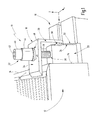
- Fig. 1 shows a perspective view of a first end clamp system 10 in a clamped state.
- a PV module 12 is clamped on its outer frame 14 on a support section 16.
- the support profile 16 may be an (extruded) rail which extends substantially in the longitudinal direction X.
- a transverse direction is designated Y.
- the vertical is labeled Z.
- the system 10 has a, preferably L-shaped, clamping bracket 18, a base member 20 and a clamping bolt 22, which is preferably realized as a threaded bolt and engages in the base member 20.
- the clamping angle 18 has a holding leg 24 for resting on the PV module 12 and a clamping leg 26 for coupling the clamping bracket 18 to the base member 20.
- the holding leg 24 is in the clamped state on an upper side 28 of the PV module 12 and the frame 14 on a flat surface.
- the connection of the retaining leg 24 with the base member 20, which engages positively in the support section 16, as will be explained in more detail below, via a toothing 30 which at a free end of the clamping leg 26 on a PV module 12 side facing is arranged.
- the toothing 30 of the clamping leg 26 interacts with a preferably step-shaped recess 32 on a module-facing side 68 (FIG. Fig. 2C ) of the base member 20.
- the recess 32 is here shaped so that it interacts positively with the toothing 30.
- the recess 32 here has a multiplicity of steps 34 arranged vertically one above the other.
- the clamping bolt 22 In order to press the clamping angle 18 vertically downward in the negative Z direction onto the PV module 12, the clamping bolt 22 is tightened.
- the clamping bolt 22 engages with its (threaded) shaft 38 in a (threaded) opening 36 in the base member 20.
- the head 40 of the clamping bolt 22 has a receptacle 42, such as a hex key receptacle, to the threaded shaft 38 further into the Turn in opening 36.
- the head 40 is freely accessible.
- a sleeve 44th be provided, which can press a washer 46 on an upper side of the retaining leg 24.
- the top of the retaining leg 24 has a in the Fig. 1 not shown opening 48, for example in the form of a slot 49 (FIG. Fig.
- the clamping bolt 22 engages through the opening 48 in the base member 20.
- the clamping bolt (head) outgoing clamping force can be evenly distributed to the support leg 24.
- the sleeve 44 can also be used to receive a spring device, not shown here, which will be described below with reference to the Fig. 2 will be described in more detail.
- the base element 20 is preferably flush with its module-facing side 70 on the frame 14 of the PV module 12.
- the clamping bracket 18 can be moved relative to the base member 20 both in the longitudinal direction X and in the vertical Z, in particular to perform height adjustments. Nevertheless, the clamping angle 18 and the base member 20 form a captive unit, ie, the components form a permanent bond, which is made possible by the support of the clamping bolt 22 in the opening 36.
- the clamping angle 18 with its toothing 30 on the clamping leg 26 can be brought into a desired height relative to the base element 20, so that the holding leg 24 rests on the upper side 28.
- the toothing 30, which is implemented here in the form of exemplarily three toothed racks extending in the Y-direction, engages in correspondingly formed steps 34. If the PV module 12 of the Fig. 1 flatter, so would the gearing 30 in the Fig. 1 engage in deeper levels 34 of the recess 32 in the base member 20.
- the clamping bracket 18 is pre-assembled, ie the module height is approximately preset, the clamping bolt 22 can be tightened to securely fix the PV module 12 on the support section 16. This will be described in more detail below.
- FIGS. 2A-2C show the end clamp system 10 of Fig. 1 in a pre-assembly state. This means that the system 10 is not yet braced on the support section 16 for the purpose of fixing a PV module 12.
- Fig. 2A shows a perspective view of the system 10th
- Fig. 2B shows a front view of the system 10 when looking in the longitudinal direction X on the system 10.
- Fig. 2C shows a side view when looking along the Y direction on the system 10.
- the system 10 will be described with reference to FIGS Figures 2A-2C to be discribed.
- the Klemmwinkei 18 may be pre-assembled in a lowest position.
- the lowest position of the holding leg 24 is preferably on the base member 20.
- the toothing 30 of the clamping leg 26 engages in the lowest three stages 34 of the recess 32 in the base member 20 a. It is understood that the length of the retaining leg 24 in the X direction and the height of the clamping leg 26 in the Z direction can be varied. The height of the clamping leg 26 can also be selected so that the holding leg 24 does not rest in the free state on the base member 20, but has a distance from the top of the base member 20.
- the already mentioned above spring device is in the Fig. 2 shown in the form of a coil spring 50 which is slid over the shaft 38 of the clamping bolt 22 and is supported either on the head 40 of the clamping bolt 22 or on a cover of the sleeve 44.
- An opposite end of the coil spring 50 is supported on the washer 46, if any. If the washer 46 is not present, the coil spring 50 is supported directly on the top of the retaining leg 24.
- the diameter of the coil spring 50 is selected so that the coil spring does not fit through the opening 48 in the retaining leg 24.
- the sleeve 44 is dimensioned so that it can be plugged onto the shaft 38 of the clamping bolt 22 and bears against the head 40 of the clamping bolt 22.
- the sleeve 44 serves to accommodate the (compressed) coil spring 50 in the clamped state of the system 10, as shown by way of example in the Fig. 1 is shown.
- the sleeve 44 further serves a more uniform application of force from the head 40 in the holding leg 24 during a Verspannvorgangs, since the sleeve 44 is usually a larger diameter than the head 40 and thus the ratio of force above the slot and on the holding leg is better.
- the base member 20 has in the side view of Fig. 2C a substantially rectangular cross section.
- the base member 20 may have a trapezoidal cross section.
- a rectangular cross section would also be conceivable.
- the recess 32 with the steps 34 is in the module facing away side 68 (see. Fig. 2C ) of the base member 20 is provided.
- the module facing away from side 68 is opposite to a module-facing side 70 of the base member 20.
- the sides 68 and 70 are oriented parallel to one another and, in the clamped state, are preferably perpendicular to the top side of the supporting profile 16 or parallel to the edge of the PV module 12.
- the module-facing side 70 preferably closes flat against the edge of the PV module 12 in the clamped state at.
- a threaded post 52 may be provided in the interior of the base element 20, which is fixed by arms explained in more detail below.
- Fig. 2B is one compared to Fig. 1 modified support section 16 'shown with a closed top.
- the base element 20 is preferably laterally, ie substantially parallel to the Y direction, plugged by rotation about a peripheral edge of the support section 16 on the support section 16 and 16 '.
- the base member 20 is flexible and has in a region which comes into contact with the support section 16, for example, a tongue and groove connection, as exemplified in the Fig. 2B is indicated. It is understood that due to the possibility that the base member 20 is laterally attached to the support section 16, a certain play in the Z direction in the region of the tongue and groove connection is required. This game fundamentally justifies the risk that the base element is tilted when the system 10 is braced ( Fig.
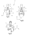
- the Fig. 3A shows a perspective view.
- the Fig. 3B shows a plan view.
- Fig. 3C shows a side view along the Y-direction.
- the retaining leg 24 and the clamping leg 26 preferably include a right angle with each other (see. Fig. 3C ).
- the length of the legs 24 and 26 can be varied as desired.
- the toothing 30 On a module-facing side 82 of the clamping leg 26, the toothing 30 is provided.
- the toothing 30 has one or more toothed racks, which in the e.g. have a triangular cross section.
- the toothed strips extend over an entire width (parallel to the Y-direction) of the clamping leg 26 in order to securely engage in the steps 34 of the base element 20, regardless of a height to be set.
- the horizontal distance between two adjacent steps 34 is height dependent.
- the opening 48 which is preferably formed as a slot 49, is located in the holding leg 24.
- the holding leg 24 is tapered at its free end. This feature is optional.
- the slot 49 is preferably arranged centrally in the width of the clamping bracket 18.
- the slot 49 extends parallel to the longitudinal direction X of the support profile 16.
- the slot 49 should extend perpendicular to the longitudinal extent of the side wall of the PV module 12 in order to move the clamping bracket 18 when setting a desired module height of the PV module 12 so that the Gearing 30 is disengaged from the stepped recess 32 comes.
- the orientation of the slot 49 is in Fig. 3C indicated in the form of an extension 83 which extends parallel to the X direction.
- FIGS. 1 and 2 show different views of the in the FIGS. 1 and 2
- the base member 20 will be described in more detail below with common reference to all views of Figures 4A-4D to be discribed.
- Fig. 4A shows a perspective view.
- Fig. 4B shows a front view.
- Fig. 4C shows a plan view and
- Fig. 4D shows a side view.
- FIG. 4B In the front view of the Fig. 4B the optional trapezoidal shape (cross section) of the base member 20 is clearly visible.
- the Indian Fig. 2B Threaded collar 52 already shown can be placed in a groove 54 which is defined by two lateral support arms 56, which leave a gap between them to pass the clamping bolt 22.
- the support arms 56 project horizontally out of the obliquely arranged trapezoid legs 58-1 and 58-2.
- feet 60-1 and 60-2 are provided on the inside for supporting the trapezoidal legs 58 at the top of the support section 16.
- barb-shaped portions 62 may be provided at the free ends of the trapezoidal leg 58.
- the barb-shaped configuration of sections 62 is merely optional.
- the trapezoidal legs 58 are connected to each other via a horizontally oriented connecting leg 64.
- the opening 36 In an upper side 64 'of the connecting leg 64, the opening 36 (see. Fig. 1 ) intended.
- the opening 36 is formed here without thread, since in the illustrated embodiment of the base member 20, a threaded rod 52 is used, which has the thread for the clamping bolt 22.
- the step-shaped recess 32 is in the side view of Fig. 4D clearly visible.
- the top view of Fig. 4C shows that each of the trapezoidal legs 58-1 and 58-2 has an equal number of equidistant steps 34 which are paired opposite each other at the same height to engage the toothing 30 of the clamping leg 26.
- the variable relative distance between the steps 34 at the same height (in the Z direction) can be clearly seen.
- the steps 34 are formed by way of example in the form of a sawtooth profile.
- the teeth have an angle of eg 45 ° (cf. Fig. 4D ).
- the horizontal surface of a step 34 serves to initiate the vertical component of force during clamping of the system 10.
- the inclined surface of the step 34 simplifies the insertion of the teeth 30 in the stepped recess 32. It is understood that the angle of the steps 34 can be variably selected . In order to prevent too easy slipping of the toothing 30 out of the stepped recess 32 in the unstressed state of the system 10, the in the Fig. 4D horizontally represented part of the step 34 are also slightly inclined, so that the angle of 45 ° is slightly sharper, for example, includes only 40 °. The (lower) part of the step 34 would then be inclined with respect to the horizontal, for example, at 5 °.
- FIGS. 5A-5C show a second embodiment of the system 10 of Fig. 1 , Fig. 5A shows a perspective view. Fig. 5B shows a front view and Fig. 5C shows a side view of the system 10th
- the clamping leg 26 In the system 10 of the Fig. 5 the clamping leg 26 'on each of its sides 80 and 82, a toothing 30 on.
- the stepped recess 32 is formed to orient along an imaginary line 96 that defines an acute angle with the module-facing side 68 of the base member 20.
- the steps 34 of the recess 32 are rectangular, so that a first portion of each step is horizontal and a second section is vertically oriented. Of course, they may also slightly inclined relative to the horizontal and vertical sections, for example, 5-10%, wherein the clamping leg 26 is adjusted accordingly.
- the steps 34 are matched to the geometry of the free end of the clamping leg 26.
- the clamping leg 26 has an underside 90 which fits in a form-fitting manner in the steps 34. The underside 90 sits in the clamped state positively in one of the stages 34th
- the system 10 of Fig. 5 shows further modifications to the Fig. 2 on.
- the washer 46 is disposed between the head 40 and the coil spring 50 here.
- the coil spring 50 is supported at its opposite end on the holding leg 24.
- the sleeve 44 ' is firmly formed on the holding leg 24 and no longer designed as a loose movable sleeve 44, as exemplified in the Figures 2A-2C was shown.
- the sleeves 44 and 44 'as well as the spring means may be eliminated without limiting the functionality of the system 10.
- the sleeve 44 and 44 'in combination with the coil spring 50 is only for ease of assembly on site.
- the coil spring 50 causes the clamping bracket 18 is biased during a height adjustment in the direction of the stepped recess 32, so that the fitter can easily release the retaining leg 24 after a successful adjustment of height, then to clamp the system 10 with free hands.
- the system 10 is pre-assembled. This means that the system 10 first in a state according to Figures 2 and 5 located.
- the clamping bracket 18 is captively connected via the clamping bolt 22 to the base member 20.
- the clamping angle 18 is preferably arranged in the lowest position.
- the clamping bracket 18 is held biased by the spring 50 there.
- the right trapezoidal leg 58-2 is pressed downwards under a deformation of the base element 20, so that the section 62 of the right trapezoidal leg 58-2 inverts around the projecting free edge of the supporting profile 16.
- the flexibility required for this is inherent to the base element 20.
- the connecting leg 64 is designed so flexible that the trapezoidal leg 58-2 can be moved beyond the edge of the support section 16. Then snaps the section 62 back and you get the in the Fig. 2B exemplified situation.
- the relative height can now be determined as a function of the height of the side surface 71 (cf. Fig. 1 ) of the frame 14.
- the clamping bolt 22 is not braced in this state and allows a movement of the clamping bracket 18 against the spring 50.
- the clamping angle 18 can be moved either first horizontally and then subsequently vertically, or the clamping bracket 18 can be directly pulled obliquely out of the steps 34.
- the system 10 is then attached to the side surface 71 (FIG. Fig. 1 ) is pushed in the longitudinal direction X of the support section 16.
- the displacement is possible because between the jaw-shaped portions 62 of the trapezoidal leg 58 and the superior edge of the support section 16 a certain play in the height direction Z is present.
- the base element 20 can, of course, be attached directly to the desired position on the frame 14 of the PV module 12.
- the system 10 is braced by the clamping bolt 22 is moved in the direction of the base member 20.
- pressure is exerted on the retaining leg 24 and the clamping leg 26.
- the pressure on the retaining leg 24 causes the PV module 12 is clamped to the support profile 16.
- the pressure on the clamping leg 26 causes the base member is not tilted due to the toothing 30 and the bottom 90 relative to the horizontal, which is defined by the top of the support section 16.
- the individual components 18-22 of the system 10 can also be connected to one another at the construction site.
- the base member 20, the clamping bolt 22 and the clamping bracket 18 are then not pre-assembled.
- the assembly of these three components is time consuming and should therefore not be done on site.
- a first step S10 the base member 20 is laterally attached to the support section 16.
- a step S12 the clamping angle is moved relative to the base member 20 for height adjustment.
- the clamping angle is braced via the clamping bolt with the base element.
Applications Claiming Priority (1)
| Application Number | Priority Date | Filing Date | Title |
|---|---|---|---|
| DE102011118560A DE102011118560A1 (de) | 2011-11-10 | 2011-11-10 | Endklemmen für gerahmte Photovoltaikmodule |
Publications (2)
| Publication Number | Publication Date |
|---|---|
| EP2592365A2 true EP2592365A2 (fr) | 2013-05-15 |
| EP2592365A3 EP2592365A3 (fr) | 2014-07-02 |
Family
ID=47143754
Family Applications (1)
| Application Number | Title | Priority Date | Filing Date |
|---|---|---|---|
| EP12192032.6A Withdrawn EP2592365A3 (fr) | 2011-11-10 | 2012-11-09 | Pinces d'extrémité pour modules photovoltaïques encadrés |
Country Status (2)
| Country | Link |
|---|---|
| EP (1) | EP2592365A3 (fr) |
| DE (1) | DE102011118560A1 (fr) |
Cited By (18)
| Publication number | Priority date | Publication date | Assignee | Title |
|---|---|---|---|---|
| JP2015034388A (ja) * | 2013-08-08 | 2015-02-19 | 元旦ビューティ工業株式会社 | パネルの取付部材及び取付構造 |
| US9673583B2 (en) | 2015-08-28 | 2017-06-06 | Solarcity Corporation | Photovoltaic mounting rail connector with drop-down connection to first photovoltaic module and slide-in connection to second photovoltaic module |
| JP2017223109A (ja) * | 2017-08-10 | 2017-12-21 | 元旦ビューティ工業株式会社 | パネルの取付部材及び取付構造 |
| US9876462B2 (en) | 2015-08-27 | 2018-01-23 | Solarcity Corporation | Support system for photovoltaic mounting rail having cylindrical base that rotates into a locked position |
| US9874021B2 (en) | 2015-08-28 | 2018-01-23 | Solarcity Corporation | Tile and slate roof flashing systems |
| EP3364124A1 (fr) * | 2017-02-08 | 2018-08-22 | Esdec B.V. | Dispositif et procédé de fixation de panneau solaire sur un rail de support pour panneaux solaires |
| GB2529687B (en) * | 2014-08-29 | 2018-12-19 | Milenco Ltd | Improved gripper pad for towing mirror clamp |
| CN110101230A (zh) * | 2019-04-22 | 2019-08-09 | 浙江大学 | 一种可调高度支撑脚 |
| US10680417B2 (en) | 2015-07-23 | 2020-06-09 | Rittal Gmbh & Co. Kg | Securing system for securing a roof structure in a notch on the roof of a switch cabinet |
| WO2020187472A1 (fr) * | 2019-09-05 | 2020-09-24 | Aerocompact Gmbh | Borne d'extrémité pour fixer un module photovoltaïque doté d'un cadre |
| US11056998B2 (en) * | 2017-05-01 | 2021-07-06 | Hubbell Incorporated | Universal bonding end clamp |
| US11070166B2 (en) | 2018-04-19 | 2021-07-20 | Energy Consultants Group, LLC | Adjustable mounting device |
| US11261893B2 (en) * | 2017-08-15 | 2022-03-01 | National Nail Corp. | Hidden fastener unit and related method of use |
| USD945870S1 (en) | 2020-11-17 | 2022-03-15 | National Nail Corp. | Fastener positioning device |
| US11296648B1 (en) | 2021-05-14 | 2022-04-05 | Sunmodo Corporation | Solar panel racking system and devices for the same |
| US11603670B2 (en) | 2017-08-15 | 2023-03-14 | National Nail Corp. | Hidden fastener unit and related method of use |
| US11757398B2 (en) * | 2015-03-11 | 2023-09-12 | Unirac Inc. | Universal sloped roof solar panel mounting system |
| USD1022684S1 (en) | 2023-02-23 | 2024-04-16 | National Nail Corp. | Fastener positioning device |
Families Citing this family (2)
| Publication number | Priority date | Publication date | Assignee | Title |
|---|---|---|---|---|
| CN104022722B (zh) * | 2014-05-19 | 2016-03-30 | 苏州爱康金属科技有限公司 | 直立锁边彩钢瓦屋面光伏支架结构 |
| US10240820B2 (en) * | 2015-03-25 | 2019-03-26 | Ironridge, Inc. | Clamp for securing and electrically bonding solar panels to a rail support |
Citations (6)
| Publication number | Priority date | Publication date | Assignee | Title |
|---|---|---|---|---|
| DE202004015815U1 (de) | 2004-10-09 | 2004-12-30 | Veloflex Carsten Thormählen (GmbH & Co.) | Aufbewahrungsmappe |
| DE202006013261U1 (de) | 2006-08-24 | 2006-11-30 | Sbu Photovoltaik Gmbh | Befestigung für Solarmodule |
| DE102006000089A1 (de) | 2006-02-23 | 2007-08-30 | Hilti Ag | Befestigungsvorrichtung für die Befestigung von Solarpaneelen an einer Montageschiene |
| DE202009010487U1 (de) | 2009-08-03 | 2009-12-10 | Schletter Gmbh | Endklemme zur Befestigung gerahmter PV-Module |
| EP2132495B1 (fr) | 2007-03-30 | 2010-12-29 | Haticon GmbH | Dispositif de fixation pour modules solaires |
| DE202011001761U1 (de) | 2011-01-20 | 2011-04-21 | Vm Edelstahltechnik Gmbh | Klemmvorrichtung |
Family Cites Families (6)
| Publication number | Priority date | Publication date | Assignee | Title |
|---|---|---|---|---|
| DE10145393C1 (de) * | 2001-09-14 | 2003-05-22 | Manet Glas Systeme Gmbh Thaur | Befestigungsvorrichtung von Solarmodulen |
| DE202004015811U1 (de) * | 2004-10-13 | 2004-12-16 | Bbt Thermotechnik Gmbh | Befestigungsvorrichtung für mindestens einen Sonnenkollektor |
| NL2001380C2 (nl) * | 2008-03-17 | 2009-09-21 | Ubbink Bv | Hellend dak met zonnepaneelhouder. |
| FR2950375A1 (fr) * | 2009-09-21 | 2011-03-25 | Atrya | Systeme de toiture integrant des panneaux solaires |
| DE202010000121U1 (de) * | 2010-02-04 | 2010-06-10 | Alcom International Gmbh | Klemmprofil |
| ES1071742Y (es) * | 2010-02-10 | 2010-06-25 | Producciones Mitjavila Sa | Estructura de fijacion de paneles solares |
-
2011
- 2011-11-10 DE DE102011118560A patent/DE102011118560A1/de not_active Withdrawn
-
2012
- 2012-11-09 EP EP12192032.6A patent/EP2592365A3/fr not_active Withdrawn
Patent Citations (6)
| Publication number | Priority date | Publication date | Assignee | Title |
|---|---|---|---|---|
| DE202004015815U1 (de) | 2004-10-09 | 2004-12-30 | Veloflex Carsten Thormählen (GmbH & Co.) | Aufbewahrungsmappe |
| DE102006000089A1 (de) | 2006-02-23 | 2007-08-30 | Hilti Ag | Befestigungsvorrichtung für die Befestigung von Solarpaneelen an einer Montageschiene |
| DE202006013261U1 (de) | 2006-08-24 | 2006-11-30 | Sbu Photovoltaik Gmbh | Befestigung für Solarmodule |
| EP2132495B1 (fr) | 2007-03-30 | 2010-12-29 | Haticon GmbH | Dispositif de fixation pour modules solaires |
| DE202009010487U1 (de) | 2009-08-03 | 2009-12-10 | Schletter Gmbh | Endklemme zur Befestigung gerahmter PV-Module |
| DE202011001761U1 (de) | 2011-01-20 | 2011-04-21 | Vm Edelstahltechnik Gmbh | Klemmvorrichtung |
Cited By (25)
| Publication number | Priority date | Publication date | Assignee | Title |
|---|---|---|---|---|
| JP2015034388A (ja) * | 2013-08-08 | 2015-02-19 | 元旦ビューティ工業株式会社 | パネルの取付部材及び取付構造 |
| GB2529687B (en) * | 2014-08-29 | 2018-12-19 | Milenco Ltd | Improved gripper pad for towing mirror clamp |
| US11757398B2 (en) * | 2015-03-11 | 2023-09-12 | Unirac Inc. | Universal sloped roof solar panel mounting system |
| US10680417B2 (en) | 2015-07-23 | 2020-06-09 | Rittal Gmbh & Co. Kg | Securing system for securing a roof structure in a notch on the roof of a switch cabinet |
| US9876462B2 (en) | 2015-08-27 | 2018-01-23 | Solarcity Corporation | Support system for photovoltaic mounting rail having cylindrical base that rotates into a locked position |
| US9874021B2 (en) | 2015-08-28 | 2018-01-23 | Solarcity Corporation | Tile and slate roof flashing systems |
| US9673583B2 (en) | 2015-08-28 | 2017-06-06 | Solarcity Corporation | Photovoltaic mounting rail connector with drop-down connection to first photovoltaic module and slide-in connection to second photovoltaic module |
| NL2018346B1 (nl) * | 2017-02-08 | 2018-09-03 | Esdec B V | Inrichting en werkwijze voor het fixeren van zonnepanelen op een draagrail voor zonnepanelen |
| EP3364124A1 (fr) * | 2017-02-08 | 2018-08-22 | Esdec B.V. | Dispositif et procédé de fixation de panneau solaire sur un rail de support pour panneaux solaires |
| US11056998B2 (en) * | 2017-05-01 | 2021-07-06 | Hubbell Incorporated | Universal bonding end clamp |
| JP2017223109A (ja) * | 2017-08-10 | 2017-12-21 | 元旦ビューティ工業株式会社 | パネルの取付部材及び取付構造 |
| US11603670B2 (en) | 2017-08-15 | 2023-03-14 | National Nail Corp. | Hidden fastener unit and related method of use |
| US11920618B2 (en) | 2017-08-15 | 2024-03-05 | National Nail Corp. | Hidden fastener unit and related method of use |
| US11261893B2 (en) * | 2017-08-15 | 2022-03-01 | National Nail Corp. | Hidden fastener unit and related method of use |
| US11070166B2 (en) | 2018-04-19 | 2021-07-20 | Energy Consultants Group, LLC | Adjustable mounting device |
| CN110101230A (zh) * | 2019-04-22 | 2019-08-09 | 浙江大学 | 一种可调高度支撑脚 |
| CN110101230B (zh) * | 2019-04-22 | 2021-01-08 | 浙江大学 | 一种可调高度支撑脚 |
| WO2021043407A1 (fr) * | 2019-09-05 | 2021-03-11 | Aerocompact Gmbh | Dispositif de serrage terminal pour fixer un module photovoltaïque muni d'un cadre |
| WO2020187472A1 (fr) * | 2019-09-05 | 2020-09-24 | Aerocompact Gmbh | Borne d'extrémité pour fixer un module photovoltaïque doté d'un cadre |
| USD945870S1 (en) | 2020-11-17 | 2022-03-15 | National Nail Corp. | Fastener positioning device |
| US11552591B2 (en) | 2021-05-14 | 2023-01-10 | Sunmodo Corporation | Solar panel racking system and devices for the same |
| US11296648B1 (en) | 2021-05-14 | 2022-04-05 | Sunmodo Corporation | Solar panel racking system and devices for the same |
| US11621665B2 (en) | 2021-05-14 | 2023-04-04 | Sunmode Corporation | Solar panel racking system and devices for the same |
| US11784607B2 (en) | 2021-05-14 | 2023-10-10 | Sunmodo Corporation | Solar panel racking system and devices for the same |
| USD1022684S1 (en) | 2023-02-23 | 2024-04-16 | National Nail Corp. | Fastener positioning device |
Also Published As
| Publication number | Publication date |
|---|---|
| EP2592365A3 (fr) | 2014-07-02 |
| DE102011118560A1 (de) | 2013-05-16 |
Similar Documents
| Publication | Publication Date | Title |
|---|---|---|
| EP2592365A2 (fr) | Pinces d'extrémité pour modules photovoltaïques encadrés | |
| DE202011107843U1 (de) | Endklemmen für gerahmte Photovoltaikmodule | |
| EP1899552B1 (fr) | Systeme de coffrage de plafond | |
| EP1647782A2 (fr) | Dispositif de support d'au moins un collecteur solaire | |
| AT412909B (de) | Einrichtung zur befestigung von solarmodulen an befestigungsprofilen | |
| EP0212228B1 (fr) | Dispositif pour l'ancrage de plaques | |
| WO2012116777A2 (fr) | Élément de fixation pour cadre de module solaire | |
| EP2093524A1 (fr) | Dispositif destiné au montage de modules solaires | |
| EP2498023A1 (fr) | Système de fixation standardisé pour modules photovoltaïques et procédé de montage | |
| LU85715A1 (de) | Kraftschluessig-elastische schienenbefestigung fuer gleisanlagen | |
| AT10883U1 (de) | Befestigungsvorrichtung mit einer klemmvorrichtung | |
| EP2636970A1 (fr) | Système de fixation | |
| EP2378221A2 (fr) | Système de montage pour modules solaires et procédé de montage d'une installation solaire | |
| DE202007012830U1 (de) | Varioträger | |
| DE102012004773A1 (de) | Vorrichtung für die Halterung von Photovoltaikmodulen auf Freiflächen | |
| DE10262175B4 (de) | Antennenhalter | |
| CH704215A2 (de) | Sanitärwannenträger, insbesondere Duschwannenträger. | |
| DE19907781A1 (de) | Formvorrichtung zur Herstellung vorgespannter Stahlbeton-Deckenplatten | |
| DE3038019C2 (de) | Rasterdecke | |
| EP3599335B1 (fr) | Joint d'étanchéité abaissable, en particulier pour portes coulissantes | |
| DE3003867A1 (de) | Kraftschluessige und elastisch nachgiebige schienenbefestigung fuer gleisanlagen | |
| DE102018203080B4 (de) | Fundamentsystem für die lagerung von flächig nebeneinander angeordneten solarpaneelen | |
| EP3071896A1 (fr) | Dispositif de retenue pour boîtier et procédé de montage du boîtier à l'aide du dispositif de retenue | |
| EP3486400A1 (fr) | Sous-construction pour un revêtement de façade et procédé de montage d'une sous-construction | |
| DE19931040C2 (de) | Verkleidungssystem für eine Wanne, vorzugsweise Badewanne |
Legal Events
| Date | Code | Title | Description |
|---|---|---|---|
| PUAI | Public reference made under article 153(3) epc to a published international application that has entered the european phase |
Free format text: ORIGINAL CODE: 0009012 |
|
| AK | Designated contracting states |
Kind code of ref document: A2 Designated state(s): AL AT BE BG CH CY CZ DE DK EE ES FI FR GB GR HR HU IE IS IT LI LT LU LV MC MK MT NL NO PL PT RO RS SE SI SK SM TR |
|
| AX | Request for extension of the european patent |
Extension state: BA ME |
|
| PUAL | Search report despatched |
Free format text: ORIGINAL CODE: 0009013 |
|
| AK | Designated contracting states |
Kind code of ref document: A3 Designated state(s): AL AT BE BG CH CY CZ DE DK EE ES FI FR GB GR HR HU IE IS IT LI LT LU LV MC MK MT NL NO PL PT RO RS SE SI SK SM TR |
|
| AX | Request for extension of the european patent |
Extension state: BA ME |
|
| RIC1 | Information provided on ipc code assigned before grant |
Ipc: F24J 2/52 20060101AFI20140528BHEP Ipc: H01L 31/042 20140101ALI20140528BHEP |
|
| 17P | Request for examination filed |
Effective date: 20141203 |
|
| RBV | Designated contracting states (corrected) |
Designated state(s): AL AT BE BG CH CY CZ DE DK EE ES FI FR GB GR HR HU IE IS IT LI LT LU LV MC MK MT NL NO PL PT RO RS SE SI SK SM TR |
|
| STAA | Information on the status of an ep patent application or granted ep patent |
Free format text: STATUS: THE APPLICATION IS DEEMED TO BE WITHDRAWN |
|
| 18D | Application deemed to be withdrawn |
Effective date: 20160601 |