EP2581542B2 - Haustür-türblatt sowie Herstellverfahren hierfür - Google Patents
Haustür-türblatt sowie Herstellverfahren hierfür Download PDFInfo
- Publication number
- EP2581542B2 EP2581542B2 EP12185541.5A EP12185541A EP2581542B2 EP 2581542 B2 EP2581542 B2 EP 2581542B2 EP 12185541 A EP12185541 A EP 12185541A EP 2581542 B2 EP2581542 B2 EP 2581542B2
- Authority
- EP
- European Patent Office
- Prior art keywords
- door leaf
- frame
- shell
- door
- profile
- Prior art date
- Legal status (The legal status is an assumption and is not a legal conclusion. Google has not performed a legal analysis and makes no representation as to the accuracy of the status listed.)
- Active
Links
Images


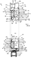

Classifications
-
- E—FIXED CONSTRUCTIONS
- E06—DOORS, WINDOWS, SHUTTERS, OR ROLLER BLINDS IN GENERAL; LADDERS
- E06B—FIXED OR MOVABLE CLOSURES FOR OPENINGS IN BUILDINGS, VEHICLES, FENCES OR LIKE ENCLOSURES IN GENERAL, e.g. DOORS, WINDOWS, BLINDS, GATES
- E06B3/00—Window sashes, door leaves, or like elements for closing wall or like openings; Layout of fixed or moving closures, e.g. windows in wall or like openings; Features of rigidly-mounted outer frames relating to the mounting of wing frames
- E06B3/70—Door leaves
- E06B3/82—Flush doors, i.e. with completely flat surface
- E06B3/822—Flush doors, i.e. with completely flat surface with an internal foursided frame
-
- E—FIXED CONSTRUCTIONS
- E06—DOORS, WINDOWS, SHUTTERS, OR ROLLER BLINDS IN GENERAL; LADDERS
- E06B—FIXED OR MOVABLE CLOSURES FOR OPENINGS IN BUILDINGS, VEHICLES, FENCES OR LIKE ENCLOSURES IN GENERAL, e.g. DOORS, WINDOWS, BLINDS, GATES
- E06B3/00—Window sashes, door leaves, or like elements for closing wall or like openings; Layout of fixed or moving closures, e.g. windows in wall or like openings; Features of rigidly-mounted outer frames relating to the mounting of wing frames
- E06B3/70—Door leaves
- E06B2003/7059—Specific frame characteristics
- E06B2003/7074—Metal frames
- E06B2003/7076—Metal frames insulated
-
- E—FIXED CONSTRUCTIONS
- E06—DOORS, WINDOWS, SHUTTERS, OR ROLLER BLINDS IN GENERAL; LADDERS
- E06B—FIXED OR MOVABLE CLOSURES FOR OPENINGS IN BUILDINGS, VEHICLES, FENCES OR LIKE ENCLOSURES IN GENERAL, e.g. DOORS, WINDOWS, BLINDS, GATES
- E06B3/00—Window sashes, door leaves, or like elements for closing wall or like openings; Layout of fixed or moving closures, e.g. windows in wall or like openings; Features of rigidly-mounted outer frames relating to the mounting of wing frames
- E06B3/70—Door leaves
- E06B2003/7059—Specific frame characteristics
- E06B2003/7082—Plastic frames
Definitions
- the invention relates to a door leaf for a house door, a house door provided with such a door leaf, and a manufacturing method for such a door leaf.
- Front doors are doors that can be used as the outer closure of a building.
- the invention relates in particular to front doors to be used as the main entrance of residential buildings, in particular single-family houses, apartment buildings, terraced houses, semi-detached houses.
- Such front doors must primarily fulfill the two functions of burglary protection and thermal insulation.
- front doors As materials for front doors, there are mainly front doors made of wood, plastic or metal on the market. Although wood and plastic have lower thermal conductivity compared to metal materials, so that thermal protection seems to be easier to achieve in principle, on the other hand wood and plastic are usually less resistant than metals, so that front doors based on metal materials are usually more robust, warp less even with frequent and longer use and provide a good basis for increased burglary protection. Front doors based on metal materials have a high quality impression and can be manufactured very precisely with small gap dimensions and can also be operated over a longer period of time. Because of this, the front doors can be designed to close more tightly and a high level of burglary protection can be achieved.
- the invention therefore applies exclusively to front doors based on metal materials.
- the EP 1 568 842 A2 explains the construction principles currently used for such metal front doors.
- Front doors have a door leaf, also referred to as a door leaf, and a door frame, also referred to as a frame.
- the door frame can have a glazed side part, for example.
- the door leaf usually has a door leaf frame and a door panel.
- door panels In the previous production of house doors available on the market, it has been standard for house door manufacturers to build the door leaf frame based on metal profiles and to provide it with locking technology - door hinges, locks, etc. - with door panels usually being supplied by door panel manufacturers.
- the door panel manufacturers had different front door motifs in their range, which were developed by designers.
- the door panels have usually been constructed as sandwich panels, with a motif panel to be arranged on the outside carrying the motif, with an inner panel to be arranged on the inside and insulation between the two panels also being present. Depending on the motif selected, such door panels designed as sandwich panels are also provided with glazing cut-outs with glazing.
- EP 1 568 842 A2 shows different production methods for known wing-covering configurations.
- the insulation and the inner panel of the door panel designed as a sandwich panel are cut out, while the motif panel is left essentially as large as the outer broad side of the door leaf, so that only the motif panel rests on the outside of the door leaf frame.
- the EP 1 568 842 A2 therefore proposes a wing-covering design, where the door panel designed as a sandwich panel rests with all its components on the outside of the door leaf frame. This allows the door panel to be processed more easily because it is cut to size as a whole.
- the door leaf frame can be designed more simply, since the insulation of the door panel can take over the thermal insulation function of the connecting webs, so that the door leaf frame only needs to be made of a simple metal profile without connecting webs.
- the invention further relates to a house door provided with such a house door leaf and to a method for producing such a house door leaf.
- the invention creates a house door leaf with a door leaf frame and the panels forming the broad sides of the door leaf and with insulation between the panels, the door leaf frame being formed from a metal half-shell and a plastic half-shell.
- a first of the panels lies on the metal half-shell, covering it to a large extent
- the second panel lies on the plastic half-shell, covering it to a large extent
- the door leaf frame is composed of frame members, the frame members each consisting of two frame member half-shells, of which a first frame member half-shell is designed as a metal profile and a second frame member half-shell is designed as a plastic profile.
- the two half-shells are formed from hollow profiles.
- the hollow sections are tubular sections.
- the hollow profiles of the plastic half-shell are designed essentially in the shape of a U-profile with two U-legs and a U-web connecting the U-legs, with stiffening webs being formed between the U-legs and/or between each U-leg and the U-web.
- the second panel is glued directly to the plastic half-shell.
- the panels lie over their entire surface on the wide-side end face of the associated half-shells, with one end edge of the panel terminating essentially flush with an outer edge delimiting the end face.
- the insulation is formed by foaming the door leaf cavity formed between the door leaf frame and the panels that rest on it.
- each of the two half-shells has at least one hook formation that engages in the door leaf cavity and is surrounded by foam through the insulation.
- the metal half-shell is thicker than the plastic half-shell in the thickness direction of the door leaf.
- At least one of the panels is preferably made of metal.
- the panels are formed from sheet metal.
- the panel to be arranged on the outside is preferably designed as a wing-covering aluminum sheet.
- the door leaf frame By constructing the door leaf frame from two half-shells, with one half-shell made of metal and the other half-shell made of plastic materials, a high-quality, rigid door leaf frame can be formed on the one hand, which provides a basis for good burglary protection, in particular due to the metal half-shell, offers a high quality impression and on the other hand, due to the plastic half-shell, there are no connecting webs made of non-metal materials. Only two sub-elements per frame rail need to be manufactured and joined together. The bond results in high rigidity and high thermal insulation capacity.
- the door panel frame extends substantially through the full thickness of the door panel so that the full thickness of the door panel can be used to provide a rigid door panel frame.
- the construction shown results in greater rigidity, which leads to improvements in the sealing effects - improved, defined gap dimensions all around the door leaf - in terms of burglary protection - improved rigidity and higher resistance class.
- frame members that consist of two frame member half-shells.
- the door leaf frame itself is then preferably manufactured in such a way that four frame bars are cut off to the appropriate length and then connected to one another.
- the connection at the corners is preferably carried out via corner connectors engaging in the metal half-shells. Due to the fastening of the corner connectors to the metal elements of the door leaf frame, a strong and rigid connection can be achieved.
- the second half-shells of the frame rail can also be additionally reinforced with corner brackets. Plastic corner brackets are preferably used for this purpose.
- the joining of the two frame member half-shells is preferably done - as is the case in principle is already known for connecting metal profiles with plastic connecting bars - via tongue and groove connections.
- at least two tongue and groove connections are provided here between the half-shells, which are spaced apart from one another and extend along the length of the frame bars.
- the tongue and groove connections are preferably provided near the end-side boundary walls of the half-shells.
- a particularly high level of reinforcement results when both half-shells are each formed from hollow profiles, in particular tubular profiles.
- a half-shell base body is preferably provided, which is essentially U-shaped and can be designed with a thicker wall, with stiffening webs that can have a thinner wall thickness running between the U-legs one below the other or between the U-legs and a web connecting the U-legs. At least one of the stiffening webs can also have a stiffening tube profile.
- these chambers can be formed within the plastic hollow profile, which is particularly useful for stiffening and thermal insulation.
- these chambers can be foamed with an intumescent insulation material.
- not only an outer panel forming the outside of the house door leaf rests on the outside of the door leaf frame.
- a panel provided on the inside is designed as a cover panel, so that it covers at least a large part of the door leaf frame on the inside of the house door leaf.
- this means that the front door leaf also has a visually appealing design on the inside; there is no step on the inside due to the door leaf frame.
- the panel is made of sheet metal, e.g.
- Light metal sheet is formed - achieve additional stiffening due to the support of the inner panel. Due to the outside and inside support of the two panels, a large cavity is created inside the door leaf, which can be used for insulation purposes.
- the remaining cavities in the door leaf frame are preferably filled with foam.
- Cavities that remain between the door leaf frame and other inserts within the door leaf frame are preferably filled with foam.
- the half-shells are also particularly preferably filled with foam.
- the metal half-shell preferably carries functional elements of the door, such as in particular door hinges or a multi-point lock. It is further preferred that the metal half-shell is made thicker than the plastic half-shell. As a result, a larger area of the door leaf thickness is used for the more rigid metal material and more space can be created for the functional elements and their attachment. More preferably, the plastic half-shell is assigned to an outside of the door leaf, with a panel forming the outside of the door leaf resting on the plastic half-shell. The plastic half-shell is thus located between the outside and the metal half-shell with the functional elements. This improves the insulation effect, functionality and burglary protection.
- the panels preferably rest over their entire surface on the broad-side surfaces of the half-shells. The use of the entire surface of the half-shells as a support surface for the panels results in an attractive design, good fastening options and high rigidity.
- the attachment between the panels and the door leaf frame is preferably effected in a material-to-material manner, preferably by gluing.
- the broad-side contact surfaces of the half-shells, on which the panels rest, are preferably provided with at least one groove-shaped depression extending in the longitudinal direction of the frame members. More generally, the bearing surfaces are not completely flat, but are designed with indentations. By forming such indentations, the bondability and the hold of the panels on the half-shells can be improved.
- At least one of the two half-shells preferably both half-shells, is provided with a hook formation that engages in the door leaf cavity on the areas facing the door leaf cavity, then a particularly strong bond can be achieved between the foam filling and the door leaf frame when the hook formation is foamed.
- In 1 is an interior view of a front door 10 shown with a door frame 12 and a door panel 14.
- the door panel 14 is pivoted inwards on the door frame 12 by means of door hinges 16 .
- on the inside 1 shown inside is a door handle 18 and a rosette 20 is provided for the inner end of a lock cylinder of a door lock.
- FIG. 2 shows the outside view of the front door 10 from 1 .
- the door frame 12 covers the outer edges of the door leaf 14 on the outside.
- a front door handle 22 and only a rosette 24, but no door handle 18, are also provided on the outside.
- inner broad side 26 which remains visible within the door frame 12 when the front door 10 is closed, is formed entirely by an inner panel 28.
- the outer wide side 30 of the door leaf 14 shown is, insofar as it is visible within the door frame 12, formed entirely by an outer panel 32.
- the outer panel 32 is designed as a motif plate 34 and has different decorative elements 36 and designs depending on the motif selected. A large number of different motifs with different ones are conceivable here.
- the door leaf 14 has a door leaf frame 40 and the panels 28, 32 forming the door leaf broad sides 26, 30 and insulation 38 between the panels 28, 32.
- the door leaf frame 40 is formed from a metal half-shell 42 and a plastic half-shell 44 .
- the door leaf frame 40 is made up of an upper horizontal frame member 46, a lower horizontal frame member 48, a lock-side vertical frame member 50 and a hinge-side vertical frame member 52.
- Each of the frame rails 46 , 48 , 50 , 52 consists of two frame rail half-shells, with a first frame rail half-shell 54 being formed from a metal profile 56 and a second frame rail half-shell 58 being formed from a plastic profile 60 .
- the metal profile 56 is, for example, a hollow profile in the form of a tubular profile 62 made of metal, in particular light metal, such as aluminum alloys or the like.
- the plastic profile 60 is made of a suitable plastic, such as polyamide, aramid or fiber-reinforced plastic materials (CFRP, GFRP) or the like.
- the plastic profile 60 is preferably a hollow profile in the form of a tubular profile 64.
- the plastic profile 60 of the plastic half-shell 44 is preferably essentially in the form of a U-profile with two U-legs 66, 68 and a U-web 70 connecting the U-legs 66, 68.
- a transverse stiffening web 72 is provided between the legs 66, 68 of the U.
- a diagonally running diagonal stiffening web 74 is provided in the corner regions.
- the transverse stiffening web 72 has a rectangular profile 76 with stiffening ribs 78 .
- the frame beam half-shells 54, 58 have hook formations 84 protruding into the door leaf cavity 82, which is formed between the panels 28, 32 and the door leaf frame 40, on the inner side 80 facing the interior space enclosed by the door leaf frame 40.
- the plastic profile 60 has an inwardly protruding projection 86 on the inner side 80 facing the door leaf cavity 82 in the region of the transition between the inner U-leg 68 and the U-web 70 .
- the inner wall 88 of the frame member which is formed partially on the inner U-leg 68 for example, has on the plastic profile 60 a wall area 90 extending in the thickness direction and a wall area 92 extending obliquely into the interior and outwards.
- the U-web 70 is guided correspondingly obliquely in the area of the projection 86 beyond the wall area 90 extending in the direction of thickness and merges in one piece into the oblique wall area 92 in the area of the projection 86 .
- the surface 94 of the plastic profile 60 directed outwards is enlarged towards the middle of the broad sides 26, 30.
- This outward surface 94 serves as a bearing surface 96 for the outer panel 32.
- the bearing surface 96 is provided with a plurality of indentations 98.
- the depressions 98 are provided in the form of channels or beads along the longitudinal extension of the plastic profile 60 .
- three or more parallel indentation grooves are spaced side-by-side.
- the hook formation 84 acts integrally on the projection 86 .
- the hook formation 84 has a sloping area 100 extending obliquely inwards from the tip of the projection 86, which forms the edge between the inner wall 88 and the bearing surface 96, which is adjoined by an area 102 protruding inwards in the thickness direction.
- an end flange area 104 which protrudes back towards the U-shaped main body of the plastic hollow profile.
- At least two tongue-and-groove connections 106 are provided between the two frame rail half-shells 54 and engage in one another in a form-fitting manner.
- the tongue and groove connections 106 are designed with dovetail-type rear grips.
- the plastic profile 60 has thickenings 108 at the ends of wall regions extending in the thickness direction of the door leaf 14, which engage in C-profile-shaped groove edges 110 on the metal profile 56 in a form-fitting manner and secured against being pulled out.
- the thickenings 108 are provided on the free end edges of the two legs 66, 68 of the U.
- the end areas of the U-legs 66, 68 are designed to be offset and set back into the profile interior, as shown in the drawings.
- the metal profile 56 is a tubular profile 62 which is essentially rectangular with two profile walls 112, 114 extending parallel to the broad sides and two profile walls 116, 118 extending essentially in the thickness direction.
- the outer profile wall 116 which is arranged on the very inside of the door leaf 14 and extends in the thickness direction, is wider than the inner profile wall 114, which extends inside the door leaf frame 40 at the transition to the plastic profile 60 and extends parallel to the broad side direction 0 of the door leaf frame 40 and forms a stop fold 122 of the door leaf 14.
- this outer profile wall 112 which extends parallel to the broad lateral direction, projects beyond the inner wall 88 of the door leaf frame 40, so that a projection 128 is formed on the edge region between the inner wall 88 and an outwardly directed surface 126 forming a bearing surface 124, comparable to the projection 86 of the plastic profile 60 is.
- the hook formation 84 is integrally attached to this projection 128 in the same way as in the case of the plastic profile 60 embodied with a sloping area 100 , area 102 protruding inwards in the thickness direction and end flange area 104 .
- the inner profile wall 118 extending in the direction of thickness forms, together with the inner leg 68 of the U, the inner wall 88 of the door leaf frame 40.
- This inner profile wall 118 which extends in the direction of thickness, has, similar to the inner leg 68 of the U, a wall area 130 extending in the direction of thickness and an inclined wall area 132 for forming the approximately triangular projection 128.
- the inner profile wall 114 which extends parallel to the broad side direction, is essentially flat and plate-shaped in the exemplary embodiment shown here, with the C-shaped groove edges 110 being formed by two mutually facing hook-shaped projections 134 on the two edge regions near the end face 120 of the door leaf frame 40 on the one hand and near the inner wall 88 of the door leaf frame 40 on the other.
- the outer profile wall 116 extending in the direction of thickness has a C-shaped, essentially rectangular indentation-e.g. designed as a C-shaped profile recess 136-for forming a receiving groove for a seal or the like.
- the lower horizontal frame member 48 has the same profile as the other frame members 46, 50, 52. Accordingly, the lower horizontal frame bar 48 is also provided with the stop fold 122 . In this lower horizontal frame member 48, a seal 138 for sealing the lower door gap 140 is provided in the depression of the C-shaped profile recess 136, which is formed in the outer profile wall 116 extending in the thickness direction.
- the entire outwardly directed surface 126 of the outer profile wall 112 extending parallel to the broad side direction is designed as a bearing surface 124 for the inner panel 28 .
- the inner panel 28 covers the entire surface of the wing on this outwardly directed surface 126 of the outer profile wall 112 extending parallel to the direction of the broad side.
- only a few indentations 142 are provided in the bearing surface, which indentations 142 serve to improve a material connection between the panel 28 and the metal profile 56 .
- the depressions 142 are formed, for example, as channels or grooves extending along the metal profile.
- the metal half-shell 42 has a greater extent in the thickness direction of the door leaf 14 than the plastic half-shell 44.
- the first frame rail half-shell 54 extends over 55% to 80% of the thickness of the door leaf frame 40, and the rest of 65% to 20%, respectively, is occupied by the second frame rail half-shell 58.
- the structure of the door leaf 14 in the thickness direction in the area of the door leaf frame 40 of an exemplary embodiment is described in more detail below.
- an outer panel 150 which is made of aluminum or other light metal (in particular aluminum alloy), for example, followed by an outer profile 152 made of a plastic material, for example the plastic profile 60, e.g. designed as a polyamide profile (thermally insulated).
- an inner panel 154 for example made of light metal, for example aluminum alloy.
- Outer panel 150 and inner panel 154 are examples of the design of the panels 28, 32.
- the panels 28, 32 rest directly on the door leaf frame 40, so that there is at most an adhesive between the panels 28, 32 and the door leaf frame 40.
- Such a construction of the door leaf 14 is comparable in terms of quality to the door leaf construction as shown in FIG EP 1 568 842 A2 is placed under protection, but not only on the outside but also on the inside, an attractive design is achieved by a wing-covering design and, in addition, the production method in large industrial series is less complex than that in EP 1 568 842 A2 solution shown with sandwich panel on the outside.
- An advantage of this new design is that the outer profile no longer has to contain a metal-non-metal composite profile, to which an aluminum sheet must also be attached. Rather, the construction is simplified and the thermal insulation is significantly improved.
- the door frame has 12 door frame spars 160 which are each constructed from a three-part frame composite profile 162 .
- the three-part frame composite profile 162 has a metal outer shell 164, for example made of aluminum, other light metal or alloys, a metal inner shell 166, for example made of aluminum, other light metal or alloys, and as a third partial element plastic insulating bars 168 - e.g. polyamide insulating bars - for thermal separation.
- the metal inner shell 166 is provided with a stop fold 170 which projects in the direction of the door leaf 14 and against which the edge region of the outer panel 32 strikes when the front door 10 is in the closed state.
- the frame-side stop fold 170 has a C-profile-shaped receiving groove, in which an outer stop seal 172 engages.
- the door frame 12 has a lock-side vertical door frame beam 160a, an upper horizontal door frame beam 160b and a door hinge-side vertical door frame beam 160c. All three door frame members 160a, 160b, 160c are formed from identical composite frame profiles 162 with the stop fold 170. Accordingly, the outer stop seal 172 is provided circumferentially on three sides. Outer stopper seal 172 is formed of EPDM, for example.
- the stop fold 122 on the door leaf side is provided on all four door leaf frame members 46, 48, 50, 52 in the exemplary embodiment shown here.
- the door leaf-side stop rabbet 122 also has a C-shaped sealing groove in which an inner stop seal 174 is accommodated.
- the inner stop seal 174 is provided circumferentially on four sides, for example.
- the inner stop seal 174 is formed of EPDM, for example.
- the frame members 46, 48, 50, 52 of the door leaf frame 40 have a circumferential, two-part composite leaf profile 176 with an outer shell 178 as the first partial element and an inner shell 180 as the second partial element.
- outer shell 178 is formed by plastic half-shell 44 and inner shell 188 is formed by metal half-shell 42 .
- the plastic half-shell 44 is preferably a polyamide shell.
- the inner shell is preferably an aluminum inner shell.
- the inner shell 180 is preferably designed with a "Euro-groove" (standard groove) for receiving locks with multiple locking.
- a lock 182 is in particular in figure 5 indicated, wherein the lock 182 has a catch 184 that can be actuated by the door handle 18 and a multiple lock (not shown in detail).
- the door leaf 14 has the outer panel 150 to form the outer panel 32, for example in the form of an outer light metal cover panel.
- the outer sheet metal 150 has a thickness of greater than approximately 0.8 mm, preferably between 1.0 mm and 3.0 mm and in particular approximately 1.5 mm.
- the outer panel 150 is preferably powder-coated, with edge regions and outer edges also being provided with an edge powder coating.
- the outer panel 150 forms the motif panel 34 and can therefore be provided with a large number of different motifs.
- the door leaf 14 has the inner sheet metal 154 for forming the inner panel 28, which is designed, for example, as an inner light metal cover sheet, preferably made of aluminum materials, such as alloys or the like.
- the inner sheet metal preferably has a thickness of greater than approximately 0.8 mm, in particular between 1.0 mm and 3.0 mm and preferably a thickness of approximately 1.5 mm.
- the inner panel 154 is powder-coated.
- edge regions and edge edges are preferably also provided with an edge powder coating.
- a peripheral, permanently elastic cover sheet bonding 190 is preferably provided.
- the cover sheet bond 190 is formed, for example, by means of a 1-component MS polymer adhesive.
- a cover sheet fixation - "position tack" - can be provided using short strips. This cover sheet fixation is carried out, for example, using a 2-component PUR adhesive.
- the door leaf cavity 82 is provided with a foam filling 192 in particular between the door leaf frame 40 and the panels 28,32.
- This foam filling 192 serves as insulation 38.
- the door leaf 14 is preferably filled with foam in the manufacturing plant; this is in contrast to conventional front door constructions where the insulation 38 is provided by the attachment of a sandwich panel.
- the lock 182 is preferably an automatic lock or motor lock.
- the backset can be 40 mm, for example.
- a rectangular stainless steel forend is preferably provided to finish off and to form a visually appealing, lock-side end face.
- An electric door opener 185 for example with a stainless steel strike plate, is preferably provided on the door frame 12 as a counter bearing for the lock 182.
- the door hinges 16 shown in the illustrated exemplary embodiment of the front door 10 can be screw-on door hinges 200, for example, such as are available on the market from door hinge suppliers.
- concealed bands (not shown) can be used, as detailed in FIG DE 10 2009 004 210 B3 are described and shown.
- a one-piece plastic threshold 202 in particular made of polyamide, is preferably provided in the ground.
- a plastic threshold receptacle 204 for example made of polyamide, for example with a brush seal and with a stop contour for the leaf-side seal 138, is indicated on the hinge-side door frame spar 160c with dashed lines.
- the seal 138 on the door panel 14 extends, as shown in 4 is shown, along the entire lower door gap 140 and is guided upwards a certain distance, for example between 50 mm and 100 mm, preferably approx.
- the seal 138 is preferably designed as an EPDM molded part. This seal 138 serves to protect against backwater when it abuts against the ground sill 202 and the sill receptacle 204 .
- the seal 138 thus has a base seal 206 along the lower door gap 140 and lateral extensions 208 of the base seal 206 at the lower wing corners, for example formed as molded parts, more particularly as EPDM molded parts, to protect against backwater.
- the threshold 202 can be screwed to a variably positionable system profile 212 with several screws 210 as a floor recess.
- the ground sill 202 has a screw channel 214 in which the screw heads of the screws 210 are accommodated.
- a threshold seal 216 is provided in this screw channel 214 for covering purposes.
- the system profile 212 which can be positioned variably, has, for example, piping mounts for common sealing foil connections.
- the system profile is screwed to the door frame 12 with fastening brackets, eg steel brackets (not shown).
- a reinforcing metal profile 218, for example a square steel tube (e.g. 30 x 30 x 1.5 mm), can be provided to reinforce the system profile 212.
- the frame composite profiles 162 are connected and powder-coated in the door manufacturing plant on our own systems.
- the plastic insulating webs serve as thermal separation between the metal outer shell 164 and the metal inner shell 166 . These are, for example, 34 mm long and 2 mm thick and are made of polyamide, for example. All of the material and dimensions given here are examples that can be modified at will by using other suitable materials or dimensions.
- the plastic insulating bars 168 are rolled into corresponding receptacles in the metal outer shell 164 and the metal inner shell 166 .
- the finished composite frame profiles 162 produced in this way to form the door frame members 160 are mitred.
- the connection between the door frame bars 160a, 160b, 160c is made by means of corner brackets (not shown), e.g. by means of light metal corner brackets.
- corner angles engage both between the outer shells 164 and between the inner shells 166 .
- the corner angles are preferably pressed and glued.
- the door leaf frame 40 consists of a circumferential two-part composite profile with a metal half-shell 42 as the inner shell 180 and a plastic half-shell 44 as the outer shell 178.
- An aluminum inner shell 180 is preferably provided.
- the term "aluminum” is used here as an example to represent all suitable metals, in particular light metals. More preferably, a polyamide outer shell 178 is provided.
- polyamide is used as an example throughout this document to represent all suitable plastics and materials based on plastics.
- connection of the two frame rail shells 54, 58 is analogous to the frame connection.
- the sash compound profiles 176 are also mitred, finished and connected on a 4-fold corner connection machine.
- the connection is made by means of corner brackets, for example made of metal, more particularly aluminum-based materials, in the area of the metal half-shell 42.
- the corner brackets (not shown) are mechanically pressed - fixing - and additionally with an adhesive, in particular 2-component PUR adhesive, glued.
- the final stability results after curing.
- the plastic half-shell 44 can be reinforced with additional corner brackets, preferably plastic corner brackets.
- the door leaf frames 40 fixed in this way can be further processed immediately and prepared for the foaming process.
- the door leaf frame 40 is brought together and glued to the previously cut, milled and powder-coated (including edge powder coating) cover sheets - panels 28, 32.
- the outer panel 32 is preferably on the bottom first, and the adhesives are machine-controlled, for example CNC-controlled, applied.
- the beads of adhesive are synchronized with the circumferential grooves forming the depressions 98, 142 on both bearing surfaces 96, 194 (e.g. three grooves on the outside and three grooves on the inside).
- a 1-component MS polymer adhesive is also applied for permanently elastic bonding.
- the panels 28, 32 are fixed on each side.
- at least two strips of 2-component adhesive based on polyurethane are applied centrally to the outer edges of the vertical door leaf frames - frame bars 50, 52 - on each side.
- the strips are a few decimeters long, for example about 200mm long.
- the inner sheet metal 154 which has also been prepared with adhesive, is placed on this construction to form the inner panel 28. This creates a hollow shape, which is now filled with foam. The foaming process is explained in more detail below.
- the door leaf blanks prepared in this way are transported horizontally to a heated multi-daylight press.
- the hollow molds are brought to the specified dimensions and held in the press.
- the PUR foam is introduced via a CNC-controlled mixing head through an injection opening (not shown) previously prepared in the lower area (depending on the motif) of the door leaf frame 40 .
- the injection opening is automatically closed again after an injection lance has been withdrawn. This is done, for example, by means of two overlapping polystyrene sheets on the foam-facing side of the wing frame.
- the now expanding foam fills the entire interior of the door leaf 14 .
- a ventilation is realized by drilling depending on the motif.
- the holes are covered on the inside with air-permeable fleece pads, which do not let the foam through.
- the door leaf After the foam expansion, the door leaf remains in the press for a certain period of time to harden.
- the time is, for example, about 30 minutes.
- the final hardening takes place in the course of the following days, for example within two days.
- fittings can be installed.
- the front door handle 22 is preferably fastened in the area of the foam filling by means of adhesive dowels made of die-cast light metal (die-cast aluminum).
- adhesive dowels made of die-cast light metal (die-cast aluminum).
- 150 openings are provided in the outer panel, which are sealed with an adhesive film for the foaming process. After demolding, the holes are reopened and extended into the foam core.
- Adhesive is injected into the cylindrical bores and the adhesive dowel is inserted.
- the adhesive dowel has a moveable threaded insert to compensate for tolerances when attaching the handle.
- the surface screw-on door hinges 200 are fastened to the inner shell by means of screw anchors (not shown). Other than this in 3 is shown, in a particularly preferred further embodiment, the fastening takes place not only on the outer profile wall extending parallel to the broad side direction, but also through the inner profile wall 114 extending parallel to the broad side direction.
Landscapes
- Engineering & Computer Science (AREA)
- Civil Engineering (AREA)
- Structural Engineering (AREA)
- Securing Of Glass Panes Or The Like (AREA)
- Wing Frames And Configurations (AREA)
Description
- Die Erfindung betrifft ein Türblatt für eine Haustür, eine mit einem solchen Türblatt versehene Haustür, sowie ein Herstellverfahren für ein solches Türblatt.
- Die Erfindung liegt auf dem Gebiet von Haustüren. Als Haustüren werden Türen bezeichnet, die als äußerer Abschluss eines Gebäudes verwendbar sind.
- Die Erfindung betrifft insbesondere Haustüren, die als Haupteingang von Wohngebäuden, insbesondere Einfamilienhäusern, Mehrfamilienhäusern, Reihenhäusern, Doppelhaushälften zu verwenden sind.
- Solche Haustüren müssen in erster Linie die beiden Funktionen Einbruchschutz und Wärmedämmung erfüllen.
- Als Materialien für Haustüren gibt es auf dem Markt hauptsächlich Haustüren aus Holz, aus Kunststoff oder aus Metall. Holz und Kunststoff haben zwar im Vergleich zu Metallmaterialien eine geringere Wärmeleitfähigkeit, so dass grundsätzlich einfacher ein Wärmeschutz erzielbar scheint, andererseits sind Holz und Kunststoff gegenüber Metallen in der Regel weniger widerstandsfähig ausgelegt, so dass auf Metallmaterialien basierende Haustüren in der Regel robuster sind, sich auch bei häufigem und längerem Betrieb weniger verziehen und eine gute Grundlage für einen erhöhten Einbruchschutz liefern. Auf Metallmaterialien basierende Haustüren haben einen hohen Qualitätseindruck und lassen sich sehr exakt mit geringen Spaltmaßen herstellen und auch über längere Zeit betreiben. Aufgrund dessen können die Haustüren dichter schließend ausgeführt werden, und es kann ein hoher Einbruchschutz erzielt werden.
- Die Erfindung wendet sich daher ausschließlich auf Metallmaterialien basierenden Haustüren zu.
- Die
EP 1 568 842 A2 erläutert die derzeit eingesetzten Konstruktionsprinzipien für solche Metall-Haustüren. - Aus der
DE 202010016691 U1 ist ein Konzepttürflügel zur Verwendung an Aluminiumhaustüren bekannt, bei dem jeweils außen und innenseitig ein Aluminiumblech mit einer 90°- Kantung versehen als äußere Sichtoberfläche des Türflügels montiert wird. Aus den Zeichnungen ist ersichtlich, dass der Türflügel einen Türblattrahmen aufweist, der aus drei Profilelementen zusammengesetzt ist. Über das Material der drei Profilelemente ist keine Aussage getroffen. - Haustüren weisen einen auch als Türblatt bezeichneten Türflügel und einen auch als Zarge bezeichneten Türrahmen auf. Der Türrahmen kann ein z.B. verglastes Seitenteil aufweisen. Das Türblatt weist in der Regel einen Türblattrahmen und eine Türfüllung auf.
- Bei der bisherigen Herstellung von auf dem Markt erhältlichen Haustüren ist es Standard, dass Haustürhersteller den Türblattrahmen, basierend aus Metallprofilen, aufgebaut und mit Schließtechnik - Türbänder, Schlösser, usw. - versehen haben, wobei Türfüllungen in der Regel von Türfüllungsherstellern geliefert worden sind. Die Türfüllungshersteller hatten unterschiedliche Haustürmotive im Programm, die von Designern entwickelt worden sind. Die Türfüllungen sind in der Regel als Sandwichplatten aufgebaut worden, wobei eine außen anzuordnende Motivplatte das Motiv trägt, wobei weiter eine innen anzuordnende Innenplatte und eine Isolierung zwischen den beiden Platten vorhanden ist. Je nach ausgewähltem Motiv sind solche als Sandwichplatten ausgeführte Türfüllungen auch mit Verglasungsausschnitten mit Verglasung versehen.
- Bei einfacheren Türmodellen werden derartige Türfüllungen in den Türblattrahmen eingepasst, die Außenseite des Türblattrahmens bildet demnach einen Teil der außenseitigen Türblatt-Breitseite. Eine solche Tür lässt sich zwar relativ einfach herstellen, liefert aber aufgrund der sichtbaren Fuge zwischen Türblattrahmen und Türfüllung ein verbesserungswürdiges Design. Will man die Haustür in einer Wunschfarbe gestalten, müssen bei dieser einfachen Konstruktion sowohl der Türblattrahmen als auch die Motivplatte in der Wunschfarbe lackiert werden.
- Auf dem Markt werden daher oft flügeldeckende Ausführungen erwünscht. Die oben erwähnte
EP 1 568 842 A2 zeigt unterschiedliche Herstellweisen für bekannte flügeldeckende Ausgestaltungen. Bei der in denFiguren 2 bis 4 dargestellten Ausführung wird hierzu die Isolierung und die Innenplatte der als Sandwichplatte ausgeführten Türfüllung ausgeschnitten, während die Motivplatte im Wesentlichen so groß wie die äußere Türblatt-Breitseite belassen wird, so dass nur die Motivplatte außenseitig auf dem Türblattrahmen aufliegt. - Eine solche Ausgestaltung hat, wie bei der einfachen Konstruktion mit in dem Türblattrahmen hinein eingefügter Türfüllung den Nachteil, dass der Türblattrahmen besondere Maßnahmen gegen Wärmeisolierung benötigt. Hierzu werden - wie dies auch bei dem Türrahmen (der feststehenden Türzarge) bekannt und üblich ist - ein inneres und ein äußeres Metallprofil mit Verbindungsstegen aus schlecht wärmeleitendem Material verbunden, um so Wärmebrücken zwischen Innenraum und Außenumgebung zu vermeiden.
- Die
EP 1 568 842 A2 schlägt daher eine flügeldeckende Ausführung vor, wo die als Sandwichplatte ausgeführte Türfüllung insgesamt mit allen ihren Bestandteilen außenseitig auf dem Türblattrahmen aufliegt. Dadurch kann die Türfüllung einfacher bearbeitet werden, weil sie insgesamt zugeschnitten wird. Darüber hinaus kann der Türblattrahmen einfacher gestaltet werden, da die Isolierung der Türfüllung die Wärmedämmfunktion der Verbindungsstege übernehmen kann, so dass der Türblattrahmen nur aus einem einfachen Metallprofil ohne Verbindungsstege gefertigt werden braucht. - Wenngleich sich diese Konstruktion in der Praxis und in der Herstellung bewährt hat, ist es Aufgabe der Erfindung, ein Haustür-Türblatt gegenüber diesem Stand der Technik nach der
EP 1 568 842 A2 hinsichtlich der Wärmedämmeigenschaften und hinsichtlich der einfacheren großindustriellen Herstellbarkeit zu verbessern. - Diese Aufgabe wird durch ein Haustür-Türblatt nach Anspruch 1 gelöst. Weiter betrifft die Erfindung eine mit einem solchen Haustür-Türblatt versehene Haustür sowie ein Verfahren zum Herstellen eines solchen Haustür-Türblatts.
- Vorteilhafte Ausgestaltungen der Erfindung sind Gegenstand der Unteransprüche.
- Die Erfindung schafft ein Haustür-Türblatt mit einem Türblattrahmen und die Türblattbreitseiten bildenden Paneelen und mit einer Isolierung zwischen den Paneelen, wobei der Türblattrahmen aus einer Metallhalbschale und einer Kunststoffhalbschale gebildet ist.
- Erfindungsgemäß ist vorgesehen, dass ein erstes der Paneele auf der Metallhalbschale diese zu einem Großteil überdeckend aufliegt und das zweite Paneel auf der Kunststoffhalbschale diese zu einem Großteil überdeckend aufliegt.
- Es ist bevorzugt, dass der Türblattrahmen aus Rahmenholmen zusammengesetzt ist, wobei die Rahmenholme jeweils aus zwei Rahmenholm-Halbschalen bestehen, von denen eine erste Rahmenholm-Halbschale als Metallprofil und eine zweite Rahmenholm-Halbschale als Kunststoffprofil ausgebildet ist.
- Vorzugsweise ist vorgesehen, dass die Rahmenholm-Halbschalen auf ihrer gesamten Längserstreckung durch mehrere Nut-Feder-Verbindungen, bei denen eine Federausbildung an der einen Halbschale formschlüssig eine Nutausbildung an der anderen Rahmenholm-Halbschale hintergreift, miteinander verbunden sind.
- Gemäß einer bevorzugten Ausgestaltung ist vorgesehen, dass die beiden Halbschalen aus Hohlprofilen gebildet sind.
- Es ist bevorzugt, dass die Hohlprofile Rohrprofile sind.
- Besonders bevorzugt ist, dass die Hohlprofile der Kunststoffhalbschale im Wesentlichen U-profilförmig mit zwei U-Schenkeln und einem die U-Schenkel verbindenden U-Steg ausgebildet sind, wobei zwischen den U-Schenkeln und/oder zwischen je einem U-Schenkel und dem U-Steg Versteifungsstege ausgebildet sind.
- Bei einer vorteilhaften Ausgestaltung ist vorgesehen, dass das zweite Paneel unmittelbar mit der Kunststoffhalbschale verklebt ist.
- Es ist bevorzugt, dass die Paneele vollflächig auf der breitseitigen Endfläche der zugeordneten Halbschalen aufliegen, wobei ein Endrand des Paneels im Wesentlichen bündig mit einer die Endfläche begrenzenden Außenkante abschließt.
- Erfindungsgemäß ist vorgesehen, dass die Isolierung durch Ausschäumen des zwischen dem Türblattrahmen und den auf diesen aufliegend aufgebrachten Paneelen gebildeten Türblatthohlraum gebildet ist.
- Gemäß einer bevorzugten Ausgestaltung ist vorgesehen, dass jede der beiden Halbschalen wenigstens eine in den Türblatthohlraum eingreifende Hakenausbildung aufweist, die durch die Isolierung umgreifend umschäumt ist.
- Besonders bevorzugt ist, dass die Metallhalbschale in Dickenrichtung des Türblatts dicker als die Kunststoffhalbschale ausgebildet ist.
- Vorzugsweise ist wenigstens eines der Paneele, insbesondere das die Außenbreitseite bildende Paneel, aus Metall ausgebildet. Insbesondere sind die Paneele aus Metallblech gebildet.
- Vorzugsweise ist das außen anzuordnende Paneel als flügeldeckendes Alublech ausgebildet.
- Im Folgenden werden einige Vorteile der Erfindung oder deren vorteilhafte Ausgestaltungen näher erläutert.
- Durch den Aufbau des Türblattrahmens aus zwei Halbschalen, wobei eine Halbschale aus Metall und die andere Halbschale aus Kunststoffmaterialien gebildet ist, lässt sich einerseits ein hochwertiger steifer Türblattrahmen bilden, der insbesondere aufgrund der Metallhalbschale eine Grundlage für guten Einbruchschutz liefert, einen hohen Qualitätseindruck bietet und andererseits aufgrund der Kunststoffhalbschale ohne Verbindungsstege aus Nicht-MetallMaterialien auskommt. Es brauchen nur zwei Teilelemente pro Rahmenholm gefertigt und miteinander zusammengefügt werden. Aufgrund des Verbundes ergibt sich eine hohe Steifigkeit und eine hohe Wärmedämmfähigkeit.
- Vorzugsweise erstreckt sich der Türblattrahmen im Wesentlichen über die gesamte Dicke des Türblattes, so dass die gesamte Dicke des Türblattes zum Schaffen eines steifen Türblattrahmens benutzt werden kann. Gegenüber der in der
EP 1 568 842 A2 gezeigten Konstruktion ergibt sich dadurch eine höhere Steifigkeit, was Verbesserungen bei den Dichtwirkungen - verbesserte definierte Spaltmaße rundum am Türblatt -, hinsichtlich des Einbruchschutzes - verbesserte Steifigkeit und höhere Widerstandsklasse - erzielt. - Wenngleich grundsätzlich denkbar ist, dass ein Metall-Halbschalenrahmen und ein Kunststoff-Halbschalenrahmen separat hergestellt werden und dann die beiden Rahmen zusammengesetzt werden, ist bevorzugt, zunächst Rahmenholme herzustellen, die aus zwei Rahmenholm-Halbschalen bestehen. Der Türblattrahmen selbst wird dann vorzugsweise derart hergestellt, dass vier Rahmenholme in der passenden Länge abgeschnitten und dann miteinander verbunden werden. Die Verbindung an den Ecken erfolgt vorzugsweise über an den Metall-Halbschalen eingreifenden Eckverbindern. Aufgrund der Befestigung der Eckverbinder an den Metall-Elementen des Türblattrahmens lässt sich eine feste und steife Verbindung erreichen. Optional können auch die zweiten Rahmenholm-Halbschalen mit Eckwinkeln zusätzlich verstärkt werden. Vorzugsweise werden hierzu Kunststoff-Eckwinkel eingesetzt.
- Das Zusammenfügen der beiden Rahmenholm-Halbschalen erfolgt vorzugsweise - wie dies grundsätzlich bereits bei Verbindungen von Metallprofilen mit Kunststoff-Verbindungsstegen bekannt ist - über Nut-Feder-Verbindungen. Vorzugsweise sind hier zwischen den Halbschalen wenigstens zwei beabstandet zueinander vorgesehene Nut-Feder-Verbindungen vorgesehen, welche sich entlang der Länge der Rahmenholme erstrecken. Die Nut-Feder-Verbindungen sind vorzugsweise nahe der stirnseitigen Begrenzungswände der Halbschalen vorgesehen.
- Eine besonders hohe Versteifung ergibt sich, wenn beide Halbschalen jeweils aus Hohlprofilen, insbesondere Rohrprofilen, gebildet sind.
- Zum Bilden der Rohrprofile der Kunststoff-Halbschalen ist vorzugsweise ein Halbschalen-Grundkörper vorgesehen, der im Wesentlichen U-förmig ausgebildet ist und mit einer dickeren Wandstärke ausgebildet sein kann, wobei zwischen U-Schenkeln untereinander oder zwischen U-Schenkeln und einem die U-Schenkel verbindenden Steg Versteifungsstege verlaufen können, die eine dünnere Wandstärke aufweisen können. Wenigstens einer der Versteifungsstege kann zusätzlich noch ein versteifendes Rohrprofil aufweisen.
- Dadurch lassen sich mehrere Kammern innerhalb des Kunststoff-Hohlprofils bilden, was insbesondere zur Versteifung und zur Wärmeisolation zweckmäßig ist. Besonders bevorzugt lassen sich diese Kammern mit einem aufschäumenden Isolationsmaterial ausschäumen.
- Gemäß einer besonders bevorzugten Ausgestaltung liegt nicht nur ein die Außenseite des Haustür-Türblatt bildendes äußeres Paneel außenseitig auf dem Türblattrahmen auf. Vielmehr ist auch ein auf der Innenseite vorgesehenes Paneel als Deckpaneel ausgeführt, so dass es zumindest einen Großteil des TürblattRahmens auf der Innenseite des Haustür-Türblatts überdeckt. Das Haustür-Türblatt hat dadurch einerseits auch auf der Innenseite ein optisch ansprechendes Design; eine Stufe auf der Innenseite aufgrund des Türblattrahmens entfällt. Andererseits lässt sich - insbesondere wenn das Paneel aus Metallblech, wie z.B.
- Leichtmetallblech, gebildet ist - aufgrund der Auflage des inneren Paneels eine zusätzliche Versteifung erreichen. Durch die außenseitige und innenseitige Auflage der beiden Paneele wird im Inneren des Türblattes ein großer Hohlraum geschaffen, der für Isolationszwecke nutzbar ist.
- Vorzugsweise werden verbleibende Hohlräume des Türblattrahmens ausgeschäumt.
- Vorzugsweise werden verbleibende Hohlräume zwischen dem Türblattrahmen und sonstigen Einsätzen innerhalb des Türblattrahmens ausgeschäumt. Besonders bevorzugt werden auch die Halbschalen mit ausgeschäumt.
- Hierdurch ergeben sich eine besonders hohe Wärmedämmfähigkeit und eine größere Versteifung aufgrund der Ausschäumung.
- Vorzugsweise trägt die Metall-Halbschale Funktionselemente der Tür wie insbesondere Türbänder oder ein Mehrfachverriegelungsschloss. Es ist weiter bevorzugt, dass die Metall-Halbschale dicker als die Kunststoff-Halbschale ausgeführt ist. Hierdurch wird ein größerer Bereich der Türblattdicke für das steifere Metallmaterial benutzt und es lässt sich mehr Platz für die Funktionselemente und deren Befestigung schaffen. Weiter vorzugsweise ist die Kunststoff-Halbschale einer Außenseite des Türblattes zugeordnet, wobei ein die Außenseite des Türblattes bildendes Paneel auf der Kunststoff-Halbschale aufliegt. Zwischen der Außenseite und der Metall-Halbschale mit den Funktionselementen befindet sich somit die Kunststoff-Halbschale. Hierdurch werden die Isolationswirkung, die Funktionsfähigkeit und der Einbruchschutz verbessert. Vorzugsweise liegen die Paneele vollflächig auf den breitseitigen Flächen der Halbschalen auf. Durch die Ausnutzung der gesamten Fläche der Halbschalen als Auflagefläche für die Paneele ergeben sich ein ansprechendes Design, eine gute Befestigungsmöglichkeit und eine hohe Steifigkeit.
- Vorzugsweise erfolgt die Befestigung zwischen Paneelen und Türblattrahmen in stoffschlüssiger Weise, vorzugsweise durch Kleben.
- Bevorzugt sind die breitseitigen Auflageflächen der Halbschalen, auf denen die Paneele aufliegen, mit wenigstens einer sich in Längsrichtung der Rahmenholme erstreckenden, nutförmigen Vertiefung versehen. Allgemeiner sind die Auflageflächen nicht vollständig plan, sondern mit Vertiefungen ausgebildet. Durch die Ausbildung solcher Vertiefungen lassen sich die Verklebbarkeit und der Halt der Paneele auf den Halbschalen verbessern.
- Wenn wenigstens eine der beiden Halbschalen, vorzugsweise beide Halbschalen, an den zu dem Türblatthohlraum hin weisenden Bereichen mit einer in den Türblatthohlraum eingreifenden Hakenausbildung versehen ist, dann lässt sich bei Umschäumung der Hakenausbildung ein besonders fester Verbund zwischen Ausschäumung und Türblattrahmen erreichen.
- Ausführungsbeispiele der Erfindung werden nachfolgend anhand der beigefügten Zeichnungen näher erläutert. Darin zeigen:
- Fig. 1
- eine Innenansicht auf eine innere Breitseite einer Haustür gemäß einer Ausführungsform der Erfindung;
- Fig. 2
- eine Außenansicht auf eine Außenbreitseite der Haustür von
Fig. 1 ; - Fig. 3
- einen Schnitt durch die Haustür gemäß der Linie III-III von
Fig. 1 ; - Fig. 4
- einen Schnitt durch die Haustür gemäß der Linie IV-IV von
Fig. 1 ; und - Fig. 5
- ein vergrößertes Detail des Schlossbereichs aus der Darstellung von
Fig. 3 . - In
Fig. 1 ist eine Innenansicht auf eine Haustür 10 mit einem Türrahmen 12 und einem Türblatt 14 dargestellt. Das Türblatt 14 ist mittels Türbändern 16 an dem Türrahmen 12 nach innen schwenkbar gelagert. Auf der inFig. 1 dargestellten Innenseite ist ein Türdrücker 18 und eine Rosette 20 für das innere Ende eines Schließzylinders eines Türschlosses vorgesehen. -
Fig. 2 zeigt die Außenansicht auf die Haustür 10 vonFig. 1 . Wie ersichtlich, überdeckt der Türrahmen 12 außenseitig die Außenkanten des Türblattes 14. Auf der Außenseite ist weiterhin ein Haustürgriff 22 und lediglich eine Rosette 24, aber kein Türdrücker 18 vorgesehen. - Die in
Fig. 1 dargestellte innere Breitseite 26, die innerhalb des Türrahmens 12 bei geschlossenem Zustand der Haustür 10 sichtbar bleibt, wird vollständig durch ein inneres Paneel 28 gebildet. Die inFig. 2 dargestellte äußere Breitseite 30 des Türblatts 14 wird, soweit sie innerhalb des Türrahmens 12 sichtbar ist, vollständig durch ein äußeres Paneel 32 gebildet. Das äußere Paneel 32 ist als Motivplatte 34 ausgebildet und weist je nach Motivauswahl unterschiedliche Schmuckelemente 36 und Designs auf. Hier ist eine große Vielzahl von unterschiedlichen Motiven mit unterschiedlichen denkbar. - In den
Figuren 3 bis 5 sind unterschiedliche Schnitte durch die Haustür 10 dargestellt, wobei inFig. 3 ein Horizontalschnitt entlang der Linie III-III vonFig. 1 , inFig. 4 ein Vertikalschnitt entlang der Linie IV-IV vonFig. 1 und inFig. 5 ein vergrößertes Detail des Schlossbereichs aus der Darstellung vonFig. 3 gezeigt ist. - Wie aus den
Figuren 3 bis 5 ersichtlich, weist das Türblatt 14 einen Türblattrahmen 40 und die die Türblattbreitseiten 26, 30 bildenden Paneele 28, 32 und eine Isolierung 38 zwischen den Paneelen 28, 32 auf. Der Türblattrahmen 40 ist aus einer Metall-Halbschale 42 und einer Kunststoff-Halbschale 44 gebildet. - Der Türblattrahmen 40 ist aus einem oberen horizontalen Rahmenholm 46, einem unteren horizontalen Rahmenholm 48, einem schlossseitigen vertikalen Rahmenholm 50 und einen bandseitigen vertikalen Rahmenholm 52 aufgebaut.
- Jeder der Rahmenholme 46, 48, 50, 52 besteht aus zwei Rahmenholm-Halbschalen, wobei eine erste Rahmenholm-Halbschale 54 aus einem Metallprofil 56 und eine zweite Rahmenholm-Halbschale 58 aus einem Kunststoffprofil 60 gebildet ist.
- Das Metallprofil 56 ist beispielsweise ein Hohlprofil in Form eines Rohrprofils 62 aus Metall, insbesondere Leichtmetall, wie z.B. Aluminiumlegierungen oder dergleichen.
- Das Kunststoffprofil 60 ist aus geeignetem Kunststoff, wie z.B. Polyamid, Aramid oder aus faserverstärkten Kunststoffmaterialien (CFK, GFK) oder dergleichen gebildet. Vorzugsweise ist das Kunststoffprofil 60 ein Hohlprofil in Form eines Rohrprofils 64.
- Das Kunststoffprofil 60 der Kunststoff-Halbschale 44 ist vorzugsweise im Wesentlichen U-profilförmig mit zwei U-Schenkeln 66, 68 und einem die U-Schenkel 66, 68 verbindenden U-Steg 70 ausgebildet.
- Zwischen den U-Schenkeln 66, 68 ist ein Querversteifungssteg 72 vorgesehen. Zwischen jedem der U-Schenkel 66, 68 und dem U-Steg ist in den Eckbereichen jeweils ein diagonal verlaufender Diagonalversteifungssteg 74 vorgesehen.
- Der Querversteifungssteg 72 weist ein Rechteckprofil 76 mit Versteifungsrippen 78 auf.
- Die Rahmenholm-Halbschalen 54, 58 weisen auf der zu dem von dem Türblattrahmen 40 umschlossenen Innenraum weisenden Innenseite 80 sich in den Türblatthohlraum 82, der zwischen den Paneelen 28, 32 und dem Türblattrahmen 40 gebildet ist, hineinragende Hakenausbildungen 84 auf.
- Wie am besten aus
Fig. 5 ersichtlich, weist das Kunststoffprofil 60 an der dem Türblatthohlraum 82 zugewandten Innenseite 80 im Bereich des Übergangs zwischen dem inneren U-Schenkel 68 und dem U-Steg 70 einen nach innen ragenden Vorsprung 86 auf. Hierzu weist die beispielsweise zum Teil an dem inneren U-Schenkel 68 ausgebildete Innenwandung 88 des Rahmenholms an dem Kunststoffprofil 60 einen sich in Dickenrichtung erstreckenden Wandbereich 90 und einen sich schräg in den Innenraum und nach außen erstreckenden Wandbereich 92 auf. Der U-Steg 70 ist entsprechend schrägen im Bereich des Vorsprungs 86 über den sich in Dickenrichtung erstreckenden Wandbereich 90 hinaus nach innen ragend geführt und geht im Bereich des Vorsprungs 86 einstückig in den schrägen Wandbereich 92 über. - Durch die Ausbildung des Vorsprungs 86 wird die nach außen hin gerichtete Fläche 94 des Kunststoffprofils 60 zur Mitte der Breitseiten 26, 30 hin vergrößert. Diese nach außen gerichtete Fläche 94 dient als Auflagefläche 96 für das äußere Paneel 32. Die Auflagefläche 96 ist mit mehreren Vertiefungen 98 versehen. Beispielsweise sind die Vertiefungen 98 rinnenartig oder sickenartig entlang der Längserstreckung des Kunststoffprofils 60 vorgesehen. Zum Beispiel sind drei oder mehr parallele Vertiefungsrinnen mit Abstand nebeneinander liegend angeordnet.
- An dem Vorsprung 86 greift die Hakenausbildung 84 einstückig an. Die Hakenausbildung 84 weist einen sich von der Spitze des Vorsprungs 86, die die Kante zwischen Innenwandung 88 und Auflagefläche 96 bildet, schräg nach innen erstreckenden schrägen Bereich 100 auf, an den sich ein in Dickenrichtung nach innen ragender Bereich 102 anschließt. Am freien Ende des in Dickenrichtung nach innen ragenden Bereichs 102 ist ein zurück zum U-förmigen Hauptkörper des Kunststoffhohlprofils vorspringender Endflanschbereich 104 vorgesehen.
- Zwischen den beiden Rahmenholm-Halbschalen 54 sind wenigstens zwei formschlüssig hintergreifend ineinander greifende Nut-Feder-Verbindungen 106 vorgesehen. Beispielsweise sind die Nut-Feder-Verbindungen 106 mit schalbenschwanzartigen Hintergriffen ausgebildet.
- Zum Beispiel hat das Kunststoffprofil 60 an Enden von sich in Dickenrichtung des Türblatts 14 erstreckenden Wandbereichen Verdickungen 108, die in C-profilförmige Nutberandungen 110 an dem Metallprofil 56 formschlüssig gegen Herausziehen gesichert eingreifen.
- In den dargestellten Beispielen sind die Verdickungen 108 an den freien Endkanten der beiden U-Schenkel 66, 68 vorgesehen.
- Um einen bündigen Übergang zwischen den Rahmenholm-Halbschalen 54, 58 auf beiden Stirnseitenbereichen zu erzielen, sind hierzu die Endbereiche der U-Schenkel 66, 68 in das Profilinnere hinein zurückspringend gekröpft ausgebildet, wie dies in den Zeichnungen dargestellt ist.
- Im Folgenden wird anhand der Darstellung in den
Fig. 3 bis 5 der Aufbau des die Metallhalbschale 42 bzw. die erste Rahmenholm-Halbschale 54 bildenden Metallprofils 56 näher erläutert. Das Metallprofil 56 ist ein Rohrprofil 62, welches im Wesentlichen rechteckig mit zwei sich parallel zu den Breitseiten erstreckenden Profilwandungen 112, 114 und zwei sich im Wesentlichen in Dickenrichtung erstreckenden Profilwandungen 116, 118 ausgebildet ist. Die ganz an der Innenseite des Türblattes 14 angeordnete, sich in Dickenrichtung erstreckende äußere Profilwandung 116 ist breiter als die sich im Inneren des Türblattrahmens 40 am Übergang zu dem Kunststoffprofil 60 erstreckende, sich parallel zur breiten Seitenrichtung erstreckende innere Profilwandung 114. Diese äußere Profilwandung 112 steht am schlossseitigen, vertikalen Rahmenholm 50, am oberen horizontalen Rahmenholm 46 und am bandseitigen vertikalen Rahmenholm 52 über eine Stirnseite 120 des Türblattrahmens 40 hervor und bildet einen Anschlagfalz 122 des Türblatts 14. Nach innen hin steht diese sich parallel zur breiten Seitenrichtung erstreckende äußere Profilwandung 112 über die Innenwandung 88 des Türblattrahmens 40 vor, so dass an dem Kantenbereich zwischen der Innenwandung 88 und einer eine Auflagefläche 124 bildenden, nach außen gerichteten Fläche 126 ein Vorsprung 128 vergleichbar zu dem Vorsprung 86 des Kunststoffprofils 60 ausgebildet ist. An diesem Vorsprung 128 schließt sich einstückig die Hakenausbildung 84 analog wie bei dem Kunststoffprofil 60 ausgebildet mit schrägem Bereich 100, in Dickenrichtung nach innen ragender Bereich 102 und Endflanschbereich 104 an. Die sich in Dickenrichtung erstreckende innere Profilwandung 118 bildet zusammen mit dem inneren U-Schenkel 68 die Innenwandung 88 des Türblattrahmens 40. Diese sich in Dickenrichtung erstreckende innere Profilwandung 118 weist ähnlich wie der innere U-Schenkel 68 einen sich in Dickenrichtung erstreckenden Wandbereich 130 und einen schrägen Wandbereich 132 zum Bilden des etwa dreieckförmigen Vorsprungs 128 auf. - Die sich parallel zur Breitseitenrichtung erstreckende innere Profilwandung 114 ist bei dem hier dargestellten Ausführungsbeispiel im Wesentlichen eben und plattenförmig ausgebildet, wobei an den beiden Randbereichen nahe der Stirnseite 120 des Türblattrahmens 40 einerseits und nahe der Innenwandung 88 des Türblattrahmens 40 andererseits die C-förmigen Nutberandungen 110 durch je zwei zueinander gerichtete hakenförmige Vorsprünge 134 ausgebildet sind.
- Die sich in Dickenrichtung erstreckende äußere Profilwandung 116 weist eine C-förmige, im Wesentlichen rechteckig ausgebildete Vertiefung - z.B. ausgebildet als C-förmiger Profilrücksprung 136 - zum Ausbilden einer Aufnahmenut für eine Dichtung oder dergleichen auf.
- Wie
Fig. 4 zeigt, ist bei dem hier dargestellten Ausführungsbeispiel der untere horizontale Rahmenholm 48 vom Profil her gleich wie die anderen Rahmenholme 46, 50, 52 ausgebildet. Demnach ist auch der untere horizontale Rahmenholm 48 mit dem Anschlagfalz 122 versehen. Bei diesem unteren horizontalen Rahmenholm 48 ist in die Vertiefung des C-förmigen Profilrücksprungs 136, der in der sich in Dickenrichtung erstreckenden äußeren Profilwandung 116 ausgebildet ist, eine Dichtung 138 zum Abdichten des unteren Türspaltes 140 vorgesehen. - Die gesamte nach außen gerichtete Fläche 126 der sich parallel zur Breitseitenrichtung erstreckenden äußeren Profilwandung 112 ist als Auflagefläche 124 für das innere Paneel 28 ausgebildet. Das innere Paneel 28 liegt flügeldeckend vollflächig auf dieser nach außen gerichteten Fläche 126 der sich parallel zur Breitseitenrichtung erstreckenden äußeren Profilwandung 112 auf. Bei dem dargestellten Ausführungsbeispiel sind lediglich einige Vertiefungen 142 in der Auflagefläche vorgesehen, welche Vertiefungen 142 zur Verbesserung einer stoffschlüssigen Verbindung zwischen Paneel 28 und Metallprofil 56 dienen. Die Vertiefungen 142 sind beispielsweise als sich entlang des Metallprofils erstreckende Rinnen oder Nuten ausgebildet.
- Die Metall-Halbschale 42 hat in Dickenrichtung des Türblatts 14 eine größere Erstreckung als die Kunststoff-Halbschale 44. Zum Beispiel erstreckt sich die erste Rahmenholm-Halbschale 54 über 55% bis 80% der Dicke des Türblattrahmens 40, und der Rest von entsprechend 65% bis 20% wird von der zweiten Rahmenholm-Halbschale 58 eingenommen.
- Im Folgenden wird der Aufbau des Türblatts 14 in Dickenrichtung im Bereich des Türblattrahmens 40 eines Ausführungsbeispiels näher beschrieben. Beginnend von der in
Fig. 2 dargestellten Außenseite in Dickenrichtung hin zu der inFig. 1 dargestellten Innenseite beginnt der Aufbau des Türblatts 14 mit einem Außenblech 150, das z.B. aus Aluminium oder sonstigem Leichtmetall (insbesondere Aluminiumlegierung) gebildet ist, dann folgt ein Außenprofil 152 aus einem Kunststoffmaterial, beispielsweise das Kunststoffprofil 60, z.B. ausgebildet als Polyamid-Profil (wärmegedämmt). Dann folgt ein Metallprofil 56, beispielsweise ausgebildet aus einem Leichtmetall, insbesondere Aluminiumprofil. Schließlich folgt ein Innenblech 154, z.B. ausgebildet aus Leichtmetall, z.B. Aluminiumlegierung. - Außenblech 150 und Innenblech 154 sind Beispiele für die Ausführung der Paneele 28, 32. Die Paneele 28, 32 liegen direkt auf dem Türblattrahmen 40 auf, so dass sich zwischen den Paneelen 28,32 und dem Türblattrahmen 40 allenfalls ein Klebstoff befindet.
- Ein solcher Aufbau des Türblatts 14 ist vom Qualitätsstandard her vergleichbar zu der Türblattkonstruktion, wie sie in der
EP 1 568 842 A2 unter Schutz gestellt ist, jedoch wird nicht nur außen, sondern auch innen ein ansprechendes Design durch eine flügeldeckende Ausgestaltung erreicht und zusätzlich ist die Herstellweise in industrieller Großserie weniger aufwändig als die in derEP 1 568 842 A2 gezeigte Lösung mit außen aufliegender Sandwichplatte. - Ein Vorteil dieser neuen Bauweise liegt darin, dass das Außenprofil kein Metall-Nicht-Metall-Verbundprofil mehr enthalten muss, auf den noch zusätzlich ein Aluminiumblech aufgebracht werden muss. Vielmehr wird die Bauweise vereinfacht und die Wärmedämmung wesentlich verbessert.
- Im Folgenden wird anhand der Darstellung in den
Figuren 3 bis 5 ein beispielhafter Aufbau der gesamten Haustür 10 im Einzelnen näher erläutert. - Wie in den
Figuren 3 ,4 und5 gezeigt, weist der Türrahmen 12 Türrahmen-Holme 160 auf, die jeweils aus einem dreiteiligen Rahmen-Verbundprofil 162 aufgebaut sind. Das dreiteilige Rahmen-Verbundprofil 162 weist eine Metall-Außenschale 164, beispielsweise aus Aluminium, sonstigem Leichtmetall oder Legierungen, eine Metall-Innenschale 166, beispielsweise aus Aluminium, sonstigem Leichtmetall oder Legierungen, sowie als drittes Teilelement Kunststoff-Isolierstege 168 - z.B. Polyamid-Isolierstege - zur thermischen Trennung auf. - Die Metall-Innenschale 166 ist mit einem in Richtung auf das Türblatt 14 vorspringenden Anschlagfalz 170 versehen, gegen welchen der Randbereich des äußeren Paneels 32 in geschlossenem Zustand der Haustür 10 anschlägt. Auf der Anschlagseite weist der rahmenseitige Anschlagfalz 170 eine C-profilförmige Aufnahmenut auf, in der eine äußere Anschlagdichtung 172 angreift. Beispielsweise weist der Türrahmen 12 einen schlossseitigen vertikalen Türrahmenholm 160a, einen oberen horizontalen Türrahmenholm 160b und einen türbandseitigen vertikalen Türrahmenholm 160c auf. Alle drei Türrahmenholme 160a, 160b, 160c sind aus identischen Rahmenverbundprofilen 162 mit dem Anschlagfalz 170 ausgebildet. Demnach ist die äußere Anschlagdichtung 172 dreiseitig umlaufend vorgesehen. Die äußere Anschlagdichtung 172 ist beispielsweise aus EPDM gebildet.
- Der türblattseitige Anschlagfalz 122 ist bei dem hier dargestellten Ausführungsbeispiel an allen vier Türblatt-Rahmenholmen 46, 48, 50, 52 vorgesehen. Analog zu dem rahmenseitigen Anschlagfalz 170 weist auch der türblattseitige Anschlagfalz 122 eine C-förmige Dichtungsnut auf, in der eine innere Anschlagdichtung 174 untergebracht ist. Die innere Anschlagdichtung 174 ist z.B. vierseitig umlaufend vorgesehen. Die innere Anschlagdichtung 174 ist beispielsweise aus EPDM gebildet.
- Die Rahmenholme 46, 48, 50, 52 des Türblattrahmens 40 weisen ein umlaufendes, zweiteiliges Flügelverbundprofil 176 mit einer Außenschale 178 als erstem Teilelement und einer Innenschale 180 als zweitem Teilelement auf.
- Zum Beispiel ist die Außenschale 178 durch die Kunststoff-Halbschale 44 und die Innenschale 188 durch die Metall-Halbschale 42 gebildet. Die Kunststoff-Halbschale 44 ist vorzugsweise eine Polyamid-Schale. Die Innenschale ist vorzugsweise eine Aluminium-Innenschale. Vorzugsweise ist die Innenschale 180 mit einer "Euro-Nut" (genormte Nut) zur Aufnahme von Schlössern mit Mehrfachverriegelung ausgebildet. Ein solches Schloss 182 ist insbesondere in
Fig. 5 angedeutet, wobei das Schloss 182 einen durch den Türdrücker 18 betätigbaren Schnäpper 184 und eine Mehrfachverriegelung (nicht näher dargestellt) aufweist. - In besonders bevorzugter Ausgestaltung weist das Türblatt 14 zum Bilden des äußeren Paneels 32 das Außenblech 150, beispielsweise in Form eines äußeren Leichtmetall-Deckbleches auf. Das Außenblech 150 hat insbesondere eine Stärke von größer als ca. 0,8 mm, vorzugsweise zwischen 1,0 mm und 3,0 mm und insbesondere ca. 1,5 mm. Das Außenblech 150 ist vorzugsweise pulverbeschichtet, wobei auch Randbereiche und Außenkanten mit einer Randbepulverung versehen sind. Das Außenblech 150 bildet die Motivplatte 34 und kann somit mit einer Großzahl von unterschiedlichen Motiven versehen sein.
- In besonders bevorzugter Ausgestaltung weist das Türblatt 14 zum Bilden des inneren Paneels 28 das Innenblech 154 auf, das z.B. als inneres Leichtmetall-Deckblech, vorzugsweise aus Aluminium-Materialien, wie z.B. Legierungen oder dergleichen, ausgebildet ist. Das Innenblech hat vorzugsweise eine Dicke bzw. Blechstärke von größer als ca. 0,8 mm, insbesondere zwischen 1,0 mm und 3,0 mm und vorzugsweise eine Dicke von ca. 1,5 mm. In besonders bevorzugter Ausgestaltung ist das Innenblech 154 pulverbeschichtet. Vorzugsweise sind hierzu auch Randbereiche und Randkanten mit einer Randbepulverung versehen. Die Deckbleche - Außenblech 150 und Innenblech 154 - sind in besonders bevorzugter Ausgestaltung mit dem Türblattrahmen 40 verklebt. Hierzu ist vorzugsweise eine umlaufende, dauerelastische Deckblechverklebung 190 vorgesehen. Die Deckblechverklebung 190 ist z.B. mittels eines 1-Komponenten MS-Polymer-Klebstoffs gebildet. Zusätzlich kann zur Erleichterung des Herstellverfahrens eine Deckblechfixierung - "Positions-Tack" - mittels kurzer Streifen vorgesehen sein. Diese Deckblechfixierung wird beispielsweise mittels eines 2-Komponenten-PUR-Klebstoffs ausgeführt.
- Der Türblatthohlraum 82 ist insbesondere zwischen dem Türblattrahmen 40 und den Paneelen 28, 32 mit einer Schaum-Füllung 192 versehen. Diese Schaum-Füllung 192 dient als Isolierung 38. Vorzugsweise ist die Schaum-Füllung 192 als PUR-Schaumfüllung ausgefüllt. Das Türblatt 14 wird vorzugsweise im Herstellwerk ausgeschäumt; dies ist im Gegensatz zu herkömmlichen Haustür-Herstellweisen, wo die Isolierung 38 durch Anbringung einer Sandwichplatte bereitgestellt wird. Das Schloss 182 ist vorzugsweise ein Automatikschloss bzw. Motorschloss. Das Dornmaß kann beispielsweise 40 mm betragen. Vorzugsweise ist ein Rechteck-Edelstahl-Stulp zum Abschluss und zum Bilden einer optisch ansprechenden, schlossseitigen Stirnseite vorgesehen. Als Gegenlager für das Schloss 182 ist an dem Türrahmen 12 vorzugsweise ein Elektro-Türöffner 185, beispielsweise mit Edelstahl-Schließblech, vorgesehen.
- Die bei dem dargestellten Ausführungsbeispiel der Haustür 10 dargestellten Türbänder 16 können z.B. Anschraub-Türbänder 200 sein, wie sie auf dem Markt von Türband-Zulieferern erhältlich sind. Alternativ können verdeckt liegende Bänder (nicht dargestellt) eingesetzt werden, wie sie näher in der
DE 10 2009 004 210 B3 beschrieben und gezeigt sind. - Im Folgenden wird anhand der Darstellung in
Fig. 4 die Ausbildung des Schwellenbereichs der Haustür 10 näher erläutert. Im Schwellenbereich ist im Boden vorzugsweise eine einteilige Kunststoff-Bodenschwelle 202, insbesondere aus Polyamid, vorgesehen. An den vertikalen Türrahmenholmen 160a, 160c ist im Schwellenbereich, wie dies inFig. 3 am bandseitigen Türrahmenholm 160c mit gestrichelten Linien angedeutet ist, eine Kunststoff-Schwellenaufnahme 204, beispielsweise aus Polyamid, z.B. mit Bürstendichtung und mit Anschlagkontur für die flügelseitige Dichtung 138, vorgesehen. Die Dichtung 138 am Türblatt 14 erstreckt sich, wie dies inFig. 4 dargestellt ist, entlang des gesamten unteren Türspalts 140 und ist seitlich noch um eine bestimmte Strecke, z.B. zwischen 50 mm und 100 mm, vorzugsweise ca. 80 mm, entlang der vertikalen Rahmenholme 50, 52 nach oben geführt, um eine Verlängerung 208 der Sockeldichtung 206 zu bilden. Die seitlich hochgeführten Bereiche der Dichtung 138 schlagen gegen die Kunststoff-Schwellenaufnahme 204 an. Diese Kunststoffschwellenaufnahme 204 ist entlang der vertikalen Türrahmenholme 160a, 160c in entsprechender Höhe nach oben geführt. Die Dichtung 138 ist vorzugsweise als EPDM-Formteil ausgeführt. Diese Dichtung 138 dient in Anschlag gegen die Bodenschwelle 202 und die Schwellenaufnahme 204 als Schutz gegen Stauwasser. Somit weist die Dichtung 138 eine Sockeldichtung 206 entlang des unteren Türspalts 140 sowie seitliche Verlängerungen 208 der Sockeldichtung 206 an den unteren Flügelecken, z.B. ausgebildet als Formteile, mehr insbesondere als EPDM-Formteile, zum Schutz gegen Stauwasser auf. Die Bodenschwelle 202 lässt sich mit mehreren Schrauben 210 an ein variabel positionierbares Systemprofil 212 als Bodeneinstand anschrauben. Hierzu weist die Bodenschwelle 202 einen Schraubkanal 214 auf, in dem die Schraubenköpfe der Schrauben 210 aufgenommen werden. In diesem Schraubkanal 214 ist eine Schwellendichtung 216 zur Abdeckung vorgesehen. Das variabel positionierbare Systemprofil 212 hat z.B. Kederaufnahmen für gängige Dichtfolienanschlüsse. Das Systemprofil ist mit Befestigungswinkeln, z.B. Stahlwinkeln (nicht dargestellt), mit dem Türrahmen 12 verschraubt. - Optional kann zur Verstärkung des Systemprofils 212 ein Verstärkungs-Metallprofil 218, beispielsweise ein Stahl-Quadratrohr (z.B. 30 x 30 x 1,5 mm), vorgesehen sein.
- Im Folgenden wird die Herstellung der in den Figuren dargestellten Haustür 10 näher beschrieben.
- Zunächst wird die Herstellung des Türrahmens 12 näher erläutert.
- Die Rahmenverbundprofile 162 werden im Türherstellwerk auf eigenen Anlagen verbunden und pulverbeschichtet. Als thermische Trennung zwischen der Metall-Außenschale 164 und der Metall-Innenschale 166 dienen die Kunststoff-Isolierstege. Diese sind z.B. 34 mm lang und 2 mm stark und bestehen beispielsweise aus Polyamid. Alle hier angegebenen Materialangaben und Maßangaben sind Beispielwerte, die nach Belieben durch entsprechend passende andere Materialien bzw. Maße abgewandelt werden können.
- Die Kunststoff-Isolierstege 168 werden in entsprechende Aufnahmen der Metall-Außenschale 164 und der Metall-Innenschale 166 eingerollt.
- Die so gefertigten fertigen Rahmenverbundprofile 162 zum Bilden der Türrahmenholme 160 werden auf Gehrung geschnitten. Die Verbindung zwischen den Türrahmenholmen 160a, 160b, 160c erfolgt mittels Eckwinkeln (nicht dargestellt), z.B. mittels Leichtmetall-Eckwinkeln. Dabei greifen Eckwinkel sowohl zwischen den Außenschalen 164 als auch zwischen den Innenschalen 166 ein. Vorzugsweise werden die Eckwinkel verpresst und verklebt.
- Im Folgenden wird die Herstellung des Haustürflügels, d.h. des Türblatts 14, näher erläutert. Der Türblattrahmen 40 besteht aus einem umlaufenden zweiteiligen Verbundprofil mit einer Metall-Halbschale 42 als Innenschale 180 und einer Kunststoff-Halbschale 44 als Außenschale 178. Vorzugsweise ist eine Aluminium-Innenschale 180 vorgesehen. Der Begriff "Aluminium" steht hier als Beispiel stellvertretend für alle geeigneten Metalle, insbesondere Leichtmetalle. Weiter vorzugsweise ist eine Polyamid-Außenschale 178 vorgesehen. Der Begriff "Polyamid" steht hier in den gesamten Unterlagen als Beispiel stellvertretend für alle geeigneten Kunststoffe und auf Kunststoffmaterialien basierende Materialien.
- Die Verbindung der beiden Rahmenholmschalen 54, 58 erfolgt analog zur Rahmenverbindung. Auch die Flügelverbundprofile 176 werden auf Gehrung geschnitten, fertig bearbeitet und auf einer 4-fach Eckverbindungsmaschine verbunden. Die Verbindung erfolgt mittels Eckwinkeln, beispielsweise aus Metall, mehr insbesondere aus Aluminium-basierten Materialien, im Bereich der Metall-Halbschale 42. Die Eckwinkel (nicht dargestellt) werden mechanisch verpresst - Fixierung - und zusätzlich mit einem Klebstoff, insbesondere 2-Komponenten PUR-Klebstoff, verklebt. Nach Aushärtung ergibt sich die Endstabilität. Optional kann die Kunststoff-Halbschale 44 mit zusätzlichen Eckwinkeln, vorzugsweise Kunststoff-Eckwinkeln, verstärkt werden. Die so fixierten Türblattrahmen 40 können sofort weiterverarbeitet und für den Schäumprozess vorbereitet werden.
- In einem nächsten Schritt erfolgt die Zusammenführung und Verklebung der Türblattrahmen 40 mit den zuvor zugeschnittenen, gefrästen und pulverbeschichteten (inklusive Randbepulverung) Deckblechen - Paneele 28, 32.
- Vorzugsweise liegt das äußere Paneel 32 zunächst unten, die Klebstoffe werden maschinengesteuert, beispielsweise CNC-gesteuert, appliziert. Hierzu werden die Klebstoffraupen mit den die Vertiefungen 98, 142 bildenden, umlaufenden Nuten auf beiden Auflageflächen 96, 194 (z.B. drei Nuten auf Außenseite und drei Nuten auf Innenseite) synchronisiert.
- Zur dauerelastischen Verklebung wird weiter ein 1-Komponenten MS-Polymer-Klebstoff aufgetragen.
- Für den Schäumprozess werden die Paneele 28, 32 auf jeder Seite fixiert. Hierzu werden auf jeder Seite mindestens zwei Streifen 2-Komponenten Klebstoff auf Polyurethan-Basis mittig an den äußeren Rändern der vertikalen Türblattrahmen - Rahmenholme 50, 52 - aufgetragen. Vorzugsweise sind die Streifen einige Dezimeter lang, z.B. ca. 200 mm lang.
- Auf diese Konstruktion wird das ebenfalls mit Klebstoff vorbereitete Innenblech 154 zum Bilden des inneren Paneels 28 aufgelegt. Es entsteht so eine Hohlform, welche nun ausgeschäumt wird. Der Ausschäumprozess wird im Folgenden näher erläutert.
- Die so vorbereiteten Türblattrohlinge werden liegend zu einer beheizten Mehretagenpresse transportiert. Die Hohlformen werden in der Presse auf das Sollmaß gebracht und gehalten.
- Das Einbringen des PUR-Schaums erfolgt über einen CNC-gesteuerten Mischkopf durch eine zuvor im unteren Bereich (motivabhängig) des Türblattrahmens 40 vorbereitete Injektionsöffnung (nicht dargestellt). Die Injektionsöffnung wird nach Rückzug einer Injektionslanze selbständig wieder verschlossen. Dies geschieht z.B. mittels zweier überlappender Polystyrol-Blätter auf der dem Schaum zugewandten Seite des Flügelrahmens.
- Der nun expandierende Schaum füllt den gesamten Innenraum des Türblattes 14 aus. Eine Entlüftung wird über motivabhängig eingebrachte Bohrungen realisiert. Die Bohrungen sind auf der Innenseite mit luftdurchlässigen Vliespads abgedeckt, welche den Schaum nicht passieren lassen.
- Nach der Schaumexpansion verweilt das Türblatt noch über eine bestimmte Zeitdauer in der Presse zur Aushärtung. Die Zeitdauer beträgt beispielsweise ca. 30 Minuten. Die Endaushärtung geschieht im Laufe der folgenden Tage, beispielsweise innerhalb von zwei Tagen.
- Als nächste Schritte können Beschläge eingebaut werden.
- Vorzugsweise erfolgt eine Befestigung des Haustürgriffes 22 im Bereich der Schaumfüllung mittels Klebedübeln aus Leichtmetall-Druckguss (Alu-Druckguss). Hierzu werden im Außenblech 150 Öffnungen vorgesehen, welche für den Schäumprozess mit einer Klebefolie verschlossen werden. Nach dem Entformen werden die Bohrungen wieder eröffnet und in den Schaumkern verlängert. In die zylindrischen Bohrungen wird Klebstoff injiziert und der Klebedübel eingesetzt. Der Klebedübel verfügt über einen beweglichen Gewindeeinsatz zum Toleranzausgleich bei der Griffbefestigung.
- Die Befestigung der aufliegenden Anschraub-Türbänder 200 erfolgt mittels Schraubankern (nicht dargestellt) in die Innenschale. Anders als dies in
Fig. 3 dargestellt ist, erfolgt bei einer besonders bevorzugten weiteren Ausgestaltung die Befestigung nicht nur an der sich parallel zur Breitseitenrichtung erstreckenden äußeren Profilwandung, sondern auch durch die sich parallel zur Breitseitenrichtung erstreckenden inneren Profilwandung 114 hindurch. -
- 10
- Haustür
- 12
- Türrahmen
- 14
- Türblatt
- 16
- Türbänder
- 18
- Türdrücker
- 20
- Rosette
- 22
- Haustürgriff
- 24
- Rosette
- 26
- innere Breitseite
- 28
- inneres Paneel
- 30
- äußere Breitseite
- 32
- äußeres Paneel
- 34
- Motivplatte
- 36
- Schmuckelement
- 38
- Isolierung
- 40
- Türblattrahmen
- 42
- Metall-Halbschale
- 44
- Kunststoff-Halbschale
- 46
- oberer horizontaler Rahmenholm
- 48
- unterer horizontaler Rahmenholm
- 50
- schlossseitiger vertikaler Rahmenholm
- 52
- bandseitiger vertikaler Rahmenholm
- 54
- erste Rahmenholm-Halbschale
- 56
- Metallprofil
- 58
- zweite Rahmenholm-Halbschale
- 60
- Kunststoffprofil
- 62
- Rohrprofil (Metall)
- 64
- Rohrprofil (Kunststoff)
- 66
- äußerer U-Schenkel
- 68
- innerer U-Schenkel
- 70
- U-Steg
- 72
- Querversteifungssteg
- 74
- Diagonalversteifungssteg
- 76
- Rechteckprofil
- 78
- Versteifungsrippe
- 80
- Innenseite
- 82
- Türblatthohlraum
- 84
- Hakenausbildung
- 86
- Vorsprung
- 88
- Innenwandung
- 90
- in Dickenrichtung erstreckender Wandbereich
- 92
- schräger Wandbereich
- 94
- nach außen gerichtete Fläche
- 96
- Auflagefläche
- 98
- Vertiefungen
- 100
- schräger Bereich der Hakenausbildung
- 102
- in Dickenrichtung nach innen ragender Bereich
- 104
- Endflanschbereich
- 106
- Nut-Feder-Verbindung
- 108
- Verdickung
- 110
- C-förmige Nutberandung
- 112
- sich parallel zur Breitseitenrichtung erstreckende äußere Profilwandung
- 114
- sich parallel zur Breitseitenrichtung erstreckende innere Profilwandung
- 116
- sich in Dickenrichtung erstreckende äußere Profilwandung
- 118
- sich in Dickenrichtung erstreckende innere Profilwandung
- 120
- Stirnseite des Türblattrahmens
- 122
- Anschlagfalz
- 124
- Auflagefläche
- 126
- nach außen gerichtete Fläche
- 128
- Vorsprung
- 130
- sich in Dickenrichtung erstreckender Wandbereich
- 132
- schräger Wandbereich
- 134
- hakenförmige Vorsprünge
- 136
- C-förmiger Profilrücksprung
- 138
- Dichtung für unteren Türspalt
- 140
- unterer Türspalt
- 142
- Vertiefung
- 150
- Außenblech
- 152
- Außenprofil
- 154
- Innenblech
- 160
- Türrahmenholme
- 160a
- schlossseitiger vertikaler Türrahmenholm
- 160b
- oberer horizontaler Türrahmenholm
- 160c
- bandseitiger Türrahmenholm
- 162
- Rahmenverbundprofil
- 164
- Metall-Außenschale
- 166
- Metall-Innenschale
- 168
- Kunststoff-Isolierstege
- 170
- Anschlagfalz
- 172
- äußere Anschlagdichtung
- 174
- innere Anschlagdichtung
- 176
- zweiteiliges Flügelverbundprofil
- 178
- Außenschale
- 180
- Innenschale
- 182
- Schloss
- 184
- Schnäpper
- 185
- Elektro-Türöffner
- 190
- Deckblechverklebung
- 192
- Schaum-Füllung
- 200
- Anschraub-Türbänder
- 202
- Kunststoff-Bodenschwelle
- 204
- Kunststoff-Schwellenaufnahme
- 206
- Sockeldichtung
- 208
- seitliche Verlängerung der Sockeldichtung
- 210
- Schrauben
- 212
- Systemprofil
- 214
- Schraubkanal
- 216
- Schwellendichtung
- 218
- Verstärkungs-Metallprofil
Claims (12)
- Haustür-Türblatt (14) mit einem Türblattrahmen (40) und die Türblattbreitseiten (26, 30) bildenden Paneelen (28, 32) und mit einer Isolierung (38) zwischen den Paneelen (28, 32), wobei der Türblattrahmen (40) aus einer Metallhalbschale (42) und einer Kunststoffhalbschale (44) gebildet ist,
dadurch gekennzeichnet,dass ein erstes der Paneele (28) auf der Metallhalbschale (42) diese zu einem Großteil überdeckend aufliegt und das zweite Paneel (32) auf der Kunststoffhalbschale (44) diese zu einem Großteil überdeckend aufliegt unddass die Isolierung (38) durch Ausschäumen des zwischen dem Türblattrahmen (40) und den auf diesen aufliegend aufgebrachten Paneelen (28, 32) gebildeten Türblatthohlraums (82) gebildet ist. - Haustür-Türblatt (14) nach Anspruch 1,
dadurch gekennzeichnet,
dass der Türblattrahmen (40) aus Rahmenholmen (46, 48, 50, 52) zusammengesetzt ist, wobei die Rahmenholme (46, 48, 50, 52) jeweils aus zwei Rahmenholm-Halbschalen (54, 58) bestehen, von denen eine erste Rahmenholm-Halbschale (54) als Metallprofil (56) und eine zweite Rahmenholm-Halbschale (58) als Kunststoffprofil (60) ausgebildet ist. - Haustür-Türblatt (14) nach Anspruch 2,
dadurch gekennzeichnet,
dass die Rahmenholm-Halbschalen (54, 58) auf ihrer gesamten Längserstreckung durch mehrere Nut-Feder-Verbindungen (106), bei denen eine Federausbildung an der einen Halbschale (54) formschlüssig eine Nutausbildung an der anderen Rahmenholm-Halbschale (58) hintergreift, miteinander verbunden sind. - Haustür-Türblatt (14) nach einem der voranstehenden Ansprüche,
dadurch gekennzeichnet,
dass die beiden Halbschalen (54, 58) aus Hohlprofilen gebildet sind. - Haustür-Türblatt (14) nach Anspruch 4,
dadurch gekennzeichnet,
dass die Hohlprofile Rohrprofile (62, 64) sind. - Haustür-Türblatt (14) nach einem der Ansprüche 4 oder 5,
dadurch gekennzeichnet,
dass die Hohlprofile der Kunststoffhalbschale (44) im Wesentlichen U-profilförmig mit zwei U-Schenkeln (66, 68) und einem die U-Schenkel (66, 68) verbindenden U-Steg (70) ausgebildet sind, wobei zwischen den U-Schenkeln (66, 68) und/oder zwischen je einem U-Schenkel (66, 68) und dem U-Steg (70) Versteifungsstege (72, 74) ausgebildet sind. - Haustür-Türblatt (14) nach einem der voranstehenden Ansprüche,
dadurch gekennzeichnet,
dass das zweite Paneel (32) unmittelbar mit der Kunststoffhalbschale (44) verklebt ist. - Haustür-Türblatt (14) nach einem der voranstehenden Ansprüche,
dadurch gekennzeichnet,
dass die Paneele (28, 32) vollflächig auf der breitseitigen Endfläche der zugeordneten Halbschalen(42, 44) aufliegen, wobei ein Endrand des Paneels (28, 32) im Wesentlichen bündig mit einer die Endfläche begrenzenden Außenkante abschließt. - Haustür-Türblatt (14) nach einem der voranstehenden Ansprüche,
dadurch gekennzeichnet,
dass jede der beiden Halbschalen (42, 44) wenigstens eine in den Türblatthohlraum (82) eingreifende Hakenausbildung (84) aufweist, die durch die Isolierung (38) umgreifend umschäumt ist. - Haustür-Türblatt (14) nach einem der voranstehenden Ansprüche,
dadurch gekennzeichnet,
dass die Metallhalbschale (42) in Dickenrichtung des Türblatts (14) dicker als die Kunststoffhalbschale (44) ausgebildet ist. - Haustür (10) mit einem Haustür-Türblatt (14) nach einem der voranstehenden Ansprüche.
- Verfahren zum Herstellen eines Haustür-Türblatts (14) nach einem der Ansprüche 1 bis 10, mit den Schritten:Aufbau eines Türblattrahmens (40) aus Verbundprofilen, die aus einer ersten Halbschale (42) aus Metall und einer zweiten Halbschale (44) aus Kunststoff zusammengesetzt werden, undfestes flächiges Verbinden von Plattenelementen mit dem Türblattrahmen (40), um so die Breitseiten (26, 30) des Türblattes (14) zu bilden undAusschäumen eines zwischen dem Türblattrahmen (40) und den Plattenelementen gebildeten Türblatthohlraums (82), um so eine Isolierung (38) zwischen den Plattenelementen zu bilden.
Applications Claiming Priority (2)
| Application Number | Priority Date | Filing Date | Title |
|---|---|---|---|
| DE102011084378 | 2011-10-12 | ||
| DE102012101140 | 2012-02-14 |
Publications (4)
| Publication Number | Publication Date |
|---|---|
| EP2581542A2 EP2581542A2 (de) | 2013-04-17 |
| EP2581542A3 EP2581542A3 (de) | 2014-12-24 |
| EP2581542B1 EP2581542B1 (de) | 2016-12-28 |
| EP2581542B2 true EP2581542B2 (de) | 2023-07-26 |
Family
ID=46939618
Family Applications (1)
| Application Number | Title | Priority Date | Filing Date |
|---|---|---|---|
| EP12185541.5A Active EP2581542B2 (de) | 2011-10-12 | 2012-09-21 | Haustür-türblatt sowie Herstellverfahren hierfür |
Country Status (2)
| Country | Link |
|---|---|
| EP (1) | EP2581542B2 (de) |
| DE (2) | DE202012013750U1 (de) |
Families Citing this family (9)
| Publication number | Priority date | Publication date | Assignee | Title |
|---|---|---|---|---|
| DE102013100514B4 (de) | 2012-11-22 | 2022-06-23 | Hörmann Kg Brandis | Tür- oder torelementherstellverfahren sowie tür- oder torelement |
| DE102018100788A1 (de) | 2017-06-06 | 2018-12-06 | Hörmann KG Eckelhausen | Haustür-Türblatt und Herstellverfahren hierfür |
| EP3412857A1 (de) | 2017-06-06 | 2018-12-12 | Hörmann KG Eckelhausen | Haustür-türblatt und herstellverfahren hierfür |
| DE102018107636A1 (de) | 2017-07-07 | 2019-01-10 | Hörmann KG Eckelhausen | Haustür-türblatt und herstellverfahren hierfür |
| DE102018116218A1 (de) * | 2018-07-04 | 2020-01-09 | Mecklenburger Bauelemente Gmbh | Türflügel und Verfahren zur Montage eines Türflügels |
| WO2023136782A1 (en) | 2022-01-14 | 2023-07-20 | Pirnar, Trženje, Proizvodnja In Razvoj, D.O.O. | Door leaf with metal box profile |
| PL4237650T3 (pl) | 2022-01-14 | 2024-08-26 | Pirnar, trzenje, proizvodnja in razvoj, d.o.o. | Skrzydło drzwi i sposób jego wytwarzania |
| CN115538906A (zh) * | 2022-09-14 | 2022-12-30 | 葛现起 | 一种隔温隔音环保门 |
| DE102022130995A1 (de) | 2022-11-23 | 2024-05-23 | Heroal - Johann Henkenjohann Gmbh & Co. Kg | Tür, insbesondere Haustür, und Verfahren zur Herstellung eines Türflügels für eine solche Tür |
Family Cites Families (11)
| Publication number | Priority date | Publication date | Assignee | Title |
|---|---|---|---|---|
| LU81479A1 (fr) | 1979-07-09 | 1979-10-31 | Para Press Sa | Procede de fabrication d'un vantail de porte de caravane et vantail obtenu par la mise en oeuvre de ce procede |
| DE3316623A1 (de) | 1983-05-06 | 1984-11-08 | SCHÜCO Heinz Schürmann GmbH & Co, 4800 Bielefeld | Fenster oder tuer in waermegedaemmter ausfuehrung sowie verbundprofil zum herstellen eines fensters, einer tuer oder einer fassade |
| DE20216130U1 (de) | 2002-10-18 | 2003-02-13 | Gerbig, Oswin, 64807 Dieburg | Türfüllung |
| DE202004020853U1 (de) | 2004-01-30 | 2006-03-16 | Hörmann KG Eckelhausen | Haustür-Türblatt sowie damit versehene Haustür |
| DE102004039457A1 (de) | 2004-08-10 | 2006-03-02 | OBUK Haustürfüllungen GmbH & Co KG | Haustür mit flügelüberdeckender Türfüllung |
| FR2890096B1 (fr) | 2005-08-31 | 2009-02-13 | Millet Ind Atlantique Sa | Porte isolante |
| FR2891575B1 (fr) | 2005-10-04 | 2014-10-10 | Zilten | Procede de realisation d'un panneau, tel qu'un ouvrant de porte, d'obturation d'une ouverture exterieure de batiment, et panneau realise. |
| FR2908150B1 (fr) | 2006-11-02 | 2013-01-11 | Lapeyre | Element de separation d'un local |
| DE102009004210B3 (de) | 2009-01-09 | 2010-09-16 | Hörmann KG Eckelhausen | Türbandanordnung |
| DE102009032041A1 (de) | 2009-04-06 | 2010-10-07 | Hörmann KG Eckelhausen | Haustürblatt mit einer Wärmedämmeinrichtung |
| DE202010016691U1 (de) * | 2010-12-06 | 2011-05-05 | Meyer, Christian | Konzepttürflügel |
-
2012
- 2012-09-21 EP EP12185541.5A patent/EP2581542B2/de active Active
- 2012-09-21 DE DE202012013750.6U patent/DE202012013750U1/de not_active Expired - Lifetime
- 2012-09-21 DE DE102012108929A patent/DE102012108929A1/de active Pending
Also Published As
| Publication number | Publication date |
|---|---|
| EP2581542A3 (de) | 2014-12-24 |
| EP2581542B1 (de) | 2016-12-28 |
| DE202012013750U1 (de) | 2021-02-25 |
| DE102012108929A1 (de) | 2013-04-18 |
| EP2581542A2 (de) | 2013-04-17 |
Similar Documents
| Publication | Publication Date | Title |
|---|---|---|
| EP2581542B1 (de) | Haustür-türblatt sowie Herstellverfahren hierfür | |
| EP2581540B1 (de) | Verfahren zum Herstellen eines Gebäudetür-Türblatts sowie damit herstellbares Türblatt | |
| EP2241715B2 (de) | Haustür mit faserverstärktem Kunststoffmaterial | |
| DE1601868A1 (de) | Verfahren zur Herstellung von Moebeln u.dgl.mittels Einspritzung von aufschaeumbarem Kunststoff,insbesondere Kuehlschraenke u.dgl.,sowie nach diesem Verfahren hergestellte Moebel | |
| DE19743381A1 (de) | Rahmenprofile zum Herstellen von Blendrahmen bzw. Flügelrahmen für Fenster oder Türen und Verfahren zum Herstellen von Rahmenprofilen | |
| DE102012106345B4 (de) | Verfahren zum Herstellen eines Haustür-Türblatts sowie damit hergestelltes Haustür-Türblatt | |
| DE9000564U1 (de) | Streifenmaterial zur Verwendung bei der Montage von Fenster- und Türrahmen in Gebäuden | |
| DE2403625A1 (de) | Aus auf der rauminnenseite verkleideten blend- und fluegelrahmen bestehender fensteroder tuerrahmen | |
| EP2275636A2 (de) | Profilelement zum Fertigen eines Tür- oder Fensterrahmens | |
| EP3002403A1 (de) | Fensterelement | |
| DE4338181C2 (de) | Kunststoff-Hohlprofil | |
| AT390473B (de) | Profilrahmen fuer schiebetueren oder -fenster | |
| DE102005035279B4 (de) | Fensterprofil | |
| AT501873A1 (de) | Profil und verfahren zu dessen herstellung | |
| DE202004000817U1 (de) | Rahmenkörper aus einem hohlen, stranggepreßten Kunststoffprofil für Fenster und Türen | |
| EP0803633A1 (de) | Fenster- oder Türrahmen aus selbsttragenden Hohlprofilen sowie Verfahren zur Herstellung eines Fenster- oder Türrahmens | |
| DE2035808A1 (en) | One-piece frame structures - moulded in duroplast rigid foam with closed cell and sealed skin | |
| EP4283086A1 (de) | Rahmenausbildung als paneelelement für ein sektionaltorblatt | |
| EP2055884B1 (de) | Aufsatzprofil für Verbundprofil für Fenster, Türen oder dergleichen und Verbundprofil mit einem solchen Aufsatzprofil | |
| DE602006000676T2 (de) | Vorrichtung zur Verwirklichung oder Erneuerung von Innentüren | |
| DE102016107949A1 (de) | Profilrahmen für eine Tür, ein Fenster oder dgl. sowie ein Verfahren zur Herstellung eines derartigen Profilrahmens | |
| DE102012102547B4 (de) | Blendrahmenprofil | |
| DE202012101061U1 (de) | Blendrahmenprofil zur Herstellung von Blendrahmen | |
| DE3020552A1 (de) | Fenstertragbank zum einbau in gebaeuden | |
| CH411301A (de) | Rahmen, insbesondere Blend- und Flügelrahmen für Fenster und Türen |
Legal Events
| Date | Code | Title | Description |
|---|---|---|---|
| PUAI | Public reference made under article 153(3) epc to a published international application that has entered the european phase |
Free format text: ORIGINAL CODE: 0009012 |
|
| AK | Designated contracting states |
Kind code of ref document: A2 Designated state(s): AL AT BE BG CH CY CZ DE DK EE ES FI FR GB GR HR HU IE IS IT LI LT LU LV MC MK MT NL NO PL PT RO RS SE SI SK SM TR |
|
| AX | Request for extension of the european patent |
Extension state: BA ME |
|
| PUAL | Search report despatched |
Free format text: ORIGINAL CODE: 0009013 |
|
| AK | Designated contracting states |
Kind code of ref document: A3 Designated state(s): AL AT BE BG CH CY CZ DE DK EE ES FI FR GB GR HR HU IE IS IT LI LT LU LV MC MK MT NL NO PL PT RO RS SE SI SK SM TR |
|
| AX | Request for extension of the european patent |
Extension state: BA ME |
|
| RIC1 | Information provided on ipc code assigned before grant |
Ipc: E06B 3/70 20060101ALI20141114BHEP Ipc: E06B 3/82 20060101AFI20141114BHEP |
|
| 17P | Request for examination filed |
Effective date: 20150612 |
|
| RBV | Designated contracting states (corrected) |
Designated state(s): AL AT BE BG CH CY CZ DE DK EE ES FI FR GB GR HR HU IE IS IT LI LT LU LV MC MK MT NL NO PL PT RO RS SE SI SK SM TR |
|
| 17Q | First examination report despatched |
Effective date: 20160211 |
|
| GRAP | Despatch of communication of intention to grant a patent |
Free format text: ORIGINAL CODE: EPIDOSNIGR1 |
|
| INTG | Intention to grant announced |
Effective date: 20160719 |
|
| GRAS | Grant fee paid |
Free format text: ORIGINAL CODE: EPIDOSNIGR3 |
|
| STAA | Information on the status of an ep patent application or granted ep patent |
Free format text: STATUS: GRANT OF PATENT IS INTENDED |
|
| GRAA | (expected) grant |
Free format text: ORIGINAL CODE: 0009210 |
|
| STAA | Information on the status of an ep patent application or granted ep patent |
Free format text: STATUS: THE PATENT HAS BEEN GRANTED |
|
| AK | Designated contracting states |
Kind code of ref document: B1 Designated state(s): AL AT BE BG CH CY CZ DE DK EE ES FI FR GB GR HR HU IE IS IT LI LT LU LV MC MK MT NL NO PL PT RO RS SE SI SK SM TR |
|
| REG | Reference to a national code |
Ref country code: GB Ref legal event code: FG4D Free format text: NOT ENGLISH |
|
| REG | Reference to a national code |
Ref country code: CH Ref legal event code: EP |
|
| REG | Reference to a national code |
Ref country code: AT Ref legal event code: REF Ref document number: 857465 Country of ref document: AT Kind code of ref document: T Effective date: 20170115 |
|
| REG | Reference to a national code |
Ref country code: IE Ref legal event code: FG4D Free format text: LANGUAGE OF EP DOCUMENT: GERMAN |
|
| REG | Reference to a national code |
Ref country code: DE Ref legal event code: R096 Ref document number: 502012009141 Country of ref document: DE |
|
| REG | Reference to a national code |
Ref country code: CH Ref legal event code: NV Representative=s name: BRAUNPAT BRAUN EDER AG, CH |
|
| PG25 | Lapsed in a contracting state [announced via postgrant information from national office to epo] |
Ref country code: LV Free format text: LAPSE BECAUSE OF FAILURE TO SUBMIT A TRANSLATION OF THE DESCRIPTION OR TO PAY THE FEE WITHIN THE PRESCRIBED TIME-LIMIT Effective date: 20161228 |
|
| REG | Reference to a national code |
Ref country code: LT Ref legal event code: MG4D |
|
| PG25 | Lapsed in a contracting state [announced via postgrant information from national office to epo] |
Ref country code: LT Free format text: LAPSE BECAUSE OF FAILURE TO SUBMIT A TRANSLATION OF THE DESCRIPTION OR TO PAY THE FEE WITHIN THE PRESCRIBED TIME-LIMIT Effective date: 20161228 Ref country code: GR Free format text: LAPSE BECAUSE OF FAILURE TO SUBMIT A TRANSLATION OF THE DESCRIPTION OR TO PAY THE FEE WITHIN THE PRESCRIBED TIME-LIMIT Effective date: 20170329 Ref country code: NO Free format text: LAPSE BECAUSE OF FAILURE TO SUBMIT A TRANSLATION OF THE DESCRIPTION OR TO PAY THE FEE WITHIN THE PRESCRIBED TIME-LIMIT Effective date: 20170328 Ref country code: SE Free format text: LAPSE BECAUSE OF FAILURE TO SUBMIT A TRANSLATION OF THE DESCRIPTION OR TO PAY THE FEE WITHIN THE PRESCRIBED TIME-LIMIT Effective date: 20161228 |
|
| REG | Reference to a national code |
Ref country code: NL Ref legal event code: MP Effective date: 20161228 |
|
| PG25 | Lapsed in a contracting state [announced via postgrant information from national office to epo] |
Ref country code: FI Free format text: LAPSE BECAUSE OF FAILURE TO SUBMIT A TRANSLATION OF THE DESCRIPTION OR TO PAY THE FEE WITHIN THE PRESCRIBED TIME-LIMIT Effective date: 20161228 Ref country code: HR Free format text: LAPSE BECAUSE OF FAILURE TO SUBMIT A TRANSLATION OF THE DESCRIPTION OR TO PAY THE FEE WITHIN THE PRESCRIBED TIME-LIMIT Effective date: 20161228 Ref country code: RS Free format text: LAPSE BECAUSE OF FAILURE TO SUBMIT A TRANSLATION OF THE DESCRIPTION OR TO PAY THE FEE WITHIN THE PRESCRIBED TIME-LIMIT Effective date: 20161228 |
|
| PG25 | Lapsed in a contracting state [announced via postgrant information from national office to epo] |
Ref country code: NL Free format text: LAPSE BECAUSE OF FAILURE TO SUBMIT A TRANSLATION OF THE DESCRIPTION OR TO PAY THE FEE WITHIN THE PRESCRIBED TIME-LIMIT Effective date: 20161228 |
|
| PG25 | Lapsed in a contracting state [announced via postgrant information from national office to epo] |
Ref country code: CZ Free format text: LAPSE BECAUSE OF FAILURE TO SUBMIT A TRANSLATION OF THE DESCRIPTION OR TO PAY THE FEE WITHIN THE PRESCRIBED TIME-LIMIT Effective date: 20161228 Ref country code: IS Free format text: LAPSE BECAUSE OF FAILURE TO SUBMIT A TRANSLATION OF THE DESCRIPTION OR TO PAY THE FEE WITHIN THE PRESCRIBED TIME-LIMIT Effective date: 20170428 Ref country code: EE Free format text: LAPSE BECAUSE OF FAILURE TO SUBMIT A TRANSLATION OF THE DESCRIPTION OR TO PAY THE FEE WITHIN THE PRESCRIBED TIME-LIMIT Effective date: 20161228 Ref country code: RO Free format text: LAPSE BECAUSE OF FAILURE TO SUBMIT A TRANSLATION OF THE DESCRIPTION OR TO PAY THE FEE WITHIN THE PRESCRIBED TIME-LIMIT Effective date: 20161228 Ref country code: SK Free format text: LAPSE BECAUSE OF FAILURE TO SUBMIT A TRANSLATION OF THE DESCRIPTION OR TO PAY THE FEE WITHIN THE PRESCRIBED TIME-LIMIT Effective date: 20161228 |
|
| PG25 | Lapsed in a contracting state [announced via postgrant information from national office to epo] |
Ref country code: BG Free format text: LAPSE BECAUSE OF FAILURE TO SUBMIT A TRANSLATION OF THE DESCRIPTION OR TO PAY THE FEE WITHIN THE PRESCRIBED TIME-LIMIT Effective date: 20170328 Ref country code: PT Free format text: LAPSE BECAUSE OF FAILURE TO SUBMIT A TRANSLATION OF THE DESCRIPTION OR TO PAY THE FEE WITHIN THE PRESCRIBED TIME-LIMIT Effective date: 20170428 Ref country code: SM Free format text: LAPSE BECAUSE OF FAILURE TO SUBMIT A TRANSLATION OF THE DESCRIPTION OR TO PAY THE FEE WITHIN THE PRESCRIBED TIME-LIMIT Effective date: 20161228 Ref country code: ES Free format text: LAPSE BECAUSE OF FAILURE TO SUBMIT A TRANSLATION OF THE DESCRIPTION OR TO PAY THE FEE WITHIN THE PRESCRIBED TIME-LIMIT Effective date: 20161228 Ref country code: PL Free format text: LAPSE BECAUSE OF FAILURE TO SUBMIT A TRANSLATION OF THE DESCRIPTION OR TO PAY THE FEE WITHIN THE PRESCRIBED TIME-LIMIT Effective date: 20161228 Ref country code: IT Free format text: LAPSE BECAUSE OF FAILURE TO SUBMIT A TRANSLATION OF THE DESCRIPTION OR TO PAY THE FEE WITHIN THE PRESCRIBED TIME-LIMIT Effective date: 20161228 |
|
| REG | Reference to a national code |
Ref country code: DE Ref legal event code: R026 Ref document number: 502012009141 Country of ref document: DE |
|
| REG | Reference to a national code |
Ref country code: FR Ref legal event code: PLFP Year of fee payment: 6 |
|
| PLBI | Opposition filed |
Free format text: ORIGINAL CODE: 0009260 |
|
| 26 | Opposition filed |
Opponent name: SCHUECO INTERNATIONAL KG Effective date: 20170922 |
|
| PLAX | Notice of opposition and request to file observation + time limit sent |
Free format text: ORIGINAL CODE: EPIDOSNOBS2 |
|
| PG25 | Lapsed in a contracting state [announced via postgrant information from national office to epo] |
Ref country code: DK Free format text: LAPSE BECAUSE OF FAILURE TO SUBMIT A TRANSLATION OF THE DESCRIPTION OR TO PAY THE FEE WITHIN THE PRESCRIBED TIME-LIMIT Effective date: 20161228 |
|
| PG25 | Lapsed in a contracting state [announced via postgrant information from national office to epo] |
Ref country code: SI Free format text: LAPSE BECAUSE OF FAILURE TO SUBMIT A TRANSLATION OF THE DESCRIPTION OR TO PAY THE FEE WITHIN THE PRESCRIBED TIME-LIMIT Effective date: 20161228 |
|
| PLBB | Reply of patent proprietor to notice(s) of opposition received |
Free format text: ORIGINAL CODE: EPIDOSNOBS3 |
|
| REG | Reference to a national code |
Ref country code: CH Ref legal event code: PCAR Free format text: NEW ADDRESS: HOLEESTRASSE 87, 4054 BASEL (CH) |
|
| GBPC | Gb: european patent ceased through non-payment of renewal fee |
Effective date: 20170921 |
|
| PG25 | Lapsed in a contracting state [announced via postgrant information from national office to epo] |
Ref country code: MC Free format text: LAPSE BECAUSE OF FAILURE TO SUBMIT A TRANSLATION OF THE DESCRIPTION OR TO PAY THE FEE WITHIN THE PRESCRIBED TIME-LIMIT Effective date: 20161228 |
|
| REG | Reference to a national code |
Ref country code: IE Ref legal event code: MM4A |
|
| REG | Reference to a national code |
Ref country code: BE Ref legal event code: MM Effective date: 20170930 |
|
| PG25 | Lapsed in a contracting state [announced via postgrant information from national office to epo] |
Ref country code: LU Free format text: LAPSE BECAUSE OF NON-PAYMENT OF DUE FEES Effective date: 20170921 |
|
| PG25 | Lapsed in a contracting state [announced via postgrant information from national office to epo] |
Ref country code: IE Free format text: LAPSE BECAUSE OF NON-PAYMENT OF DUE FEES Effective date: 20170921 Ref country code: GB Free format text: LAPSE BECAUSE OF NON-PAYMENT OF DUE FEES Effective date: 20170921 |
|
| PG25 | Lapsed in a contracting state [announced via postgrant information from national office to epo] |
Ref country code: BE Free format text: LAPSE BECAUSE OF NON-PAYMENT OF DUE FEES Effective date: 20170930 |
|
| REG | Reference to a national code |
Ref country code: FR Ref legal event code: PLFP Year of fee payment: 7 |
|
| PG25 | Lapsed in a contracting state [announced via postgrant information from national office to epo] |
Ref country code: MT Free format text: LAPSE BECAUSE OF FAILURE TO SUBMIT A TRANSLATION OF THE DESCRIPTION OR TO PAY THE FEE WITHIN THE PRESCRIBED TIME-LIMIT Effective date: 20161228 |
|
| APBM | Appeal reference recorded |
Free format text: ORIGINAL CODE: EPIDOSNREFNO |
|
| APBP | Date of receipt of notice of appeal recorded |
Free format text: ORIGINAL CODE: EPIDOSNNOA2O |
|
| APAH | Appeal reference modified |
Free format text: ORIGINAL CODE: EPIDOSCREFNO |
|
| APBM | Appeal reference recorded |
Free format text: ORIGINAL CODE: EPIDOSNREFNO |
|
| APBP | Date of receipt of notice of appeal recorded |
Free format text: ORIGINAL CODE: EPIDOSNNOA2O |
|
| PG25 | Lapsed in a contracting state [announced via postgrant information from national office to epo] |
Ref country code: HU Free format text: LAPSE BECAUSE OF FAILURE TO SUBMIT A TRANSLATION OF THE DESCRIPTION OR TO PAY THE FEE WITHIN THE PRESCRIBED TIME-LIMIT; INVALID AB INITIO Effective date: 20120921 |
|
| APBQ | Date of receipt of statement of grounds of appeal recorded |
Free format text: ORIGINAL CODE: EPIDOSNNOA3O |
|
| PG25 | Lapsed in a contracting state [announced via postgrant information from national office to epo] |
Ref country code: CY Free format text: LAPSE BECAUSE OF NON-PAYMENT OF DUE FEES Effective date: 20161228 |
|
| PG25 | Lapsed in a contracting state [announced via postgrant information from national office to epo] |
Ref country code: MK Free format text: LAPSE BECAUSE OF FAILURE TO SUBMIT A TRANSLATION OF THE DESCRIPTION OR TO PAY THE FEE WITHIN THE PRESCRIBED TIME-LIMIT Effective date: 20161228 |
|
| PG25 | Lapsed in a contracting state [announced via postgrant information from national office to epo] |
Ref country code: TR Free format text: LAPSE BECAUSE OF FAILURE TO SUBMIT A TRANSLATION OF THE DESCRIPTION OR TO PAY THE FEE WITHIN THE PRESCRIBED TIME-LIMIT Effective date: 20161228 |
|
| PG25 | Lapsed in a contracting state [announced via postgrant information from national office to epo] |
Ref country code: AL Free format text: LAPSE BECAUSE OF FAILURE TO SUBMIT A TRANSLATION OF THE DESCRIPTION OR TO PAY THE FEE WITHIN THE PRESCRIBED TIME-LIMIT Effective date: 20161228 |
|
| APBU | Appeal procedure closed |
Free format text: ORIGINAL CODE: EPIDOSNNOA9O |
|
| P01 | Opt-out of the competence of the unified patent court (upc) registered |
Effective date: 20230517 |
|
| PUAH | Patent maintained in amended form |
Free format text: ORIGINAL CODE: 0009272 |
|
| STAA | Information on the status of an ep patent application or granted ep patent |
Free format text: STATUS: PATENT MAINTAINED AS AMENDED |
|
| 27A | Patent maintained in amended form |
Effective date: 20230726 |
|
| AK | Designated contracting states |
Kind code of ref document: B2 Designated state(s): AL AT BE BG CH CY CZ DE DK EE ES FI FR GB GR HR HU IE IS IT LI LT LU LV MC MK MT NL NO PL PT RO RS SE SI SK SM TR |
|
| REG | Reference to a national code |
Ref country code: DE Ref legal event code: R102 Ref document number: 502012009141 Country of ref document: DE |
|
| REG | Reference to a national code |
Ref country code: DE Ref legal event code: R082 Ref document number: 502012009141 Country of ref document: DE Representative=s name: KASTEL PATENTANWAELTE PARTG MBB, DE |
|
| PGFP | Annual fee paid to national office [announced via postgrant information from national office to epo] |
Ref country code: FR Payment date: 20250922 Year of fee payment: 14 Ref country code: AT Payment date: 20250524 Year of fee payment: 14 |
|
| REG | Reference to a national code |
Ref country code: CH Ref legal event code: U11 Free format text: ST27 STATUS EVENT CODE: U-0-0-U10-U11 (AS PROVIDED BY THE NATIONAL OFFICE) Effective date: 20251025 |
|
| PGFP | Annual fee paid to national office [announced via postgrant information from national office to epo] |
Ref country code: DE Payment date: 20251118 Year of fee payment: 14 |
|
| PGFP | Annual fee paid to national office [announced via postgrant information from national office to epo] |
Ref country code: CH Payment date: 20251025 Year of fee payment: 14 |