EP2577112B1 - Procede et dispositif de lubrification interne d'un arbre de transmission, monte de maniere coaxiale a la pompe a huile d'une boite de vitesse et actionnant la pompe a huile - Google Patents
Procede et dispositif de lubrification interne d'un arbre de transmission, monte de maniere coaxiale a la pompe a huile d'une boite de vitesse et actionnant la pompe a huile Download PDFInfo
- Publication number
- EP2577112B1 EP2577112B1 EP11714013.7A EP11714013A EP2577112B1 EP 2577112 B1 EP2577112 B1 EP 2577112B1 EP 11714013 A EP11714013 A EP 11714013A EP 2577112 B1 EP2577112 B1 EP 2577112B1
- Authority
- EP
- European Patent Office
- Prior art keywords
- pump
- shaft
- oil
- transmission
- transmission shaft
- Prior art date
- Legal status (The legal status is an assumption and is not a legal conclusion. Google has not performed a legal analysis and makes no representation as to the accuracy of the status listed.)
- Not-in-force
Links
- 238000000034 method Methods 0.000 title claims description 15
- 230000005540 biological transmission Effects 0.000 claims description 61
- 238000005461 lubrication Methods 0.000 claims description 44
- 230000001050 lubricating effect Effects 0.000 claims description 5
- 239000003921 oil Substances 0.000 description 75
- 238000002347 injection Methods 0.000 description 3
- 239000007924 injection Substances 0.000 description 3
- 230000001419 dependent effect Effects 0.000 description 1
- 230000000694 effects Effects 0.000 description 1
- 239000010687 lubricating oil Substances 0.000 description 1
- 238000012423 maintenance Methods 0.000 description 1
- 238000004519 manufacturing process Methods 0.000 description 1
- 238000005086 pumping Methods 0.000 description 1
- 230000001105 regulatory effect Effects 0.000 description 1
- 238000005096 rolling process Methods 0.000 description 1
Images
Classifications
-
- F—MECHANICAL ENGINEERING; LIGHTING; HEATING; WEAPONS; BLASTING
- F16—ENGINEERING ELEMENTS AND UNITS; GENERAL MEASURES FOR PRODUCING AND MAINTAINING EFFECTIVE FUNCTIONING OF MACHINES OR INSTALLATIONS; THERMAL INSULATION IN GENERAL
- F16H—GEARING
- F16H57/00—General details of gearing
- F16H57/04—Features relating to lubrication or cooling or heating
- F16H57/0434—Features relating to lubrication or cooling or heating relating to lubrication supply, e.g. pumps ; Pressure control
- F16H57/0436—Pumps
-
- F—MECHANICAL ENGINEERING; LIGHTING; HEATING; WEAPONS; BLASTING
- F01—MACHINES OR ENGINES IN GENERAL; ENGINE PLANTS IN GENERAL; STEAM ENGINES
- F01M—LUBRICATING OF MACHINES OR ENGINES IN GENERAL; LUBRICATING INTERNAL COMBUSTION ENGINES; CRANKCASE VENTILATING
- F01M1/00—Pressure lubrication
- F01M1/02—Pressure lubrication using lubricating pumps
-
- F—MECHANICAL ENGINEERING; LIGHTING; HEATING; WEAPONS; BLASTING
- F01—MACHINES OR ENGINES IN GENERAL; ENGINE PLANTS IN GENERAL; STEAM ENGINES
- F01M—LUBRICATING OF MACHINES OR ENGINES IN GENERAL; LUBRICATING INTERNAL COMBUSTION ENGINES; CRANKCASE VENTILATING
- F01M11/00—Component parts, details or accessories, not provided for in, or of interest apart from, groups F01M1/00 - F01M9/00
- F01M11/02—Arrangements of lubricant conduits
-
- F—MECHANICAL ENGINEERING; LIGHTING; HEATING; WEAPONS; BLASTING
- F16—ENGINEERING ELEMENTS AND UNITS; GENERAL MEASURES FOR PRODUCING AND MAINTAINING EFFECTIVE FUNCTIONING OF MACHINES OR INSTALLATIONS; THERMAL INSULATION IN GENERAL
- F16H—GEARING
- F16H57/00—General details of gearing
- F16H57/04—Features relating to lubrication or cooling or heating
- F16H57/042—Guidance of lubricant
- F16H57/043—Guidance of lubricant within rotary parts, e.g. axial channels or radial openings in shafts
-
- F—MECHANICAL ENGINEERING; LIGHTING; HEATING; WEAPONS; BLASTING
- F16—ENGINEERING ELEMENTS AND UNITS; GENERAL MEASURES FOR PRODUCING AND MAINTAINING EFFECTIVE FUNCTIONING OF MACHINES OR INSTALLATIONS; THERMAL INSULATION IN GENERAL
- F16H—GEARING
- F16H57/00—General details of gearing
- F16H57/04—Features relating to lubrication or cooling or heating
- F16H57/0434—Features relating to lubrication or cooling or heating relating to lubrication supply, e.g. pumps ; Pressure control
- F16H57/0441—Arrangements of pumps
-
- F—MECHANICAL ENGINEERING; LIGHTING; HEATING; WEAPONS; BLASTING
- F16—ENGINEERING ELEMENTS AND UNITS; GENERAL MEASURES FOR PRODUCING AND MAINTAINING EFFECTIVE FUNCTIONING OF MACHINES OR INSTALLATIONS; THERMAL INSULATION IN GENERAL
- F16H—GEARING
- F16H57/00—General details of gearing
- F16H57/04—Features relating to lubrication or cooling or heating
- F16H57/048—Type of gearings to be lubricated, cooled or heated
- F16H57/0493—Gearings with spur or bevel gears
- F16H57/0494—Gearings with spur or bevel gears with variable gear ratio or for reversing rotary motion
Definitions
- the present invention relates to a method for internal lubrication of a coaxial with the oil pump of a transmission arranged and the oil pump driving gear shaft according to the preamble of claim 1. Furthermore, the invention relates to a device for êtbeölung a coaxial with the oil pump of a transmission arranged and the oil pump driving Transmission shaft, in particular for carrying out the method according to the invention.
- the internal lubrication of transmission shafts can be done by passive lubrication systems, which use special ⁇ lleit drivingen which collect the oil by means of drip edges in the housing or ⁇ lfang Roaden and lead via channels to one end of the gear shaft to be oiled; the oil is passed into the shaft by means of a oil guide protruding into the shaft at one end of the gear shaft to be oiled or by means of a rotary feedthrough.
- the applicant is a device for oiling components by means of rotating shafts, for example in motor vehicle automatic transmissions or other devices with rotating components, known.
- the known device comprises at least two hollow shafts arranged in the direction of flow of the oil, wherein a main shaft is arranged coaxially in a receiving region of a drive shaft and mounted therein via a roller bearing.
- a main shaft is arranged coaxially in a receiving region of a drive shaft and mounted therein via a roller bearing.
- the internal lubrication of transmission shafts can be ensured by active lubrication systems.
- the oil is pumped by a pump and an oil line system to an injection nozzle at the end of the gear shaft to be oiled or to a rotary union and injected into the shaft.
- additional components such as e.g. ⁇ lleit Anlagenen, an injection nozzle and a rotary feedthrough required.
- the Applicant for oil supply of shafts, in particular transmission shafts, which have an axially extending bore or oil passage, known, which has at least one provided in the axially extending bore or oil passage provided with the shaft from the surface of the shaft in the axially extending bore or oil passage leads. Furthermore, the known device has at least one nozzle arranged outside the shaft, via which oil is injected into the at least one oil hole, wherein the injection speed of the oil is determined so that the jet reaches at least until the oil passage in the shaft, where it decays and distributed in the wave.
- the present invention has for its object to provide a method for internal lubrication of a coaxial with the oil pump of a transmission arranged and drive the oil pump drive shaft, through its implementation less additional components are required, as in the known from the prior art method.
- Another object of the invention is to provide a device for internal lubrication of a coaxial with the oil pump of a transmission and the oil pump driving gear shaft, in particular for carrying out the inventive specify method, which has a small number of additional components and ensures an effective internal lubrication.
- the integrated in the transmission oil pump is driven by the gear shaft to be oiled and is arranged coaxially to this and preferably flanged to the clutch bell.
- the leakage oil is passed at least one pump shaft bearing point in the executed as a hollow shaft pump shaft.
- the bearing points of the pump shaft may be connected by a respective groove in the pump housing or in the pump cover with the pressure side of the pump.
- the oil is forwarded in the gear shaft to be oiled via a driver, which has an inner bore and connects the pump shaft with the gear shaft to be oiled frictionally.
- a driver which has an inner bore and connects the pump shaft with the gear shaft to be oiled frictionally.
- the leakage oil quantity is selectively increased by suitable measures on at least one pump shaft bearing point according to an embodiment of the invention.
- the amount of leakage oil can be increased by introducing an axial groove into at least one pump shaft bearing point in the pump housing.
- the leakage oil of a further bearing point of the pump shaft and occurring leakage oil flow losses between the pump shaft and the driver by suitable measures for lubrication of other components of the transmission, such as bearings, are used.
- the device according to the invention for internal lubrication of a coaxial with the oil pump of a transmission arranged and the oil pump driving gear shaft has, according to the invention means via which the leakage oil at least one pump shaft bearing point is forwarded to the gear shaft to be oiled.
- means via which the leakage oil at least one pump shaft bearing point is forwarded to the gear shaft to be oiled are provided as a means for forwarding the leakage oil to the gear shaft to be oiled, on the one hand according to the invention designed as a hollow shaft pump shaft and on the other hand, an inner bore having driver; the leakage oil of at least one pump shaft bearing point can be conducted into the pump shaft designed as a hollow shaft and forwarded via the inner bore of the driver to the gear shaft to be oiled.
- the device for internal lubrication of a transmission shaft optionally comprises means by which the amount of leakage oil of the at least one pump shaft bearing point is specifically increased, wherein in the event that the pump shaft bearing is designed as a sliding bearing, the means comprise an axial groove in at least one pump shaft bearing point in the pump housing.
- the device can be constructed in such a way that the leakage oil of a further bearing point of the pump shaft and occurring leakage oil flow losses between the pump shaft and the driver can be used for lubricating further components of the transmission.
- the bearing points of the pump shaft can be connected by a respective radially extending groove in the pump housing or in the pump cover with the pressure side of the oil pump.
- the concept of the invention ensures the lubrication of a gear shaft or the components mounted on the gear shaft and the shaft bearing in the transmission, wherein the already existing leakage oil of the oil pump integrated in the transmission is used in an advantageous manner.
- the concept of the invention the full capacity of the oil pump and thus more oil for the other lubrication points of the transmission available. It is also possible to make the oil pump smaller, whereby an increase in efficiency is achieved.
- the internal lubrication of a gear shaft is carried out by the already existing leakage oil of the oil pump integrated in the transmission.
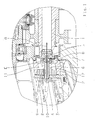
- Referring to FIG. 1 is the flanged to the clutch bell 7 oil pump 2 coaxial arranged to the oiled transmission shaft 1 and is driven by this.
- the leakage oil is passed at least one pump shaft bearing 3 in the executed as a hollow shaft pump shaft 4 and an inner bore having and the pump shaft 4 with the to be oiled transmission shaft 1 connecting carrier 5, passed on to be oiled and also an inner bore having transmission shaft 1.
- the leakage oil flow for internal lubrication of the transmission shaft 1 is in FIG. 1 illustrated by the arrow A.
- the pump shaft bearing is designed as a sliding bearing; According to the invention, the amount of leakage oil can be increased by introducing an axial groove 10 into a first pump shaft bearing 3 in the pump housing.
- the leakage oil of a second bearing 6 of the pump shaft 4, illustrated by arrow D, as well as occurring leakage oil flow losses between the pump shaft 4 and the driver 5, illustrated by arrow E, for lubricating other components of the transmission can be used.
- the lubrication of the pump shaft bearing is improved in that the bearing points 3, 6 of the pump shaft 4 are each connected by a radially extending groove 8, 9 in the pump housing or in the pump cover to the pressure side 11 of the oil pump 2.
- the suction side of the oil pump 2 is provided with the reference numeral 12.
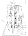
- FIG. 2 Subject of the FIG. 2 is an overview of a transmission 13, in which an inventive device for êtöölung a transmission shaft 1 integrated is.
- the leakage oil flow for internal lubrication of the transmission shaft 1 by arrow A the ⁇ lansaugstrom indicated by arrow B and the pressure oil flow to the oiling points of the transmission by arrow C.
Landscapes
- Engineering & Computer Science (AREA)
- General Engineering & Computer Science (AREA)
- Mechanical Engineering (AREA)
- General Details Of Gearings (AREA)
Claims (10)
- Procédé de lubrification interne d'un arbre de transmission (1) monté de manière coaxiale à la pompe à huile (2) d'une boîte de vitesses (13) et actionnant la pompe à huile (2), dans lequel on effectue la lubrification interne de l'arbre de transmission (1) au moyen de l'huile de fuite de toute façon présente de la pompe à huile (2) intégrée dans la boîte de vitesses (13), caractérisé en ce que l'on conduit l'huile de fuite d'au moins un point d'appui (3) de l'arbre de pompe dans l'arbre de pompe (4) réalisé sous forme d'arbre creux et on la transfère à l'arbre de transmission à lubrifier (1) au moyen d'un entraîneur (5) présentant un alésage interne et reliant l'arbre de pompe (4) à l'arbre de transmission à lubrifier (1).
- Procédé de lubrification interne d'un arbre de transmission (1) selon la revendication 1, caractérisé en ce que, dans le cas où la quantité d'huile de fuite dudit au moins un point d'appui (3) de l'arbre de pompe ne suffit pas pour la lubrification interne de l'arbre de transmission à lubrifier (1), on augmente de façon ciblée la quantité d'huile de fuite dudit au moins un point d'appui (3) de l'arbre de pompe.
- Procédé de lubrification interne d'un arbre de transmission (1) selon la revendication 2, caractérisé en ce que, dans le cas où le palier de l'arbre de pompe est un palier lisse, on augmente la quantité d'huile de fuite par la réalisation d'une rainure axiale (10) dans au moins un point d'appui (3) de l'arbre de pompe dans le boîtier de la pompe.
- Procédé de lubrification interne d'un arbre de transmission (1) selon la revendication 1, 2 ou 3, caractérisé en ce que l'on utilise l'huile de fuite d'un autre point d'appui (6) de l'arbre de pompe (4) ainsi que les pertes d'écoulement d'huile de fuite qui se produisent entre l'arbre de pompe (4) et l'entraîneur (5) pour la lubrification d'autres composants de la boîte de vitesses (13).
- Procédé de lubrification interne d'un arbre de transmission (1) selon la revendication 1, 2, 3 ou 4, caractérisé en ce que l'on améliore la lubrification du palier de l'arbre de pompe, par le fait que les points d'appui (3, 6) de l'arbre de pompe (4) sont raccordés au côté de refoulement (11) de la pompe à huile (2) au moyen d'une rainure respective (8, 9) s'étendant radialement dans le boîtier de pompe ou dans le couvercle de pompe.
- Dispositif de lubrification interne d'un arbre de transmission (1) monté de manière coaxiale à la pompe à huile (2) d'une boîte de vitesses (13) et actionnant la pompe à huile (2), dans lequel il présente des moyens par lesquels l'huile de fuite d'au moins un point d'appui (3) de l'arbre de pompe est transférée à l'arbre de transmission à lubrifier (1), caractérisé en ce que les moyens pour transférer l'huile de fuite à l'arbre de transmission à lubrifier (1) comprennent l'arbre de pompe (4) réalisé sous forme d'arbre creux et un entraîneur (5) présentant un alésage interne et reliant l'arbre de pompe (4) à l'arbre de transmission à lubrifier (1), de telle manière que l'huile de fuite d'au moins un point d'appui (3) de l'arbre de pompe puisse être conduite dans l'arbre de pompe (4) réalisé sous forme d'arbre creux et être transférée à l'arbre de transmission à lubrifier (1) via l'alésage interne de l'entraîneur (5).
- Dispositif de lubrification interne d'un arbre de transmission (1) selon la revendication 6, caractérisé en ce qu'il est prévu des moyens (10) par lesquels la quantité d'huile de fuite dudit au moins un point d'appui (3) de l'arbre de pompe est augmentée de façon ciblée.
- Dispositif de lubrification interne d'un arbre de transmission (1) selon la revendication 7, caractérisé en ce que, dans le cas où le palier de l'arbre de pompe est un palier lisse, les moyens (10) comprennent une rainure axiale (10) dans au moins un point d'appui (3) de l'arbre de pompe dans le boîtier de pompe.
- Dispositif de lubrification interne d'un arbre de transmission (1) selon l'une quelconque des revendications 6 à 8, caractérisé en ce que l'huile de fuite d'un autre point d'appui (6) de l'arbre de pompe (4) ainsi que des pertes d'écoulement d'huile de fuite se produisant entre l'arbre de pompe (4) et l'entraîneur (5) peuvent être utilisées pour la lubrification d'autres composants de la boîte de vitesses (13).
- Dispositif de lubrification interne d'un arbre de transmission (1) selon le préambule de la revendication 6 ou selon l'une quelconque des revendications 6 à 9, caractérisé en ce que, pour améliorer la lubrification du palier de l'arbre de pompe, les points d'appui (3, 6) de l'arbre de pompe (4) sont raccordés au côté de refoulement (11) de la pompe à huile (2) au moyen d'une rainure respective (8, 9) s'étendant radialement dans le boîtier de pompe ou dans le couvercle de pompe.
Applications Claiming Priority (2)
| Application Number | Priority Date | Filing Date | Title |
|---|---|---|---|
| DE102010021894.4A DE102010021894B4 (de) | 2010-05-28 | 2010-05-28 | Verfahren und Einrichtung zur Innenbeölung einer koaxial zur Ölpumpe eines Getriebes angeordneten und die Ölpumpe antreibenden Getriebewelle |
| PCT/EP2011/055163 WO2011147615A1 (fr) | 2010-05-28 | 2011-04-04 | Procédé et dispositif de lubrification interne d'un arbre de transmission, monté de manière coaxiale à la pompe à huile d'une boîte de vitesse et actionnant la pompe à huile |
Publications (2)
| Publication Number | Publication Date |
|---|---|
| EP2577112A1 EP2577112A1 (fr) | 2013-04-10 |
| EP2577112B1 true EP2577112B1 (fr) | 2015-11-04 |
Family
ID=44210348
Family Applications (1)
| Application Number | Title | Priority Date | Filing Date |
|---|---|---|---|
| EP11714013.7A Not-in-force EP2577112B1 (fr) | 2010-05-28 | 2011-04-04 | Procede et dispositif de lubrification interne d'un arbre de transmission, monte de maniere coaxiale a la pompe a huile d'une boite de vitesse et actionnant la pompe a huile |
Country Status (5)
| Country | Link |
|---|---|
| US (1) | US9188216B2 (fr) |
| EP (1) | EP2577112B1 (fr) |
| CN (1) | CN102859237B (fr) |
| DE (1) | DE102010021894B4 (fr) |
| WO (1) | WO2011147615A1 (fr) |
Families Citing this family (6)
| Publication number | Priority date | Publication date | Assignee | Title |
|---|---|---|---|---|
| CN102777478A (zh) * | 2012-07-13 | 2012-11-14 | 无锡市聚英机械制造有限公司 | 一种减速机用空心轴 |
| WO2014133669A1 (fr) * | 2013-02-26 | 2014-09-04 | United Technologies Corporation | Lubrification d'un palier lisse durant une rotation en sens horaire et en sens antihoraire |
| DE102015205986A1 (de) * | 2015-04-02 | 2016-10-06 | Zf Friedrichshafen Ag | Verteilergetriebeanordnung |
| DE102016213611B4 (de) | 2016-07-25 | 2022-12-01 | Zf Friedrichshafen Ag | Rotorpumpe und Anordnung zum Antrieb einer Rotorpumpe |
| CN109340367A (zh) * | 2018-11-05 | 2019-02-15 | 绿传(北京)科技有限公司 | 一种用于变速器的外置油泵 |
| CN109237009A (zh) * | 2018-11-05 | 2019-01-18 | 绿传(北京)科技有限公司 | 一种具有外置双油泵的自动变速器 |
Citations (3)
| Publication number | Priority date | Publication date | Assignee | Title |
|---|---|---|---|---|
| DE3939651C1 (fr) * | 1989-11-30 | 1991-05-08 | Mercedes-Benz Aktiengesellschaft, 7000 Stuttgart, De | |
| EP0985852A2 (fr) * | 1998-09-08 | 2000-03-15 | General Motors Corporation | Accouplement de pontage à fluide pour convertisseur de couple et son dispositif d'étanchéité |
| US20080191422A1 (en) * | 2007-02-12 | 2008-08-14 | Norman Schoenek | Transmission pump seal |
Family Cites Families (26)
| Publication number | Priority date | Publication date | Assignee | Title |
|---|---|---|---|---|
| US3065822A (en) * | 1960-12-12 | 1962-11-27 | Int Harvester Co | Lubricating means for a power transmission |
| BE756886A (fr) * | 1970-01-02 | 1971-03-01 | Gen Electric | Pompe de dosage et d'evacuation |
| US3889489A (en) * | 1974-08-23 | 1975-06-17 | Gen Motors Corp | Lubricated spline coupling |
| US4458318A (en) * | 1981-04-24 | 1984-07-03 | Borg-Warner Corporation | Control arrangement for a variable pulley transmission |
| US4494943A (en) * | 1981-09-08 | 1985-01-22 | Nippondenso Co., Ltd. | Power transmission device for vehicles |
| US4669999A (en) * | 1984-08-22 | 1987-06-02 | Sundstrand Corporation | Lubricant delivering and containment overload shearable coupling |
| AT389739B (de) * | 1984-09-21 | 1990-01-25 | Avl Verbrennungskraft Messtech | Viertakt-brennkraftmaschine mit einer als zahnradpumpe ausgebildeten schmieroelpumpe |
| US4784630A (en) * | 1986-12-17 | 1988-11-15 | Fuji Jukogyo Kabushiki Kaisha | Rotating speed detecting device for a continuously variable transmission for a vehicle |
| US4789316A (en) * | 1986-12-29 | 1988-12-06 | Ingersoll-Rand Company | Gear lubrication pump for an air motor |
| US4747808A (en) * | 1987-01-08 | 1988-05-31 | Ford Motor Company | System for actuating the displaceable pulley in a continually variable transmission |
| DE3905770A1 (de) | 1988-03-02 | 1989-09-14 | Zahnradfabrik Friedrichshafen | Verfahren und vorrichtung zur reinigung von schmieroel im getriebe |
| JP3223215B2 (ja) * | 1993-07-22 | 2001-10-29 | 本田技研工業株式会社 | 歯車変速機 |
| JP3097439B2 (ja) * | 1994-03-17 | 2000-10-10 | 日産自動車株式会社 | 無段変速機の油路構造 |
| US5474152A (en) * | 1995-04-12 | 1995-12-12 | Teledyne Industries, Inc. | Lubrication system for a starter clutch assembly |
| JPH10318357A (ja) * | 1997-05-16 | 1998-12-04 | Jatco Corp | 変速機の潤滑構造 |
| JPH1151161A (ja) * | 1997-07-31 | 1999-02-23 | Aichi Mach Ind Co Ltd | 変速機用ベアリングの潤滑構造 |
| JP2002098171A (ja) * | 2000-09-21 | 2002-04-05 | Jatco Transtechnology Ltd | 自動変速機の発進クラッチ潤滑制御装置 |
| DE102004018226B4 (de) * | 2004-04-15 | 2011-07-28 | ZF Friedrichshafen AG, 88046 | Einrichtung zur Ölversorgung von Wellen, welche eine axial verlaufende Bohrung bzw. Öldurchführung ausweisen |
| JP4350692B2 (ja) * | 2005-09-21 | 2009-10-21 | ジヤトコ株式会社 | 自動変速装置 |
| DE102005052450A1 (de) * | 2005-11-03 | 2007-06-14 | Zf Friedrichshafen Ag | Einrichtung zum Beölen von Bauteilen mittels drehender Wellen |
| JP4688769B2 (ja) * | 2006-09-27 | 2011-05-25 | 本田技研工業株式会社 | 内燃機関のオイルポンプユニット |
| US8312858B2 (en) * | 2006-12-22 | 2012-11-20 | Kohler Co. | System and method for lubricating power transmitting elements |
| US8641394B2 (en) * | 2008-02-28 | 2014-02-04 | Daikin Industries, Ltd. | Compressor |
| JP4616376B2 (ja) * | 2008-09-04 | 2011-01-19 | ジヤトコ株式会社 | 自動変速機における筒状部材の支持構造 |
| JP5206457B2 (ja) * | 2009-02-03 | 2013-06-12 | コベルコ建機株式会社 | ハイブリッド作業機械の軸潤滑装置 |
| DE112010003517T5 (de) * | 2009-09-25 | 2012-12-20 | Aisin Aw Co., Ltd. | Antriebsvorrichtung |
-
2010
- 2010-05-28 DE DE102010021894.4A patent/DE102010021894B4/de not_active Expired - Fee Related
-
2011
- 2011-04-04 WO PCT/EP2011/055163 patent/WO2011147615A1/fr active Application Filing
- 2011-04-04 EP EP11714013.7A patent/EP2577112B1/fr not_active Not-in-force
- 2011-04-04 US US13/700,165 patent/US9188216B2/en not_active Expired - Fee Related
- 2011-04-04 CN CN201180020075.0A patent/CN102859237B/zh not_active Expired - Fee Related
Patent Citations (3)
| Publication number | Priority date | Publication date | Assignee | Title |
|---|---|---|---|---|
| DE3939651C1 (fr) * | 1989-11-30 | 1991-05-08 | Mercedes-Benz Aktiengesellschaft, 7000 Stuttgart, De | |
| EP0985852A2 (fr) * | 1998-09-08 | 2000-03-15 | General Motors Corporation | Accouplement de pontage à fluide pour convertisseur de couple et son dispositif d'étanchéité |
| US20080191422A1 (en) * | 2007-02-12 | 2008-08-14 | Norman Schoenek | Transmission pump seal |
Also Published As
| Publication number | Publication date |
|---|---|
| DE102010021894B4 (de) | 2015-07-09 |
| EP2577112A1 (fr) | 2013-04-10 |
| DE102010021894A1 (de) | 2011-12-01 |
| US9188216B2 (en) | 2015-11-17 |
| WO2011147615A1 (fr) | 2011-12-01 |
| US20130233650A1 (en) | 2013-09-12 |
| CN102859237B (zh) | 2016-03-02 |
| CN102859237A (zh) | 2013-01-02 |
Similar Documents
| Publication | Publication Date | Title |
|---|---|---|
| EP2577112B1 (fr) | Procede et dispositif de lubrification interne d'un arbre de transmission, monte de maniere coaxiale a la pompe a huile d'une boite de vitesse et actionnant la pompe a huile | |
| DE112009002476T5 (de) | Einspeisungssystem für Differentialgetriebeschmiermittel in einer Antriebsachsanordnung | |
| DE102015218280B4 (de) | Elektrische Maschine und Kraftfahrzeug | |
| DE102016114403B4 (de) | Zapfwellen-system für ein kraftfahrzeug, das der ausrückkupplung ölablass und drucköl bereitstellt | |
| DE102018203696A1 (de) | System mit einem Schmierölkreislauf und mit einem Kühlölkreislauf | |
| DE102019201586A1 (de) | Ölbehälter zur Kühlung und/oder Schmierung von Lagern eines Antriebsstranges eines Fahrzeuges, insbesondere eines Kraftfahrzeuges | |
| DE102012222795A1 (de) | Kraftfahrzeug mit einem Antriebsmotor und einer Vorrichtung zur Erzeugung eines Unterdrucks für einen Servoverbraucher | |
| DE102014210774B4 (de) | Hydraulischer Antrieb mit einer verstellbaren hydraulischen Axialkolbenmaschine in Dry-Case Bauweise | |
| DE102005052451A1 (de) | Einrichtung zur Steuerung des Volumenstroms in innenbeölten Wellen | |
| EP1600666B1 (fr) | Dispositif hydromécanique d'entrainement d'un véhicule | |
| DE102021200276A1 (de) | Vorrichtung zum Kühlen und Schmieren von Komponenten eines Fahrzeugs sowie Antriebsvorrichtung mit einer solchen Vorrichtung | |
| DE102012010181A1 (de) | Kraftfahrzeugantriebsstrang | |
| DE102013224499A1 (de) | Optimierte Getriebeanordnung | |
| DE112013005092B4 (de) | Kupplungsbeölung | |
| WO2018077687A1 (fr) | Groupe motopropulseur, en particulier groupe motopropulseur hybride pour un véhicule à moteur | |
| DE102020120419A1 (de) | Ölzuführvorrichtung für einen Getriebeabschnitt sowie Getriebeabschnitt mit der Ölzuführvorrichtung | |
| DE102021200278A1 (de) | Vorrichtung zum Kühlen und Schmieren von Komponenten eines Fahrzeugs sowie Antriebsvorrichtung mit einer solchen Vorrichtung | |
| DE202010007319U1 (de) | Einrichtung zur Innenbeölung einer koaxial zur Ölpumpe eines Getriebes angeordneten und die Ölpumpe antreibenden Getriebewelle | |
| WO2006122687A1 (fr) | Dispositif de lubrification de composants d'un vehicule automobile | |
| DE10329762A1 (de) | Abdeckplatte für ein Kurbelgehäuse | |
| EP3532748A1 (fr) | Groupe motopropulseur, en particulier groupe motopropulseur hybride pour un véhicule à moteur | |
| DE102018218946A1 (de) | Teilummantelung einer Antriebseinheit mittels eines dünnwandigen, mit seinen Enden in einem Getriebegehäuse fixierten Abschirmelements | |
| DE202008010126U1 (de) | Ölpumpe eines automatisierten Kraftfahrzeug-Getriebes | |
| EP4015877A1 (fr) | Engrenage d'essieu électrique, adapté pour la marche avant et la marche arrière | |
| DE102020208812A1 (de) | Getriebe |
Legal Events
| Date | Code | Title | Description |
|---|---|---|---|
| PUAI | Public reference made under article 153(3) epc to a published international application that has entered the european phase |
Free format text: ORIGINAL CODE: 0009012 |
|
| 17P | Request for examination filed |
Effective date: 20121002 |
|
| AK | Designated contracting states |
Kind code of ref document: A1 Designated state(s): AL AT BE BG CH CY CZ DE DK EE ES FI FR GB GR HR HU IE IS IT LI LT LU LV MC MK MT NL NO PL PT RO RS SE SI SK SM TR |
|
| DAX | Request for extension of the european patent (deleted) | ||
| 17Q | First examination report despatched |
Effective date: 20140704 |
|
| GRAP | Despatch of communication of intention to grant a patent |
Free format text: ORIGINAL CODE: EPIDOSNIGR1 |
|
| INTG | Intention to grant announced |
Effective date: 20150618 |
|
| GRAS | Grant fee paid |
Free format text: ORIGINAL CODE: EPIDOSNIGR3 |
|
| GRAA | (expected) grant |
Free format text: ORIGINAL CODE: 0009210 |
|
| AK | Designated contracting states |
Kind code of ref document: B1 Designated state(s): AL AT BE BG CH CY CZ DE DK EE ES FI FR GB GR HR HU IE IS IT LI LT LU LV MC MK MT NL NO PL PT RO RS SE SI SK SM TR |
|
| REG | Reference to a national code |
Ref country code: GB Ref legal event code: FG4D Free format text: NOT ENGLISH |
|
| REG | Reference to a national code |
Ref country code: CH Ref legal event code: EP |
|
| REG | Reference to a national code |
Ref country code: AT Ref legal event code: REF Ref document number: 759436 Country of ref document: AT Kind code of ref document: T Effective date: 20151115 |
|
| REG | Reference to a national code |
Ref country code: IE Ref legal event code: FG4D Free format text: LANGUAGE OF EP DOCUMENT: GERMAN |
|
| REG | Reference to a national code |
Ref country code: DE Ref legal event code: R096 Ref document number: 502011008273 Country of ref document: DE |
|
| REG | Reference to a national code |
Ref country code: NL Ref legal event code: MP Effective date: 20151104 |
|
| REG | Reference to a national code |
Ref country code: LT Ref legal event code: MG4D |
|
| PG25 | Lapsed in a contracting state [announced via postgrant information from national office to epo] |
Ref country code: IT Free format text: LAPSE BECAUSE OF FAILURE TO SUBMIT A TRANSLATION OF THE DESCRIPTION OR TO PAY THE FEE WITHIN THE PRESCRIBED TIME-LIMIT Effective date: 20151104 Ref country code: NO Free format text: LAPSE BECAUSE OF FAILURE TO SUBMIT A TRANSLATION OF THE DESCRIPTION OR TO PAY THE FEE WITHIN THE PRESCRIBED TIME-LIMIT Effective date: 20160204 Ref country code: LT Free format text: LAPSE BECAUSE OF FAILURE TO SUBMIT A TRANSLATION OF THE DESCRIPTION OR TO PAY THE FEE WITHIN THE PRESCRIBED TIME-LIMIT Effective date: 20151104 Ref country code: IS Free format text: LAPSE BECAUSE OF FAILURE TO SUBMIT A TRANSLATION OF THE DESCRIPTION OR TO PAY THE FEE WITHIN THE PRESCRIBED TIME-LIMIT Effective date: 20160304 Ref country code: NL Free format text: LAPSE BECAUSE OF FAILURE TO SUBMIT A TRANSLATION OF THE DESCRIPTION OR TO PAY THE FEE WITHIN THE PRESCRIBED TIME-LIMIT Effective date: 20151104 Ref country code: ES Free format text: LAPSE BECAUSE OF FAILURE TO SUBMIT A TRANSLATION OF THE DESCRIPTION OR TO PAY THE FEE WITHIN THE PRESCRIBED TIME-LIMIT Effective date: 20151104 Ref country code: HR Free format text: LAPSE BECAUSE OF FAILURE TO SUBMIT A TRANSLATION OF THE DESCRIPTION OR TO PAY THE FEE WITHIN THE PRESCRIBED TIME-LIMIT Effective date: 20151104 |
|
| PG25 | Lapsed in a contracting state [announced via postgrant information from national office to epo] |
Ref country code: LV Free format text: LAPSE BECAUSE OF FAILURE TO SUBMIT A TRANSLATION OF THE DESCRIPTION OR TO PAY THE FEE WITHIN THE PRESCRIBED TIME-LIMIT Effective date: 20151104 Ref country code: PT Free format text: LAPSE BECAUSE OF FAILURE TO SUBMIT A TRANSLATION OF THE DESCRIPTION OR TO PAY THE FEE WITHIN THE PRESCRIBED TIME-LIMIT Effective date: 20160304 Ref country code: RS Free format text: LAPSE BECAUSE OF FAILURE TO SUBMIT A TRANSLATION OF THE DESCRIPTION OR TO PAY THE FEE WITHIN THE PRESCRIBED TIME-LIMIT Effective date: 20151104 Ref country code: SE Free format text: LAPSE BECAUSE OF FAILURE TO SUBMIT A TRANSLATION OF THE DESCRIPTION OR TO PAY THE FEE WITHIN THE PRESCRIBED TIME-LIMIT Effective date: 20151104 Ref country code: PL Free format text: LAPSE BECAUSE OF FAILURE TO SUBMIT A TRANSLATION OF THE DESCRIPTION OR TO PAY THE FEE WITHIN THE PRESCRIBED TIME-LIMIT Effective date: 20151104 Ref country code: GR Free format text: LAPSE BECAUSE OF FAILURE TO SUBMIT A TRANSLATION OF THE DESCRIPTION OR TO PAY THE FEE WITHIN THE PRESCRIBED TIME-LIMIT Effective date: 20160205 Ref country code: FI Free format text: LAPSE BECAUSE OF FAILURE TO SUBMIT A TRANSLATION OF THE DESCRIPTION OR TO PAY THE FEE WITHIN THE PRESCRIBED TIME-LIMIT Effective date: 20151104 |
|
| PG25 | Lapsed in a contracting state [announced via postgrant information from national office to epo] |
Ref country code: CZ Free format text: LAPSE BECAUSE OF FAILURE TO SUBMIT A TRANSLATION OF THE DESCRIPTION OR TO PAY THE FEE WITHIN THE PRESCRIBED TIME-LIMIT Effective date: 20151104 |
|
| REG | Reference to a national code |
Ref country code: DE Ref legal event code: R097 Ref document number: 502011008273 Country of ref document: DE |
|
| PG25 | Lapsed in a contracting state [announced via postgrant information from national office to epo] |
Ref country code: DK Free format text: LAPSE BECAUSE OF FAILURE TO SUBMIT A TRANSLATION OF THE DESCRIPTION OR TO PAY THE FEE WITHIN THE PRESCRIBED TIME-LIMIT Effective date: 20151104 Ref country code: SK Free format text: LAPSE BECAUSE OF FAILURE TO SUBMIT A TRANSLATION OF THE DESCRIPTION OR TO PAY THE FEE WITHIN THE PRESCRIBED TIME-LIMIT Effective date: 20151104 Ref country code: RO Free format text: LAPSE BECAUSE OF FAILURE TO SUBMIT A TRANSLATION OF THE DESCRIPTION OR TO PAY THE FEE WITHIN THE PRESCRIBED TIME-LIMIT Effective date: 20151104 Ref country code: EE Free format text: LAPSE BECAUSE OF FAILURE TO SUBMIT A TRANSLATION OF THE DESCRIPTION OR TO PAY THE FEE WITHIN THE PRESCRIBED TIME-LIMIT Effective date: 20151104 Ref country code: SM Free format text: LAPSE BECAUSE OF FAILURE TO SUBMIT A TRANSLATION OF THE DESCRIPTION OR TO PAY THE FEE WITHIN THE PRESCRIBED TIME-LIMIT Effective date: 20151104 Ref country code: BE Free format text: LAPSE BECAUSE OF NON-PAYMENT OF DUE FEES Effective date: 20160430 |
|
| PLBE | No opposition filed within time limit |
Free format text: ORIGINAL CODE: 0009261 |
|
| STAA | Information on the status of an ep patent application or granted ep patent |
Free format text: STATUS: NO OPPOSITION FILED WITHIN TIME LIMIT |
|
| 26N | No opposition filed |
Effective date: 20160805 |
|
| PG25 | Lapsed in a contracting state [announced via postgrant information from national office to epo] |
Ref country code: SI Free format text: LAPSE BECAUSE OF FAILURE TO SUBMIT A TRANSLATION OF THE DESCRIPTION OR TO PAY THE FEE WITHIN THE PRESCRIBED TIME-LIMIT Effective date: 20151104 |
|
| REG | Reference to a national code |
Ref country code: CH Ref legal event code: PL |
|
| GBPC | Gb: european patent ceased through non-payment of renewal fee |
Effective date: 20160404 |
|
| PG25 | Lapsed in a contracting state [announced via postgrant information from national office to epo] |
Ref country code: LU Free format text: LAPSE BECAUSE OF FAILURE TO SUBMIT A TRANSLATION OF THE DESCRIPTION OR TO PAY THE FEE WITHIN THE PRESCRIBED TIME-LIMIT Effective date: 20160404 |
|
| REG | Reference to a national code |
Ref country code: IE Ref legal event code: MM4A |
|
| REG | Reference to a national code |
Ref country code: FR Ref legal event code: ST Effective date: 20161230 |
|
| PG25 | Lapsed in a contracting state [announced via postgrant information from national office to epo] |
Ref country code: LI Free format text: LAPSE BECAUSE OF NON-PAYMENT OF DUE FEES Effective date: 20160430 Ref country code: GB Free format text: LAPSE BECAUSE OF NON-PAYMENT OF DUE FEES Effective date: 20160404 Ref country code: CH Free format text: LAPSE BECAUSE OF NON-PAYMENT OF DUE FEES Effective date: 20160430 Ref country code: FR Free format text: LAPSE BECAUSE OF NON-PAYMENT OF DUE FEES Effective date: 20160502 |
|
| PG25 | Lapsed in a contracting state [announced via postgrant information from national office to epo] |
Ref country code: IE Free format text: LAPSE BECAUSE OF NON-PAYMENT OF DUE FEES Effective date: 20160404 |
|
| REG | Reference to a national code |
Ref country code: AT Ref legal event code: MM01 Ref document number: 759436 Country of ref document: AT Kind code of ref document: T Effective date: 20160404 |
|
| PG25 | Lapsed in a contracting state [announced via postgrant information from national office to epo] |
Ref country code: AT Free format text: LAPSE BECAUSE OF NON-PAYMENT OF DUE FEES Effective date: 20160404 |
|
| PG25 | Lapsed in a contracting state [announced via postgrant information from national office to epo] |
Ref country code: CY Free format text: LAPSE BECAUSE OF FAILURE TO SUBMIT A TRANSLATION OF THE DESCRIPTION OR TO PAY THE FEE WITHIN THE PRESCRIBED TIME-LIMIT Effective date: 20151104 Ref country code: HU Free format text: LAPSE BECAUSE OF FAILURE TO SUBMIT A TRANSLATION OF THE DESCRIPTION OR TO PAY THE FEE WITHIN THE PRESCRIBED TIME-LIMIT; INVALID AB INITIO Effective date: 20110404 |
|
| PG25 | Lapsed in a contracting state [announced via postgrant information from national office to epo] |
Ref country code: MC Free format text: LAPSE BECAUSE OF FAILURE TO SUBMIT A TRANSLATION OF THE DESCRIPTION OR TO PAY THE FEE WITHIN THE PRESCRIBED TIME-LIMIT Effective date: 20151104 Ref country code: MT Free format text: LAPSE BECAUSE OF FAILURE TO SUBMIT A TRANSLATION OF THE DESCRIPTION OR TO PAY THE FEE WITHIN THE PRESCRIBED TIME-LIMIT Effective date: 20151104 Ref country code: MK Free format text: LAPSE BECAUSE OF FAILURE TO SUBMIT A TRANSLATION OF THE DESCRIPTION OR TO PAY THE FEE WITHIN THE PRESCRIBED TIME-LIMIT Effective date: 20151104 Ref country code: TR Free format text: LAPSE BECAUSE OF FAILURE TO SUBMIT A TRANSLATION OF THE DESCRIPTION OR TO PAY THE FEE WITHIN THE PRESCRIBED TIME-LIMIT Effective date: 20151104 |
|
| PG25 | Lapsed in a contracting state [announced via postgrant information from national office to epo] |
Ref country code: BG Free format text: LAPSE BECAUSE OF FAILURE TO SUBMIT A TRANSLATION OF THE DESCRIPTION OR TO PAY THE FEE WITHIN THE PRESCRIBED TIME-LIMIT Effective date: 20151104 |
|
| PG25 | Lapsed in a contracting state [announced via postgrant information from national office to epo] |
Ref country code: AL Free format text: LAPSE BECAUSE OF FAILURE TO SUBMIT A TRANSLATION OF THE DESCRIPTION OR TO PAY THE FEE WITHIN THE PRESCRIBED TIME-LIMIT Effective date: 20151104 |
|
| PGFP | Annual fee paid to national office [announced via postgrant information from national office to epo] |
Ref country code: DE Payment date: 20220302 Year of fee payment: 12 |
|
| REG | Reference to a national code |
Ref country code: DE Ref legal event code: R119 Ref document number: 502011008273 Country of ref document: DE |
|
| PG25 | Lapsed in a contracting state [announced via postgrant information from national office to epo] |
Ref country code: DE Free format text: LAPSE BECAUSE OF NON-PAYMENT OF DUE FEES Effective date: 20231103 |