EP2577112B1 - Method and device for the internal oiling of a gear shaft that is arranged coaxially to the oil pump of a gearbox and drives the oil pump - Google Patents
Method and device for the internal oiling of a gear shaft that is arranged coaxially to the oil pump of a gearbox and drives the oil pump Download PDFInfo
- Publication number
- EP2577112B1 EP2577112B1 EP11714013.7A EP11714013A EP2577112B1 EP 2577112 B1 EP2577112 B1 EP 2577112B1 EP 11714013 A EP11714013 A EP 11714013A EP 2577112 B1 EP2577112 B1 EP 2577112B1
- Authority
- EP
- European Patent Office
- Prior art keywords
- pump
- shaft
- oil
- transmission
- transmission shaft
- Prior art date
- Legal status (The legal status is an assumption and is not a legal conclusion. Google has not performed a legal analysis and makes no representation as to the accuracy of the status listed.)
- Not-in-force
Links
- 238000000034 method Methods 0.000 title claims description 15
- 230000005540 biological transmission Effects 0.000 claims description 61
- 238000005461 lubrication Methods 0.000 claims description 44
- 230000001050 lubricating effect Effects 0.000 claims description 5
- 239000003921 oil Substances 0.000 description 75
- 238000002347 injection Methods 0.000 description 3
- 239000007924 injection Substances 0.000 description 3
- 230000001419 dependent effect Effects 0.000 description 1
- 230000000694 effects Effects 0.000 description 1
- 239000010687 lubricating oil Substances 0.000 description 1
- 238000012423 maintenance Methods 0.000 description 1
- 238000004519 manufacturing process Methods 0.000 description 1
- 238000005086 pumping Methods 0.000 description 1
- 230000001105 regulatory effect Effects 0.000 description 1
- 238000005096 rolling process Methods 0.000 description 1
Images
Classifications
-
- F—MECHANICAL ENGINEERING; LIGHTING; HEATING; WEAPONS; BLASTING
- F16—ENGINEERING ELEMENTS AND UNITS; GENERAL MEASURES FOR PRODUCING AND MAINTAINING EFFECTIVE FUNCTIONING OF MACHINES OR INSTALLATIONS; THERMAL INSULATION IN GENERAL
- F16H—GEARING
- F16H57/00—General details of gearing
- F16H57/04—Features relating to lubrication or cooling or heating
- F16H57/0434—Features relating to lubrication or cooling or heating relating to lubrication supply, e.g. pumps ; Pressure control
- F16H57/0436—Pumps
-
- F—MECHANICAL ENGINEERING; LIGHTING; HEATING; WEAPONS; BLASTING
- F01—MACHINES OR ENGINES IN GENERAL; ENGINE PLANTS IN GENERAL; STEAM ENGINES
- F01M—LUBRICATING OF MACHINES OR ENGINES IN GENERAL; LUBRICATING INTERNAL COMBUSTION ENGINES; CRANKCASE VENTILATING
- F01M1/00—Pressure lubrication
- F01M1/02—Pressure lubrication using lubricating pumps
-
- F—MECHANICAL ENGINEERING; LIGHTING; HEATING; WEAPONS; BLASTING
- F01—MACHINES OR ENGINES IN GENERAL; ENGINE PLANTS IN GENERAL; STEAM ENGINES
- F01M—LUBRICATING OF MACHINES OR ENGINES IN GENERAL; LUBRICATING INTERNAL COMBUSTION ENGINES; CRANKCASE VENTILATING
- F01M11/00—Component parts, details or accessories, not provided for in, or of interest apart from, groups F01M1/00 - F01M9/00
- F01M11/02—Arrangements of lubricant conduits
-
- F—MECHANICAL ENGINEERING; LIGHTING; HEATING; WEAPONS; BLASTING
- F16—ENGINEERING ELEMENTS AND UNITS; GENERAL MEASURES FOR PRODUCING AND MAINTAINING EFFECTIVE FUNCTIONING OF MACHINES OR INSTALLATIONS; THERMAL INSULATION IN GENERAL
- F16H—GEARING
- F16H57/00—General details of gearing
- F16H57/04—Features relating to lubrication or cooling or heating
- F16H57/042—Guidance of lubricant
- F16H57/043—Guidance of lubricant within rotary parts, e.g. axial channels or radial openings in shafts
-
- F—MECHANICAL ENGINEERING; LIGHTING; HEATING; WEAPONS; BLASTING
- F16—ENGINEERING ELEMENTS AND UNITS; GENERAL MEASURES FOR PRODUCING AND MAINTAINING EFFECTIVE FUNCTIONING OF MACHINES OR INSTALLATIONS; THERMAL INSULATION IN GENERAL
- F16H—GEARING
- F16H57/00—General details of gearing
- F16H57/04—Features relating to lubrication or cooling or heating
- F16H57/0434—Features relating to lubrication or cooling or heating relating to lubrication supply, e.g. pumps ; Pressure control
- F16H57/0441—Arrangements of pumps
-
- F—MECHANICAL ENGINEERING; LIGHTING; HEATING; WEAPONS; BLASTING
- F16—ENGINEERING ELEMENTS AND UNITS; GENERAL MEASURES FOR PRODUCING AND MAINTAINING EFFECTIVE FUNCTIONING OF MACHINES OR INSTALLATIONS; THERMAL INSULATION IN GENERAL
- F16H—GEARING
- F16H57/00—General details of gearing
- F16H57/04—Features relating to lubrication or cooling or heating
- F16H57/048—Type of gearings to be lubricated, cooled or heated
- F16H57/0493—Gearings with spur or bevel gears
- F16H57/0494—Gearings with spur or bevel gears with variable gear ratio or for reversing rotary motion
Definitions
- the present invention relates to a method for internal lubrication of a coaxial with the oil pump of a transmission arranged and the oil pump driving gear shaft according to the preamble of claim 1. Furthermore, the invention relates to a device for êtbeölung a coaxial with the oil pump of a transmission arranged and the oil pump driving Transmission shaft, in particular for carrying out the method according to the invention.
- the internal lubrication of transmission shafts can be done by passive lubrication systems, which use special ⁇ lleit drivingen which collect the oil by means of drip edges in the housing or ⁇ lfang Roaden and lead via channels to one end of the gear shaft to be oiled; the oil is passed into the shaft by means of a oil guide protruding into the shaft at one end of the gear shaft to be oiled or by means of a rotary feedthrough.
- the applicant is a device for oiling components by means of rotating shafts, for example in motor vehicle automatic transmissions or other devices with rotating components, known.
- the known device comprises at least two hollow shafts arranged in the direction of flow of the oil, wherein a main shaft is arranged coaxially in a receiving region of a drive shaft and mounted therein via a roller bearing.
- a main shaft is arranged coaxially in a receiving region of a drive shaft and mounted therein via a roller bearing.
- the internal lubrication of transmission shafts can be ensured by active lubrication systems.
- the oil is pumped by a pump and an oil line system to an injection nozzle at the end of the gear shaft to be oiled or to a rotary union and injected into the shaft.
- additional components such as e.g. ⁇ lleit Anlagenen, an injection nozzle and a rotary feedthrough required.
- the Applicant for oil supply of shafts, in particular transmission shafts, which have an axially extending bore or oil passage, known, which has at least one provided in the axially extending bore or oil passage provided with the shaft from the surface of the shaft in the axially extending bore or oil passage leads. Furthermore, the known device has at least one nozzle arranged outside the shaft, via which oil is injected into the at least one oil hole, wherein the injection speed of the oil is determined so that the jet reaches at least until the oil passage in the shaft, where it decays and distributed in the wave.
- the present invention has for its object to provide a method for internal lubrication of a coaxial with the oil pump of a transmission arranged and drive the oil pump drive shaft, through its implementation less additional components are required, as in the known from the prior art method.
- Another object of the invention is to provide a device for internal lubrication of a coaxial with the oil pump of a transmission and the oil pump driving gear shaft, in particular for carrying out the inventive specify method, which has a small number of additional components and ensures an effective internal lubrication.
- the integrated in the transmission oil pump is driven by the gear shaft to be oiled and is arranged coaxially to this and preferably flanged to the clutch bell.
- the leakage oil is passed at least one pump shaft bearing point in the executed as a hollow shaft pump shaft.
- the bearing points of the pump shaft may be connected by a respective groove in the pump housing or in the pump cover with the pressure side of the pump.
- the oil is forwarded in the gear shaft to be oiled via a driver, which has an inner bore and connects the pump shaft with the gear shaft to be oiled frictionally.
- a driver which has an inner bore and connects the pump shaft with the gear shaft to be oiled frictionally.
- the leakage oil quantity is selectively increased by suitable measures on at least one pump shaft bearing point according to an embodiment of the invention.
- the amount of leakage oil can be increased by introducing an axial groove into at least one pump shaft bearing point in the pump housing.
- the leakage oil of a further bearing point of the pump shaft and occurring leakage oil flow losses between the pump shaft and the driver by suitable measures for lubrication of other components of the transmission, such as bearings, are used.
- the device according to the invention for internal lubrication of a coaxial with the oil pump of a transmission arranged and the oil pump driving gear shaft has, according to the invention means via which the leakage oil at least one pump shaft bearing point is forwarded to the gear shaft to be oiled.
- means via which the leakage oil at least one pump shaft bearing point is forwarded to the gear shaft to be oiled are provided as a means for forwarding the leakage oil to the gear shaft to be oiled, on the one hand according to the invention designed as a hollow shaft pump shaft and on the other hand, an inner bore having driver; the leakage oil of at least one pump shaft bearing point can be conducted into the pump shaft designed as a hollow shaft and forwarded via the inner bore of the driver to the gear shaft to be oiled.
- the device for internal lubrication of a transmission shaft optionally comprises means by which the amount of leakage oil of the at least one pump shaft bearing point is specifically increased, wherein in the event that the pump shaft bearing is designed as a sliding bearing, the means comprise an axial groove in at least one pump shaft bearing point in the pump housing.
- the device can be constructed in such a way that the leakage oil of a further bearing point of the pump shaft and occurring leakage oil flow losses between the pump shaft and the driver can be used for lubricating further components of the transmission.
- the bearing points of the pump shaft can be connected by a respective radially extending groove in the pump housing or in the pump cover with the pressure side of the oil pump.
- the concept of the invention ensures the lubrication of a gear shaft or the components mounted on the gear shaft and the shaft bearing in the transmission, wherein the already existing leakage oil of the oil pump integrated in the transmission is used in an advantageous manner.
- the concept of the invention the full capacity of the oil pump and thus more oil for the other lubrication points of the transmission available. It is also possible to make the oil pump smaller, whereby an increase in efficiency is achieved.
- the internal lubrication of a gear shaft is carried out by the already existing leakage oil of the oil pump integrated in the transmission.
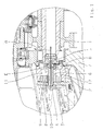
- Referring to FIG. 1 is the flanged to the clutch bell 7 oil pump 2 coaxial arranged to the oiled transmission shaft 1 and is driven by this.
- the leakage oil is passed at least one pump shaft bearing 3 in the executed as a hollow shaft pump shaft 4 and an inner bore having and the pump shaft 4 with the to be oiled transmission shaft 1 connecting carrier 5, passed on to be oiled and also an inner bore having transmission shaft 1.
- the leakage oil flow for internal lubrication of the transmission shaft 1 is in FIG. 1 illustrated by the arrow A.
- the pump shaft bearing is designed as a sliding bearing; According to the invention, the amount of leakage oil can be increased by introducing an axial groove 10 into a first pump shaft bearing 3 in the pump housing.
- the leakage oil of a second bearing 6 of the pump shaft 4, illustrated by arrow D, as well as occurring leakage oil flow losses between the pump shaft 4 and the driver 5, illustrated by arrow E, for lubricating other components of the transmission can be used.
- the lubrication of the pump shaft bearing is improved in that the bearing points 3, 6 of the pump shaft 4 are each connected by a radially extending groove 8, 9 in the pump housing or in the pump cover to the pressure side 11 of the oil pump 2.
- the suction side of the oil pump 2 is provided with the reference numeral 12.
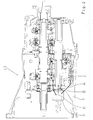
- FIG. 2 Subject of the FIG. 2 is an overview of a transmission 13, in which an inventive device for êtöölung a transmission shaft 1 integrated is.
- the leakage oil flow for internal lubrication of the transmission shaft 1 by arrow A the ⁇ lansaugstrom indicated by arrow B and the pressure oil flow to the oiling points of the transmission by arrow C.
Description
Die vorliegende Erfindung bezieht sich auf ein Verfahren zur Innenbeölung einer koaxial zur Ölpumpe eines Getriebes angeordneten und die Ölpumpe antreibenden Getriebewelle gemäß dem Oberbegriff des Patentanspruchs 1. Desweiteren bezieht sich die Erfindung auf eine Einrichtung zur Innenbeölung einer koaxial zur Ölpumpe eines Getriebes angeordneten und die Ölpumpe antreibenden Getriebewelle, insbesondere zur Durchführung des erfindungsgemäßen Verfahrens.The present invention relates to a method for internal lubrication of a coaxial with the oil pump of a transmission arranged and the oil pump driving gear shaft according to the preamble of
Zur Innenbeölung von Getriebewellen sind aus dem Stand der Technik unterschiedliche Verfahren und Einrichtungen bekannt. Beispielsweise kann die Innenbeölung von Getriebewellen durch passive Beölungssysteme erfolgen, bei denen spezielle Ölleiteinrichtungen verwendet werden, welche das Öl mittels Tropfkanten im Gehäuse oder Ölfangeinrichtungen sammeln und über Kanäle zu einem Ende der zu beölenden Getriebewelle leiten; das Öl wird mittels einer an dem einen Ende der zu beölenden Getriebewelle in die Welle hineinragenden Ölführung oder mittels einer Drehdurchführung in die Welle geleitet.For internal lubrication of gear shafts different methods and devices are known from the prior art. For example, the internal lubrication of transmission shafts can be done by passive lubrication systems, which use special Ölleiteinrichtungen which collect the oil by means of drip edges in the housing or Ölfangeinrichtungen and lead via channels to one end of the gear shaft to be oiled; the oil is passed into the shaft by means of a oil guide protruding into the shaft at one end of the gear shaft to be oiled or by means of a rotary feedthrough.
Aus der
Die bekannte Einrichtung umfasst zumindest zwei in der Fließrichtung des Öls angeordnete hohle Wellen, wobei eine Hauptwelle koaxial in einem Aufnahmebereich einer Antriebswelle angeordnet und in dieser über ein Wälzlager gelagert ist. Um Schmierstellen bei unterschiedlichen Ölförderwirkungsgraden und Drehzahlen der Wellen ausreichend mit schmierendem Öl versorgen zu können, ist gemäß der
In nachteiliger Weise werden bei derartigen Systemen zusätzliche Bauteile, wie beispielsweise Ölleiteinrichtungen und gegebenenfalls eine Drehdurchführung benötigt, was sich auf den Montageaufwand und die Herstellungs- und Wartungskosten negativ auswirkt.Disadvantageously, in such systems, additional components, such as, for example, oil-conducting devices and possibly a rotary feedthrough, are required, which has a negative effect on the assembly effort and the manufacturing and maintenance costs.
Ferner kann die Innenbeölung von Getriebewellen durch aktive Beölungssysteme gewährleistet werden. Hierbei wird das Öl durch eine Pumpe und ein Ölleitungssystem zu einer Einspritzdüse am Ende der zu beölenden Getriebewelle bzw. zu einer Drehdurchführung gepumpt und in die Welle eingespritzt. Auch bei aktiven Beölungssystemen sind in nachteiliger Weise zusätzliche Bauteile, wie z.B. Ölleiteinrichtungen, eine Einspritzdüse und eine Drehdurchführung erforderlich.Furthermore, the internal lubrication of transmission shafts can be ensured by active lubrication systems. Here, the oil is pumped by a pump and an oil line system to an injection nozzle at the end of the gear shaft to be oiled or to a rotary union and injected into the shaft. Also in active oiling systems, additional components such as e.g. Ölleiteinrichtungen, an injection nozzle and a rotary feedthrough required.
Beispielsweise ist aus der
Schließlich offenbart die
Der vorliegenden Erfindung liegt die Aufgabe zugrunde, ein Verfahren zur Innenbeölung einer koaxial zur Ölpumpe eines Getriebes angeordneten und die Ölpumpe antreibenden Getriebewelle anzugeben, durch dessen Durchführung weniger zusätzliche Bauteile benötigt werden, als bei den aus dem Stand der Technik bekannten Verfahren. Ein weiteres Ziel der Erfindung ist es, eine Einrichtung zur Innenbeölung einer koaxial zur Ölpumpe eines Getriebes angeordneten und die Öl-pumpe antreibenden Getriebewelle, insbesondere zur Durchführung des erfindungsgemä ßen Verfahrens anzugeben, welche eine geringe Anzahl von zusätzlichen Bauteilen aufweist und eine effektive Innenbeölung gewährleistet.The present invention has for its object to provide a method for internal lubrication of a coaxial with the oil pump of a transmission arranged and drive the oil pump drive shaft, through its implementation less additional components are required, as in the known from the prior art method. Another object of the invention is to provide a device for internal lubrication of a coaxial with the oil pump of a transmission and the oil pump driving gear shaft, in particular for carrying out the inventive specify method, which has a small number of additional components and ensures an effective internal lubrication.
Diese Aufgabe wird für ein Verfahren zur Innenbeölung einer Getriebewelle durch die Merkmale des Patentanspruchs 1 gelöst. Eine Einrichtung zur Innenbeölung einer Getriebewelle, insbesondere zur Durchführung des erfindungsgemäßen Verfahrens ist Gegenstand der unabhängigen Patentansprüche 6 und 10. Weitere erfindungsgemäße Ausgestaltungen und Vorteile gehen aus den entsprechenden Unteransprüchen hervor.This object is achieved for a method for internal lubrication of a transmission shaft by the features of
Demnach wird ein Verfahren zur Innenbeölung einer koaxial zur Ölpumpe eines Getriebes angeordneten und die Ölpumpe antreibenden Getriebewelle vorgeschlagen, im Rahmen dessen die Innenbeölung durch das Leckageöl der in das Getriebe integrierten Ölpumpe erfolgt.Accordingly, a method for internal lubrication of a coaxial with the oil pump of a transmission arranged and the oil pump driving transmission shaft is proposed, in the context of which the internal lubrication is carried out by the leakage oil of the oil pump integrated in the transmission.
Die in das Getriebe integrierte Ölpumpe wird durch die zu beölende Getriebewelle angetrieben und ist koaxial zu dieser angeordnet und vorzugsweise an die Kupplungsglocke angeflanscht. Gemäß der Erfindung wird das Leckageöl zumindest einer Pumpenwellenlagerstelle in die als Hohlwelle ausgeführte Pumpenwelle geleitet.The integrated in the transmission oil pump is driven by the gear shaft to be oiled and is arranged coaxially to this and preferably flanged to the clutch bell. According to the invention, the leakage oil is passed at least one pump shaft bearing point in the executed as a hollow shaft pump shaft.
Wenn die Beölung der Pumpenwellenlagerstellen nicht ausreichend ist, kann diese durch geeignete Maßnahmen verbessert werden. Zu diesem Zweck können gemäß der Erfindung die Lagerstellen der Pumpenwelle durch je eine Nut im Pumpengehäuse oder im Pumpendeckel mit der Druckseite der Pumpe verbunden sein.If the lubrication of the pump shaft bearings is insufficient, this can be improved by appropriate measures. For this purpose, according to the invention, the bearing points of the pump shaft may be connected by a respective groove in the pump housing or in the pump cover with the pressure side of the pump.
Das Öl wird in die zu beölende Getriebewelle über einen Mitnehmer weitergeleitet, welcher eine Innenbohrung aufweist und die Pumpenwelle mit der zu beölenden Getriebewelle kraftschlüssig verbindet. Für den Fall, dass die Leckageölmenge für die Innenbeölung der zu beölenden Getriebewelle nicht ausreicht, wird gemäß einer Weiterbildung der Erfindung die Leckageölmenge durch geeignete Maßnahmen an zumindest einer Pumpenwellenlagerstelle gezielt vergrößert.The oil is forwarded in the gear shaft to be oiled via a driver, which has an inner bore and connects the pump shaft with the gear shaft to be oiled frictionally. In the event that the amount of leakage oil for internal lubrication of the gear shaft to be oiled is insufficient, the leakage oil quantity is selectively increased by suitable measures on at least one pump shaft bearing point according to an embodiment of the invention.
Beispielsweise kann für den Fall, dass die Pumpenwellenlagerung als Gleitlagerung ausgeführt ist, die Leckageölmenge durch Einbringen einer axialen Nut in zumindest eine Pumpenwellenlagerstelle im Pumpengehäuse vergrößert werden. In vorteilhafter Weise kann das Leckageöl einer weiteren Lagerstelle der Pumpenwelle sowie auftretende Leckageölstromverluste zwischen der Pumpenwelle und dem Mitnehmer durch geeignete Maßnahmen zur Beölung weiterer Komponenten des Getriebes, beispielsweise von Lagern, verwendet werden.For example, in the event that the pump shaft bearing is designed as a sliding bearing, the amount of leakage oil can be increased by introducing an axial groove into at least one pump shaft bearing point in the pump housing. Advantageously, the leakage oil of a further bearing point of the pump shaft and occurring leakage oil flow losses between the pump shaft and the driver by suitable measures for lubrication of other components of the transmission, such as bearings, are used.
Die erfindungsgemäße Einrichtung zur Innenbeölung einer koaxial zur Ölpumpe eines Getriebes angeordneten und die Ölpumpe antreibenden Getriebewelle weist gemäß der Erfindung Mittel auf, über die das Leckageöl zumindest einer Pumpenwellenlagerstelle an die zu beölende Getriebewelle weitergeleitet wird. Wie bereits erläutert, sind als Mittel zur Weiterleitung des Leckageöls an die zu beölende Getriebewelle, zum Einen die gemäß der Erfindung als Hohlwelle ausgeführte Pumpenwelle und zum Anderen der eine Innenbohrung aufweisende Mitnehmer vorgesehen; das Leckageöl zumindest einer Pumpenwellenlagerstelle ist in die als Hohlwelle ausgeführte Pumpenwelle leitbar und über die Innenbohrung des Mitnehmers an die zu beölende Getriebewelle weiterleitbar.The device according to the invention for internal lubrication of a coaxial with the oil pump of a transmission arranged and the oil pump driving gear shaft has, according to the invention means via which the leakage oil at least one pump shaft bearing point is forwarded to the gear shaft to be oiled. As already explained, are provided as a means for forwarding the leakage oil to the gear shaft to be oiled, on the one hand according to the invention designed as a hollow shaft pump shaft and on the other hand, an inner bore having driver; the leakage oil of at least one pump shaft bearing point can be conducted into the pump shaft designed as a hollow shaft and forwarded via the inner bore of the driver to the gear shaft to be oiled.
Die Einrichtung zur Innenbeölung einer Getriebewelle umfasst optional Mittel, durch die die Leckageölmenge der zumindest einen Pumpenwellenlagerstelle gezielt vergrößert wird, wobei für den Fall, dass die Pumpenwellenlagerung als Gleitlagerung ausgeführt ist, die Mittel eine axiale Nut in zumindest einer Pumpenwellenlagerstelle im Pumpengehäuse umfassen. Die Einrichtung kann derart aufgebaut sein, dass das Leckageöl einer weiteren Lagerstelle der Pumpenwelle sowie auftretende Leckageölstromverluste zwischen der Pumpenwelle und dem Mitnehmer zur Beölung weiterer Komponenten des Getriebes verwendbar sind.The device for internal lubrication of a transmission shaft optionally comprises means by which the amount of leakage oil of the at least one pump shaft bearing point is specifically increased, wherein in the event that the pump shaft bearing is designed as a sliding bearing, the means comprise an axial groove in at least one pump shaft bearing point in the pump housing. The device can be constructed in such a way that the leakage oil of a further bearing point of the pump shaft and occurring leakage oil flow losses between the pump shaft and the driver can be used for lubricating further components of the transmission.
Zur Verbesserung der Beölung der Pumpenwellenlagerung können die Lagerstellen der Pumpenwelle durch je eine sich radial erstreckende Nut im Pumpengehäuse oder im Pumpendeckel mit der Druckseite der Ölpumpe verbunden sein.To improve the lubrication of the pump shaft bearing, the bearing points of the pump shaft can be connected by a respective radially extending groove in the pump housing or in the pump cover with the pressure side of the oil pump.
Durch die erfindungsgemäße Konzeption wird die Sicherstellung der Beölung einer Getriebewelle bzw. der auf der Getriebewelle montierten Bauteile sowie der Wellenlagerung im Getriebe gewährleistet, wobei in vorteilhafter Weise das ohnehin vorhandene Leckageöl der in das Getriebe integrierten Ölpumpe verwendet wird.The concept of the invention ensures the lubrication of a gear shaft or the components mounted on the gear shaft and the shaft bearing in the transmission, wherein the already existing leakage oil of the oil pump integrated in the transmission is used in an advantageous manner.
Zudem entfallen die nach dem Stand der Technik erforderlichen Bauteile, da eine Einspritzdüse sowie Ölleitbleche, Ölführungen, und Drehdurchführungen für die Innenbeölung der Getriebewelle nicht benötigt werden, was in einer Reduzierung des Montageaufwands für die Einrichtung zur Innenbeölung und der Kosten resultiert; die Beölung wird im Gegensatz zu den aus dem Stand der Technik bekannten Systemen nicht mehr direkt über die Ölpumpe oder über ein bekanntes passives Beölungssystem realisiert.In addition, the prior art components are eliminated since an injector and oil guide plates, oil passages, and rotary joints for the internal lubrication of the transmission shaft are not required, which results in a reduction of the assembly costs for the internal lubrication and the cost; the oiling is not realized in contrast to the systems known from the prior art directly via the oil pump or a known passive oiling system.
Ferner steht durch die erfindungsgemäße Konzeption die volle Förderleistung der Ölpumpe und somit mehr Öl für die anderen Beölungsstellen des Getriebes zur Verfügung. Es ist auch möglich, die Ölpumpe kleiner zu dimensionieren, wodurch eine Wirkungsgradsteigerung erzielt wird.Furthermore, the concept of the invention, the full capacity of the oil pump and thus more oil for the other lubrication points of the transmission available. It is also possible to make the oil pump smaller, whereby an increase in efficiency is achieved.
Die Erfindung wird im Folgenden anhand der beigefügten Figuren beispielhaft näher erläutert. Es zeigen:
- Figur 1:
- Eine Schnittansicht eines Teils eines Getriebes zur Veranschaulichung der Bauteile einer erfindungsgemäßen Einrichtung zur Innenbeölung einer Getriebewelle; und
- Figur 2:
- Eine Übersichtsdarstellung eines Getriebes umfassend eine erfindungsgemäße Einrichtung zur Innenbeölung einer Getriebewelle.
- FIG. 1:
- A sectional view of a portion of a transmission to illustrate the components of a device according to the invention for Innenöölung a transmission shaft; and
- FIG. 2:
- An overview of a transmission comprising an inventive device for Innenöölung a transmission shaft.
Gemäß der Erfindung erfolgt die Innenbeölung einer Getriebewelle durch das ohnehin vorhandene Leckageöl der in das Getriebe integrierten Ölpumpe. Bezugnehmend auf
Erfindungsgemäß wird das Leckageöl zumindest einer Pumpenwellenlagerstelle 3 in die als Hohlwelle ausgeführte Pumpenwelle 4 geleitet und über einen eine Innenbohrung aufweisenden und die Pumpenwelle 4 mit der zu beölenden Getriebewelle 1 verbindenden Mitnehmer 5, an die zu beölende und ebenfalls eine Innenbohrung aufweisende Getriebewelle 1 weitergeleitet. Der Leckageölfluss zur Innenbeölung der Getriebewelle 1 ist in
Für den Fall, dass die Leckageölmenge der zumindest einen Pumpenwellenlagerstelle 3 für die Innenbeölung der zu beölenden Getriebewelle 1 nicht ausreicht, wird sie durch geeignete Maßnahmen an zumindest einer Lagerstelle der Pumpenwelle gezielt vergrößert.In the event that the amount of leakage oil of the at least one pump shaft bearing point 3 is insufficient for the internal lubrication of the
Bei dem in
In vorteilhafter Weise kann das Leckageöl einer zweiten Lagerstelle 6 der Pumpenwelle 4, veranschaulicht durch Pfeil D, sowie auftretende Leckageölstromverluste zwischen der Pumpenwelle 4 und dem Mitnehmer 5, veranschaulicht durch Pfeil E, zur Beölung weiterer Komponenten des Getriebes, verwendet werden.Advantageously, the leakage oil of a second bearing 6 of the
Ferner kann vorgesehen sein, dass die Beölung der Pumpenwellenlagerung dadurch verbessert wird, dass die Lagerstellen 3, 6 der Pumpenwelle 4 durch je eine sich radial erstreckende Nut 8, 9 im Pumpengehäuse oder im Pumpendeckel mit der Druckseite 11 der Ölpumpe 2 verbunden sind. In
Gegenstand der
- 11
- Getriebewellegear shaft
- 22
- Ölpumpeoil pump
- 33
- PumpenwellenlagerstellePump shaft bearing
- 44
- Pumpenwellepump shaft
- 55
- Mitnehmertakeaway
- 66
- PumpenwellenlagerstellePump shaft bearing
- 77
- KupplungsglockeKupplungsglocke
- 88th
- Nutgroove
- 99
- Nutgroove
- 1010
- Nutgroove
- 1111
-
Druckseite der Ölpumpe 2Pressure side of the
oil pump 2 - 1212
-
Saugseite der Ölpumpe 2Suction side of the
oil pump 2 - 1313
- Getriebetransmission
- AA
-
Leckageölfluss zur Innenbeölung der Getriebewelle 1Leakage oil flow for internal lubrication of the
gear shaft 1 - BB
- ÖlansaugstromÖlansaugstrom
- CC
- DruckölstromPressure oil flow
- DD
-
Leckageöl der zweiten Lagerstelle 6Leakage oil of the
second bearing 6 - Ee
-
Leckageölstromverluste zwischen der Pumpenwelle 4 und dem Mitnehmer 5Leakage oil flow losses between the
pump shaft 4 and thedriver 5
Claims (10)
- Method for internal lubrication of a transmission shaft (1) which is arranged coaxially with respect to the oil pump (2) of a transmission (13) and drives the oil pump (2), the internal lubrication of the transmission shaft (1) taking place by way of the leakage oil, which is present in any case, of the oil pump (2) which is integrated into the transmission (13), characterized in that the leakage oil of at least one pump shaft bearing point (3) is guided into the pump shaft (4) which is configured as a hollow shaft, and is guided further to the transmission shaft (1) to be lubricated via a tappet (5) which has an internal bore and connects the pump shaft (4) to the transmission shaft (1) to be lubricated.
- Method for internal lubrication of a transmission shaft (1), according to Claim 1, characterized in that the leakage oil quantity of the at least one pump shaft bearing point (3) is increased in a targeted manner for the case where the leakage oil quantity of the at least one pump shaft bearing point (3) is not sufficient for the internal lubrication of the transmission shaft (1) to be lubricated.
- Method for internal lubrication of a transmission shaft (1), according to Claim 2, characterized in that, for the case where the pump shaft bearing is configured as a plain bearing, the leakage oil quantity is increased by way of the introduction of an axial groove (10) into at least one pump shaft bearing point (3) in the pump housing.
- Method for internal lubrication of a transmission shaft (1), according to Claim 1, 2 or 3, characterized in that the leakage oil of a further bearing point (6) of the pump shaft (4) and leakage oil flow losses which occur between the pump shaft (4) and the tappet (5) are used for lubricating further components of the transmission (13).
- Method for internal lubrication of a transmission shaft (1), according to Claim 1, 2, 3 or 4, characterized in that the lubrication of the pump shaft bearing is improved by virtue of the fact that the bearing points (3, 6) of the pump shaft (4) are connected to the pressure side (11) of the oil pump (2) by way of in each case one radially extending groove (8, 9) in the pump housing or in the pump cover.
- Device for internal lubrication of a transmission shaft (1) which is arranged coaxially with respect to the oil pump (2) of a transmission (13) and drives the oil pump (2), the said device having means, via which the leakage oil of at least one pump shaft bearing point (3) is guided further to the transmission shaft (1) to be lubricated, characterized in that the means for guiding the leakage oil further to the transmission shaft (1) to be lubricated comprise the pump shaft (4) which is configured as a hollow shaft and a tappet (5) which has an internal bore and connects the pump shaft (4) to the transmission shaft (1) to be lubricated, in such a way that the leakage oil of at least one pump shaft bearing point (3) can be guided into the pump shaft (4) which is configured as a hollow shaft, and can be guided further via the internal bore of the tappet (5) to the transmission shaft (1) to be lubricated.
- Device for internal lubrication of a transmission shaft (1), according to Claim 6, characterized in that means (10) are provided, by way of which the leakage oil quantity of the at least one pump shaft bearing point (3) is increased in a targeted manner.
- Device for internal lubrication of a transmission shaft (1), according to Claim 7, characterized in that, for the case where the pump shaft bearing is configured as a plain bearing, the means (10) comprise an axial groove (10) into at least one pump shaft bearing point (3) in the pump housing.
- Device for internal lubrication of the transmission shaft (1), according to one of Claims 6 to 8, characterized in that the leakage oil of a further bearing point (6) of the pump shaft (4) and leakage oil flow losses which occur between the pump shaft (4) and the tappet (5) can be used for lubricating further components of the transmission (13).
- Device for internal lubrication of a transmission shaft (1), according to the precharacterizing clause of Claim 6 or according to one of Claims 6 to 9, characterized in that, in order to improve the lubrication of the pump shaft bearing, the bearing points (3, 6) of the pump shaft (4) are connected to the pressure side (11) of the oil pump (2) by way of in each case one radially extending groove (8, 9) in the pump housing or in the pump cover.
Applications Claiming Priority (2)
| Application Number | Priority Date | Filing Date | Title |
|---|---|---|---|
| DE102010021894.4A DE102010021894B4 (en) | 2010-05-28 | 2010-05-28 | Method and device for Innenbeölung a coaxial with the oil pump of a transmission arranged and the oil pump driving gear shaft |
| PCT/EP2011/055163 WO2011147615A1 (en) | 2010-05-28 | 2011-04-04 | Method and device for the internal oiling of a gear shaft that is arranged coaxially to the oil pump of a gearbox and drives the oil pump |
Publications (2)
| Publication Number | Publication Date |
|---|---|
| EP2577112A1 EP2577112A1 (en) | 2013-04-10 |
| EP2577112B1 true EP2577112B1 (en) | 2015-11-04 |
Family
ID=44210348
Family Applications (1)
| Application Number | Title | Priority Date | Filing Date |
|---|---|---|---|
| EP11714013.7A Not-in-force EP2577112B1 (en) | 2010-05-28 | 2011-04-04 | Method and device for the internal oiling of a gear shaft that is arranged coaxially to the oil pump of a gearbox and drives the oil pump |
Country Status (5)
| Country | Link |
|---|---|
| US (1) | US9188216B2 (en) |
| EP (1) | EP2577112B1 (en) |
| CN (1) | CN102859237B (en) |
| DE (1) | DE102010021894B4 (en) |
| WO (1) | WO2011147615A1 (en) |
Families Citing this family (6)
| Publication number | Priority date | Publication date | Assignee | Title |
|---|---|---|---|---|
| CN102777478A (en) * | 2012-07-13 | 2012-11-14 | 无锡市聚英机械制造有限公司 | Hollow shaft for reducer |
| WO2014133669A1 (en) * | 2013-02-26 | 2014-09-04 | United Technologies Corporation | Lubrication of journal bearing during clockwise and counter-clockwise rotation |
| DE102015205986A1 (en) * | 2015-04-02 | 2016-10-06 | Zf Friedrichshafen Ag | Transfer case assembly |
| DE102016213611B4 (en) | 2016-07-25 | 2022-12-01 | Zf Friedrichshafen Ag | Rotor pump and arrangement for driving a rotor pump |
| CN109237009A (en) * | 2018-11-05 | 2019-01-18 | 绿传(北京)科技有限公司 | A kind of automatic transmission with external double oil pumps |
| CN109340367A (en) * | 2018-11-05 | 2019-02-15 | 绿传(北京)科技有限公司 | A kind of external oil pump for speed changer |
Citations (3)
| Publication number | Priority date | Publication date | Assignee | Title |
|---|---|---|---|---|
| DE3939651C1 (en) * | 1989-11-30 | 1991-05-08 | Mercedes-Benz Aktiengesellschaft, 7000 Stuttgart, De | |
| EP0985852A2 (en) * | 1998-09-08 | 2000-03-15 | General Motors Corporation | Torque converter and seal arrangement |
| US20080191422A1 (en) * | 2007-02-12 | 2008-08-14 | Norman Schoenek | Transmission pump seal |
Family Cites Families (26)
| Publication number | Priority date | Publication date | Assignee | Title |
|---|---|---|---|---|
| US3065822A (en) * | 1960-12-12 | 1962-11-27 | Int Harvester Co | Lubricating means for a power transmission |
| BE756886A (en) * | 1970-01-02 | 1971-03-01 | Gen Electric | DOSING AND EVACUATION PUMP |
| US3889489A (en) * | 1974-08-23 | 1975-06-17 | Gen Motors Corp | Lubricated spline coupling |
| US4458318A (en) * | 1981-04-24 | 1984-07-03 | Borg-Warner Corporation | Control arrangement for a variable pulley transmission |
| US4494943A (en) * | 1981-09-08 | 1985-01-22 | Nippondenso Co., Ltd. | Power transmission device for vehicles |
| US4669999A (en) * | 1984-08-22 | 1987-06-02 | Sundstrand Corporation | Lubricant delivering and containment overload shearable coupling |
| AT389739B (en) * | 1984-09-21 | 1990-01-25 | Avl Verbrennungskraft Messtech | FOUR-STROKE COMBUSTION ENGINE WITH A LUBRICATED OIL PUMP DESIGNED AS A GEAR PUMP |
| US4784630A (en) * | 1986-12-17 | 1988-11-15 | Fuji Jukogyo Kabushiki Kaisha | Rotating speed detecting device for a continuously variable transmission for a vehicle |
| US4789316A (en) * | 1986-12-29 | 1988-12-06 | Ingersoll-Rand Company | Gear lubrication pump for an air motor |
| US4747808A (en) * | 1987-01-08 | 1988-05-31 | Ford Motor Company | System for actuating the displaceable pulley in a continually variable transmission |
| DE3905770A1 (en) | 1988-03-02 | 1989-09-14 | Zahnradfabrik Friedrichshafen | Method and apparatus for cleaning lubricating oil in a gearing |
| JP3223215B2 (en) * | 1993-07-22 | 2001-10-29 | 本田技研工業株式会社 | Gear transmission |
| JP3097439B2 (en) * | 1994-03-17 | 2000-10-10 | 日産自動車株式会社 | Oil passage structure for continuously variable transmission |
| US5474152A (en) * | 1995-04-12 | 1995-12-12 | Teledyne Industries, Inc. | Lubrication system for a starter clutch assembly |
| JPH10318357A (en) * | 1997-05-16 | 1998-12-04 | Jatco Corp | Lubricating structure for transmission |
| JPH1151161A (en) * | 1997-07-31 | 1999-02-23 | Aichi Mach Ind Co Ltd | Lubricating structure of bearing for transmission |
| JP2002098171A (en) * | 2000-09-21 | 2002-04-05 | Jatco Transtechnology Ltd | Lubrication control device of starting clutch for automatic transmission |
| DE102004018226B4 (en) * | 2004-04-15 | 2011-07-28 | ZF Friedrichshafen AG, 88046 | Device for oil supply of shafts, which identify an axially extending bore or oil passage |
| JP4350692B2 (en) * | 2005-09-21 | 2009-10-21 | ジヤトコ株式会社 | Automatic transmission |
| DE102005052450A1 (en) * | 2005-11-03 | 2007-06-14 | Zf Friedrichshafen Ag | Units oiling device for use in automatic gear of motor vehicle, has oil holding tank whose interior is connected by radial bore with axial bore, where component regulating oil passage is arranged in end, of drive shaft |
| JP4688769B2 (en) * | 2006-09-27 | 2011-05-25 | 本田技研工業株式会社 | Oil pump unit for internal combustion engine |
| US8312858B2 (en) * | 2006-12-22 | 2012-11-20 | Kohler Co. | System and method for lubricating power transmitting elements |
| WO2009107797A1 (en) * | 2008-02-28 | 2009-09-03 | ダイキン工業株式会社 | Compressor |
| JP4616376B2 (en) * | 2008-09-04 | 2011-01-19 | ジヤトコ株式会社 | Support structure of cylindrical member in automatic transmission |
| JP5206457B2 (en) * | 2009-02-03 | 2013-06-12 | コベルコ建機株式会社 | Shaft lubrication device for hybrid work machines |
| CN102362100B (en) * | 2009-09-25 | 2014-04-16 | 爱信艾达株式会社 | Drive device |
-
2010
- 2010-05-28 DE DE102010021894.4A patent/DE102010021894B4/en not_active Expired - Fee Related
-
2011
- 2011-04-04 EP EP11714013.7A patent/EP2577112B1/en not_active Not-in-force
- 2011-04-04 WO PCT/EP2011/055163 patent/WO2011147615A1/en active Application Filing
- 2011-04-04 CN CN201180020075.0A patent/CN102859237B/en not_active Expired - Fee Related
- 2011-04-04 US US13/700,165 patent/US9188216B2/en not_active Expired - Fee Related
Patent Citations (3)
| Publication number | Priority date | Publication date | Assignee | Title |
|---|---|---|---|---|
| DE3939651C1 (en) * | 1989-11-30 | 1991-05-08 | Mercedes-Benz Aktiengesellschaft, 7000 Stuttgart, De | |
| EP0985852A2 (en) * | 1998-09-08 | 2000-03-15 | General Motors Corporation | Torque converter and seal arrangement |
| US20080191422A1 (en) * | 2007-02-12 | 2008-08-14 | Norman Schoenek | Transmission pump seal |
Also Published As
| Publication number | Publication date |
|---|---|
| EP2577112A1 (en) | 2013-04-10 |
| US9188216B2 (en) | 2015-11-17 |
| WO2011147615A1 (en) | 2011-12-01 |
| DE102010021894B4 (en) | 2015-07-09 |
| US20130233650A1 (en) | 2013-09-12 |
| CN102859237A (en) | 2013-01-02 |
| DE102010021894A1 (en) | 2011-12-01 |
| CN102859237B (en) | 2016-03-02 |
Similar Documents
| Publication | Publication Date | Title |
|---|---|---|
| EP2577112B1 (en) | Method and device for the internal oiling of a gear shaft that is arranged coaxially to the oil pump of a gearbox and drives the oil pump | |
| DE112009002476T5 (en) | Infeed system for differential gear lubricant in a drive axle assembly | |
| DE102015218280A1 (en) | Bearing lubrication for electrical machine | |
| DE102016114403B4 (en) | PTO SYSTEM FOR AN AUTOMOTIVE VEHICLE PROVIDING OIL DRAIN AND COMPRESSION OIL TO THE RELEASE CLUTCH | |
| DE102018203696A1 (en) | System with a lubricating oil circuit and with a cooling oil circuit | |
| DE102019201586A1 (en) | Oil container for cooling and / or lubricating bearings of a drive train of a vehicle, in particular a motor vehicle | |
| DE102012222795A1 (en) | Motor vehicle with a drive motor and a device for generating a negative pressure for a servo consumer | |
| DE102014210774B4 (en) | Hydraulic drive with an adjustable hydraulic axial piston machine in dry-case design | |
| DE102005052451A1 (en) | Controlling device for volume flow rate in internal oiled shaft of transmission system, has outlet bore which corresponds with radial bore of internal oiled shaft such that oil can reach to oiled components outside internal oiled shaft | |
| EP1600666B1 (en) | Hydromechanical driving device for a vehicle | |
| DE102021200276A1 (en) | Device for cooling and lubricating components of a vehicle and drive device with such a device | |
| DE102012010181A1 (en) | Motor vehicle drive train has drive unit and gear, where gear has gear oil for cooling and lubricating gear components, and gear is surrounded by gear housing | |
| DE102013224499A1 (en) | Optimized gear arrangement | |
| DE112013005092B4 (en) | Clutch lubrication | |
| EP3532747A1 (en) | Drive train, in particular hybrid drive train for a motor vehicle | |
| DE102020120419A1 (en) | Oil supply device for a transmission section and transmission section with the oil supply device | |
| DE102021200278A1 (en) | Device for cooling and lubricating components of a vehicle and drive device with such a device | |
| DE202010007319U1 (en) | Device for internal lubrication of a coaxial with the oil pump of a transmission arranged and the oil pump driving gear shaft | |
| WO2006122687A1 (en) | Device for lubricating the components of a motor vehicle | |
| EP1644617A1 (en) | Cover plate for a crankcase | |
| EP3532748A1 (en) | Drive train, in particular hybrid drive train for a motor vehicle | |
| DE102018218946A1 (en) | Partial covering of a drive unit by means of a thin-walled shielding element, the ends of which are fixed in a gearbox housing | |
| DE202008010126U1 (en) | Oil pump of an automated motor vehicle transmission | |
| EP4015877A1 (en) | E-axis transmission, suitable for forward and reverse travel | |
| DE102020208812A1 (en) | transmission |
Legal Events
| Date | Code | Title | Description |
|---|---|---|---|
| PUAI | Public reference made under article 153(3) epc to a published international application that has entered the european phase |
Free format text: ORIGINAL CODE: 0009012 |
|
| 17P | Request for examination filed |
Effective date: 20121002 |
|
| AK | Designated contracting states |
Kind code of ref document: A1 Designated state(s): AL AT BE BG CH CY CZ DE DK EE ES FI FR GB GR HR HU IE IS IT LI LT LU LV MC MK MT NL NO PL PT RO RS SE SI SK SM TR |
|
| DAX | Request for extension of the european patent (deleted) | ||
| 17Q | First examination report despatched |
Effective date: 20140704 |
|
| GRAP | Despatch of communication of intention to grant a patent |
Free format text: ORIGINAL CODE: EPIDOSNIGR1 |
|
| INTG | Intention to grant announced |
Effective date: 20150618 |
|
| GRAS | Grant fee paid |
Free format text: ORIGINAL CODE: EPIDOSNIGR3 |
|
| GRAA | (expected) grant |
Free format text: ORIGINAL CODE: 0009210 |
|
| AK | Designated contracting states |
Kind code of ref document: B1 Designated state(s): AL AT BE BG CH CY CZ DE DK EE ES FI FR GB GR HR HU IE IS IT LI LT LU LV MC MK MT NL NO PL PT RO RS SE SI SK SM TR |
|
| REG | Reference to a national code |
Ref country code: GB Ref legal event code: FG4D Free format text: NOT ENGLISH |
|
| REG | Reference to a national code |
Ref country code: CH Ref legal event code: EP |
|
| REG | Reference to a national code |
Ref country code: AT Ref legal event code: REF Ref document number: 759436 Country of ref document: AT Kind code of ref document: T Effective date: 20151115 |
|
| REG | Reference to a national code |
Ref country code: IE Ref legal event code: FG4D Free format text: LANGUAGE OF EP DOCUMENT: GERMAN |
|
| REG | Reference to a national code |
Ref country code: DE Ref legal event code: R096 Ref document number: 502011008273 Country of ref document: DE |
|
| REG | Reference to a national code |
Ref country code: NL Ref legal event code: MP Effective date: 20151104 |
|
| REG | Reference to a national code |
Ref country code: LT Ref legal event code: MG4D |
|
| PG25 | Lapsed in a contracting state [announced via postgrant information from national office to epo] |
Ref country code: IT Free format text: LAPSE BECAUSE OF FAILURE TO SUBMIT A TRANSLATION OF THE DESCRIPTION OR TO PAY THE FEE WITHIN THE PRESCRIBED TIME-LIMIT Effective date: 20151104 Ref country code: NO Free format text: LAPSE BECAUSE OF FAILURE TO SUBMIT A TRANSLATION OF THE DESCRIPTION OR TO PAY THE FEE WITHIN THE PRESCRIBED TIME-LIMIT Effective date: 20160204 Ref country code: LT Free format text: LAPSE BECAUSE OF FAILURE TO SUBMIT A TRANSLATION OF THE DESCRIPTION OR TO PAY THE FEE WITHIN THE PRESCRIBED TIME-LIMIT Effective date: 20151104 Ref country code: IS Free format text: LAPSE BECAUSE OF FAILURE TO SUBMIT A TRANSLATION OF THE DESCRIPTION OR TO PAY THE FEE WITHIN THE PRESCRIBED TIME-LIMIT Effective date: 20160304 Ref country code: NL Free format text: LAPSE BECAUSE OF FAILURE TO SUBMIT A TRANSLATION OF THE DESCRIPTION OR TO PAY THE FEE WITHIN THE PRESCRIBED TIME-LIMIT Effective date: 20151104 Ref country code: ES Free format text: LAPSE BECAUSE OF FAILURE TO SUBMIT A TRANSLATION OF THE DESCRIPTION OR TO PAY THE FEE WITHIN THE PRESCRIBED TIME-LIMIT Effective date: 20151104 Ref country code: HR Free format text: LAPSE BECAUSE OF FAILURE TO SUBMIT A TRANSLATION OF THE DESCRIPTION OR TO PAY THE FEE WITHIN THE PRESCRIBED TIME-LIMIT Effective date: 20151104 |
|
| PG25 | Lapsed in a contracting state [announced via postgrant information from national office to epo] |
Ref country code: LV Free format text: LAPSE BECAUSE OF FAILURE TO SUBMIT A TRANSLATION OF THE DESCRIPTION OR TO PAY THE FEE WITHIN THE PRESCRIBED TIME-LIMIT Effective date: 20151104 Ref country code: PT Free format text: LAPSE BECAUSE OF FAILURE TO SUBMIT A TRANSLATION OF THE DESCRIPTION OR TO PAY THE FEE WITHIN THE PRESCRIBED TIME-LIMIT Effective date: 20160304 Ref country code: RS Free format text: LAPSE BECAUSE OF FAILURE TO SUBMIT A TRANSLATION OF THE DESCRIPTION OR TO PAY THE FEE WITHIN THE PRESCRIBED TIME-LIMIT Effective date: 20151104 Ref country code: SE Free format text: LAPSE BECAUSE OF FAILURE TO SUBMIT A TRANSLATION OF THE DESCRIPTION OR TO PAY THE FEE WITHIN THE PRESCRIBED TIME-LIMIT Effective date: 20151104 Ref country code: PL Free format text: LAPSE BECAUSE OF FAILURE TO SUBMIT A TRANSLATION OF THE DESCRIPTION OR TO PAY THE FEE WITHIN THE PRESCRIBED TIME-LIMIT Effective date: 20151104 Ref country code: GR Free format text: LAPSE BECAUSE OF FAILURE TO SUBMIT A TRANSLATION OF THE DESCRIPTION OR TO PAY THE FEE WITHIN THE PRESCRIBED TIME-LIMIT Effective date: 20160205 Ref country code: FI Free format text: LAPSE BECAUSE OF FAILURE TO SUBMIT A TRANSLATION OF THE DESCRIPTION OR TO PAY THE FEE WITHIN THE PRESCRIBED TIME-LIMIT Effective date: 20151104 |
|
| PG25 | Lapsed in a contracting state [announced via postgrant information from national office to epo] |
Ref country code: CZ Free format text: LAPSE BECAUSE OF FAILURE TO SUBMIT A TRANSLATION OF THE DESCRIPTION OR TO PAY THE FEE WITHIN THE PRESCRIBED TIME-LIMIT Effective date: 20151104 |
|
| REG | Reference to a national code |
Ref country code: DE Ref legal event code: R097 Ref document number: 502011008273 Country of ref document: DE |
|
| PG25 | Lapsed in a contracting state [announced via postgrant information from national office to epo] |
Ref country code: DK Free format text: LAPSE BECAUSE OF FAILURE TO SUBMIT A TRANSLATION OF THE DESCRIPTION OR TO PAY THE FEE WITHIN THE PRESCRIBED TIME-LIMIT Effective date: 20151104 Ref country code: SK Free format text: LAPSE BECAUSE OF FAILURE TO SUBMIT A TRANSLATION OF THE DESCRIPTION OR TO PAY THE FEE WITHIN THE PRESCRIBED TIME-LIMIT Effective date: 20151104 Ref country code: RO Free format text: LAPSE BECAUSE OF FAILURE TO SUBMIT A TRANSLATION OF THE DESCRIPTION OR TO PAY THE FEE WITHIN THE PRESCRIBED TIME-LIMIT Effective date: 20151104 Ref country code: EE Free format text: LAPSE BECAUSE OF FAILURE TO SUBMIT A TRANSLATION OF THE DESCRIPTION OR TO PAY THE FEE WITHIN THE PRESCRIBED TIME-LIMIT Effective date: 20151104 Ref country code: SM Free format text: LAPSE BECAUSE OF FAILURE TO SUBMIT A TRANSLATION OF THE DESCRIPTION OR TO PAY THE FEE WITHIN THE PRESCRIBED TIME-LIMIT Effective date: 20151104 Ref country code: BE Free format text: LAPSE BECAUSE OF NON-PAYMENT OF DUE FEES Effective date: 20160430 |
|
| PLBE | No opposition filed within time limit |
Free format text: ORIGINAL CODE: 0009261 |
|
| STAA | Information on the status of an ep patent application or granted ep patent |
Free format text: STATUS: NO OPPOSITION FILED WITHIN TIME LIMIT |
|
| 26N | No opposition filed |
Effective date: 20160805 |
|
| PG25 | Lapsed in a contracting state [announced via postgrant information from national office to epo] |
Ref country code: SI Free format text: LAPSE BECAUSE OF FAILURE TO SUBMIT A TRANSLATION OF THE DESCRIPTION OR TO PAY THE FEE WITHIN THE PRESCRIBED TIME-LIMIT Effective date: 20151104 |
|
| REG | Reference to a national code |
Ref country code: CH Ref legal event code: PL |
|
| GBPC | Gb: european patent ceased through non-payment of renewal fee |
Effective date: 20160404 |
|
| PG25 | Lapsed in a contracting state [announced via postgrant information from national office to epo] |
Ref country code: LU Free format text: LAPSE BECAUSE OF FAILURE TO SUBMIT A TRANSLATION OF THE DESCRIPTION OR TO PAY THE FEE WITHIN THE PRESCRIBED TIME-LIMIT Effective date: 20160404 |
|
| REG | Reference to a national code |
Ref country code: IE Ref legal event code: MM4A |
|
| REG | Reference to a national code |
Ref country code: FR Ref legal event code: ST Effective date: 20161230 |
|
| PG25 | Lapsed in a contracting state [announced via postgrant information from national office to epo] |
Ref country code: LI Free format text: LAPSE BECAUSE OF NON-PAYMENT OF DUE FEES Effective date: 20160430 Ref country code: GB Free format text: LAPSE BECAUSE OF NON-PAYMENT OF DUE FEES Effective date: 20160404 Ref country code: CH Free format text: LAPSE BECAUSE OF NON-PAYMENT OF DUE FEES Effective date: 20160430 Ref country code: FR Free format text: LAPSE BECAUSE OF NON-PAYMENT OF DUE FEES Effective date: 20160502 |
|
| PG25 | Lapsed in a contracting state [announced via postgrant information from national office to epo] |
Ref country code: IE Free format text: LAPSE BECAUSE OF NON-PAYMENT OF DUE FEES Effective date: 20160404 |
|
| REG | Reference to a national code |
Ref country code: AT Ref legal event code: MM01 Ref document number: 759436 Country of ref document: AT Kind code of ref document: T Effective date: 20160404 |
|
| PG25 | Lapsed in a contracting state [announced via postgrant information from national office to epo] |
Ref country code: AT Free format text: LAPSE BECAUSE OF NON-PAYMENT OF DUE FEES Effective date: 20160404 |
|
| PG25 | Lapsed in a contracting state [announced via postgrant information from national office to epo] |
Ref country code: CY Free format text: LAPSE BECAUSE OF FAILURE TO SUBMIT A TRANSLATION OF THE DESCRIPTION OR TO PAY THE FEE WITHIN THE PRESCRIBED TIME-LIMIT Effective date: 20151104 Ref country code: HU Free format text: LAPSE BECAUSE OF FAILURE TO SUBMIT A TRANSLATION OF THE DESCRIPTION OR TO PAY THE FEE WITHIN THE PRESCRIBED TIME-LIMIT; INVALID AB INITIO Effective date: 20110404 |
|
| PG25 | Lapsed in a contracting state [announced via postgrant information from national office to epo] |
Ref country code: MC Free format text: LAPSE BECAUSE OF FAILURE TO SUBMIT A TRANSLATION OF THE DESCRIPTION OR TO PAY THE FEE WITHIN THE PRESCRIBED TIME-LIMIT Effective date: 20151104 Ref country code: MT Free format text: LAPSE BECAUSE OF FAILURE TO SUBMIT A TRANSLATION OF THE DESCRIPTION OR TO PAY THE FEE WITHIN THE PRESCRIBED TIME-LIMIT Effective date: 20151104 Ref country code: MK Free format text: LAPSE BECAUSE OF FAILURE TO SUBMIT A TRANSLATION OF THE DESCRIPTION OR TO PAY THE FEE WITHIN THE PRESCRIBED TIME-LIMIT Effective date: 20151104 Ref country code: TR Free format text: LAPSE BECAUSE OF FAILURE TO SUBMIT A TRANSLATION OF THE DESCRIPTION OR TO PAY THE FEE WITHIN THE PRESCRIBED TIME-LIMIT Effective date: 20151104 |
|
| PG25 | Lapsed in a contracting state [announced via postgrant information from national office to epo] |
Ref country code: BG Free format text: LAPSE BECAUSE OF FAILURE TO SUBMIT A TRANSLATION OF THE DESCRIPTION OR TO PAY THE FEE WITHIN THE PRESCRIBED TIME-LIMIT Effective date: 20151104 |
|
| PG25 | Lapsed in a contracting state [announced via postgrant information from national office to epo] |
Ref country code: AL Free format text: LAPSE BECAUSE OF FAILURE TO SUBMIT A TRANSLATION OF THE DESCRIPTION OR TO PAY THE FEE WITHIN THE PRESCRIBED TIME-LIMIT Effective date: 20151104 |
|
| PGFP | Annual fee paid to national office [announced via postgrant information from national office to epo] |
Ref country code: DE Payment date: 20220302 Year of fee payment: 12 |
|
| REG | Reference to a national code |
Ref country code: DE Ref legal event code: R119 Ref document number: 502011008273 Country of ref document: DE |
|
| PG25 | Lapsed in a contracting state [announced via postgrant information from national office to epo] |
Ref country code: DE Free format text: LAPSE BECAUSE OF NON-PAYMENT OF DUE FEES Effective date: 20231103 |