EP2576156B1 - Methods and systems for inspection sensor placement - Google Patents
Methods and systems for inspection sensor placement Download PDFInfo
- Publication number
- EP2576156B1 EP2576156B1 EP11716337.8A EP11716337A EP2576156B1 EP 2576156 B1 EP2576156 B1 EP 2576156B1 EP 11716337 A EP11716337 A EP 11716337A EP 2576156 B1 EP2576156 B1 EP 2576156B1
- Authority
- EP
- European Patent Office
- Prior art keywords
- sensor
- remote sensor
- target object
- accordance
- virtual representation
- Prior art date
- Legal status (The legal status is an assumption and is not a legal conclusion. Google has not performed a legal analysis and makes no representation as to the accuracy of the status listed.)
- Active
Links
Images


Classifications
-
- B—PERFORMING OPERATIONS; TRANSPORTING
- B25—HAND TOOLS; PORTABLE POWER-DRIVEN TOOLS; MANIPULATORS
- B25J—MANIPULATORS; CHAMBERS PROVIDED WITH MANIPULATION DEVICES
- B25J9/00—Program-controlled manipulators
- B25J9/16—Program controls
- B25J9/1615—Program controls characterised by special kind of manipulator, e.g. planar, scara, gantry, cantilever, space, closed chain, passive/active joints and tendon driven manipulators
- B25J9/162—Mobile manipulator, movable base with manipulator arm mounted on it
-
- B—PERFORMING OPERATIONS; TRANSPORTING
- B25—HAND TOOLS; PORTABLE POWER-DRIVEN TOOLS; MANIPULATORS
- B25J—MANIPULATORS; CHAMBERS PROVIDED WITH MANIPULATION DEVICES
- B25J9/00—Program-controlled manipulators
- B25J9/06—Program-controlled manipulators characterised by multi-articulated arms
-
- B—PERFORMING OPERATIONS; TRANSPORTING
- B25—HAND TOOLS; PORTABLE POWER-DRIVEN TOOLS; MANIPULATORS
- B25J—MANIPULATORS; CHAMBERS PROVIDED WITH MANIPULATION DEVICES
- B25J9/00—Program-controlled manipulators
- B25J9/06—Program-controlled manipulators characterised by multi-articulated arms
- B25J9/065—Snake robots
-
- B—PERFORMING OPERATIONS; TRANSPORTING
- B25—HAND TOOLS; PORTABLE POWER-DRIVEN TOOLS; MANIPULATORS
- B25J—MANIPULATORS; CHAMBERS PROVIDED WITH MANIPULATION DEVICES
- B25J9/00—Program-controlled manipulators
- B25J9/16—Program controls
- B25J9/1694—Program controls characterised by use of sensors other than normal servo-feedback from position, speed or acceleration sensors, perception control, multi-sensor controlled systems, sensor fusion
-
- G—PHYSICS
- G05—CONTROLLING; REGULATING
- G05B—CONTROL OR REGULATING SYSTEMS IN GENERAL; FUNCTIONAL ELEMENTS OF SUCH SYSTEMS; MONITORING OR TESTING ARRANGEMENTS FOR SUCH SYSTEMS OR ELEMENTS
- G05B2219/00—Program-control systems
- G05B2219/30—Nc systems
- G05B2219/39—Robotics, robotics to robotics hand
- G05B2219/39014—Match virtual world with real world
-
- G—PHYSICS
- G05—CONTROLLING; REGULATING
- G05B—CONTROL OR REGULATING SYSTEMS IN GENERAL; FUNCTIONAL ELEMENTS OF SUCH SYSTEMS; MONITORING OR TESTING ARRANGEMENTS FOR SUCH SYSTEMS OR ELEMENTS
- G05B2219/00—Program-control systems
- G05B2219/30—Nc systems
- G05B2219/39—Robotics, robotics to robotics hand
- G05B2219/39024—Calibration of manipulator
-
- G—PHYSICS
- G05—CONTROLLING; REGULATING
- G05B—CONTROL OR REGULATING SYSTEMS IN GENERAL; FUNCTIONAL ELEMENTS OF SUCH SYSTEMS; MONITORING OR TESTING ARRANGEMENTS FOR SUCH SYSTEMS OR ELEMENTS
- G05B2219/00—Program-control systems
- G05B2219/30—Nc systems
- G05B2219/40—Robotics, robotics mapping to robotics vision
- G05B2219/40039—Robot mounted or sliding inside vehicle, on assembly line or for test, service
-
- G—PHYSICS
- G05—CONTROLLING; REGULATING
- G05B—CONTROL OR REGULATING SYSTEMS IN GENERAL; FUNCTIONAL ELEMENTS OF SUCH SYSTEMS; MONITORING OR TESTING ARRANGEMENTS FOR SUCH SYSTEMS OR ELEMENTS
- G05B2219/00—Program-control systems
- G05B2219/30—Nc systems
- G05B2219/40—Robotics, robotics mapping to robotics vision
- G05B2219/40234—Snake arm, flexi-digit robotic manipulator, a hand at each end
-
- G—PHYSICS
- G05—CONTROLLING; REGULATING
- G05B—CONTROL OR REGULATING SYSTEMS IN GENERAL; FUNCTIONAL ELEMENTS OF SUCH SYSTEMS; MONITORING OR TESTING ARRANGEMENTS FOR SUCH SYSTEMS OR ELEMENTS
- G05B2219/00—Program-control systems
- G05B2219/30—Nc systems
- G05B2219/45—Nc applications
- G05B2219/45071—Aircraft, airplane, ship cleaning manipulator, paint stripping
Definitions
- the subject matter described herein relates generally to inspections and more particularly to methods and systems for placement of inspection sensors.
- Known aircraft generally undergo routine inspection of various components. Numerous aircraft components typically are inspected, and the equipment used to perform such inspections can vary from component to component depending, for example, on the component type and/or location. Inspecting at least some components may be difficult because of various spatial restrictions. For example, access to at least some components may require disassembly of at least one occluding structure and/or removal of the component prior to inspection. Inspecting such components may be a tedious and time-consuming task.
- articulated robot manipulator arms have been used to position inspection sensors within at least some limited access areas.
- Such articulated robot manipulator arms facilitate avoiding disassembly of portions of the aircraft in connection with performing inspections. Due to joint and link flexibility and high-degrees of freedom of such robot manipulator arms, accurate, real-time positioning and orientation tracking of such robot manipulator arms can be difficult. Further, positioning errors may build up the further down a chain of articulated segments a location is from a base. As such, the position of the end effector, i.e., the location of an inspection sensor, generally has the largest errors.
- US2007/0113690A1 discloses a system for nondestructive evaluation of aircrafts.
- the system comprises a moveable cart featuring a plurality of transmitters for inspecting the perimeter of an aircraft.
- a method for positioning a remote sensor within a target object. The method includes determining a position of the target object using a first sensor, and calibrating a virtual representation of the target object with respect to the position of the target object. A first position of the remote sensor is determined, and movement of the remote sensor is tracked relative to the target object.
- a control system for positioning a remote sensor within a target object.
- the control system is configured to determine a position of the target object using a first sensor, and calibrate a virtual representation of the target object with respect to the position of the target object.
- the control system is further configured to determine a first position of the remote sensor, and track movement of the remote sensor relative to the target object.
- a system for positioning a remote sensor within a target object.
- the system includes an articulated robotic system coupled to the remote sensor, a positioning system that determines a position of the target object and determines a first position of the remote sensor, and a control system that calibrates a virtual representation of the target object with respect to the position of the target object and tracks movement of the remote sensor relative to the target object.
- the subject matter described herein relates generally to the inspection of a target object. More particularly, the subject matter described herein relates to methods and systems that facilitate remotely positioning a sensor within a target object being inspected.
- a sensor is remotely positioned within a target object, and a positioning system determines a position of the target object and determines a first position of the sensor.
- a control system calibrates a virtual representation of the target object with respect to the position of the target object and tracks movement of the sensor relative to the target object.
- An exemplary technical effect of the methods and systems described herein includes at least one of: (a) determining a position of the target object using a first sensor; (b) calibrating a virtual representation of the target object with respect to the position of the target object; (c) determining a first position of the remote sensor; (d) determining a second position of the remote sensor relative to the first position of the remote sensor; and (e) tracking movement of the remote sensor relative to the target object based on at least the first position and the second position of the remote sensor.
- FIGS. 1 and 2 illustrate an exemplary system 100 that may be used to place and/or visualize an inspection sensor 102 within a target object or structure 104 being inspected.
- any type of inspection sensor such as a nondestructive inspection (NDI) sensor, that enables system 100 to function as described herein may be used.
- inspection sensor 102 detects at least one parameter of structure 104. As such, inspection sensor 102 may be used to inspect a surface of structure 104 and/or scan data for system 100.
- NDI nondestructive inspection
- Inspection sensor 102 may be, without limitation, an optical sensor, a camera, an infrared sensor, an ultrasonic sensor, an eddy current sensor, a vibration sensor, a magnetometer, a laser scanner, a temperature probe, a microphone, a speaker, a capacitance-based gap measurement meter, an electrical multimeter, a voltage meter, a resistance meter, a current meter, a conductivity meter, a static charge meter, and/or any combination of the aforementioned components.
- an articulated robotic system 200 such as a robotic snake system, is coupled to inspection sensor 102 to position, move, and/or orient inspection sensor 102 relative to structure 104.
- articulated robotic system 200 is a pedestal-mounted robotic snake system, also referred to as an elephant trunk robot, includes a mobile base 212 and an articulated arm 204 extending from mobile base 212.
- articulated robotic system 200 may be, but is not limited to being, a crawling robotic snake system, an endoscope, and/or a bore scope that does not include a base 212.
- any articulated robotic system that enables system 100 to function as described herein may be used.
- arm 204 includes a plurality of jointed segments (not numbered) that enable articulated robotic system 200 to be selectively positioned with multiple degrees of freedom.
- articulated robotic system 200 is configured to selectively move and/or orient inspection sensor 102 in various positions suitable for inspecting and/or evaluating structure 104.
- the motion instructions are variably selected with a desired speed and direction that will result in a desired movement of inspection sensor 102 located at the end effector of arm 204.
- arm 204 is navigable in a three-dimensional space by variably transmitting motion instructions simultaneously to each jointed segment in order to produce bending, twisting, spiraling, and/or turning motions.
- articulated robotic system 200 includes at least one sensor system capable of determining its current position and location, such as positioning sensor 206, that is a self-contained unit capable of tracking and/or monitoring movement of at least one location on arm 204 and/or inspection sensor 102, including transient oscillations of arm 204 and/or inspection sensor 102.
- Positioning sensor 206 provides a positional awareness for system 100 and may be capable of measuring both a position and an orientation of its location on the articulated robotic system 200 relative to structure 104.
- positioning sensor 206 is an inertial sensor, such as a microelectromechanical system (MEMS).
- MEMS microelectromechanical system
- Positioning sensor 206 is part of a measurement system, which may include a processor (not shown), a plurality of accelerometers (not shown) that measure linear acceleration, a plurality of gyroscopes (not shown) that measure rotational velocity, and software (not shown) to process the linear acceleration and/or rotational velocity data to produce relative position and orientation information.
- a processor not shown
- a plurality of accelerometers not shown
- a plurality of gyroscopes that measure rotational velocity
- software not shown
- Other types of self-contained positioning sensors 206 are also possible, such as those that use cameras to process image data to determine the location of positioning sensor 206 within structure 104.
- a local coordinate measurement system 300 provides positional awareness data to facilitate determining a first position of inspection sensor 102 relative to structure 104.
- local coordinate measurement system 300 is a local positioning system (LPS) that includes a range meter 302 and/or a digital camera that is coupled to a pan and tilt unit 304.
- LPS local positioning system
- Local coordinate measurement system 300 may be used to calibrate articulated robotic system 200 to the coordinate system of structure 104.
- range meter 302 measures relative distances of visible feature 110 of structure 104 to determine the relative position of the local coordinate measurement system 300 to structure 104.
- range meter 302 measures relative distances of an exterior features 210 of articulated robotic system 200, such as points on base 212.
- local coordinate measurement system 300 facilitates aligning articulated robotic system 200 and/or structure 104 with respect to a coordinate system to enable registering a relative location of positioning sensor 206 and inspection sensor 102.
- Pan and tilt unit 304 is actuatable to variably orient range meter 302 of local coordinate measurement system 300.
- pan and tilt unit 304 enables range meter 302 to rotate about a vertical axis of rotation 306 and about a horizontal axis of rotation 308. More specifically, in the exemplary embodiment, range meter 302 is rotatable about vertical axis of rotation 306 to pan range meter 302, and range meter 302 is rotatable about horizontal axis of rotation 308 to tilt range meter 302.
- the height as well as the lateral position of the range meter 302 is variably adjustable.
- pan and tilt unit 304 is configured to measure a horizontal and/or vertical angle between exterior features 110, 210.
- the inspection process begins by inserting the robot's end effector containing the positioning sensor 206 and inspection sensor 102 through access port 112.
- Form the operator workstation 400 the operator 412 directs arm 204 past obstacles 116 inside target object 104 by watching a virtual display of the target object 104, robotic arm 204, positioning sensor 206, and inspection sensor 102 are displayed on a graphical presentation interface 406.
- Information from the positioning sensor 206 is converted into the coordinate system of target object 104 in order to place the virtual objects in the proper positions and orientations on the graphical presentation interface 206.
- internal landmarks or obstacles 116 can be used to adjust or re-calibrate the position data measured by the positioning sensor 206. For example, if the robot arm is in contact with an obstacle 116, which is at a known position, but the positioning sensor 206 is reporting a different position, the data from the positioning sensor can be adjusted to reference this known position of obstacle 116.
- FIG. 3 illustrates an exemplary control system 400, also illustrated in FIGS. 1 and 2 , that may be used to operate system 100.
- control system 400 includes a memory device 402 and a processor 404 coupled to memory device 402 for executing instructions.
- executable instructions and/or model data for structure 104 are stored in memory device 402.
- the term "processor” is not limited to integrated circuits referred to in the art as a computer, but broadly refers to a controller, a microcontroller, a microcomputer, a programmable logic controller (PLC), an application specific integrated circuit, and other programmable circuits.
- PLC programmable logic controller
- Control system 400 is configurable to perform one or more operations described herein by programming processor 404.
- processor 404 may be programmed by encoding an operation as one or more executable instructions and by providing the executable instructions in memory device 402.
- Processor 404 may include one or more processing units (e.g., in a multi-core configuration).
- Memory device 402 includes one or more devices that enable information, such as executable instructions and/or other data, to be selectively stored and retrieved.
- such other data includes at least a predetermined three-dimensional computer-aided design (CAD) model that is representative of structure 104.
- Memory device 402 may include one or more computer readable media, such as, without limitation, dynamic random access memory (DRAM), static random access memory (SRAM), a solid state disk, and/or a hard disk.
- DRAM dynamic random access memory
- SRAM static random access memory
- solid state disk solid state disk
- hard disk Moreover, memory device 402 may be configured to store, without limitation, executable instructions and/or any other type of data.
- control system 400 includes a graphical presentation interface 406 that is coupled to processor 404 to enable information to be presented to a user 412.
- graphical presentation interface 406 may include a display adapter (not shown) that is coupleable to a display device (not shown), such as a cathode ray tube (CRT), a liquid crystal display (LCD), a light emitting diode (LED) display, an organic LED (OLED) display, and/or an "electronic ink" display.
- graphical presentation interface 406 enables the user 412 to selectively position and/or visualize the position of inspection sensor 102 using system 100.
- graphical presentation interface 406 includes one or more display devices.
- graphical presentation interface 406 may be coupled to, and/or include, a printer.
- control system 400 includes an input interface 408 that receives input, such as control commands, from user 412.
- input interface 408 receives information suitable for use with the methods described herein.
- Input interface 408 is coupled to processor 404 and may include, for example, a joystick, a keyboard, a pointing device, a mouse, a stylus, a touch sensitive panel (e.g., a touch pad or a touch screen), and/or a position detector.
- a single component for example, a touch screen, may function as both a display device of graphical presentation interface 406 and as an input interface 408.
- control system 400 includes a communication interface 410 coupled to processor 404.
- communication interface 410 communicates with a remote device, such as inspection sensor 102, articulated robotic system 200, positioning sensor 206, local coordinate measurement system 300, and/or another control system 400.
- control system 400 cooperates with graphical presentation interface 406 and/or input interface 408, to enable user 412 to operate system 100.
- communication interface 410 may include, without limitation, a wired network adapter, a wireless network adapter, and/or a mobile telecommunications adapter.
- control system 400 may be coupled to articulated robotic system 200, local coordinate measurement system 300, and/or another control system 400 via a network (not shown).
- control system 400 is electrically coupled directly to, and/or formed integrally with, articulated robotic system 200 and/or local coordinate measurement system 300.
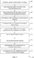
- FIG. 4 illustrates an exemplary method 500 for use in selectively positioning inspection sensor 102 relative to a target object, or structure 104, being inspected.
- control system 400 facilitates remotely positioning inspection sensor 102 to enable inspection and/or evaluation of structure 104. More specifically, the embodiments described herein enable a position of sensor 206, and as a result the position of the inspection sensor 102, to be accurately tracked using a three-dimensional CAD model of structure 104 in a three-dimensional coordinate system.
- articulated robotic system 200 is positioned 502 proximate and/or adjacent to a target object or structure 104.
- range meter 302 measures 504 a distance to an exterior position of structure 104, and measures 506 a distance to an exterior position of articulated robotic system 200.
- positional data is transmitted to control system 400 to enable control system 400 to accurately determine a position and/or an orientation of structure 104 and/or articulated robotic system 200 relative to local coordinate measurement system 300.
- triangulation techniques are used to determine the relative positions of structure 104 and articulated robotic system 200. Based at least on such positional data, in the exemplary embodiment, control system 400 determines 508 a first position of positioning sensor 206, which is coupled to articulated robotic system 200.
- At least one virtual representation of structure 104 is received 510 from memory device 402.
- a type of structure 104 may be identified and/or determined based on positional data of structure 104, and a virtual representation of structure 104 may be determined and/or selected based on the type of structure 104.
- a virtual representation of articulated robotic system 200 and/or positioning sensor 206 may be provided based on the first position of positioning sensor 206. The virtual representations of structure 104, robotic system 200 and/or positioning sensor 206 are then registered 512 on a three-dimensional coordinate system.
- articulated robotic system 200 actuates arm 204 to suitably position, orient, and/or move 514 inspection sensor 102 relative to structure 104 for inspection and/or evaluation of structure 104.
- user 412 may use graphical presentation interface 406 and/or input interface 408 to navigate arm 204 through an access port 112 and/or around other internal landmarks and/or obstructions 116.
- user 412 directs arm 204 past obstructions 116 inside structure 104 by watching a virtual display of structure 104, robotic arm 204, position sensor 206, and inspection sensor 102 on graphical presentation interface 406.
- Information from positioning sensor 206 is converted into the three-dimensional coordinate system in order to place the virtual objects in the proper positions and orientations on the graphical presentation interface 206.
- data provided by inspection sensor 102 and/or positioning sensor 206 may be used to enable partial and/or full automation of the navigation process to suitably position, orient, and/or move 514 inspection sensor 102 and/or positioning sensor 206.
- positional awareness data acquired and/or provided by positioning sensor 206 is continuously monitored and/or tracked 516 to provide real-time and post-processed position and/or orientation tracking as positioning sensor 206 is moved 514 from a first location to a second location relative to structure 104. More specifically, in the exemplary embodiment, movement of positioning sensor 206 is tracked 516 with respect to the position of structure 104, the first position of positioning sensor 206, and/or other data provided by positioning sensor 206 and/or inspection sensor 102. As such, in the exemplary embodiment, the second location of positioning sensor 206 may be determined 518 based at least on the first position of positioning sensor 206 and the movement tracked from the first position to the second position. In the exemplary embodiment, the position and/or orientation of positioning sensor 206 is continuously displayed on graphical presentation interface 406 in the three-dimensional coordinate system to virtually track movement of positioning sensor 206 through limited access areas of structure 104.
- data provided by inspection sensor 102 and/or positioning sensor 206 may be used to calibrate 520 the virtual representation of structure 104, articulated robotic system 200, and/or positioning sensor 206 on the three-dimensional coordinate system based at least on the position of structure 104 and/or the first and second positions of positioning sensor 206.
- local coordinate measurement system 300 facilitates calibrating structure 104 and/or articulated robot system 200 to the three-dimensional coordinate system. More specifically, in the exemplary embodiment, relative distances and/or angles between local coordinate measurement system 300, exterior feature 110, and exterior feature 210 are determined.
- any motion of arm 204 and positioning sensor 206 may then be converted into the three-dimensional coordinate system.
- obstructions 116 may be used to adjust and/or re-calibrate the positional data measured by positioning sensor 206. For example, if robot arm 204 is in contact with obstructions 116, which is at a known position, but the positioning sensor 206 is reporting a different position, the data from position sensor 206 may be adjusted to reference this known position of obstructions 116.
- an updated and/or recalibrated estimate position and/or orientation of inspection sensor 102 and/or positioning sensor 206 may be provided during operation.
- the virtual representation may be recalibrated, as necessary, when positional awareness data provided by inspection sensor 102 and/or positioning sensor 206 is not consistent with the virtual representation.
- the embodiments described herein provide for remotely placing and/or visualizing a sensor to inspect various components within limited access areas.
- the exemplary methods and systems facilitate reducing a time and/or cost associated with aircraft inspections.
- the exemplary systems and methods are not limited to the specific embodiments described herein, but rather, components of each system and/or steps of each method may be utilized independently and separately from other components and/or method steps described herein. Each component and each method step may also be used in combination with other components and/or method steps.
Landscapes
- Engineering & Computer Science (AREA)
- Robotics (AREA)
- Mechanical Engineering (AREA)
- Health & Medical Sciences (AREA)
- General Health & Medical Sciences (AREA)
- Orthopedic Medicine & Surgery (AREA)
- Length Measuring Devices With Unspecified Measuring Means (AREA)
- Manipulator (AREA)
Applications Claiming Priority (2)
| Application Number | Priority Date | Filing Date | Title |
|---|---|---|---|
| US12/787,885 US9149929B2 (en) | 2010-05-26 | 2010-05-26 | Methods and systems for inspection sensor placement |
| PCT/US2011/029717 WO2011149582A1 (en) | 2010-05-26 | 2011-03-24 | Methods and systems for inspection sensor placement |
Publications (2)
| Publication Number | Publication Date |
|---|---|
| EP2576156A1 EP2576156A1 (en) | 2013-04-10 |
| EP2576156B1 true EP2576156B1 (en) | 2019-05-29 |
Family
ID=44050149
Family Applications (1)
| Application Number | Title | Priority Date | Filing Date |
|---|---|---|---|
| EP11716337.8A Active EP2576156B1 (en) | 2010-05-26 | 2011-03-24 | Methods and systems for inspection sensor placement |
Country Status (6)
| Country | Link |
|---|---|
| US (1) | US9149929B2 (enExample) |
| EP (1) | EP2576156B1 (enExample) |
| JP (1) | JP5955316B2 (enExample) |
| CN (1) | CN102917844B (enExample) |
| AU (1) | AU2011258831B2 (enExample) |
| WO (1) | WO2011149582A1 (enExample) |
Families Citing this family (59)
| Publication number | Priority date | Publication date | Assignee | Title |
|---|---|---|---|---|
| US9082208B2 (en) * | 2011-07-12 | 2015-07-14 | Spirit Aerosystems, Inc. | System and method for locating and displaying aircraft information |
| US9310317B2 (en) | 2012-01-25 | 2016-04-12 | The Boeing Company | Automated system and method for tracking and detecting discrepancies on a target object |
| US9366579B2 (en) * | 2012-12-21 | 2016-06-14 | John Bean Technologies Corporation | Thermal process control |
| US9588515B2 (en) * | 2012-12-31 | 2017-03-07 | General Electric Company | Systems and methods for remote control of a non-destructive testing system |
| US9152304B2 (en) * | 2012-12-31 | 2015-10-06 | General Electric Company | Systems and methods for virtual control of a non-destructive testing system |
| US9581438B2 (en) * | 2012-12-31 | 2017-02-28 | General Electric Company | Systems and methods for control of a non-destructive testing system |
| US20140207406A1 (en) * | 2013-01-22 | 2014-07-24 | General Electric Company | Self-directed inspection plan |
| US9954908B2 (en) * | 2013-01-22 | 2018-04-24 | General Electric Company | Systems and methods for collaborating in a non-destructive testing system |
| US20140207403A1 (en) * | 2013-01-22 | 2014-07-24 | General Electric Company | Inspection instrument auto-configuration |
| US10725478B2 (en) * | 2013-07-02 | 2020-07-28 | The Boeing Company | Robotic-mounted monument system for metrology systems |
| US9395216B2 (en) * | 2013-10-22 | 2016-07-19 | The United States Of America, As Represented By The Secretary Of The Army | Disappearing controllable-arch sensor boom or crane |
| JP2015112708A (ja) * | 2013-12-16 | 2015-06-22 | 多摩川精機株式会社 | 締め装置及びその締め方法 |
| US9856037B2 (en) | 2014-06-18 | 2018-01-02 | The Boeing Company | Stabilization of an end of an extended-reach apparatus in a limited-access space |
| FR3028615B1 (fr) * | 2014-11-14 | 2017-01-13 | Aircelle Sa | Procede d’inspection d’un produit tel qu’un composant d’une nacelle de turboreacteur |
| US9911251B2 (en) * | 2014-12-15 | 2018-03-06 | Bosch Automotive Service Solutions Inc. | Vehicle diagnostic system and method |
| US9919421B2 (en) * | 2015-04-15 | 2018-03-20 | Abb Schweiz Ag | Method and apparatus for robot path teaching |
| CN106292655A (zh) * | 2015-06-25 | 2017-01-04 | 松下电器(美国)知识产权公司 | 远程作业装置和控制方法 |
| CN105092928B (zh) * | 2015-07-23 | 2018-04-20 | 深圳市华谊智测科技股份有限公司 | 数字钳型表及其自动测量方法 |
| US9841836B2 (en) * | 2015-07-28 | 2017-12-12 | General Electric Company | Control of non-destructive testing devices |
| US10196927B2 (en) * | 2015-12-09 | 2019-02-05 | General Electric Company | System and method for locating a probe within a gas turbine engine |
| GB2550395B (en) * | 2016-05-19 | 2020-08-12 | Hs Marston Aerospace Ltd | Method and system for thermographic analysis |
| EP3260250B1 (en) * | 2016-06-21 | 2019-10-02 | Ansaldo Energia IP UK Limited | Robotic system for confined space operations background |
| JP7061119B2 (ja) * | 2016-07-15 | 2022-04-27 | ファストブリック・アイピー・プロプライエタリー・リミテッド | 車両に組み込まれた煉瓦/ブロック敷設機 |
| FR3056134B1 (fr) * | 2016-09-20 | 2018-08-31 | Airbus Sas | Dispositif robotise pour l'inspection d'une structure d'aeronef |
| GB2557179B (en) * | 2016-11-29 | 2020-01-01 | Rolls Royce Plc | Methods, apparatus, computer programs and non-transitory computer readable storage mediums for controlling a hyper redundant manipulator |
| JP7019295B2 (ja) * | 2017-01-20 | 2022-02-15 | 東芝テック株式会社 | 情報収集装置および情報収集システム |
| US10814480B2 (en) | 2017-06-14 | 2020-10-27 | The Boeing Company | Stabilization of tool-carrying end of extended-reach arm of automated apparatus |
| US10625427B2 (en) | 2017-06-14 | 2020-04-21 | The Boeing Company | Method for controlling location of end effector of robot using location alignment feedback |
| US10543605B2 (en) * | 2017-08-15 | 2020-01-28 | Avigilon Corporation | Camera on movable arm |
| GB201713277D0 (en) * | 2017-08-18 | 2017-10-04 | Rolls Royce Plc | Hyper-redundant manipulators |
| TWI639988B (zh) * | 2017-10-05 | 2018-11-01 | 行政院原子能委員會核能研究所 | 移動機器人地圖創建系統和方法 |
| US10488349B2 (en) | 2017-11-14 | 2019-11-26 | General Electric Company | Automated borescope insertion system |
| US10489896B2 (en) | 2017-11-14 | 2019-11-26 | General Electric Company | High dynamic range video capture using variable lighting |
| DE102018103333B3 (de) | 2018-02-14 | 2019-05-09 | Gesellschaft zur Förderung angewandter Informatik eV | Verfahren und System zur dynamischen Strukturanalyse |
| US10775315B2 (en) | 2018-03-07 | 2020-09-15 | General Electric Company | Probe insertion system |
| FI128841B (en) * | 2018-03-22 | 2021-01-15 | Univ Helsinki | Sensor calibration |
| US11458641B2 (en) | 2018-05-23 | 2022-10-04 | General Electric Company | Robotic arm assembly construction |
| US11084169B2 (en) * | 2018-05-23 | 2021-08-10 | General Electric Company | System and method for controlling a robotic arm |
| US20190383158A1 (en) * | 2018-06-14 | 2019-12-19 | General Electric Company | Probe Motion Compensation |
| US11707819B2 (en) | 2018-10-15 | 2023-07-25 | General Electric Company | Selectively flexible extension tool |
| US12194620B2 (en) | 2018-10-15 | 2025-01-14 | Oliver Crisipin Robotics Limited | Selectively flexible extension tool |
| US11702955B2 (en) | 2019-01-14 | 2023-07-18 | General Electric Company | Component repair system and method |
| US11118948B2 (en) | 2019-08-23 | 2021-09-14 | Toyota Motor North America, Inc. | Systems and methods of calibrating vehicle sensors using augmented reality |
| US12405187B2 (en) | 2019-10-04 | 2025-09-02 | General Electric Company | Insertion apparatus for use with rotary machines |
| US10782267B1 (en) | 2019-11-04 | 2020-09-22 | Equate Petrochemical Company | Mobile non-destructive testing inspection system |
| US11752622B2 (en) | 2020-01-23 | 2023-09-12 | General Electric Company | Extension tool having a plurality of links |
| US11692650B2 (en) | 2020-01-23 | 2023-07-04 | General Electric Company | Selectively flexible extension tool |
| US11613003B2 (en) | 2020-01-24 | 2023-03-28 | General Electric Company | Line assembly for an extension tool having a plurality of links |
| US11371437B2 (en) | 2020-03-10 | 2022-06-28 | Oliver Crispin Robotics Limited | Insertion tool |
| US12091981B2 (en) | 2020-06-11 | 2024-09-17 | General Electric Company | Insertion tool and method |
| US12416800B2 (en) | 2021-01-08 | 2025-09-16 | General Electric Company | Insertion tool |
| US12504616B2 (en) | 2021-01-08 | 2025-12-23 | General Electric Company | Insertion tool |
| US11654547B2 (en) | 2021-03-31 | 2023-05-23 | General Electric Company | Extension tool |
| US11906506B1 (en) * | 2021-12-21 | 2024-02-20 | Omidreza Ghanadiof | System and method for inspecting and maintaining the exterior elevated elements of building structures |
| US12033314B2 (en) | 2021-12-21 | 2024-07-09 | Omidreza Ghanadiof | System and method for inspecting and maintaining the exterior elevated elements of building structures |
| US12318912B2 (en) | 2021-12-21 | 2025-06-03 | Omidreza Ghanadiof | System and method for inspecting and maintaining the exterior elevated elements of building structures |
| IT202200005888A1 (it) * | 2022-03-24 | 2023-09-24 | Bm Group Holding S P A | Apparecchiatura per effettuare misurazioni tra le gabbie in un processo di laminazione. |
| US20250076860A1 (en) * | 2023-08-31 | 2025-03-06 | Saudi Arabian Oil Company | Non-destructive testing inspection system |
| KR102875703B1 (ko) * | 2024-05-24 | 2025-10-22 | 한상민 | 지능형 픽 앤 플레이스 로봇 시스템의 로봇암 제어 장치 및 방법 |
Family Cites Families (44)
| Publication number | Priority date | Publication date | Assignee | Title |
|---|---|---|---|---|
| US4362977A (en) * | 1980-06-30 | 1982-12-07 | International Business Machines Corporation | Method and apparatus for calibrating a robot to compensate for inaccuracy of the robot |
| JPS6067093A (ja) * | 1983-09-22 | 1985-04-17 | 株式会社東芝 | 連続部材 |
| US5374830A (en) * | 1984-10-12 | 1994-12-20 | Sensor Adaptive Machines, Inc. | Target based determination of robot and sensor alignment |
| FR2625936A1 (fr) * | 1988-01-14 | 1989-07-21 | Hispano Suiza Sa | Procede de mise en place d'un robot porte-outils destine a des interventions en milieu humainement hostile |
| JPH0386484A (ja) * | 1989-08-25 | 1991-04-11 | Fujitsu Ltd | ロボットの遠隔操作装置 |
| US5525883A (en) * | 1994-07-08 | 1996-06-11 | Sara Avitzour | Mobile robot location determination employing error-correcting distributed landmarks |
| JPH08155863A (ja) * | 1994-12-02 | 1996-06-18 | Fujitsu Ltd | ロボット遠隔操作システム |
| JPH11104984A (ja) * | 1997-10-06 | 1999-04-20 | Fujitsu Ltd | 実環境情報表示装置及び実環境情報表示処理を実行するプログラムを記録したコンピュータ読み取り可能な記録媒体 |
| JP2000070269A (ja) | 1998-09-01 | 2000-03-07 | Honda Seiki Kk | 磁気センサー及び感圧センサーによりバーチャル・リアリティに誘導される能動内視鏡とその操作システム。 |
| US6379302B1 (en) * | 1999-10-28 | 2002-04-30 | Surgical Navigation Technologies Inc. | Navigation information overlay onto ultrasound imagery |
| GB0020461D0 (en) * | 2000-08-18 | 2000-10-11 | Oliver Crispin Consulting Ltd | Improvements in and relating to the robotic positioning of a work tool to a sensor |
| US6378387B1 (en) * | 2000-08-25 | 2002-04-30 | Aerobotics, Inc. | Non-destructive inspection, testing and evaluation system for intact aircraft and components and method therefore |
| FR2822573B1 (fr) * | 2001-03-21 | 2003-06-20 | France Telecom | Procede et systeme de reconstruction a distance d'une surface |
| JP2002292582A (ja) * | 2001-03-30 | 2002-10-08 | Hitachi Zosen Corp | 作業用ロボット装置 |
| US6907799B2 (en) * | 2001-11-13 | 2005-06-21 | Bae Systems Advanced Technologies, Inc. | Apparatus and method for non-destructive inspection of large structures |
| JP3945279B2 (ja) * | 2002-03-15 | 2007-07-18 | ソニー株式会社 | 障害物認識装置、障害物認識方法、及び障害物認識プログラム並びに移動型ロボット装置 |
| US7117067B2 (en) * | 2002-04-16 | 2006-10-03 | Irobot Corporation | System and methods for adaptive control of robotic devices |
| SE0203908D0 (sv) * | 2002-12-30 | 2002-12-30 | Abb Research Ltd | An augmented reality system and method |
| JP2004223128A (ja) * | 2003-01-27 | 2004-08-12 | Hitachi Ltd | 医療行為支援装置および方法 |
| US6822412B1 (en) * | 2003-06-11 | 2004-11-23 | Zhongxue Gan | Method for calibrating and programming of a robot application |
| US7044245B2 (en) * | 2003-06-17 | 2006-05-16 | Science Applications International Corporation | Toroidal propulsion and steering system |
| US7099745B2 (en) * | 2003-10-24 | 2006-08-29 | Sap Aktiengesellschaft | Robot system using virtual world |
| US8046049B2 (en) * | 2004-02-23 | 2011-10-25 | Biosense Webster, Inc. | Robotically guided catheter |
| JP4980899B2 (ja) * | 2004-06-25 | 2012-07-18 | カーネギー メロン ユニバーシティ | 操向可能なフォローザリーダー装置 |
| EP1701231A1 (en) * | 2005-03-08 | 2006-09-13 | Mydata Automation AB | Method of calibration |
| US7448271B2 (en) * | 2005-08-17 | 2008-11-11 | The Boeing Company | Inspection system and associated method |
| US7499772B2 (en) | 2005-08-31 | 2009-03-03 | Honeywell International Inc. | Method and system for navigating a nondestructive evaluation device |
| JP4734120B2 (ja) * | 2006-01-06 | 2011-07-27 | 株式会社東芝 | 航空機機体の検査方法および装置 |
| DE102006006246A1 (de) | 2006-02-10 | 2007-08-16 | Battenberg, Günther | Verfahren und Vorrichtung zur vollautomatischen Endkontrolle von Bauteilen und/oder deren Funktionseinheiten |
| US9186046B2 (en) * | 2007-08-14 | 2015-11-17 | Koninklijke Philips Electronics N.V. | Robotic instrument systems and methods utilizing optical fiber sensor |
| US20080004523A1 (en) * | 2006-06-29 | 2008-01-03 | General Electric Company | Surgical tool guide |
| KR20090057984A (ko) * | 2006-09-19 | 2009-06-08 | 더 트러스티이스 오브 콜롬비아 유니버시티 인 더 시티 오브 뉴욕 | 중공형 해부학적 부유 기관 상에서의 수술을 위한 시스템, 디바이스 및 방법 |
| US7892165B2 (en) * | 2006-10-23 | 2011-02-22 | Hoya Corporation | Camera calibration for endoscope navigation system |
| JP4298757B2 (ja) * | 2007-02-05 | 2009-07-22 | ファナック株式会社 | ロボット機構のキャリブレーション装置及び方法 |
| WO2008111692A1 (en) * | 2007-03-13 | 2008-09-18 | Research Institute Of Industrial Science & Technology | Landmark for position determination of mobile robot and apparatus and method using it |
| US8364312B2 (en) * | 2007-06-06 | 2013-01-29 | Cycogs, Llc | Modular rotary multi-sensor sensor ring |
| US8044991B2 (en) | 2007-09-28 | 2011-10-25 | The Boeing Company | Local positioning system and method |
| US7859655B2 (en) | 2007-09-28 | 2010-12-28 | The Boeing Company | Method involving a pointing instrument and a target object |
| US8138938B2 (en) | 2008-10-28 | 2012-03-20 | The Boeing Company | Hand-held positioning interface for spatial query |
| US8198617B2 (en) | 2008-12-15 | 2012-06-12 | The Boeing Company | Locating a component underneath a surface of a target object and locating an access panel for accessing the component |
| DE102009007932A1 (de) | 2009-02-06 | 2010-08-12 | Battenberg, Günther | Qualitätsgesteuertes Produktions- und Prüfverfahren |
| US7848894B2 (en) | 2009-03-09 | 2010-12-07 | The Boeing Company | Non-destructive inspection apparatus |
| US8812154B2 (en) * | 2009-03-16 | 2014-08-19 | The Boeing Company | Autonomous inspection and maintenance |
| WO2011138741A1 (en) * | 2010-05-04 | 2011-11-10 | Creaform Inc. | Object inspection with referenced volumetric analysis sensor |
-
2010
- 2010-05-26 US US12/787,885 patent/US9149929B2/en active Active
-
2011
- 2011-03-24 JP JP2013512617A patent/JP5955316B2/ja active Active
- 2011-03-24 AU AU2011258831A patent/AU2011258831B2/en active Active
- 2011-03-24 WO PCT/US2011/029717 patent/WO2011149582A1/en not_active Ceased
- 2011-03-24 CN CN201180025897.8A patent/CN102917844B/zh active Active
- 2011-03-24 EP EP11716337.8A patent/EP2576156B1/en active Active
Non-Patent Citations (1)
| Title |
|---|
| None * |
Also Published As
| Publication number | Publication date |
|---|---|
| CN102917844A (zh) | 2013-02-06 |
| AU2011258831A1 (en) | 2012-09-20 |
| US20110295427A1 (en) | 2011-12-01 |
| WO2011149582A1 (en) | 2011-12-01 |
| US9149929B2 (en) | 2015-10-06 |
| AU2011258831B2 (en) | 2016-02-25 |
| JP2013527040A (ja) | 2013-06-27 |
| CN102917844B (zh) | 2016-09-28 |
| EP2576156A1 (en) | 2013-04-10 |
| JP5955316B2 (ja) | 2016-07-20 |
Similar Documents
| Publication | Publication Date | Title |
|---|---|---|
| EP2576156B1 (en) | Methods and systems for inspection sensor placement | |
| JP5722224B2 (ja) | 空間照会のための手持ち型位置決めインタフェース | |
| EP2703776B1 (en) | Method and system for inspecting a workpiece | |
| US8305365B2 (en) | Mobile device and area-specific processing executing method | |
| US10286553B2 (en) | Methods and systems for automatically inspecting an object | |
| JP2022039903A (ja) | ラインレーザーセンサ用のキャリブレーションブロック及びハンドアイキャリブレーション方法 | |
| CN104251696A (zh) | 通过激光跟踪仪对维度数据的自动测量 | |
| WO2016049402A1 (en) | Augmented reality camera for use with 3d metrology equipment in forming 3d images from 2d camera images | |
| WO2008002918A2 (en) | Method and system for automatically performing a study of a multidimensional space | |
| JP7097251B2 (ja) | 施工管理システム | |
| CN208968469U (zh) | 工业机器人重复定位精度分析系统 | |
| CN101802738A (zh) | 用来检测环境的系统 | |
| CN115916480A (zh) | 机器人示教方法和机器人作业方法 | |
| CN113384347B (zh) | 一种机器人标定方法、装置、设备及存储介质 | |
| US12152879B1 (en) | Layout marking system for tracing reference regions in a construction layout and a method thereof | |
| CN112902965A (zh) | 机器人跨楼层轨迹的显示方法与系统 | |
| US20250129877A1 (en) | Systems and associated methods for multi-sensor robotic operation | |
| Al Rashed et al. | Inexpensive spatial position system for the automation of inspection with mobile robots |
Legal Events
| Date | Code | Title | Description |
|---|---|---|---|
| PUAI | Public reference made under article 153(3) epc to a published international application that has entered the european phase |
Free format text: ORIGINAL CODE: 0009012 |
|
| 17P | Request for examination filed |
Effective date: 20121205 |
|
| AK | Designated contracting states |
Kind code of ref document: A1 Designated state(s): AL AT BE BG CH CY CZ DE DK EE ES FI FR GB GR HR HU IE IS IT LI LT LU LV MC MK MT NL NO PL PT RO RS SE SI SK SM TR |
|
| DAX | Request for extension of the european patent (deleted) | ||
| STAA | Information on the status of an ep patent application or granted ep patent |
Free format text: STATUS: EXAMINATION IS IN PROGRESS |
|
| 17Q | First examination report despatched |
Effective date: 20161109 |
|
| GRAP | Despatch of communication of intention to grant a patent |
Free format text: ORIGINAL CODE: EPIDOSNIGR1 |
|
| STAA | Information on the status of an ep patent application or granted ep patent |
Free format text: STATUS: GRANT OF PATENT IS INTENDED |
|
| INTG | Intention to grant announced |
Effective date: 20181218 |
|
| GRAS | Grant fee paid |
Free format text: ORIGINAL CODE: EPIDOSNIGR3 |
|
| GRAA | (expected) grant |
Free format text: ORIGINAL CODE: 0009210 |
|
| STAA | Information on the status of an ep patent application or granted ep patent |
Free format text: STATUS: THE PATENT HAS BEEN GRANTED |
|
| AK | Designated contracting states |
Kind code of ref document: B1 Designated state(s): AL AT BE BG CH CY CZ DE DK EE ES FI FR GB GR HR HU IE IS IT LI LT LU LV MC MK MT NL NO PL PT RO RS SE SI SK SM TR |
|
| REG | Reference to a national code |
Ref country code: GB Ref legal event code: FG4D |
|
| REG | Reference to a national code |
Ref country code: CH Ref legal event code: EP |
|
| REG | Reference to a national code |
Ref country code: AT Ref legal event code: REF Ref document number: 1138003 Country of ref document: AT Kind code of ref document: T Effective date: 20190615 |
|
| REG | Reference to a national code |
Ref country code: DE Ref legal event code: R096 Ref document number: 602011059337 Country of ref document: DE |
|
| REG | Reference to a national code |
Ref country code: IE Ref legal event code: FG4D |
|
| REG | Reference to a national code |
Ref country code: NL Ref legal event code: MP Effective date: 20190529 |
|
| REG | Reference to a national code |
Ref country code: LT Ref legal event code: MG4D |
|
| PG25 | Lapsed in a contracting state [announced via postgrant information from national office to epo] |
Ref country code: AL Free format text: LAPSE BECAUSE OF FAILURE TO SUBMIT A TRANSLATION OF THE DESCRIPTION OR TO PAY THE FEE WITHIN THE PRESCRIBED TIME-LIMIT Effective date: 20190529 Ref country code: FI Free format text: LAPSE BECAUSE OF FAILURE TO SUBMIT A TRANSLATION OF THE DESCRIPTION OR TO PAY THE FEE WITHIN THE PRESCRIBED TIME-LIMIT Effective date: 20190529 Ref country code: LT Free format text: LAPSE BECAUSE OF FAILURE TO SUBMIT A TRANSLATION OF THE DESCRIPTION OR TO PAY THE FEE WITHIN THE PRESCRIBED TIME-LIMIT Effective date: 20190529 Ref country code: SE Free format text: LAPSE BECAUSE OF FAILURE TO SUBMIT A TRANSLATION OF THE DESCRIPTION OR TO PAY THE FEE WITHIN THE PRESCRIBED TIME-LIMIT Effective date: 20190529 Ref country code: ES Free format text: LAPSE BECAUSE OF FAILURE TO SUBMIT A TRANSLATION OF THE DESCRIPTION OR TO PAY THE FEE WITHIN THE PRESCRIBED TIME-LIMIT Effective date: 20190529 Ref country code: NO Free format text: LAPSE BECAUSE OF FAILURE TO SUBMIT A TRANSLATION OF THE DESCRIPTION OR TO PAY THE FEE WITHIN THE PRESCRIBED TIME-LIMIT Effective date: 20190829 Ref country code: PT Free format text: LAPSE BECAUSE OF FAILURE TO SUBMIT A TRANSLATION OF THE DESCRIPTION OR TO PAY THE FEE WITHIN THE PRESCRIBED TIME-LIMIT Effective date: 20190930 Ref country code: HR Free format text: LAPSE BECAUSE OF FAILURE TO SUBMIT A TRANSLATION OF THE DESCRIPTION OR TO PAY THE FEE WITHIN THE PRESCRIBED TIME-LIMIT Effective date: 20190529 |
|
| PG25 | Lapsed in a contracting state [announced via postgrant information from national office to epo] |
Ref country code: LV Free format text: LAPSE BECAUSE OF FAILURE TO SUBMIT A TRANSLATION OF THE DESCRIPTION OR TO PAY THE FEE WITHIN THE PRESCRIBED TIME-LIMIT Effective date: 20190529 Ref country code: GR Free format text: LAPSE BECAUSE OF FAILURE TO SUBMIT A TRANSLATION OF THE DESCRIPTION OR TO PAY THE FEE WITHIN THE PRESCRIBED TIME-LIMIT Effective date: 20190830 Ref country code: BG Free format text: LAPSE BECAUSE OF FAILURE TO SUBMIT A TRANSLATION OF THE DESCRIPTION OR TO PAY THE FEE WITHIN THE PRESCRIBED TIME-LIMIT Effective date: 20190829 Ref country code: RS Free format text: LAPSE BECAUSE OF FAILURE TO SUBMIT A TRANSLATION OF THE DESCRIPTION OR TO PAY THE FEE WITHIN THE PRESCRIBED TIME-LIMIT Effective date: 20190529 |
|
| REG | Reference to a national code |
Ref country code: AT Ref legal event code: MK05 Ref document number: 1138003 Country of ref document: AT Kind code of ref document: T Effective date: 20190529 |
|
| REG | Reference to a national code |
Ref country code: DE Ref legal event code: R082 Ref document number: 602011059337 Country of ref document: DE Representative=s name: MAIER, LL.M., MICHAEL C., DE Ref country code: DE Ref legal event code: R082 Ref document number: 602011059337 Country of ref document: DE Representative=s name: BOULT WADE TENNANT LLP, DE |
|
| PG25 | Lapsed in a contracting state [announced via postgrant information from national office to epo] |
Ref country code: RO Free format text: LAPSE BECAUSE OF FAILURE TO SUBMIT A TRANSLATION OF THE DESCRIPTION OR TO PAY THE FEE WITHIN THE PRESCRIBED TIME-LIMIT Effective date: 20190529 Ref country code: NL Free format text: LAPSE BECAUSE OF FAILURE TO SUBMIT A TRANSLATION OF THE DESCRIPTION OR TO PAY THE FEE WITHIN THE PRESCRIBED TIME-LIMIT Effective date: 20190529 Ref country code: AT Free format text: LAPSE BECAUSE OF FAILURE TO SUBMIT A TRANSLATION OF THE DESCRIPTION OR TO PAY THE FEE WITHIN THE PRESCRIBED TIME-LIMIT Effective date: 20190529 Ref country code: CZ Free format text: LAPSE BECAUSE OF FAILURE TO SUBMIT A TRANSLATION OF THE DESCRIPTION OR TO PAY THE FEE WITHIN THE PRESCRIBED TIME-LIMIT Effective date: 20190529 Ref country code: EE Free format text: LAPSE BECAUSE OF FAILURE TO SUBMIT A TRANSLATION OF THE DESCRIPTION OR TO PAY THE FEE WITHIN THE PRESCRIBED TIME-LIMIT Effective date: 20190529 Ref country code: DK Free format text: LAPSE BECAUSE OF FAILURE TO SUBMIT A TRANSLATION OF THE DESCRIPTION OR TO PAY THE FEE WITHIN THE PRESCRIBED TIME-LIMIT Effective date: 20190529 Ref country code: SK Free format text: LAPSE BECAUSE OF FAILURE TO SUBMIT A TRANSLATION OF THE DESCRIPTION OR TO PAY THE FEE WITHIN THE PRESCRIBED TIME-LIMIT Effective date: 20190529 |
|
| REG | Reference to a national code |
Ref country code: DE Ref legal event code: R082 Ref document number: 602011059337 Country of ref document: DE Representative=s name: BOULT WADE TENNANT LLP, DE |
|
| PG25 | Lapsed in a contracting state [announced via postgrant information from national office to epo] |
Ref country code: IT Free format text: LAPSE BECAUSE OF FAILURE TO SUBMIT A TRANSLATION OF THE DESCRIPTION OR TO PAY THE FEE WITHIN THE PRESCRIBED TIME-LIMIT Effective date: 20190529 Ref country code: SM Free format text: LAPSE BECAUSE OF FAILURE TO SUBMIT A TRANSLATION OF THE DESCRIPTION OR TO PAY THE FEE WITHIN THE PRESCRIBED TIME-LIMIT Effective date: 20190529 |
|
| REG | Reference to a national code |
Ref country code: DE Ref legal event code: R097 Ref document number: 602011059337 Country of ref document: DE |
|
| PG25 | Lapsed in a contracting state [announced via postgrant information from national office to epo] |
Ref country code: TR Free format text: LAPSE BECAUSE OF FAILURE TO SUBMIT A TRANSLATION OF THE DESCRIPTION OR TO PAY THE FEE WITHIN THE PRESCRIBED TIME-LIMIT Effective date: 20190529 |
|
| PLBE | No opposition filed within time limit |
Free format text: ORIGINAL CODE: 0009261 |
|
| STAA | Information on the status of an ep patent application or granted ep patent |
Free format text: STATUS: NO OPPOSITION FILED WITHIN TIME LIMIT |
|
| PG25 | Lapsed in a contracting state [announced via postgrant information from national office to epo] |
Ref country code: PL Free format text: LAPSE BECAUSE OF FAILURE TO SUBMIT A TRANSLATION OF THE DESCRIPTION OR TO PAY THE FEE WITHIN THE PRESCRIBED TIME-LIMIT Effective date: 20190529 |
|
| 26N | No opposition filed |
Effective date: 20200303 |
|
| PG25 | Lapsed in a contracting state [announced via postgrant information from national office to epo] |
Ref country code: SI Free format text: LAPSE BECAUSE OF FAILURE TO SUBMIT A TRANSLATION OF THE DESCRIPTION OR TO PAY THE FEE WITHIN THE PRESCRIBED TIME-LIMIT Effective date: 20190529 |
|
| PG25 | Lapsed in a contracting state [announced via postgrant information from national office to epo] |
Ref country code: MC Free format text: LAPSE BECAUSE OF FAILURE TO SUBMIT A TRANSLATION OF THE DESCRIPTION OR TO PAY THE FEE WITHIN THE PRESCRIBED TIME-LIMIT Effective date: 20190529 |
|
| REG | Reference to a national code |
Ref country code: CH Ref legal event code: PL |
|
| REG | Reference to a national code |
Ref country code: BE Ref legal event code: MM Effective date: 20200331 |
|
| PG25 | Lapsed in a contracting state [announced via postgrant information from national office to epo] |
Ref country code: LU Free format text: LAPSE BECAUSE OF NON-PAYMENT OF DUE FEES Effective date: 20200324 |
|
| PG25 | Lapsed in a contracting state [announced via postgrant information from national office to epo] |
Ref country code: CH Free format text: LAPSE BECAUSE OF NON-PAYMENT OF DUE FEES Effective date: 20200331 Ref country code: IE Free format text: LAPSE BECAUSE OF NON-PAYMENT OF DUE FEES Effective date: 20200324 Ref country code: LI Free format text: LAPSE BECAUSE OF NON-PAYMENT OF DUE FEES Effective date: 20200331 |
|
| PG25 | Lapsed in a contracting state [announced via postgrant information from national office to epo] |
Ref country code: BE Free format text: LAPSE BECAUSE OF NON-PAYMENT OF DUE FEES Effective date: 20200331 |
|
| PG25 | Lapsed in a contracting state [announced via postgrant information from national office to epo] |
Ref country code: MT Free format text: LAPSE BECAUSE OF FAILURE TO SUBMIT A TRANSLATION OF THE DESCRIPTION OR TO PAY THE FEE WITHIN THE PRESCRIBED TIME-LIMIT Effective date: 20190529 Ref country code: CY Free format text: LAPSE BECAUSE OF FAILURE TO SUBMIT A TRANSLATION OF THE DESCRIPTION OR TO PAY THE FEE WITHIN THE PRESCRIBED TIME-LIMIT Effective date: 20190529 |
|
| PG25 | Lapsed in a contracting state [announced via postgrant information from national office to epo] |
Ref country code: MK Free format text: LAPSE BECAUSE OF FAILURE TO SUBMIT A TRANSLATION OF THE DESCRIPTION OR TO PAY THE FEE WITHIN THE PRESCRIBED TIME-LIMIT Effective date: 20190529 Ref country code: IS Free format text: LAPSE BECAUSE OF FAILURE TO SUBMIT A TRANSLATION OF THE DESCRIPTION OR TO PAY THE FEE WITHIN THE PRESCRIBED TIME-LIMIT Effective date: 20190929 |
|
| P01 | Opt-out of the competence of the unified patent court (upc) registered |
Effective date: 20230516 |
|
| PGFP | Annual fee paid to national office [announced via postgrant information from national office to epo] |
Ref country code: GB Payment date: 20260327 Year of fee payment: 16 |
|
| PGFP | Annual fee paid to national office [announced via postgrant information from national office to epo] |
Ref country code: DE Payment date: 20260327 Year of fee payment: 16 |
|
| PGFP | Annual fee paid to national office [announced via postgrant information from national office to epo] |
Ref country code: FR Payment date: 20260325 Year of fee payment: 16 |