EP2574819A1 - Amortisseur d'oscillations actif à vitesse proportionnelle - Google Patents
Amortisseur d'oscillations actif à vitesse proportionnelle Download PDFInfo
- Publication number
- EP2574819A1 EP2574819A1 EP11183451A EP11183451A EP2574819A1 EP 2574819 A1 EP2574819 A1 EP 2574819A1 EP 11183451 A EP11183451 A EP 11183451A EP 11183451 A EP11183451 A EP 11183451A EP 2574819 A1 EP2574819 A1 EP 2574819A1
- Authority
- EP
- European Patent Office
- Prior art keywords
- mechanical structure
- damping
- control device
- operating method
- vibration damper
- Prior art date
- Legal status (The legal status is an assumption and is not a legal conclusion. Google has not performed a legal analysis and makes no representation as to the accuracy of the status listed.)
- Granted
Links
- 230000010355 oscillation Effects 0.000 title claims description 8
- 238000013016 damping Methods 0.000 claims abstract description 125
- 238000011017 operating method Methods 0.000 claims description 29
- 230000003534 oscillatory effect Effects 0.000 claims description 14
- 238000000034 method Methods 0.000 claims description 13
- 238000005516 engineering process Methods 0.000 claims description 5
- 230000001133 acceleration Effects 0.000 description 6
- 238000013459 approach Methods 0.000 description 4
- 238000013461 design Methods 0.000 description 3
- 230000005284 excitation Effects 0.000 description 3
- 238000001914 filtration Methods 0.000 description 3
- 238000012545 processing Methods 0.000 description 3
- 230000010354 integration Effects 0.000 description 2
- 239000002655 kraft paper Substances 0.000 description 2
- 230000010363 phase shift Effects 0.000 description 2
- 230000036962 time dependent Effects 0.000 description 2
- 230000009471 action Effects 0.000 description 1
- 230000004913 activation Effects 0.000 description 1
- 230000002238 attenuated effect Effects 0.000 description 1
- 238000005311 autocorrelation function Methods 0.000 description 1
- 230000015572 biosynthetic process Effects 0.000 description 1
- 230000001276 controlling effect Effects 0.000 description 1
- 230000001419 dependent effect Effects 0.000 description 1
- 238000001514 detection method Methods 0.000 description 1
- 238000006073 displacement reaction Methods 0.000 description 1
- 230000000694 effects Effects 0.000 description 1
- 230000005484 gravity Effects 0.000 description 1
- 230000008569 process Effects 0.000 description 1
- 230000001105 regulatory effect Effects 0.000 description 1
- 230000003068 static effect Effects 0.000 description 1
Images
Classifications
-
- F—MECHANICAL ENGINEERING; LIGHTING; HEATING; WEAPONS; BLASTING
- F16—ENGINEERING ELEMENTS AND UNITS; GENERAL MEASURES FOR PRODUCING AND MAINTAINING EFFECTIVE FUNCTIONING OF MACHINES OR INSTALLATIONS; THERMAL INSULATION IN GENERAL
- F16F—SPRINGS; SHOCK-ABSORBERS; MEANS FOR DAMPING VIBRATION
- F16F15/00—Suppression of vibrations in systems; Means or arrangements for avoiding or reducing out-of-balance forces, e.g. due to motion
- F16F15/002—Suppression of vibrations in systems; Means or arrangements for avoiding or reducing out-of-balance forces, e.g. due to motion characterised by the control method or circuitry
-
- B—PERFORMING OPERATIONS; TRANSPORTING
- B66—HOISTING; LIFTING; HAULING
- B66C—CRANES; LOAD-ENGAGING ELEMENTS OR DEVICES FOR CRANES, CAPSTANS, WINCHES, OR TACKLES
- B66C13/00—Other constructional features or details
- B66C13/04—Auxiliary devices for controlling movements of suspended loads, or preventing cable slack
- B66C13/06—Auxiliary devices for controlling movements of suspended loads, or preventing cable slack for minimising or preventing longitudinal or transverse swinging of loads
- B66C13/066—Auxiliary devices for controlling movements of suspended loads, or preventing cable slack for minimising or preventing longitudinal or transverse swinging of loads for minimising vibration of a boom
-
- F—MECHANICAL ENGINEERING; LIGHTING; HEATING; WEAPONS; BLASTING
- F16—ENGINEERING ELEMENTS AND UNITS; GENERAL MEASURES FOR PRODUCING AND MAINTAINING EFFECTIVE FUNCTIONING OF MACHINES OR INSTALLATIONS; THERMAL INSULATION IN GENERAL
- F16F—SPRINGS; SHOCK-ABSORBERS; MEANS FOR DAMPING VIBRATION
- F16F7/00—Vibration-dampers; Shock-absorbers
- F16F7/10—Vibration-dampers; Shock-absorbers using inertia effect
- F16F7/1005—Vibration-dampers; Shock-absorbers using inertia effect characterised by active control of the mass
- F16F7/1011—Vibration-dampers; Shock-absorbers using inertia effect characterised by active control of the mass by electromagnetic means
Definitions
- the present invention further relates to a control program comprising machine code directly executable by a control device for an active vibration damper, wherein the execution of the machine code by the control device causes the control device to operate the active vibration damper according to such an operation method.
- the present invention further relates to a control device for an active vibration damper, wherein the control device is designed or programmed such that it operates the active vibration damper according to such an operating method.
- An active vibration damper in which a movable mass is connected via leaf springs to the oscillatory mechanical structure.
- the movable mass is controlled by an electric linear drive.
- An active vibration damper in which a movable mass acts on the oscillatory mechanical structure via a spring.
- the mobile one Mass is applied on its side facing away from the mechanical structure with a signal, so that the speed of the movable mass is proportional to the deflection of the mechanical structure.
- a vibration damper is known, which is alternatively operable as an active or passive vibration damper.
- passive operation a movable mass is coupled via a spring to the oscillatory mechanical structure to resonate with the mechanical structure.
- a spring is coupled via a spring to the oscillatory mechanical structure to resonate with the mechanical structure.
- an active vibration damper in which a pendulum mass is deflected on a circular curved path, so that - as in the pendulum of a clock - gravity acts as a restoring force.
- the position and speed of the mechanical structure are compared with the position and speed of the pendulum mass.
- the pendulum mass is controlled such that the pendulum mass oscillates with a phase shift of 90 ° to the mechanical structure.
- the object of the present invention is to provide opportunities by means of which occurring vibrations can be damped in an efficient manner and suppressed as equal as possible in the approach.
- a proportionality factor between the instantaneous velocity of the mechanical structure and the damping force exerted on the mechanical structure of the control device can be specified from the outside.
- the damping of the vibration is adjustable as needed.
- the control device it is possible, for example, for the control device to execute a control program for executing the operating method, and for the control device to accept the proportionality factor as parameter during the execution of the control program.
- the control device can automatically adjust a proportionality factor between the instantaneous velocity of the mechanical structure and the damping force exerted on the mechanical structure in such a way that natural oscillation of the mechanical structure is damped in a predetermined manner. By doing this a self-adapting operation of the active vibration damper.
- the extent to which a resulting vibration is damped may be determined as needed.
- a resulting damping of a vibration of the mechanical structure may be at most as great as the limit damping required for achieving the aperiodic limit case of a natural vibration of the mechanical structure.
- the damping drive is designed as an electric direct linear drive, which has a stator, wherein the stator is fixedly connected to the mechanical structure and on the one hand acts on the mechanical structure and on the other hand on a relative to the mechanical structure movable rotor.
- Equation 2 vD * is the desired velocity of the rotor relative to the vibratory mechanical structure.
- x is the deflection of the mechanical structure from a reference position.
- m and d have the same meaning as in equation 1.
- the control device can thus determine a deflection of the mechanical structure from a reference position and determine the instantaneous speed of the mechanical structure at any time proportional damping force indirectly by determining a target speed of the rotor relative to the mechanical structure such that the desired speed at any time proportional to the instantaneous deflection of mechanical structure is out of the reference position.
- the control of the damping drive is embedded in a superimposed position control according to the determined damping force, due to which a deflection of the rotor caused by the control of the damping drive in accordance with the determined damping force is superimposed on a return movement from a rest position related to the mechanical structure, by means of which the rotor will move to the rest position or to a rest area containing the rest position and / or that the method of the rotor is limited by the control device to a permissible travel range containing the rest position. This ensures that the rotor is moved only within its permissible travel range.
- an additional mass can be arranged on the rotor of the electric direct linear drive.
- control program according to claim 10.
- the execution of the machine code by the control device causes the control device to operate the active vibration damper according to an operating method according to the invention.
- control device having the features of claim 11.
- the control device is designed or programmed in such a way that that it operates the active vibration damper according to an operating method according to the invention.
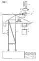
- FIG. 1 schematically shows a container crane 1.
- the container crane 1 has a crane frame 2, which in turn includes a boom 3 among other things.
- a trolley 4 On the boom 3, a trolley 4 is movable.
- a so-called spreader 5 On the trolley 4, a so-called spreader 5 is lowered and arranged liftable. By means of the spreader 5 container 6 can be taken and implemented.
- Container cranes 1 like the one in FIG. 1 shown container crane 1 are often used in port facilities for container handling from country to ship and vice versa.
- the vibration is relatively low frequency, typically below one hertz. It can be relatively long-stroke, for example, up to one meter.
- the crane frame 2 is therefore a vibratory mechanical structure 2 in the sense of the present invention.
- Vibrations of the oscillatory mechanical structure 2 are to be damped.
- An active vibration damper is available for this purpose.
- the active vibration damper has a damping device, by means of which a force FD * - hereinafter called damping force FD * - can be imprinted directly into the oscillatory structure 2.
- the damping device is arranged on the oscillatory structure 2. It comprises a damping drive 8.
- the active vibration damper furthermore has a control device 9 and sensors 10.
- the damping drive 8 is preferably designed as an electrical direct linear drive.
- the stator of the damping drive 8 is fixedly connected to the mechanical structure 2.
- the stator acts on the one hand on the mechanical structure 2 and on the other hand on a relative to the stator and thus also relative to the mechanical structure 2 movable rotor of the damping drive 8.
- an additional mass 7 may be arranged on the rotor.
- the movable mass - ie the mass of the rotor plus the mass of the additional mass 7 - is movable relative to the oscillatory mechanical structure 2.
- the damping drive 8 is arranged on the oscillatory mechanical structure 2 and firmly connected to it. He acts on the moving mass.
- the damping drive 8 By means of the damping drive 8, the movable mass is movable relative to the oscillatory mechanical structure 2.
- the movable mass in turn acts only on the damping drive 8 on the mechanical structure. 2
- an absolute movement of the oscillatory mechanical structure 2 in space can be detected.
- the control device 9 is connected to the sensors 10 for receiving the variables a detected by the sensors 6 in terms of data technology. It is designed such that it operates the active vibration damper according to an operating method, which will be explained in more detail below.
- the control device 9 is generally designed as a software programmable control device 9. The operation of the control device 9 is therefore determined by a control program 11, with which the control device 9 is programmed, which thus causes the corresponding formation of the control device 9.
- control device 9 generally has a microprocessor 12 internally.
- the control program 11 comprises machine code 13 which can be processed directly by the control device 9 (more precisely: the microprocessor 12 of the control device 9).
- the processing of the machine code 13 causes the control device 9 operates the active vibration damper according to the operating method according to the invention.
- the control program 11 can be supplied to the control device 9 in any desired manner.
- the control program 11 may be stored in a machine-readable form-in particular in electronic form-on a data carrier 14, and supplied to the control device 9 via the data carrier 14.
- the data carrier 14 is according to FIG FIG. 1 designed as a USB memory stick. However, this configuration can be readily varied.
- x is the deflection of the mechanical structure 2 from a - in principle freely selectable - reference position x0.
- v is the first time derivative of the deflection x, ie the velocity of the mechanical structure 2.
- a is the second time derivative of the deflection x, ie the acceleration of the mechanical structure 2.
- ⁇ 0 is a circular natural frequency, ie the natural frequency multiplied by 2 ⁇ a natural vibration of the mechanical structure 2.
- d is a damping factor.
- F is an external stimulus.
- the quantities x, v and a are time-dependent.
- the quantities ⁇ 0 and d are constant over time.
- the external force F can be time-dependent (forced oscillation) or constant, in particular having the value 0 (free oscillation).
- the mechanical structure 2 itself - ie without taking into account the active vibration damper - often has only a very small damping factor d (d / ⁇ 0 ⁇ 1). In most cases, the quotient of the damping factor d to the natural angular frequency ⁇ 0 is less than 0.1, often even less than 0.01. However, by means of the drive mode of the active vibration damper according to the invention, which is explained below, the effective damping factor d can be significantly increased. It may even be raised to such an extent that the resulting damping of the vibration of the mechanical structure 2 is at least as great as the limit damping required to achieve the aperiodic limit of the natural vibration of the mechanical structure 2. It is thus possible to determine the damping factor d in such a way that it holds d ⁇ ⁇ 0
- the damping factor d can be fixed. Preferably, however, it is adjustable.
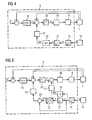
- the output signal of the multiplier 16 is - optionally after filtering in a filter 17 - supplied as desired damping force FD * a force regulator 18, which in turn acts on the damping drive 8.
- the control device 9 is connected to the damping drive 8 in terms of control engineering.
- the damping drive 8 is thus controlled by the control device 9 in accordance with the determined damping force FD *.
- the damping drive 8 is supported on the mechanical structure 2 and acts on the movable mass, the damping force FD * is thus impressed directly on the mechanical structure 2. Since the damping force FD * due to the above in connection with FIG. 2 has been determined by the control device 9, the force exerted by the movable mass on the damping drive 8 on the mechanical structure 2 damping force FD * at any time proportional to the instantaneous speed v of the mechanical structure 2. The vibration of the mechanical structure 2 is thus attenuated accordingly.
- the previously described structure of FIG. 2 according to FIG. 2 be extended by a position controller 19 and a subordinate speed controller 20.
- the speed controller 20 may be formed for example as a P-controller or as a PI controller.
- the position controller 19 is preset as a setpoint to the mechanical structure 2 fixed fixed position setpoint x '*, which should be approximately in the middle of the permissible travel range of the rotor.
- the actual position x 'of the rotor relative to the mechanical structure 2 is fed to the position controller 19 as an actual value.
- the position controller 19 determines on the basis of the position setpoint x '* and the actual position x' an additional setpoint speed v '*, which is supplied to the speed controller 20 as its setpoint. As an actual value, the speed controller 20 is supplied with the actual speed v 'of the rotor relative to the mechanical structure 2. The speed controller 20 determines based on the target-actual comparison, an additional force target value F '*, which is added to the damping force FD * of the multiplier 16 additively.
- the control of the damping drive 8 is thus superimposed on the position control in accordance with the damping force FD *. Due to the design of the position controller 19 as a PI controller in conjunction with the specification of the fixed position setpoint x '* the deflection of the rotor caused by the damping force FD * is thus superimposed on a return movement, by means of which the rotor will move to a rest position.
- the desired position value x '* could also be varied, for example, within a rest region containing the rest position, in common mode or in push-pull to the actual movement of the rotor relative to the mechanical structure 2.
- the rest area is in this case a (usually relatively small ) Subarea of the permissible travel range.
- control device 9 could, for example, detect the actual travel path of the rotor and modify the activation of the damping drive 8 in such a way that the process of the rotor is limited to the permissible travel range.
- Damping factor d corresponds to a proportionality factor between the instantaneous velocity v of the mechanical structure 2 and the damping force FD * exerted on the mechanical structure 2.
- the damping factor d of the control device 9 is fixed, for example, determined by the control program 11 as such.
- the control device 9 executes the control program 11 for executing the operating method, there may thus be the possibility that the control device 9 accepts the damping factor d as a parameter during the execution of the control program 11.
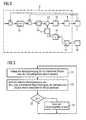
- control device 9 it is possible for the control device 9 to automatically adjust the damping factor d in such a way that a natural vibration of the mechanical structure is damped in a predetermined manner. This will be described below in connection with FIG. 3 explained in more detail.
- the control device 9 detects the absolute movement of the mechanical structure 2 in a step S1.
- the damping factor d is kept constant during this period.
- step S2 the control device 9 evaluates the detected absolute movement (more precisely, its time profile).
- the controller 9 may be a Fourier analysis or determine an autocorrelation function.
- the result of step S2 is the value of a logical variable OK.
- the logical variable OK assumes the value TRUE if and only if a predetermined natural vibration of the mechanical structure 2 - for example its fundamental vibration - is damped in a predetermined manner. For example, it may be determined that attenuation of at least 50% (or 70% or other suitable value) occurs per period of the corresponding natural vibration.
- step S3 the controller 9 checks the value of the logical variable OK. If the logical variable OK is TRUE, no further action is taken. Otherwise, the control device 9 in a step S4, the damping factor d according to such that the corresponding natural vibration is damped in the desired manner.
- the velocity v of the mechanical structure 2 is integrated in a further integrator 21 and thus determines the deflection x of the mechanical structure 2 from the reference position x0.
- the displacement x is multiplied in a multiplier 22 by the factor d / m, where d is the desired damping factor and m is the mass of the movable Are mass.
- filtering takes place in a filter 23.
- the value thus determined corresponds to a desired speed vD * of the rotor relative to the mechanical structure 2. It is supplied to the speed controller 20 as a compensation setpoint.
- the damping force FD * is thus indirectly determined by the control device 9 determining the desired speed vD * of the movable mass relative to the mechanical structure 2, wherein the desired speed vD * is always proportional to the instantaneous deflection x of the mechanical structure 2 from the reference position x0.
- the vibration to be damped can according to the example of FIG. 1 to be a translational vibration.
- a torsional vibration or a torsional vibration come into question.
- the damping drive 8 may be formed in such cases as a rotary drive.
- the damping drive 8, as already mentioned, corresponding to the name "LIN" in FIG. 1 is designed as an electrical direct linear drive.
- the present invention has many advantages. In particular, a highly efficient damping of almost any vibration is possible in a simple manner.
Landscapes
- Engineering & Computer Science (AREA)
- General Engineering & Computer Science (AREA)
- Mechanical Engineering (AREA)
- Physics & Mathematics (AREA)
- Acoustics & Sound (AREA)
- Aviation & Aerospace Engineering (AREA)
- Electromagnetism (AREA)
- Vibration Prevention Devices (AREA)
Priority Applications (3)
| Application Number | Priority Date | Filing Date | Title |
|---|---|---|---|
| EP11183451.1A EP2574819B1 (fr) | 2011-09-30 | 2011-09-30 | Amortisseur d'oscillations actif à vitesse proportionnelle |
| US13/630,812 US9316283B2 (en) | 2011-09-30 | 2012-09-28 | Velocity-proportional active vibration damping |
| CN201210372252.8A CN103032513B (zh) | 2011-09-30 | 2012-09-28 | 速度成比例的主动减振系统 |
Applications Claiming Priority (1)
| Application Number | Priority Date | Filing Date | Title |
|---|---|---|---|
| EP11183451.1A EP2574819B1 (fr) | 2011-09-30 | 2011-09-30 | Amortisseur d'oscillations actif à vitesse proportionnelle |
Publications (2)
| Publication Number | Publication Date |
|---|---|
| EP2574819A1 true EP2574819A1 (fr) | 2013-04-03 |
| EP2574819B1 EP2574819B1 (fr) | 2014-04-23 |
Family
ID=44719616
Family Applications (1)
| Application Number | Title | Priority Date | Filing Date |
|---|---|---|---|
| EP11183451.1A Active EP2574819B1 (fr) | 2011-09-30 | 2011-09-30 | Amortisseur d'oscillations actif à vitesse proportionnelle |
Country Status (3)
| Country | Link |
|---|---|
| US (1) | US9316283B2 (fr) |
| EP (1) | EP2574819B1 (fr) |
| CN (1) | CN103032513B (fr) |
Cited By (1)
| Publication number | Priority date | Publication date | Assignee | Title |
|---|---|---|---|---|
| WO2019007541A1 (fr) * | 2017-07-03 | 2019-01-10 | Liebherr-Components Biberach Gmbh | Grue et procédé pour commander ladite grue |
Families Citing this family (8)
| Publication number | Priority date | Publication date | Assignee | Title |
|---|---|---|---|---|
| KR101525741B1 (ko) * | 2014-07-29 | 2015-06-04 | 단국대학교 산학협력단 | 능동질량감쇠장치의 최적제어력 산정 및 제어방법 |
| EP2988181B1 (fr) | 2014-08-19 | 2019-07-03 | Siemens Aktiengesellschaft | Dispositif de réglage à compensation d'erreur adaptative |
| EP3056464A1 (fr) | 2015-02-11 | 2016-08-17 | Siemens Aktiengesellschaft | Commande de grue automatisée tenant compte des erreurs de mesure de charge et de poids |
| EP3115857A1 (fr) | 2015-07-09 | 2017-01-11 | Siemens Aktiengesellschaft | Procédé de détermination de trajectoire pour mouvements de temps mort |
| JP2017072219A (ja) | 2015-10-08 | 2017-04-13 | キヤノン株式会社 | 振動制御装置、リソグラフィ装置、および物品の製造方法 |
| EP3176657A1 (fr) | 2015-12-02 | 2017-06-07 | Siemens Aktiengesellschaft | Determination de la rigidite d'une chaine cinematique d'une machine, en particulier d'une machine de production ou d'une machine-outil |
| JP6446020B2 (ja) * | 2016-11-29 | 2018-12-26 | 本田技研工業株式会社 | 能動型防振装置及び能動型防振方法 |
| JP7445616B2 (ja) | 2021-03-19 | 2024-03-07 | 株式会社三井E&S | 岸壁クレーンおよびその制御方法 |
Citations (10)
| Publication number | Priority date | Publication date | Assignee | Title |
|---|---|---|---|---|
| US4083433A (en) * | 1976-11-16 | 1978-04-11 | Westinghouse Electric Corporation | Active vibration damper with electrodynamic sensor and drive units |
| US4635892A (en) | 1985-08-19 | 1987-01-13 | Vibrastop, Inc. | Active vibration suppressor |
| JPH03200694A (ja) | 1989-12-28 | 1991-09-02 | Ishikawajima Yusoki Kk | クレーン |
| US5255764A (en) | 1989-06-06 | 1993-10-26 | Takafumi Fujita | Active/passive damping apparatus |
| EP0841296A1 (fr) | 1996-11-07 | 1998-05-13 | Ishikawajima-Harima Jukogyo Kabushiki Kaisha | Grue de container |
| WO2003000004A2 (fr) | 2001-06-22 | 2003-01-03 | True Gravity Enterprises, Inc. | Systeme autonome de commande de mouvement par trains d'impulsions intermittents |
| US20050082994A1 (en) | 2001-12-14 | 2005-04-21 | Songgang Qiu | Active balance system and vibration balanced machine |
| GB2447231A (en) | 2007-03-05 | 2008-09-10 | Ian Mcgregor Stothers | An active tuned vibration absorber and a system for controlling such an absorber |
| EP2023007A1 (fr) * | 2006-05-08 | 2009-02-11 | Shinko Electric Co., Ltd | Amortisseur pour automobiles pour réduire les vibrations d'une carrosserie automobile |
| EP2327651A1 (fr) * | 2009-11-30 | 2011-06-01 | Siemens Aktiengesellschaft | Système d'amortissement d'une oscillation sur une grue de conteneur |
Family Cites Families (10)
| Publication number | Priority date | Publication date | Assignee | Title |
|---|---|---|---|---|
| IT1163942B (it) * | 1983-09-27 | 1987-04-08 | Honeywell Inf Systems | Gruppo elettromagnetico di stampa per stampante a mosaico |
| US4887699A (en) * | 1989-02-10 | 1989-12-19 | Lord Corporation | Vibration attenuating method utilizing continuously variable semiactive damper |
| US5393735A (en) * | 1990-08-09 | 1995-02-28 | Rohm And Haas Company | Herbicidal glutarimides |
| US5062657A (en) * | 1989-11-02 | 1991-11-05 | General Motors Corporation | On/off semi-active suspension control |
| US5033028A (en) * | 1989-12-27 | 1991-07-16 | At&T Bell Laboratories | Reaction mass actuator |
| JP4056384B2 (ja) | 2002-12-27 | 2008-03-05 | 三菱重工業株式会社 | アクティブダンパー制御装置、制振装置及びアクティブダンパー制御方法 |
| JP2009137545A (ja) * | 2007-12-10 | 2009-06-25 | Toyota Motor Corp | 減衰力制御装置 |
| CN101220845B (zh) | 2008-01-23 | 2010-11-24 | 重庆大学 | 一种基于组合悬置的发动机隔振系统及控制方法 |
| JP5278202B2 (ja) | 2009-07-02 | 2013-09-04 | 日産自動車株式会社 | 振動低減装置 |
| CN102232027B (zh) | 2010-02-17 | 2013-11-06 | 丰田自动车株式会社 | 车辆用减振力控制方法 |
-
2011
- 2011-09-30 EP EP11183451.1A patent/EP2574819B1/fr active Active
-
2012
- 2012-09-28 US US13/630,812 patent/US9316283B2/en active Active
- 2012-09-28 CN CN201210372252.8A patent/CN103032513B/zh active Active
Patent Citations (10)
| Publication number | Priority date | Publication date | Assignee | Title |
|---|---|---|---|---|
| US4083433A (en) * | 1976-11-16 | 1978-04-11 | Westinghouse Electric Corporation | Active vibration damper with electrodynamic sensor and drive units |
| US4635892A (en) | 1985-08-19 | 1987-01-13 | Vibrastop, Inc. | Active vibration suppressor |
| US5255764A (en) | 1989-06-06 | 1993-10-26 | Takafumi Fujita | Active/passive damping apparatus |
| JPH03200694A (ja) | 1989-12-28 | 1991-09-02 | Ishikawajima Yusoki Kk | クレーン |
| EP0841296A1 (fr) | 1996-11-07 | 1998-05-13 | Ishikawajima-Harima Jukogyo Kabushiki Kaisha | Grue de container |
| WO2003000004A2 (fr) | 2001-06-22 | 2003-01-03 | True Gravity Enterprises, Inc. | Systeme autonome de commande de mouvement par trains d'impulsions intermittents |
| US20050082994A1 (en) | 2001-12-14 | 2005-04-21 | Songgang Qiu | Active balance system and vibration balanced machine |
| EP2023007A1 (fr) * | 2006-05-08 | 2009-02-11 | Shinko Electric Co., Ltd | Amortisseur pour automobiles pour réduire les vibrations d'une carrosserie automobile |
| GB2447231A (en) | 2007-03-05 | 2008-09-10 | Ian Mcgregor Stothers | An active tuned vibration absorber and a system for controlling such an absorber |
| EP2327651A1 (fr) * | 2009-11-30 | 2011-06-01 | Siemens Aktiengesellschaft | Système d'amortissement d'une oscillation sur une grue de conteneur |
Cited By (3)
| Publication number | Priority date | Publication date | Assignee | Title |
|---|---|---|---|---|
| WO2019007541A1 (fr) * | 2017-07-03 | 2019-01-10 | Liebherr-Components Biberach Gmbh | Grue et procédé pour commander ladite grue |
| US11447372B2 (en) | 2017-07-03 | 2022-09-20 | Liebherr-Werk Biberach Gmbh | Crane and method for controlling such a crane |
| AU2018296142B2 (en) * | 2017-07-03 | 2023-11-23 | Liebherr-Werk Biberach Gmbh | Crane and method for controlling such a crane |
Also Published As
| Publication number | Publication date |
|---|---|
| CN103032513B (zh) | 2015-03-25 |
| US20130085617A1 (en) | 2013-04-04 |
| EP2574819B1 (fr) | 2014-04-23 |
| CN103032513A (zh) | 2013-04-10 |
| US9316283B2 (en) | 2016-04-19 |
Similar Documents
| Publication | Publication Date | Title |
|---|---|---|
| EP2574819B1 (fr) | Amortisseur d'oscillations actif à vitesse proportionnelle | |
| EP2574821B1 (fr) | Amortisseur d'oscillations actif sans détection d'accélération directe | |
| EP2681147B1 (fr) | Méthode et dispositif de commande pour le déplacement, avec peu de vibrations, d'un élement de grue d'un ensemble de grue. | |
| DE102012217132B4 (de) | Verfahren zur Verminderung von Rupfschwingungen | |
| EP2861941B1 (fr) | Procédé d'opération d'un système de mesure à résonance | |
| EP2656153B1 (fr) | Capteur de vitesse de rotation et procédés servant à repositionner un oscillateur excité avec une oscillation harmonique | |
| DE102012110227B4 (de) | Motorsteuerungsvorrichtung mit Nullbereichsverarbeitung | |
| EP3024684B1 (fr) | Pédale d'accélérateur haptique d'un véhicule automobile, comprenant un actionneur couplé de manière élastique, ainsi que procédé et unité de réglage servant à régler ladite pédale d'accélérateur | |
| EP2878566B1 (fr) | Procédé d'influence d'un mouvement d'une charge logée au niveau d'une grue | |
| DE102006015359A1 (de) | Betriebsverfahren für eine Anlage mit einem mechanisch bewegbaren Element | |
| DE10315525B4 (de) | Steuerverfahren zur ruckbegrenzten Geschwindigkeitsführung eines bewegbaren Maschinenelementes einer numerisch gesteuerten industriellen Bearbeitungsmaschine | |
| EP3464862B1 (fr) | Procédé et dispositif d'étalonnage d'un système d'actionneur | |
| EP3336351A1 (fr) | Pompe à chambre et procédé de fonctionnement d'une pompe à chambre | |
| EP2861942A1 (fr) | Procédé pour faire fonctionner un système de mesure par résonance et système de mesure par résonance correspondant | |
| DE102008044000B4 (de) | Verfahren zum Regeln einer angeregten Schwingung, Vorrichtung zum Regeln einer angeregten Schwingung | |
| AT506758B1 (de) | Verfahren zur dämpfung von maschinenresonanzen | |
| DE10137496B4 (de) | Verfahren und Reglungsstruktur zur Dämpfung von niederfrequenten Lastschwingungen bei Antrieben mit Motor und Last | |
| DE10065237B4 (de) | Verfahren und Vorrichtung zur Momentensteuerung oder -regelung eines Elektromotors | |
| EP3134774B1 (fr) | Dispositif de réglage de vérin hydraulique à linéarisation optimisée | |
| DE10126821C1 (de) | Ventilanordnung zur Regelung der Durchflussrate eines Gases | |
| EP3165801A1 (fr) | Procede et dispositif destines a la commande d'une electrovanne | |
| DE102004052616A1 (de) | Verfahren und Steuerungseinrichtung zur Steuerung der Bewegung eines bewegbaren Kranelements eines Kransystems | |
| DE112019000606T5 (de) | Stromsteuerungsvorrichtung | |
| DE102007059804B9 (de) | Verfahren zum Betrieb einer Messeinrichtung vom Vibrationstyp | |
| DE19612884C2 (de) | Verfahren und Vorrichtung zur Einstellung eines PID-Reglers |
Legal Events
| Date | Code | Title | Description |
|---|---|---|---|
| PUAI | Public reference made under article 153(3) epc to a published international application that has entered the european phase |
Free format text: ORIGINAL CODE: 0009012 |
|
| AK | Designated contracting states |
Kind code of ref document: A1 Designated state(s): AL AT BE BG CH CY CZ DE DK EE ES FI FR GB GR HR HU IE IS IT LI LT LU LV MC MK MT NL NO PL PT RO RS SE SI SK SM TR |
|
| AX | Request for extension of the european patent |
Extension state: BA ME |
|
| 17P | Request for examination filed |
Effective date: 20130506 |
|
| RIC1 | Information provided on ipc code assigned before grant |
Ipc: F16F 15/00 20060101ALI20130918BHEP Ipc: F16F 7/10 20060101AFI20130918BHEP Ipc: B66C 13/06 20060101ALI20130918BHEP |
|
| GRAP | Despatch of communication of intention to grant a patent |
Free format text: ORIGINAL CODE: EPIDOSNIGR1 |
|
| INTG | Intention to grant announced |
Effective date: 20131120 |
|
| GRAS | Grant fee paid |
Free format text: ORIGINAL CODE: EPIDOSNIGR3 |
|
| GRAA | (expected) grant |
Free format text: ORIGINAL CODE: 0009210 |
|
| AK | Designated contracting states |
Kind code of ref document: B1 Designated state(s): AL AT BE BG CH CY CZ DE DK EE ES FI FR GB GR HR HU IE IS IT LI LT LU LV MC MK MT NL NO PL PT RO RS SE SI SK SM TR |
|
| REG | Reference to a national code |
Ref country code: GB Ref legal event code: FG4D Free format text: NOT ENGLISH |
|
| REG | Reference to a national code |
Ref country code: CH Ref legal event code: EP |
|
| REG | Reference to a national code |
Ref country code: AT Ref legal event code: REF Ref document number: 664048 Country of ref document: AT Kind code of ref document: T Effective date: 20140515 |
|
| REG | Reference to a national code |
Ref country code: IE Ref legal event code: FG4D Free format text: LANGUAGE OF EP DOCUMENT: GERMAN |
|
| REG | Reference to a national code |
Ref country code: DE Ref legal event code: R096 Ref document number: 502011002807 Country of ref document: DE Effective date: 20140605 |
|
| REG | Reference to a national code |
Ref country code: NL Ref legal event code: VDEP Effective date: 20140423 |
|
| REG | Reference to a national code |
Ref country code: LT Ref legal event code: MG4D |
|
| PG25 | Lapsed in a contracting state [announced via postgrant information from national office to epo] |
Ref country code: NO Free format text: LAPSE BECAUSE OF FAILURE TO SUBMIT A TRANSLATION OF THE DESCRIPTION OR TO PAY THE FEE WITHIN THE PRESCRIBED TIME-LIMIT Effective date: 20140723 Ref country code: GR Free format text: LAPSE BECAUSE OF FAILURE TO SUBMIT A TRANSLATION OF THE DESCRIPTION OR TO PAY THE FEE WITHIN THE PRESCRIBED TIME-LIMIT Effective date: 20140724 Ref country code: NL Free format text: LAPSE BECAUSE OF FAILURE TO SUBMIT A TRANSLATION OF THE DESCRIPTION OR TO PAY THE FEE WITHIN THE PRESCRIBED TIME-LIMIT Effective date: 20140423 Ref country code: CY Free format text: LAPSE BECAUSE OF FAILURE TO SUBMIT A TRANSLATION OF THE DESCRIPTION OR TO PAY THE FEE WITHIN THE PRESCRIBED TIME-LIMIT Effective date: 20140423 Ref country code: IS Free format text: LAPSE BECAUSE OF FAILURE TO SUBMIT A TRANSLATION OF THE DESCRIPTION OR TO PAY THE FEE WITHIN THE PRESCRIBED TIME-LIMIT Effective date: 20140823 Ref country code: LT Free format text: LAPSE BECAUSE OF FAILURE TO SUBMIT A TRANSLATION OF THE DESCRIPTION OR TO PAY THE FEE WITHIN THE PRESCRIBED TIME-LIMIT Effective date: 20140423 Ref country code: BG Free format text: LAPSE BECAUSE OF FAILURE TO SUBMIT A TRANSLATION OF THE DESCRIPTION OR TO PAY THE FEE WITHIN THE PRESCRIBED TIME-LIMIT Effective date: 20140723 Ref country code: FI Free format text: LAPSE BECAUSE OF FAILURE TO SUBMIT A TRANSLATION OF THE DESCRIPTION OR TO PAY THE FEE WITHIN THE PRESCRIBED TIME-LIMIT Effective date: 20140423 |
|
| PG25 | Lapsed in a contracting state [announced via postgrant information from national office to epo] |
Ref country code: ES Free format text: LAPSE BECAUSE OF FAILURE TO SUBMIT A TRANSLATION OF THE DESCRIPTION OR TO PAY THE FEE WITHIN THE PRESCRIBED TIME-LIMIT Effective date: 20140423 Ref country code: SE Free format text: LAPSE BECAUSE OF FAILURE TO SUBMIT A TRANSLATION OF THE DESCRIPTION OR TO PAY THE FEE WITHIN THE PRESCRIBED TIME-LIMIT Effective date: 20140423 Ref country code: HR Free format text: LAPSE BECAUSE OF FAILURE TO SUBMIT A TRANSLATION OF THE DESCRIPTION OR TO PAY THE FEE WITHIN THE PRESCRIBED TIME-LIMIT Effective date: 20140423 Ref country code: PL Free format text: LAPSE BECAUSE OF FAILURE TO SUBMIT A TRANSLATION OF THE DESCRIPTION OR TO PAY THE FEE WITHIN THE PRESCRIBED TIME-LIMIT Effective date: 20140423 Ref country code: LV Free format text: LAPSE BECAUSE OF FAILURE TO SUBMIT A TRANSLATION OF THE DESCRIPTION OR TO PAY THE FEE WITHIN THE PRESCRIBED TIME-LIMIT Effective date: 20140423 Ref country code: RS Free format text: LAPSE BECAUSE OF FAILURE TO SUBMIT A TRANSLATION OF THE DESCRIPTION OR TO PAY THE FEE WITHIN THE PRESCRIBED TIME-LIMIT Effective date: 20140423 |
|
| PG25 | Lapsed in a contracting state [announced via postgrant information from national office to epo] |
Ref country code: PT Free format text: LAPSE BECAUSE OF FAILURE TO SUBMIT A TRANSLATION OF THE DESCRIPTION OR TO PAY THE FEE WITHIN THE PRESCRIBED TIME-LIMIT Effective date: 20140825 |
|
| REG | Reference to a national code |
Ref country code: DE Ref legal event code: R097 Ref document number: 502011002807 Country of ref document: DE |
|
| PG25 | Lapsed in a contracting state [announced via postgrant information from national office to epo] |
Ref country code: EE Free format text: LAPSE BECAUSE OF FAILURE TO SUBMIT A TRANSLATION OF THE DESCRIPTION OR TO PAY THE FEE WITHIN THE PRESCRIBED TIME-LIMIT Effective date: 20140423 Ref country code: DK Free format text: LAPSE BECAUSE OF FAILURE TO SUBMIT A TRANSLATION OF THE DESCRIPTION OR TO PAY THE FEE WITHIN THE PRESCRIBED TIME-LIMIT Effective date: 20140423 Ref country code: RO Free format text: LAPSE BECAUSE OF FAILURE TO SUBMIT A TRANSLATION OF THE DESCRIPTION OR TO PAY THE FEE WITHIN THE PRESCRIBED TIME-LIMIT Effective date: 20140423 Ref country code: CZ Free format text: LAPSE BECAUSE OF FAILURE TO SUBMIT A TRANSLATION OF THE DESCRIPTION OR TO PAY THE FEE WITHIN THE PRESCRIBED TIME-LIMIT Effective date: 20140423 Ref country code: SK Free format text: LAPSE BECAUSE OF FAILURE TO SUBMIT A TRANSLATION OF THE DESCRIPTION OR TO PAY THE FEE WITHIN THE PRESCRIBED TIME-LIMIT Effective date: 20140423 |
|
| PLBE | No opposition filed within time limit |
Free format text: ORIGINAL CODE: 0009261 |
|
| STAA | Information on the status of an ep patent application or granted ep patent |
Free format text: STATUS: NO OPPOSITION FILED WITHIN TIME LIMIT |
|
| PG25 | Lapsed in a contracting state [announced via postgrant information from national office to epo] |
Ref country code: IT Free format text: LAPSE BECAUSE OF FAILURE TO SUBMIT A TRANSLATION OF THE DESCRIPTION OR TO PAY THE FEE WITHIN THE PRESCRIBED TIME-LIMIT Effective date: 20140423 |
|
| 26N | No opposition filed |
Effective date: 20150126 |
|
| PG25 | Lapsed in a contracting state [announced via postgrant information from national office to epo] |
Ref country code: MC Free format text: LAPSE BECAUSE OF FAILURE TO SUBMIT A TRANSLATION OF THE DESCRIPTION OR TO PAY THE FEE WITHIN THE PRESCRIBED TIME-LIMIT Effective date: 20140423 Ref country code: LU Free format text: LAPSE BECAUSE OF FAILURE TO SUBMIT A TRANSLATION OF THE DESCRIPTION OR TO PAY THE FEE WITHIN THE PRESCRIBED TIME-LIMIT Effective date: 20140930 |
|
| REG | Reference to a national code |
Ref country code: CH Ref legal event code: PL |
|
| REG | Reference to a national code |
Ref country code: DE Ref legal event code: R097 Ref document number: 502011002807 Country of ref document: DE Effective date: 20150126 |
|
| REG | Reference to a national code |
Ref country code: FR Ref legal event code: ST Effective date: 20150529 |
|
| PG25 | Lapsed in a contracting state [announced via postgrant information from national office to epo] |
Ref country code: BE Free format text: LAPSE BECAUSE OF NON-PAYMENT OF DUE FEES Effective date: 20140930 |
|
| REG | Reference to a national code |
Ref country code: IE Ref legal event code: MM4A |
|
| PG25 | Lapsed in a contracting state [announced via postgrant information from national office to epo] |
Ref country code: SI Free format text: LAPSE BECAUSE OF FAILURE TO SUBMIT A TRANSLATION OF THE DESCRIPTION OR TO PAY THE FEE WITHIN THE PRESCRIBED TIME-LIMIT Effective date: 20140423 Ref country code: CH Free format text: LAPSE BECAUSE OF NON-PAYMENT OF DUE FEES Effective date: 20140930 Ref country code: LI Free format text: LAPSE BECAUSE OF NON-PAYMENT OF DUE FEES Effective date: 20140930 |
|
| PG25 | Lapsed in a contracting state [announced via postgrant information from national office to epo] |
Ref country code: IE Free format text: LAPSE BECAUSE OF NON-PAYMENT OF DUE FEES Effective date: 20140930 Ref country code: FR Free format text: LAPSE BECAUSE OF NON-PAYMENT OF DUE FEES Effective date: 20140930 |
|
| PG25 | Lapsed in a contracting state [announced via postgrant information from national office to epo] |
Ref country code: SM Free format text: LAPSE BECAUSE OF FAILURE TO SUBMIT A TRANSLATION OF THE DESCRIPTION OR TO PAY THE FEE WITHIN THE PRESCRIBED TIME-LIMIT Effective date: 20140423 |
|
| GBPC | Gb: european patent ceased through non-payment of renewal fee |
Effective date: 20150930 |
|
| PG25 | Lapsed in a contracting state [announced via postgrant information from national office to epo] |
Ref country code: MT Free format text: LAPSE BECAUSE OF FAILURE TO SUBMIT A TRANSLATION OF THE DESCRIPTION OR TO PAY THE FEE WITHIN THE PRESCRIBED TIME-LIMIT Effective date: 20140423 |
|
| PG25 | Lapsed in a contracting state [announced via postgrant information from national office to epo] |
Ref country code: TR Free format text: LAPSE BECAUSE OF FAILURE TO SUBMIT A TRANSLATION OF THE DESCRIPTION OR TO PAY THE FEE WITHIN THE PRESCRIBED TIME-LIMIT Effective date: 20140423 Ref country code: GB Free format text: LAPSE BECAUSE OF NON-PAYMENT OF DUE FEES Effective date: 20150930 Ref country code: HU Free format text: LAPSE BECAUSE OF FAILURE TO SUBMIT A TRANSLATION OF THE DESCRIPTION OR TO PAY THE FEE WITHIN THE PRESCRIBED TIME-LIMIT; INVALID AB INITIO Effective date: 20110930 |
|
| REG | Reference to a national code |
Ref country code: AT Ref legal event code: MM01 Ref document number: 664048 Country of ref document: AT Kind code of ref document: T Effective date: 20160930 |
|
| PG25 | Lapsed in a contracting state [announced via postgrant information from national office to epo] |
Ref country code: AT Free format text: LAPSE BECAUSE OF NON-PAYMENT OF DUE FEES Effective date: 20160930 |
|
| PG25 | Lapsed in a contracting state [announced via postgrant information from national office to epo] |
Ref country code: MK Free format text: LAPSE BECAUSE OF FAILURE TO SUBMIT A TRANSLATION OF THE DESCRIPTION OR TO PAY THE FEE WITHIN THE PRESCRIBED TIME-LIMIT Effective date: 20140423 |
|
| PG25 | Lapsed in a contracting state [announced via postgrant information from national office to epo] |
Ref country code: AL Free format text: LAPSE BECAUSE OF FAILURE TO SUBMIT A TRANSLATION OF THE DESCRIPTION OR TO PAY THE FEE WITHIN THE PRESCRIBED TIME-LIMIT Effective date: 20140423 |
|
| PGFP | Annual fee paid to national office [announced via postgrant information from national office to epo] |
Ref country code: DE Payment date: 20231120 Year of fee payment: 13 |