EP3134774B1 - Dispositif de réglage de vérin hydraulique à linéarisation optimisée - Google Patents
Dispositif de réglage de vérin hydraulique à linéarisation optimisée Download PDFInfo
- Publication number
- EP3134774B1 EP3134774B1 EP15741832.8A EP15741832A EP3134774B1 EP 3134774 B1 EP3134774 B1 EP 3134774B1 EP 15741832 A EP15741832 A EP 15741832A EP 3134774 B1 EP3134774 B1 EP 3134774B1
- Authority
- EP
- European Patent Office
- Prior art keywords
- piston
- control device
- setpoint
- force
- variable
- Prior art date
- Legal status (The legal status is an assumption and is not a legal conclusion. Google has not performed a legal analysis and makes no representation as to the accuracy of the status listed.)
- Active
Links
- 230000003111 delayed effect Effects 0.000 claims description 8
- 238000011144 upstream manufacturing Methods 0.000 claims description 4
- 238000012545 processing Methods 0.000 claims description 2
- 238000001914 filtration Methods 0.000 claims 1
- 239000012530 fluid Substances 0.000 description 7
- 238000009499 grossing Methods 0.000 description 7
- 230000001133 acceleration Effects 0.000 description 3
- 230000001419 dependent effect Effects 0.000 description 3
- 238000013461 design Methods 0.000 description 3
- 238000001514 detection method Methods 0.000 description 3
- 230000000694 effects Effects 0.000 description 3
- 230000010355 oscillation Effects 0.000 description 3
- 230000001105 regulatory effect Effects 0.000 description 3
- 230000001360 synchronised effect Effects 0.000 description 3
- 230000033228 biological regulation Effects 0.000 description 2
- 238000002474 experimental method Methods 0.000 description 2
- 238000000034 method Methods 0.000 description 2
- 238000013459 approach Methods 0.000 description 1
- 230000001914 calming effect Effects 0.000 description 1
- 230000001276 controlling effect Effects 0.000 description 1
- 125000004122 cyclic group Chemical group 0.000 description 1
- 238000010586 diagram Methods 0.000 description 1
- 230000002349 favourable effect Effects 0.000 description 1
- 230000006641 stabilisation Effects 0.000 description 1
- 238000011105 stabilization Methods 0.000 description 1
- 238000012360 testing method Methods 0.000 description 1
Images


Classifications
-
- G—PHYSICS
- G05—CONTROLLING; REGULATING
- G05B—CONTROL OR REGULATING SYSTEMS IN GENERAL; FUNCTIONAL ELEMENTS OF SUCH SYSTEMS; MONITORING OR TESTING ARRANGEMENTS FOR SUCH SYSTEMS OR ELEMENTS
- G05B11/00—Automatic controllers
- G05B11/01—Automatic controllers electric
- G05B11/36—Automatic controllers electric with provision for obtaining particular characteristics, e.g. proportional, integral, differential
- G05B11/38—Automatic controllers electric with provision for obtaining particular characteristics, e.g. proportional, integral, differential for obtaining a proportional characteristic
-
- G—PHYSICS
- G05—CONTROLLING; REGULATING
- G05B—CONTROL OR REGULATING SYSTEMS IN GENERAL; FUNCTIONAL ELEMENTS OF SUCH SYSTEMS; MONITORING OR TESTING ARRANGEMENTS FOR SUCH SYSTEMS OR ELEMENTS
- G05B11/00—Automatic controllers
- G05B11/01—Automatic controllers electric
- G05B11/36—Automatic controllers electric with provision for obtaining particular characteristics, e.g. proportional, integral, differential
-
- G—PHYSICS
- G05—CONTROLLING; REGULATING
- G05D—SYSTEMS FOR CONTROLLING OR REGULATING NON-ELECTRIC VARIABLES
- G05D3/00—Control of position or direction
- G05D3/12—Control of position or direction using feedback
- G05D3/20—Control of position or direction using feedback using a digital comparing device
-
- G—PHYSICS
- G05—CONTROLLING; REGULATING
- G05D—SYSTEMS FOR CONTROLLING OR REGULATING NON-ELECTRIC VARIABLES
- G05D7/00—Control of flow
- G05D7/06—Control of flow characterised by the use of electric means
- G05D7/0617—Control of flow characterised by the use of electric means specially adapted for fluid materials
- G05D7/0629—Control of flow characterised by the use of electric means specially adapted for fluid materials characterised by the type of regulator means
- G05D7/0635—Control of flow characterised by the use of electric means specially adapted for fluid materials characterised by the type of regulator means by action on throttling means
Definitions
- Hydraulic cylinder units show a control behavior that is highly dependent on the operating point of the hydraulic cylinder unit.
- a controller for a hydraulic cylinder unit that has been optimized for a particular operating point is working less well or poorly at other operating points.
- the linearization unit of WO 2009/056 378 A2 determines the linearization factor dynamically as a function of an actual position of the piston, on both sides of the piston prevailing working pressures and inflow and outflow side of the valve control unit prevailing working pressures.
- the linearization unit determines the linearization factor in such a way that a ratio of the adjustment speed of the actual variable to the difference of desired value and actual size is independent of the actual position of the piston, the working pressures prevailing on both sides of the piston and the working pressures prevailing on the inflow and outflow side of the valve control unit.
- a disadvantage is that the working pressures are used on both sides of the piston both in the hydraulic system and in the linearization.
- the linearization compensates for the effects in the hydraulic system, it is delayed by the valve control unit.
- the valve control unit As a result, for example, generates a manipulated variable, which should cause an increase in force, a smaller increase in force than expected.
- the deviation from the expected force increase is greater, the larger the manipulated variable is (lag error).
- the regulation has a reduced dynamics.
- Another disadvantage is that a manipulated variable, which moves the piston of the hydraulic cylinder unit at a certain speed, is modulated via the linearization by force changes (pressure changes). Such a modulation corresponds to a positive force feedback (positive feedback, positive feedback). As a result, the regulation is destabilized.
- the object of the present invention is to provide means by which the disadvantages of the prior art are eliminated.
- control device having the features of claim 1.
- the linearization factor is therefore not determined based on the prevailing on both sides of the piston working pressures themselves, but based on setpoints for the working pressures, which are determined from the working pressures in conjunction with a setpoint piston force.
- the linearization unit preferably determines the linearization factor in such a way that a ratio of the adjustment speed of the actual variable to the difference between the setpoint variable and the actual size is independent of the actual position of the piston, on both sides of the piston prevailing working pressures and the inflow and outflow side of the valve control unit prevailing working pressures.
- the order of controller and linearization unit can be reversed.
- the embodiment according to the invention must therefore be adapted in that case the linearization unit multiplies the difference between the nominal value and the actual variable by the linearization factor and feeds the difference multiplied by the linearization factor to the controller as its input variable.
- the way of determining the linearization factor remains unchanged.
- the target size and the actual size are positions of the piston of the hydraulic cylinder unit.
- the control device preferably determines the setpoint piston force on the basis of an intrinsic force and an adjusting force, wherein the intrinsic force is determined by a dead weight of a mass moved by means of the piston and the control device determines the adjustment force on the basis of a variable output by the controller, from which the preliminary or the final manipulated variable is determined.
- the target quantity is a target load force and the actual size is an actual load force exerted by the hydraulic cylinder unit on a load.
- the control device preferably determines the setpoint piston force on the basis of an intrinsic force and the setpoint value, the intrinsic force being determined by a dead weight of a mass moved by means of the piston.
- the control device determines a force setpoint based on the intrinsic force and the setpoint value, and then determines the setpoint piston force by delaying the force setpoint value by means of a delay element.
- the delay element can be designed, for example, as a PT1 element, as a PT2 element, as a dead time constant and the like. An education as PT2 member is preferred.
- FKL is the nominal piston force.
- pA * and pB * are the setpoints of the working pressures prevailing on both sides of the piston.
- AKA and AKB are the respective effective working areas.
- pA * and pB * another equation is required.
- control device determines the setpoint values for the working pressures prevailing on both sides of the piston such that the sum of the setpoint values equals a linear combination of the sum of the working pressures prevailing on both sides of the piston and the sum of the inflow and outflow sides of the piston Valve control unit is prevailing working pressures.
- control device smoothes the working pressures prevailing on both sides of the piston before the determination of the setpoint values for the working pressures prevailing on both sides of the piston.
- a time constant with which the smoothing takes place can be, for example, between 10 ms and 1000 ms, preferably between 30 ms and 300 ms. In particular, a value of about 100 ms has proven to be advantageous.
- the control device can be designed as a hardware structure. Preferably, however, it is designed as a software programmable control device and programmed with a software module, so that it is designed as a control device according to the invention due to the programming with the software module.
- the software module comprises machine code, the processing of which by means of a software-programmable control device connected to a hydraulic cylinder unit causes the control device to be designed as a control device according to the invention.
- the software module can be stored on a data carrier in machine-readable form (in particular in electronic form).
- a hydraulic cylinder unit 1 a hydraulic cylinder 2, in which a piston 3 is movably mounted.
- the piston 3 is movable within the hydraulic cylinder 1 between a minimum position smin and a maximum position smax. He is thus at any time at an actual position s, which is between the minimum position smin and the maximum position smax.
- the piston 3 has a first working surface 4A and a second working surface 4B. Each work surface 4A, 4B faces a corresponding working volume 5A, 5B.
- the working volumes 5A, 5B are hydraulically connected via hydraulic paths 6A, 6B and a valve control unit 7 to a hydraulic pump 8 and a hydraulic reservoir 9.
- the hydraulic paths 6A, 6B extend from the respective working volume 5A, 5B to the valve control unit 7.
- the reference character AKA designates the area value of the working surface 4A of the piston 3 facing the working volume 5A.
- the quotient Ha VA / AKA corresponds to an effective height of a column of the hydraulic fluid 10 above the piston 3.
- a second working pressure pB prevails.
- the hydraulic fluid 10 is subjected to a pump pressure pP.
- the hydraulic reservoir 9 there is a tank pressure pT.
- the pump pressure pP corresponds to a working pressure prevailing on the inflow side of the valve control unit 7.
- the tank pressure pT corresponds to a working pressure prevailing on the outlet side of the valve control unit 7.
- the valve control unit 7 is formed in the present case as a four-way valve.
- each of the two working volumes 5A, 5B can alternatively be connected to the pump 8 or to the hydraulic reservoir 9.
- the valve control unit 7 could be designed as a two-way valve.
- one of the two working volumes 5A, 5B would be subjected to a constant pressure, for example half the pump pressure pP.
- the other of the working volumes 5A, 5B may alternatively be connected to the pump 8 or the hydraulic reservoir 9 in this case.
- the valve control unit 7 and with it the entire hydraulic cylinder unit 1 is regulated by means of a control device 11.
- the control device 11 is preferably corresponding FIG. 1 designed as a software programmable control device 11.
- the control device 11 is therefore programmed by means of a software module 12.
- the software module 12 may be supplied to the control device 11, for example by means of a data carrier 13, on which the software module 12 is stored in machine-readable form.
- a disk 13 is in principle any disk in question. Shown is (purely by way of example) in FIG. 1 a CD-ROM 13.
- the software module 12 includes machine code 14, which can be processed by the control device 11.
- the execution of the machine code 14 by the control device 11 causes the control device 11 controls the hydraulic cylinder unit 1, as will be explained in more detail below.
- the programming of the control device 11 with the software module 12 effects the corresponding design of the control device 11.
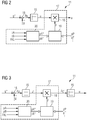
- the controller 11 are according to FIG. 1 First, a target quantity g * related to the piston 3 of the hydraulic cylinder unit 1 and an actual variable g related to the piston 3 of the hydraulic cylinder unit 1 are supplied.
- the desired value g * and the actual size g are typically positions of the piston 3 or forces acting on the piston 3.
- the control device 11 determines based on the target size g * and the actual size g in a manner to be explained a manipulated variable u for the valve control unit 7 and outputs the manipulated variable u to the valve control unit 7.
- the control device 11 thereby performs the control of the hydraulic cylinder unit 1 (more precisely: the piston 3).
- the control device 11 is preferably corresponding FIG. 2 educated. According to FIG. 2
- the control device 11 has a controller 15, which receives on the input side the desired variable g * and the actual variable g.
- the difference ⁇ s of target size g * and actual size g is formed. This difference is referred to below as a control difference ⁇ g.
- the control difference .DELTA.g is supplied to the controller 15, which determines a provisional control variable u 'for the valve control unit 7 on the basis of the control difference .DELTA.g.
- the regulator 15 is corresponding FIG. 2 preferably designed as a P-controller.
- the regulator 15 is followed by a linearization unit 17.
- the linearization unit 17 has a multiplier 18 and a detection device 19.
- the determination means 19 determines, as will be explained, a linearization factor F and outputs the linearization factor F to the multiplier 18.
- the multiplier 18 takes Furthermore, from the controller 15, the preliminary manipulated variable u 'counter and multiplies the provisional manipulated variable u' with the linearization factor F.
- the linearization unit 17 determines in this way a final manipulated variable u, which is output to the valve control unit 7.
- the valve control unit 7 adjusts itself according to the manipulated variable u transmitted to it. This causes the piston 3 is displaced or adjusted or the working pressures pA, pB are set or generally the actual size g of the target size g * is tracked with the adjustment speed.
- the controller 15 can be any controller.
- An embodiment of the controller 15 as a P controller is, however, usually sufficient and also preferred.
- the linearization unit 17 has a setpoint determiner 20.
- the setpoint determiner 20 is supplied with the working pressures pA, pB prevailing on both sides of the piston 3 and a setpoint piston force FKL to be exerted by the piston 3.
- the setpoint determiner 20 determines setpoint values pA *, pB * for the working pressures pA, pB prevailing on both sides of the piston 3 based on the working pressures pA, pB prevailing on both sides of the piston 3 and the setpoint piston force FKL.
- the setpoint determiner 20 supplies the setpoint values pA *, pB * to the determination device 19 for the working pressures pA, pB prevailing on both sides of the piston 3.
- the setpoint determiner 20 determines the setpoint values pA *, pB * for the pistons 3 on both sides Working pressures pA, pB determined solely based on the target piston force FKL and the prevailing on both sides of the piston 3 working pressures pA, pB.
- the setpoint determiner 20 additionally takes into account the working pressures pP, pT prevailing on the inflow and outflow side of the valve control unit 7.
- the determination device 19 determines the linearization factor F dynamically as a function of the actual position s of the piston 3, the setpoints pA *, pB * for the working pressures pA, pB prevailing on both sides of the piston 3 and the working pressures pP, pT prevailing on the inflow and outflow sides of the valve control unit 7.
- the determination device 19 determines the linearization factor F in such a way that a ratio of the adjustment speed of the actual variable g to the difference ⁇ g of the setpoint variable g * and actual variable g is independent of the actual position s of the piston 3, the working pressures pA, pB prevailing on both sides of the piston 3 and the inflow and the discharge side of the valve control unit 7 prevailing working pressures pP, pT.
- the control device 11 is according to FIG. 1 usually clocked with a power stroke T. With the frequency of the power stroke T, the control device 11 each receives a new desired value g * and a new actual variable g, determines the manipulated variable u and outputs the manipulated variable u to the valve control unit 7.
- the determination device 19 also with the power stroke T are the determination device 19 according to FIG. 4 respectively new values for the actual position s and the setpoint values pA *, pB * for the working pressures pA, pB prevailing on both sides of the piston 3 are supplied. Furthermore, the determination device 19 is supplied with the sign of the control difference ⁇ g. The cyclic feeding of this Sizes s, pA, pB, sign ⁇ g is in FIG. 4 indicated that the detection device 19 is a latch 21 upstream, which is clocked with the power stroke T.
- the pump pressure pP and the tank pressure pT are usually constant. It is therefore possible to supply these two pressures pP, pT to the determination device 19 once (ie in advance and therefore as a parameter). Alternatively, it is possible to have the inflow-side working pressure pP and the outflow-side working pressure pT of the determining means 19 as shown in FIG FIG. 4 clocked with the power stroke T and thus supply as a variable.
- the determination device 19 requires further data for the calculation of the linearization factor F.
- the further data generally include performance data pN, QNA, QNB of the valve control unit 7, the working surfaces AKA, AKB effective on both sides of the piston 3 as well as the minimum possible effective volumes VminA, VminB on both sides of the piston 3. These values can be fixedly assigned to the determination device 19, for example by the software module 12. Alternatively, the further data can be predetermined to the determination device 19 after the control device 11 has been programmed as a parameter (ie during the commissioning of the control device 11) be maintained unchanged during operation of the control device 11.
- the determination device 19 preferably calculates both values and selects the correct linearization factor F on the basis of the sign of the control difference ⁇ g.
- FIG. 5 shows a possible embodiment of the control device 11 in the event that the target size g * and the actual size g are the positions or positions s *, s of the piston 3 of the hydraulic cylinder unit 1.
- the adjustment speed of the actual size is the (mechanical) speed with which the piston 3 is displaced.
- the controller 15 acts as a position controller.
- the control device 11 has a force regulator 22, a first speed filter 23, a second speed filter 24 and a delay element 25.
- the position controller 15 is supplied as a desired value g * a target position s *.
- the desired position s * is the position which is to be approached by the piston 3 of the hydraulic cylinder unit 1.
- the position controller 15 is still supplied as the actual size g, the actual position s.
- the controller 15 determines based on the desired position s * and the actual position s a desired speed signal vK *.
- the desired speed signal vK * preferably comprises a proportional component, that is to say a component which is proportional to the control difference ⁇ g. It is possible that the target speed signal vK * exclusively has the proportional component.
- the desired speed signal vK * additionally comprise an integral component and / or a differential component.
- the target speed signal vK * is supplied to the first speed filter 23.
- the desired speed signal vK * is filtered to a filtered speed signal vF.
- the first speed filter 23 is preferably designed so that natural oscillations of the hydraulic system are excited as little as possible. It usually does not have an internal one illustrated delay element - for example, a PT2 member - and further takes into account the required acceleration and friction components that occur in the hydraulic cylinder unit 1.
- a filter characteristic of the first speed filter 23 may be designed as needed.
- S is the Laplace operator.
- a, b, c and d are parameters.
- the speed signal vF filtered by means of the first speed filter 23 is supplied to a node 26 to which a power controller output signal vFC is further supplied.
- the filtered speed signal vF and the power controller output signal vFC are summed at node 26 to form a sum signal.
- the sum signal corresponds to, compared to FIG. 2 and as shown in FIG. 5 , the preliminary manipulated variable u '.
- the procedure according to FIG. 5 May also be based on the design FIG. 3 be applied. In this case, the sum signal corresponds to the manipulated variable u.
- the force regulator 22 is supplied with an expected adjusting force FEV, a piston force FK and an inherent force FE.
- the piston force FK is the force exerted by the hydraulic cylinder unit 1 on the piston 3. It results from the effective piston surfaces AKA, AKB of the piston 3 and the working pressures pA, pB acting on the effective surfaces AKA, AKB.
- the inherent force FE takes into account, in particular, the weight force, which is determined by a dead weight of the mass moved by means of the piston 3.
- the force controller 14 determines based on the expected adjusting force FEV, the piston force FK and the inherent force FE the force controller output signal vFC.
- the force regulator 22 stabilizes the hydraulic system. It is preferably designed as a regulator with differential behavior, so that the power controller output signal vFC becomes zero in the stationary state of the hydraulic cylinder unit 1.
- the expected adjusting force FEV is the force expected due to frictional forces and accelerations. It is determined by the control device 11 based on the output from the controller 15 size vK *. In particular, it is determined by the fact that the setpoint speed signal vK * is first filtered by means of the second speed filter 24 to an adjusting force F 'and then delayed by means of the delay element 25.
- the second speed filter 24 provides as output the sum of acceleration force and friction force.
- a filter characteristic comprising the second velocity filter 16 may be formed as needed for this purpose.
- F ' is the output of the second velocity filter in the above relationship.
- vK * is the setpoint speed signal.
- S is again the Laplace operator.
- e, f, g and h are parameters.
- the delay element 25 serves to simulate the dynamics of the valve control unit 7. This ensures that the output from the delay element 25 signal FEV is synchronized with the piston force FK.
- the delay element 25 may be formed as needed as long as it provides the desired functionality. As a rule, the delay element 25 is designed as a PT2 element.
- the adjusting force F ' is fed to a node 27.
- the node 27 is further attributed the inherent force FE.
- the adjustment force F 'and the inherent force FE are added to the target piston force FKL.
- the control device 11 thus determines the setpoint piston force FKL based on the intrinsic force FE and the adjustment force F '.
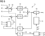
- FIG. 6 shows a possible embodiment of the control device 11 in the event that the target size g * is a target load force FL *.
- the regulator 15 acts as a force regulator.
- an actual load force is regulated as an actual variable g, which the hydraulic cylinder unit 1 exerts on a load via a mechanical system.
- a force acting on the piston 3 piston force FK is - as in the embodiment according to FIG. 5 also - that force which is exerted by the hydraulic cylinder unit 1 on the piston 3. It results from the effective piston surfaces AKA, AKB of the piston 3 and the working pressures pA, pB acting on the effective surfaces AKA, AKB.
- the target load force FL * is the force to be exerted by the piston 3 on a load actuated by the piston 3.
- the controller 15 includes a load controller 28, a force controller 29, a load observer 30 and a delay member 31.
- the load force controller 28 is the target load force FL * and an expected actual load force FL '- ie a calculated value for the actual load force - supplied.
- the expected actual load force FL ' is determined by the load observer 30.
- the load controller 28 regulates the load.
- the load controller 28 determined for this purpose on the basis of the difference between the target load force FL * and expected actual load force FL 'an output signal vLC, hereinafter called load output signal.
- the load controller 28 is usually designed as a P controller or as a PI controller.
- the delay element 31 simulates the dynamics of the valve control unit 7. This ensures that the delayed sum signal VU is synchronized with the piston force FK.
- the delay element 31 can be designed as required, provided that it brings about the functionality just explained. As a rule, the delay element 31 is designed as a PT2 element.
- the force controller 29 is preceded by two nodes 32, 33.
- an intrinsic force FE is added to the target load force FL *.
- the inherent force FE taken into account - as in the embodiment according to FIG. 5 also - in particular the weight, which is determined by a weight of the mass moved by means of the piston 3.
- this sum subtracts the piston force FK.
- the output signal of the node 33 is supplied to the force controller 29.
- the force controller 29 determines an output signal vFC, hereinafter called the force controller output signal.
- the force controller 29 is usually designed as a P-controller or as a PD controller. The force controller 29 stabilizes the control and allows greater dynamics.
- the output signals vLC, vFC of the load controller 28 and the force controller 29 are summed in a node 34 to the temporary manipulated variable u '.
- the preliminary manipulated variable u ' is supplied to the linearization unit 17, which linearizes the provisional manipulated variable u'.
- the linearization unit 17 is arranged directly upstream of the valve control unit 7. It compensates - see the comments on the FIG. 1 . 2 and 4 - Nonlinearities of the hydraulic system.
- the load observer 30 In order for the load observer 30 to be able to determine the expected actual load force FL ', the load observer 30 is supplied with the piston force FK, the inherent force FE and a delayed manipulated variable u "The delayed manipulated variable u" is determined by means of the delay element 31 by delaying the provisional manipulated variable u'.
- the setpoint determiner 20 is according to FIG. 6 as the target piston force FKL the sum of the target load force FL * and inherent force FE is supplied.
- the control device 11 thus determines the setpoint piston force FKL based on the intrinsic force FE and the setpoint FL *.
- the sum of the target load force FL * and the inherent force FE is not fed directly to the setpoint determiner 20, but is previously delayed by means of a delay element 35.
- the delay element 35 simulates the dynamics of the control minus the dynamics of the valve control unit 7. This ensures that the setpoint piston force FKL is synchronized with the piston force FK.
- the delay element 35 may be formed as needed, as long as it effects the functionality just explained. As a rule, the delay element 35 is designed as a PT2 element.
- the load monitor 30 may also be configured as needed.
- the decisive factor is that it simulates the actual load force.
- the load observer 30 thus acts as a corresponding soft sensor which simulates the unmeasured actual load force on the basis of (at least) one measured variable (namely the piston force FK).
- the structure and operation of load monitor 30 are well known to those skilled in the art. There are several ways to implement it that are also known to those skilled in the art. Preferred is an embodiment as shown in the WO 2011/000856 A2 in conjunction with their FIG. 3 is explained.
- One possibility for unambiguously determining the setpoint values pA *, pB * is that the control device 11 determines the setpoint values pA *, pB * for the working pressures pA, pB prevailing on both sides of the piston 3 such that the sum of the setpoint values pA *, pB * is equal to a linear combination of the sum of both sides of the piston 3 prevailing working pressures pA, pB and the sum of the inflow and outflow side of the valve control unit 7 prevailing working pressures pP, pT.
- the setpoint determiner 20 additionally takes into account - or in the case that the Weighting factor ⁇ has the value 0, alternatively - the inflow and outflow side of the valve control unit 7 prevailing working pressures pP, pT.
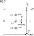
- a possible structure for determining the setpoint values pA *, pB * for the case in which the sum of the setpoint values pA *, pB * is equal to the sum of the working pressures pA, pB prevailing on both sides of the piston 3 is in FIG. 7 shown.
- the structure comprises two multipliers 36, one divider 37 and three nodes 38.
- the multipliers 36 multiply the input signals pA and AKA or pB and AKB supplied to each other.
- the divider 37 divides the input signal supplied to it FKL - pA ⁇ AKA + pB ⁇ AKB through the sum of the effective working areas AKA, AKB.
- the nodes 38 form the sum of the input signals supplied to them. If an input signal is provided with a minus sign, the respective input signal is negative in the sum, so it is subtracted.
- the setpoints pA *, pB * are output at the outputs of the structure.
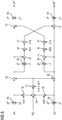
- FIG. 8 shows a further embodiment of FIG. 7 , By means of the embodiment of FIG. 8 It is achieved that the control device 11 limits the setpoint values pA *, pB * for the working pressures pA, pB prevailing on both sides of the piston 3 to values between the working pressures pT, pP prevailing on the inflow and outflow side of the valve control unit 7.
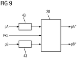
- the setpoint determiner 20 is shown in FIG. 9 Smoothing 43 upstream.
- the smoothing members 43 By means of the smoothing members 43, the working pressures pA, pB are smoothed.
- a smoothing time constant of the smoothing circuits 43 may be between 10 ms and 1000 ms, for example between 30 ms and 300 ms. It has proved to be advantageous in tests to have a value of about 100 ms.
- the invention has been explained above in connection with a hydraulic cylinder unit 1, in which the desired size g * and the actual size g are translational quantities. However, the invention is equally applicable when the target size g * and the actual size g are rotational quantities. In this case, distances must be replaced by appropriate angles and forces replaced by corresponding moments.
- the present invention has many advantages.
- the risk of vibration is significantly reduced, because Although oscillations lead to an antiphase oscillation of the working pressures pA, pB, in the equations for determining the setpoint values pA *, pB * - see in particular the equations 21 and 22 - and thus also the linearization factor SF only the sum of the working pressures pA, pB , The smoothing of the working pressures pA, pB leads to a further calming of the system.
- a regulator 15 accepts a target variable g * related to a piston 3 of the hydraulic cylinder unit 1 and an actual variable g related to the piston 3 of the hydraulic cylinder unit 1. It determines on the basis of their difference ⁇ g a provisional manipulated variable u '.
- a linearization unit 17 arranged downstream of the controller 15 multiplies the provisional manipulated variable u 'by a linearization factor F and outputs the product as the final manipulated variable u to a valve control unit 7, so that the piston 3 of the hydraulic cylinder unit 1 is adjusted at an adjustment speed v.
- the linearization unit 17 determines from both sides of the piston 3 prevailing working pressures pA, pB and / or inflow and outflow side of the valve control unit 7 prevailing working pressures pP, pT and one to be exerted by the piston 3 target piston force FKL setpoints pA *, pB * for the working pressures pA, pB. It determines the linearization factor F dynamically as a function of an actual position s of the piston 3, the setpoint values pA *, pB * and the working pressures pP, pT prevailing on the inflow and outflow side of the valve control unit 7.
Landscapes
- Physics & Mathematics (AREA)
- General Physics & Mathematics (AREA)
- Engineering & Computer Science (AREA)
- Automation & Control Theory (AREA)
- Fluid-Pressure Circuits (AREA)
Claims (12)
- Dispositif de régulation pour la régulation d'un ensemble vérin hydraulique (1),- le dispositif de régulation comprenant un régulateur (15) qui, du côté entrée, reçoit une grandeur théorique (g*) relative à un piston (3) de l'ensemble vérin hydraulique (1) et une grandeur réelle (g) relative au piston (3) de l'ensemble vérin hydraulique (1) et détermine, à l'aide de la différence (8g) entre la grandeur théorique (g*) et la grandeur réelle (g), une grandeur de réglage provisoire (u') pour une unité de commande de soupape (7) de l'ensemble vérin hydraulique (1),- dans lequel une unité de linéarisation (17) est disposée en aval du régulateur (15), laquelle multiplie la grandeur de réglage provisoire (u') par un facteur de linéarisation (F) et est caractérisée en ce qu'elle transmet la grandeur de réglage provisoire (u') multipliée par le facteur de linéarisation (F) en tant que grandeur de réglage définitive (u) à l'unité de commande de soupape (7) de sorte que la grandeur réelle (g) soit amenée à la grandeur théorique (g*) à une vitesse de déplacement,- dans lequel l'unité de linéarisation (17) détermine, à l'aide de pressions de travail (pA, pB) régnant des deux côtés du piston (3) et/ou de pressions de travail (pP, pT) régnant du côté amenée et du côté évacuation de l'unité de commande de soupape (7) ainsi que d'une force de piston théorique (FKL) devant être exercée par le piston (3), des valeurs théoriques (pA*, pB*) pour les pressions de travail (pA, pB) régnant des deux côtés du piston (3),- dans lequel l'unité de linéarisation (17) détermine le facteur de linéarisation (F) dynamiquement en tant que fonction d'une position réelle (s) du piston (3), des valeurs théoriques (pA*, pB*) pour les pressions de travail (pA, pB) régnant des deux côtés du piston (3) ainsi que des pressions de travail (pP, pT) régnant du côté amenée et du côté évacuation de l'unité de commande de soupape (7).
- Dispositif de régulation selon la revendication 1, caractérisé en ce que le régulateur (15) est conçu sous la forme d'un régulateur P.
- Dispositif de régulation pour la régulation d'un ensemble vérin hydraulique (1),- le dispositif de régulation comprenant un régulateur (15) conçu sous la forme d'un régulateur P qui reçoit du côté entrée une grandeur de régulation (8g'), détermine, à l'aide de la grandeur de régulation (δg'), une grandeur de réglage (u) pour une unité de commande de soupape (7) de l'ensemble vérin hydraulique (1) et transmet la grandeur de réglage (u) à l'unité de commande de soupape (7) de sorte qu'une grandeur réelle (g) relative à un piston (3) de l'ensemble vérin hydraulique (1) soit amenée à une grandeur théorique (g*) relative au piston (3) de l'ensemble vérin hydraulique (1) à une vitesse de déplacement,- dans lequel une unité de linéarisation (17) est disposée en amont du régulateur (15), laquelle reçoit la grandeur théorique (g*) et la grandeur réelle (g), multiplie leur différence (8g) par un facteur de linéarisation (F) et transmet la différence (8g) multipliée par le facteur de linéarisation (F) en tant que grandeur de régulation (δg') au régulateur (15), caractérisé en ce que :- dans lequel l'unité de linéarisation (17) détermine, à l'aide de pressions de travail (pA, pB) régnant des deux côtés du piston (3) et/ou de pressions de travail (pP, pT) régnant du côté amenée et du côté évacuation de l'unité de commande de soupape (7) ainsi que d'une force de piston théorique (FKL) devant être exercée par le piston (3), des valeurs théoriques (pA*, pB*) pour les pressions de travail (pA, pB) régnant des deux côtés du piston (3),- dans lequel l'unité de linéarisation (17) détermine le facteur de linéarisation (F) dynamiquement en tant que fonction d'une position réelle (s) du piston (3), des valeurs théoriques (pA*, pB*) pour les pressions de travail (pA, pB) régnant des deux côtés du piston (3) ainsi que des pressions de travail (pP, pT) régnant du côté amenée et du côté évacuation de l'unité de commande de soupape (7).
- Dispositif de régulation selon la revendication 1, la revendication 2 ou la revendication 3,
caractérisé en ce que la grandeur théorique (g*) et la grandeur réelle (g) sont des positions (s*, s) du piston (3) de l'ensemble vérin hydraulique (1) et en ce que le dispositif de régulation détermine la force de piston théorique (FKL) à l'aide d'une force propre (FE) et d'une force de déplacement (F'), en ce que la force propre (FE) est déterminée par l'intermédiaire d'un poids propre d'une masse mise en mouvement au moyen du piston (3) et en ce que le dispositif de régulation détermine la force de déplacement (F') à l'aide d'une grandeur (vK*) fournie par le régulateur (15), à partir de laquelle est déterminée la grandeur de réglage provisoire ou définitive (u', u) par filtrage. - Dispositif de régulation selon la revendication 1, la revendication 2 ou la revendication 3,
caractérisé en ce que la grandeur théorique (g*) est une force de charge théorique (FL*), en ce que la grandeur réelle (g) est une force de charge réelle exercée par l'ensemble vérin hydraulique (1) sur une charge, en ce que le dispositif de régulation détermine la force de piston théorique (FKL) à l'aide d'une force propre (FE) et de la grandeur théorique (g*) et en ce que la force propre (FE) est déterminée par l'intermédiaire d'un poids propre d'une masse mise en mouvement au moyen du piston (3). - Dispositif de régulation selon la revendication 5, caractérisé en ce que le dispositif de régulation détermine, à l'aide de la force propre (FE) et de la grandeur théorique (g*), une valeur théorique de force non temporisée, et en ce que le dispositif de régulation détermine la force de piston théorique (FKL) par temporisation de la valeur théorique de force non temporisée au moyen d'un élément de temporisation (35).
- Dispositif de régulation selon l'une des revendications précédentes,
caractérisé en ce que le dispositif de régulation détermine les valeurs théoriques (pA*, pB*) pour les pressions de travail (pA, pB) régnant des deux côtés du piston (3) de telle sorte que la somme des valeurs théoriques (pA*, pB*) soit égale à une combinaison linéaire de la somme des pressions de travail (pA, pB) régnant des deux côtés du piston (3) et de la somme des pressions de travail (pP, pT) régnant du côté amenée et du côté évacuation de l'unité de commande de soupape (7). - Dispositif de régulation selon l'une des revendications précédentes,
caractérisé en ce que le dispositif de régulation limite les valeurs théoriques (pA*, pB*) pour les pressions de travail (pA, pB) régnant des deux côtés du piston (3) à des valeurs comprises entre les pressions de travail (pT, pP) régnant du côté amenée et du côté évacuation de l'unité de commande de soupape (7). - Dispositif de régulation selon l'une des revendications précédentes,
caractérisé en ce que le dispositif de régulation lisse les pressions de travail (pA, pB) régnant des deux côtés du piston (3) avant la détermination des valeurs théoriques (pA*, pB*) pour les pressions de travail (pA, pB) régnant des deux côtés du piston (3). - Dispositif de régulation selon l'une des revendications précédentes,
caractérisé en ce qu'il est conçu sous la forme d'un dispositif de régulation programmable par logiciel et est programmé avec un module de logiciel (12) de sorte qu'il soit conçu selon l'une des revendications précédentes sur la base de la programmation avec le module de logiciel (12). - Module de logiciel, qui comporte un code machine (14) dont l'exécution par un dispositif de régulation (11) programmable par logiciel relié à un ensemble vérin hydraulique (1) fait que le dispositif de régulation (11) est conçu selon l'une des revendications 1 à 9.
- Module de logiciel selon la revendication 11,
caractérisé en ce qu'il est stocké sous forme lisible par ordinateur sur un support de données (13).
Applications Claiming Priority (2)
| Application Number | Priority Date | Filing Date | Title |
|---|---|---|---|
| EP14165962.3A EP2937746A1 (fr) | 2014-04-25 | 2014-04-25 | Dispositif de réglage de vérin hydraulique à linéarisation optimisée |
| PCT/EP2015/056412 WO2015161979A1 (fr) | 2014-04-25 | 2015-03-25 | Dispositif de régulation destiné à un ensemble vérin hydraulique, à linéarisation améliorée |
Publications (2)
| Publication Number | Publication Date |
|---|---|
| EP3134774A1 EP3134774A1 (fr) | 2017-03-01 |
| EP3134774B1 true EP3134774B1 (fr) | 2018-07-18 |
Family
ID=50555072
Family Applications (2)
| Application Number | Title | Priority Date | Filing Date |
|---|---|---|---|
| EP14165962.3A Withdrawn EP2937746A1 (fr) | 2014-04-25 | 2014-04-25 | Dispositif de réglage de vérin hydraulique à linéarisation optimisée |
| EP15741832.8A Active EP3134774B1 (fr) | 2014-04-25 | 2015-03-25 | Dispositif de réglage de vérin hydraulique à linéarisation optimisée |
Family Applications Before (1)
| Application Number | Title | Priority Date | Filing Date |
|---|---|---|---|
| EP14165962.3A Withdrawn EP2937746A1 (fr) | 2014-04-25 | 2014-04-25 | Dispositif de réglage de vérin hydraulique à linéarisation optimisée |
Country Status (4)
| Country | Link |
|---|---|
| US (1) | US10175659B2 (fr) |
| EP (2) | EP2937746A1 (fr) |
| RU (1) | RU2682121C2 (fr) |
| WO (1) | WO2015161979A1 (fr) |
Families Citing this family (1)
| Publication number | Priority date | Publication date | Assignee | Title |
|---|---|---|---|---|
| RU2748326C1 (ru) * | 2020-02-11 | 2021-05-24 | Федеральное государственное бюджетное образовательное учреждение высшего образования Иркутский государственный университет путей сообщения (ФГБОУ ВО ИрГУПС) | Система и способ управления амплитудой колебаний вибрационной технологической машины |
Family Cites Families (6)
| Publication number | Priority date | Publication date | Assignee | Title |
|---|---|---|---|---|
| EP0557541B1 (fr) * | 1992-02-24 | 1995-10-04 | Siemens Aktiengesellschaft | Régulation à action directe, en particulier pour une cage de laminoir |
| RU2072544C1 (ru) * | 1992-03-11 | 1997-01-27 | Пушин Юрий Николаевич | Электрогидравлический сервопривод |
| US7258058B2 (en) * | 2005-08-31 | 2007-08-21 | Caterpillar Inc | Metering valve with integral relief and makeup function |
| DE102007051857B3 (de) * | 2007-10-30 | 2009-04-23 | Siemens Ag | Regeleinrichtung zum Positionsregeln einer Hydraulikzylindereinheit mit Linearisierungseinheit |
| EP2270613A1 (fr) | 2009-07-03 | 2011-01-05 | Siemens Aktiengesellschaft | Réglage de la force de charge d'une unité de cylindre hydraulique dotée d'un observateur de charge |
| WO2011058616A1 (fr) * | 2009-11-16 | 2011-05-19 | トヨタ自動車株式会社 | Transmission hydraulique |
-
2014
- 2014-04-25 EP EP14165962.3A patent/EP2937746A1/fr not_active Withdrawn
-
2015
- 2015-03-25 RU RU2016141786A patent/RU2682121C2/ru not_active IP Right Cessation
- 2015-03-25 EP EP15741832.8A patent/EP3134774B1/fr active Active
- 2015-03-25 US US15/304,983 patent/US10175659B2/en active Active
- 2015-03-25 WO PCT/EP2015/056412 patent/WO2015161979A1/fr active Application Filing
Non-Patent Citations (1)
| Title |
|---|
| None * |
Also Published As
| Publication number | Publication date |
|---|---|
| RU2016141786A3 (fr) | 2018-09-20 |
| RU2682121C2 (ru) | 2019-03-14 |
| EP2937746A1 (fr) | 2015-10-28 |
| WO2015161979A1 (fr) | 2015-10-29 |
| EP3134774A1 (fr) | 2017-03-01 |
| US10175659B2 (en) | 2019-01-08 |
| RU2016141786A (ru) | 2018-05-25 |
| US20170212481A1 (en) | 2017-07-27 |
Similar Documents
| Publication | Publication Date | Title |
|---|---|---|
| DE102007051857B3 (de) | Regeleinrichtung zum Positionsregeln einer Hydraulikzylindereinheit mit Linearisierungseinheit | |
| EP0515608B1 (fr) | Systeme hydraulique | |
| DE102005031732A1 (de) | Verfahren und Vorrichtung zur Regelung von Pneumatikzylindern | |
| WO2013167248A1 (fr) | Procédé permettant de faire fonctionner une pompe à fluide | |
| EP1886022A1 (fr) | Dispositif de reglage et procede pour le faire fonctionner | |
| DE102017213650A1 (de) | Verfahren zum Regeln eines hydraulischen Systems, Regeleinheit für ein hydraulisches System und hydraulisches System | |
| EP3816455A1 (fr) | Dispositif de commande hydraulique destiné à l'alimentation en fluide de pression d'au moins deux consommateurs hydrauliques | |
| DE2062368C3 (de) | Hydrostatisches Getriebe mit Leistungsbegrenzungssteuer | |
| EP2125258B1 (fr) | Dispositif de réglage pour une cage de laminoir et objets correspondants à cet effet | |
| EP3134774B1 (fr) | Dispositif de réglage de vérin hydraulique à linéarisation optimisée | |
| EP2304515A1 (fr) | Système de commande comprenant une soupape de limitation de pression | |
| DE102016214708A1 (de) | Stetigventileinheit, hydraulische Achse und Verfahren zum Betreiben einer hydraulischen Achse | |
| EP0515639A1 (fr) | Systeme hydraulique. | |
| EP2853752B1 (fr) | Système de régulation | |
| EP2836879B1 (fr) | Dispositif de régulation pour une unité de cylindre hydraulique avec commande séparée de chaque soupape | |
| EP2449436B1 (fr) | Réglage de la force de charge d'une unité de cylindre hydraulique dotée d'un observateur de charge | |
| EP3895819A1 (fr) | Fonctionnement d'un dispositif de réfrigération à une pression de fonctionnement minimale | |
| DE10006977A1 (de) | Regeleinrichtung für einen Hydrotransformator | |
| EP4149805B1 (fr) | Procédé pour réguler la position de pression dans un système de freinage | |
| DE102007050892A1 (de) | Reglerstruktur für eine Hydraulikzylindereinheit mit unterlagertem Zustandsregler | |
| EP3230813B1 (fr) | Procédé d'identification d'une courbe caractéristique | |
| EP2449435B1 (fr) | Dispositif de commande pour une unité de cylindre hydraulique | |
| EP0089058B1 (fr) | Procédé et dispositif pour la régulation d'une variable ainsi qu'application du procédé | |
| EP4115122A1 (fr) | Procédé de régulation du débit et/ou de la pression dans une installation hydraulique | |
| DE102022208574A1 (de) | Verfahren zum Betreiben eines hydraulischen Antriebs einer Maschine und hydraulischer Antrieb |
Legal Events
| Date | Code | Title | Description |
|---|---|---|---|
| STAA | Information on the status of an ep patent application or granted ep patent |
Free format text: STATUS: THE INTERNATIONAL PUBLICATION HAS BEEN MADE |
|
| PUAI | Public reference made under article 153(3) epc to a published international application that has entered the european phase |
Free format text: ORIGINAL CODE: 0009012 |
|
| STAA | Information on the status of an ep patent application or granted ep patent |
Free format text: STATUS: REQUEST FOR EXAMINATION WAS MADE |
|
| 17P | Request for examination filed |
Effective date: 20161125 |
|
| AK | Designated contracting states |
Kind code of ref document: A1 Designated state(s): AL AT BE BG CH CY CZ DE DK EE ES FI FR GB GR HR HU IE IS IT LI LT LU LV MC MK MT NL NO PL PT RO RS SE SI SK SM TR |
|
| AX | Request for extension of the european patent |
Extension state: BA ME |
|
| DAV | Request for validation of the european patent (deleted) | ||
| DAX | Request for extension of the european patent (deleted) | ||
| REG | Reference to a national code |
Ref country code: DE Ref legal event code: R079 Ref document number: 502015005156 Country of ref document: DE Free format text: PREVIOUS MAIN CLASS: G05B0011360000 Ipc: G05D0007060000 |
|
| RIC1 | Information provided on ipc code assigned before grant |
Ipc: G05B 11/36 20060101ALI20171213BHEP Ipc: G05D 7/06 20060101AFI20171213BHEP Ipc: G05B 11/38 20060101ALI20171213BHEP |
|
| GRAP | Despatch of communication of intention to grant a patent |
Free format text: ORIGINAL CODE: EPIDOSNIGR1 |
|
| STAA | Information on the status of an ep patent application or granted ep patent |
Free format text: STATUS: GRANT OF PATENT IS INTENDED |
|
| INTG | Intention to grant announced |
Effective date: 20180316 |
|
| GRAS | Grant fee paid |
Free format text: ORIGINAL CODE: EPIDOSNIGR3 |
|
| GRAA | (expected) grant |
Free format text: ORIGINAL CODE: 0009210 |
|
| STAA | Information on the status of an ep patent application or granted ep patent |
Free format text: STATUS: THE PATENT HAS BEEN GRANTED |
|
| AK | Designated contracting states |
Kind code of ref document: B1 Designated state(s): AL AT BE BG CH CY CZ DE DK EE ES FI FR GB GR HR HU IE IS IT LI LT LU LV MC MK MT NL NO PL PT RO RS SE SI SK SM TR |
|
| REG | Reference to a national code |
Ref country code: GB Ref legal event code: FG4D Free format text: NOT ENGLISH |
|
| REG | Reference to a national code |
Ref country code: CH Ref legal event code: EP |
|
| REG | Reference to a national code |
Ref country code: IE Ref legal event code: FG4D Free format text: LANGUAGE OF EP DOCUMENT: GERMAN |
|
| REG | Reference to a national code |
Ref country code: AT Ref legal event code: REF Ref document number: 1020020 Country of ref document: AT Kind code of ref document: T Effective date: 20180815 |
|
| REG | Reference to a national code |
Ref country code: DE Ref legal event code: R096 Ref document number: 502015005156 Country of ref document: DE |
|
| REG | Reference to a national code |
Ref country code: NL Ref legal event code: MP Effective date: 20180718 |
|
| REG | Reference to a national code |
Ref country code: LT Ref legal event code: MG4D |
|
| PG25 | Lapsed in a contracting state [announced via postgrant information from national office to epo] |
Ref country code: NL Free format text: LAPSE BECAUSE OF FAILURE TO SUBMIT A TRANSLATION OF THE DESCRIPTION OR TO PAY THE FEE WITHIN THE PRESCRIBED TIME-LIMIT Effective date: 20180718 |
|
| PG25 | Lapsed in a contracting state [announced via postgrant information from national office to epo] |
Ref country code: FI Free format text: LAPSE BECAUSE OF FAILURE TO SUBMIT A TRANSLATION OF THE DESCRIPTION OR TO PAY THE FEE WITHIN THE PRESCRIBED TIME-LIMIT Effective date: 20180718 Ref country code: GR Free format text: LAPSE BECAUSE OF FAILURE TO SUBMIT A TRANSLATION OF THE DESCRIPTION OR TO PAY THE FEE WITHIN THE PRESCRIBED TIME-LIMIT Effective date: 20181019 Ref country code: NO Free format text: LAPSE BECAUSE OF FAILURE TO SUBMIT A TRANSLATION OF THE DESCRIPTION OR TO PAY THE FEE WITHIN THE PRESCRIBED TIME-LIMIT Effective date: 20181018 Ref country code: IS Free format text: LAPSE BECAUSE OF FAILURE TO SUBMIT A TRANSLATION OF THE DESCRIPTION OR TO PAY THE FEE WITHIN THE PRESCRIBED TIME-LIMIT Effective date: 20181118 Ref country code: RS Free format text: LAPSE BECAUSE OF FAILURE TO SUBMIT A TRANSLATION OF THE DESCRIPTION OR TO PAY THE FEE WITHIN THE PRESCRIBED TIME-LIMIT Effective date: 20180718 Ref country code: SE Free format text: LAPSE BECAUSE OF FAILURE TO SUBMIT A TRANSLATION OF THE DESCRIPTION OR TO PAY THE FEE WITHIN THE PRESCRIBED TIME-LIMIT Effective date: 20180718 Ref country code: LT Free format text: LAPSE BECAUSE OF FAILURE TO SUBMIT A TRANSLATION OF THE DESCRIPTION OR TO PAY THE FEE WITHIN THE PRESCRIBED TIME-LIMIT Effective date: 20180718 Ref country code: BG Free format text: LAPSE BECAUSE OF FAILURE TO SUBMIT A TRANSLATION OF THE DESCRIPTION OR TO PAY THE FEE WITHIN THE PRESCRIBED TIME-LIMIT Effective date: 20181018 Ref country code: PL Free format text: LAPSE BECAUSE OF FAILURE TO SUBMIT A TRANSLATION OF THE DESCRIPTION OR TO PAY THE FEE WITHIN THE PRESCRIBED TIME-LIMIT Effective date: 20180718 |
|
| PG25 | Lapsed in a contracting state [announced via postgrant information from national office to epo] |
Ref country code: AL Free format text: LAPSE BECAUSE OF FAILURE TO SUBMIT A TRANSLATION OF THE DESCRIPTION OR TO PAY THE FEE WITHIN THE PRESCRIBED TIME-LIMIT Effective date: 20180718 Ref country code: LV Free format text: LAPSE BECAUSE OF FAILURE TO SUBMIT A TRANSLATION OF THE DESCRIPTION OR TO PAY THE FEE WITHIN THE PRESCRIBED TIME-LIMIT Effective date: 20180718 Ref country code: HR Free format text: LAPSE BECAUSE OF FAILURE TO SUBMIT A TRANSLATION OF THE DESCRIPTION OR TO PAY THE FEE WITHIN THE PRESCRIBED TIME-LIMIT Effective date: 20180718 |
|
| REG | Reference to a national code |
Ref country code: DE Ref legal event code: R097 Ref document number: 502015005156 Country of ref document: DE |
|
| PG25 | Lapsed in a contracting state [announced via postgrant information from national office to epo] |
Ref country code: ES Free format text: LAPSE BECAUSE OF FAILURE TO SUBMIT A TRANSLATION OF THE DESCRIPTION OR TO PAY THE FEE WITHIN THE PRESCRIBED TIME-LIMIT Effective date: 20180718 Ref country code: RO Free format text: LAPSE BECAUSE OF FAILURE TO SUBMIT A TRANSLATION OF THE DESCRIPTION OR TO PAY THE FEE WITHIN THE PRESCRIBED TIME-LIMIT Effective date: 20180718 Ref country code: CZ Free format text: LAPSE BECAUSE OF FAILURE TO SUBMIT A TRANSLATION OF THE DESCRIPTION OR TO PAY THE FEE WITHIN THE PRESCRIBED TIME-LIMIT Effective date: 20180718 Ref country code: EE Free format text: LAPSE BECAUSE OF FAILURE TO SUBMIT A TRANSLATION OF THE DESCRIPTION OR TO PAY THE FEE WITHIN THE PRESCRIBED TIME-LIMIT Effective date: 20180718 |
|
| PLBE | No opposition filed within time limit |
Free format text: ORIGINAL CODE: 0009261 |
|
| STAA | Information on the status of an ep patent application or granted ep patent |
Free format text: STATUS: NO OPPOSITION FILED WITHIN TIME LIMIT |
|
| PG25 | Lapsed in a contracting state [announced via postgrant information from national office to epo] |
Ref country code: DK Free format text: LAPSE BECAUSE OF FAILURE TO SUBMIT A TRANSLATION OF THE DESCRIPTION OR TO PAY THE FEE WITHIN THE PRESCRIBED TIME-LIMIT Effective date: 20180718 Ref country code: SM Free format text: LAPSE BECAUSE OF FAILURE TO SUBMIT A TRANSLATION OF THE DESCRIPTION OR TO PAY THE FEE WITHIN THE PRESCRIBED TIME-LIMIT Effective date: 20180718 Ref country code: SK Free format text: LAPSE BECAUSE OF FAILURE TO SUBMIT A TRANSLATION OF THE DESCRIPTION OR TO PAY THE FEE WITHIN THE PRESCRIBED TIME-LIMIT Effective date: 20180718 |
|
| 26N | No opposition filed |
Effective date: 20190423 |
|
| PG25 | Lapsed in a contracting state [announced via postgrant information from national office to epo] |
Ref country code: SI Free format text: LAPSE BECAUSE OF FAILURE TO SUBMIT A TRANSLATION OF THE DESCRIPTION OR TO PAY THE FEE WITHIN THE PRESCRIBED TIME-LIMIT Effective date: 20180718 |
|
| PG25 | Lapsed in a contracting state [announced via postgrant information from national office to epo] |
Ref country code: MC Free format text: LAPSE BECAUSE OF FAILURE TO SUBMIT A TRANSLATION OF THE DESCRIPTION OR TO PAY THE FEE WITHIN THE PRESCRIBED TIME-LIMIT Effective date: 20180718 |
|
| REG | Reference to a national code |
Ref country code: CH Ref legal event code: PL |
|
| GBPC | Gb: european patent ceased through non-payment of renewal fee |
Effective date: 20190325 |
|
| PG25 | Lapsed in a contracting state [announced via postgrant information from national office to epo] |
Ref country code: LU Free format text: LAPSE BECAUSE OF NON-PAYMENT OF DUE FEES Effective date: 20190325 |
|
| REG | Reference to a national code |
Ref country code: BE Ref legal event code: MM Effective date: 20190331 |
|
| PG25 | Lapsed in a contracting state [announced via postgrant information from national office to epo] |
Ref country code: CH Free format text: LAPSE BECAUSE OF NON-PAYMENT OF DUE FEES Effective date: 20190331 Ref country code: LI Free format text: LAPSE BECAUSE OF NON-PAYMENT OF DUE FEES Effective date: 20190331 Ref country code: GB Free format text: LAPSE BECAUSE OF NON-PAYMENT OF DUE FEES Effective date: 20190325 Ref country code: IE Free format text: LAPSE BECAUSE OF NON-PAYMENT OF DUE FEES Effective date: 20190325 |
|
| PG25 | Lapsed in a contracting state [announced via postgrant information from national office to epo] |
Ref country code: FR Free format text: LAPSE BECAUSE OF NON-PAYMENT OF DUE FEES Effective date: 20190331 Ref country code: BE Free format text: LAPSE BECAUSE OF NON-PAYMENT OF DUE FEES Effective date: 20190331 |
|
| PG25 | Lapsed in a contracting state [announced via postgrant information from national office to epo] |
Ref country code: TR Free format text: LAPSE BECAUSE OF FAILURE TO SUBMIT A TRANSLATION OF THE DESCRIPTION OR TO PAY THE FEE WITHIN THE PRESCRIBED TIME-LIMIT Effective date: 20180718 |
|
| PG25 | Lapsed in a contracting state [announced via postgrant information from national office to epo] |
Ref country code: PT Free format text: LAPSE BECAUSE OF FAILURE TO SUBMIT A TRANSLATION OF THE DESCRIPTION OR TO PAY THE FEE WITHIN THE PRESCRIBED TIME-LIMIT Effective date: 20181118 Ref country code: MT Free format text: LAPSE BECAUSE OF FAILURE TO SUBMIT A TRANSLATION OF THE DESCRIPTION OR TO PAY THE FEE WITHIN THE PRESCRIBED TIME-LIMIT Effective date: 20180718 |
|
| REG | Reference to a national code |
Ref country code: DE Ref legal event code: R081 Ref document number: 502015005156 Country of ref document: DE Owner name: PRIMETALS TECHNOLOGIES GERMANY GMBH, DE Free format text: FORMER OWNER: PRIMETALS TECHNOLOGIES GERMANY GMBH, 91052 ERLANGEN, DE |
|
| REG | Reference to a national code |
Ref country code: AT Ref legal event code: MM01 Ref document number: 1020020 Country of ref document: AT Kind code of ref document: T Effective date: 20200325 |
|
| PG25 | Lapsed in a contracting state [announced via postgrant information from national office to epo] |
Ref country code: CY Free format text: LAPSE BECAUSE OF FAILURE TO SUBMIT A TRANSLATION OF THE DESCRIPTION OR TO PAY THE FEE WITHIN THE PRESCRIBED TIME-LIMIT Effective date: 20180718 |
|
| PG25 | Lapsed in a contracting state [announced via postgrant information from national office to epo] |
Ref country code: HU Free format text: LAPSE BECAUSE OF FAILURE TO SUBMIT A TRANSLATION OF THE DESCRIPTION OR TO PAY THE FEE WITHIN THE PRESCRIBED TIME-LIMIT; INVALID AB INITIO Effective date: 20150325 |
|
| PG25 | Lapsed in a contracting state [announced via postgrant information from national office to epo] |
Ref country code: AT Free format text: LAPSE BECAUSE OF NON-PAYMENT OF DUE FEES Effective date: 20200325 |
|
| PG25 | Lapsed in a contracting state [announced via postgrant information from national office to epo] |
Ref country code: MK Free format text: LAPSE BECAUSE OF FAILURE TO SUBMIT A TRANSLATION OF THE DESCRIPTION OR TO PAY THE FEE WITHIN THE PRESCRIBED TIME-LIMIT Effective date: 20180718 |
|
| PGFP | Annual fee paid to national office [announced via postgrant information from national office to epo] |
Ref country code: DE Payment date: 20240320 Year of fee payment: 10 |
|
| PGFP | Annual fee paid to national office [announced via postgrant information from national office to epo] |
Ref country code: IT Payment date: 20240329 Year of fee payment: 10 |