EP2574473A1 - Tintenstrahlaufzeichnungsvorrichtung - Google Patents
Tintenstrahlaufzeichnungsvorrichtung Download PDFInfo
- Publication number
- EP2574473A1 EP2574473A1 EP12005251A EP12005251A EP2574473A1 EP 2574473 A1 EP2574473 A1 EP 2574473A1 EP 12005251 A EP12005251 A EP 12005251A EP 12005251 A EP12005251 A EP 12005251A EP 2574473 A1 EP2574473 A1 EP 2574473A1
- Authority
- EP
- European Patent Office
- Prior art keywords
- ink
- solvent
- container
- route
- recording apparatus
- Prior art date
- Legal status (The legal status is an assumption and is not a legal conclusion. Google has not performed a legal analysis and makes no representation as to the accuracy of the status listed.)
- Granted
Links
Images


Classifications
-
- B—PERFORMING OPERATIONS; TRANSPORTING
- B41—PRINTING; LINING MACHINES; TYPEWRITERS; STAMPS
- B41J—TYPEWRITERS; SELECTIVE PRINTING MECHANISMS, i.e. MECHANISMS PRINTING OTHERWISE THAN FROM A FORME; CORRECTION OF TYPOGRAPHICAL ERRORS
- B41J29/00—Details of, or accessories for, typewriters or selective printing mechanisms not otherwise provided for
- B41J29/377—Cooling or ventilating arrangements
-
- B—PERFORMING OPERATIONS; TRANSPORTING
- B41—PRINTING; LINING MACHINES; TYPEWRITERS; STAMPS
- B41J—TYPEWRITERS; SELECTIVE PRINTING MECHANISMS, i.e. MECHANISMS PRINTING OTHERWISE THAN FROM A FORME; CORRECTION OF TYPOGRAPHICAL ERRORS
- B41J2/00—Typewriters or selective printing mechanisms characterised by the printing or marking process for which they are designed
- B41J2/005—Typewriters or selective printing mechanisms characterised by the printing or marking process for which they are designed characterised by bringing liquid or particles selectively into contact with a printing material
- B41J2/01—Ink jet
- B41J2/015—Ink jet characterised by the jet generation process
- B41J2/02—Ink jet characterised by the jet generation process generating a continuous ink jet
-
- B—PERFORMING OPERATIONS; TRANSPORTING
- B41—PRINTING; LINING MACHINES; TYPEWRITERS; STAMPS
- B41J—TYPEWRITERS; SELECTIVE PRINTING MECHANISMS, i.e. MECHANISMS PRINTING OTHERWISE THAN FROM A FORME; CORRECTION OF TYPOGRAPHICAL ERRORS
- B41J2/00—Typewriters or selective printing mechanisms characterised by the printing or marking process for which they are designed
- B41J2/005—Typewriters or selective printing mechanisms characterised by the printing or marking process for which they are designed characterised by bringing liquid or particles selectively into contact with a printing material
- B41J2/01—Ink jet
- B41J2/17—Ink jet characterised by ink handling
- B41J2/1707—Conditioning of the inside of ink supply circuits, e.g. flushing during start-up or shut-down
-
- B—PERFORMING OPERATIONS; TRANSPORTING
- B41—PRINTING; LINING MACHINES; TYPEWRITERS; STAMPS
- B41J—TYPEWRITERS; SELECTIVE PRINTING MECHANISMS, i.e. MECHANISMS PRINTING OTHERWISE THAN FROM A FORME; CORRECTION OF TYPOGRAPHICAL ERRORS
- B41J2/00—Typewriters or selective printing mechanisms characterised by the printing or marking process for which they are designed
- B41J2/005—Typewriters or selective printing mechanisms characterised by the printing or marking process for which they are designed characterised by bringing liquid or particles selectively into contact with a printing material
- B41J2/01—Ink jet
- B41J2/17—Ink jet characterised by ink handling
- B41J2/1714—Conditioning of the outside of ink supply systems, e.g. inkjet collector cleaning, ink mist removal
-
- B—PERFORMING OPERATIONS; TRANSPORTING
- B41—PRINTING; LINING MACHINES; TYPEWRITERS; STAMPS
- B41J—TYPEWRITERS; SELECTIVE PRINTING MECHANISMS, i.e. MECHANISMS PRINTING OTHERWISE THAN FROM A FORME; CORRECTION OF TYPOGRAPHICAL ERRORS
- B41J2/00—Typewriters or selective printing mechanisms characterised by the printing or marking process for which they are designed
- B41J2/005—Typewriters or selective printing mechanisms characterised by the printing or marking process for which they are designed characterised by bringing liquid or particles selectively into contact with a printing material
- B41J2/01—Ink jet
- B41J2/17—Ink jet characterised by ink handling
- B41J2/18—Ink recirculation systems
- B41J2/185—Ink-collectors; Ink-catchers
-
- B—PERFORMING OPERATIONS; TRANSPORTING
- B41—PRINTING; LINING MACHINES; TYPEWRITERS; STAMPS
- B41J—TYPEWRITERS; SELECTIVE PRINTING MECHANISMS, i.e. MECHANISMS PRINTING OTHERWISE THAN FROM A FORME; CORRECTION OF TYPOGRAPHICAL ERRORS
- B41J2/00—Typewriters or selective printing mechanisms characterised by the printing or marking process for which they are designed
- B41J2/005—Typewriters or selective printing mechanisms characterised by the printing or marking process for which they are designed characterised by bringing liquid or particles selectively into contact with a printing material
- B41J2/01—Ink jet
- B41J2/17—Ink jet characterised by ink handling
- B41J2/195—Ink jet characterised by ink handling for monitoring ink quality
-
- B—PERFORMING OPERATIONS; TRANSPORTING
- B41—PRINTING; LINING MACHINES; TYPEWRITERS; STAMPS
- B41J—TYPEWRITERS; SELECTIVE PRINTING MECHANISMS, i.e. MECHANISMS PRINTING OTHERWISE THAN FROM A FORME; CORRECTION OF TYPOGRAPHICAL ERRORS
- B41J2/00—Typewriters or selective printing mechanisms characterised by the printing or marking process for which they are designed
- B41J2/005—Typewriters or selective printing mechanisms characterised by the printing or marking process for which they are designed characterised by bringing liquid or particles selectively into contact with a printing material
- B41J2/01—Ink jet
- B41J2/17—Ink jet characterised by ink handling
- B41J2/18—Ink recirculation systems
- B41J2/185—Ink-collectors; Ink-catchers
- B41J2002/1853—Ink-collectors; Ink-catchers ink collectors for continuous Inkjet printers, e.g. gutters, mist suction means
Definitions
- the present invention relates to an inkjet recording apparatus that conducts printing by ejecting ink from a nozzle.
- ink is ejected from a nozzle, only ink particles for use in printing are charged by a charging electrode, a flying direction of the charged ink particles is deflected by a deflection electrode to conduct printing.
- Ink particles not used for printing are sucked and recovered into a gutter, and again used for printing.
- circumambient air is also sucked while the ink particles are sucked and recovered.
- the sucked air is discharged from an interior of an ink container toward an exterior thereof because the air is continuously fed into the ink container (for example, refer to Japanese Unexamined Patent Application Publication No. 2009-172932 ).
- ink mist occurs, and the ink mist drifts from the recovery route into the air within the ink container.
- the air within the ink container is discharged from an outlet provided in an inkjet recording apparatus main body toward an exterior of the inkjet recording apparatus main body.
- the ink mist within the ink container is collected into an ink liquid within a route through which the ink mist is discharged to the exterior of the inkjet recording apparatus, and the ink is spilled out of the outlet, resulting in a possibility that the circumference is contaminated with the ink.
- the ink as well as the ink is sucked and pumped into the ink container with the use of a pump located in the recovery route. Thereafter, the ink is accumulated in a lower portion of the ink container, and the air drifts in an upper portion of the ink container. However, the air within the upper portion of the ink container passes through an exhaust route located in the ink container, and is exhausted toward the exterior of the ink container because a fresh air continues to be fed into the ink container from the gutter without interruption.
- a required flow rate of the air is about 80 to 200 [ml/min].
- the flow rate of the air to be sucked from the gutter becomes lower, an ink flow within the gutter becomes slow, and the ink may be spilled from a leading end of the gutter.
- the flow rate of the air to be sucked from the gutter becomes higher, a larger amount of solvent component in the ink is volatilized within the recovery route, and the running costs are increased in order to exhaust the volatilized solvent.
- An object of the present invention is to prevent discharge of the ink mist generated within the recovery route toward the exterior of the device, and the deposition of the ink within the route.
- an inkjet recording apparatus including: an ink container for storing ink which is housed in a main body; a solvent container that accommodates solvent for supplying the solvent to the ink container in order to adjust a concentration of the ink within the ink container; a nozzle that ejects the ink supplied from the ink container through an ink supply channel as ink particles to conduct printing on an object to be printed; a gutter for recovering the ink particles not used for printing among the ink particles ejected by the nozzle; an ink recovery channel for recovering the ink particles recovered by the gutter into the ink container; and a second exhaust channel that discharges a gas recovered together with the ink particles through the ink recover channel from the solvent container to an exterior of the main body, in which the ink container and the solvent container are coupled with each other through a first exhaust channel, an exhaust gas and ink mist within the ink container are supplied to the solvent container through the first exhaust channel, and the solvent container is equipped with an in
- the deposition of the ink mist that flows in the exhaust channels together with the gas within the exhaust routes can be reduced.
- ink contamination of the circumference of the inkjet recording apparatus caused by allowing the ink mist to be discharged to the exterior can be reduced.
- FIG. 1 is a perspective view illustrating an inkjet recording apparatus 100.
- the inkjet recording apparatus 100 includes a main body 1 externally equipped with an operation display unit 3, and a print head 2.
- the main body 1 and the print head 2 are connected to each other by a conducting pipe.
- an ink 7A within an ink container 18 is sucked and pressurized into an ink column 7B by a pump 25, and then ejected from a nozzle 8.
- the nozzle 8 is equipped with an electrostrictive element 9, which subjects the ink to vibration at a given frequency so as to particulate the ink column 7B to be ejected from the nozzle 8.
- the number of ink particles 7C thus generated is determined according to a frequency of an excitation voltage to be applied to the electrostrictive element 9, and have the same number as the frequency.
- the ink particles 7C are given electric charge by applying a voltage having a magnitude corresponding to print information by charging electrodes 11.
- the ink particles 7C charged with the charging electrodes 11 are subject to a force proportional to the amount of electric charge and deflected while flying in an electric field between deflection electrodes 12. Then, the ink particles 7C fly toward an object to be printed 13, and lands thereon. In this situation, a landing position of the ink particles 7C in the deflection direction is changed according to the amount of electric charge, and a production line moves the object to be printed 13 in a direction orthogonal to the deflection direction with the result that the particles can be landed even in the direction orthogonal to the deflection direction, and a character is configured by a plurality of landing particles to conduct printing.
- FIG. 3 An example of actual use forms of the inkjet recording apparatus 100 is illustrated in FIG. 3 .
- the inkjet recording apparatus 100 is installed in the production line within a factory where, for example, foods or beverages are produced.
- the main body 1 is located at a position where a user can operate the main body 1, and the print head 2 is located at a position where the print head 2 can come close to the object to be printed 13 which is fed on the production line such as a belt conveyer 15.
- an encoder 16 that outputs a signal responsive to the feed speed to the inkjet recording apparatus 100, and a print sensor 17 that detects the object to be printed 13, and outputs a signal for ordering printing to the inkjet recording apparatus 100.
- the encoder 16 and the print sensor 17 are connected to a controller not shown within the main body 1.
- the controller controls the amount of electric charge and a charging timing to the ink particles 7C ejected from the nozzle 8 according to signals from the encoder 16 and the print sensor 17, and attaches the charged and deflected ink particles 7C to the object to be printed 13 while the object to be printed 13 is passing through a neighborhood of the print head 2, for conducting printing.
- FIG. 4 is an illustrative view illustrating an overall route configuration of the inkjet recording apparatus 100.
- the main body 1 is equipped with the main ink container 18 that retains a circulating ink therein.
- the main ink container 18 is equipped with a viscosity measurement unit 21 which is a falling ball viscometer for measuring a viscosity of the ink through a route 101 for circulating the ink.
- the viscosity measurement unit 21 is connected to an electromagnetic valve 22 that opens and closes the route through a route 102, and the electromagnetic valve 22 is connected to the pump 25, which contributes to the suction and pumping of the ink and the solvent, through a route 103.
- the pump 25 is connected to a filter 28, which removes foreign material mixed in the ink, through a route 104.
- the filter 28 is connected to a pressure reducing valve 30, which adjusts a pressure of the ink pumped from the pump 25 to a pressure suitable for printing, through a route 105.
- the pressure reducing valve 30 is connected to a pressure sensor 31 for detecting the ink pressure through a route 106.
- the pressure sensor 31 is connected to the nozzle 8 having an ejection port for ejecting the ink, which is disposed within the print head 2, through a route 107 that passes into a conducting pipe 4.
- the charging electrodes 11 that charge ink particles 10 ejected from the nozzle 8 with the amount of electric charge corresponding to character information to be printed are disposed in an ink ejection direction of the nozzle 8.
- Deflection electrodes 12, which develop an electric field for deflecting the charged ink particles 10, are disposed in the flying direction of the ink particles 7C charged by the charging electrodes 11.
- the gutter 14 is connected to a filter 29 for removing the foreign material mixed in the ink, which is arranged within the main body 1, through a route 108 that passes through the conducting pipe 4.
- the filter 29 is connected to a pump 26, which sucks the ink particles 7C trapped by the gutter 14, through a route 109.
- the pump 26 recovers the sucked ink particles 7C into the main ink container 18 through a route 110.
- the main body 1 is equipped with a solvent container 20 that accommodates a solvent 53 for eliminating the ink contamination of the nozzle 8 and adjusting the concentration of the ink.
- the solvent container 20 is connected to a pump 27, which sucks and pumps the solvent, through a route 111.
- the pump 27 is connected to an electromagnetic valve 24, which opens and closes the route, through a route 112, and the electromagnetic valve 24 is connected to the main ink container 18 through a route 113.
- the main body 1 is equipped with an auxiliary ink container 19 that retains a replenishment ink therein, and the auxiliary ink container 19 is connected to an electromagnetic valve 23, which opens and closes the route, through a route 120.
- the electromagnetic valve 23 is connected to the route 103 through a route 121.
- the gutter 14 also sucks a circumambient air while the ink particles 7C are sucked and recovered.
- the sucked air is discharged is fed into the main ink container 18, and discharged from the interior of the main ink container 18 to the exterior of the main body 1 through a route 40.
- the main body 1 is equipped with an outlet 32, and the outlet 32 is connected to a gas portion 44 of the solvent container 20 through a route 45.
- a volatilized solvent component in the ink is exhausted to the exterior of the main body 1 through the route 45.
- a gas portion 80c of the main ink container 18 is connected to a gas exhaust port 60 of the solvent container 20 through a route 41, and the gas exhaust port 60 is arranged in the solvent 53.
- FIG. 8 illustrates a vertically cross-sectional view of the solvent container 20 according to an embodiment of the present invention, which is a cross-sectional view ( FIG. 9 ) taken along a line A-A in FIG. 8 .
- the solvent container 20 includes a solution storage unit 50 that retains the solvent 53 therein, and an upper cover 51 that is disposed on an upper side of the solution storage unit 50.
- the solution storage unit 50 and the upper cover 51 are fixed to each other, for example, with hot plate welding, or screws.
- the upper cover 51 includes a fluid level sensor 52 that detects a fact that a fluid level 53a of the solvent 53 falls below a given value, a pipe (for solvent supply) 111a that is connected to the route 111, a pipe (for exhaust IN) 41a that is connected to the route 41, and a pipe (for exhaust OUT) 45a that is connected to a route 46.
- the pipe (for solvent supply) 111a is configured to have a leading end immersed in the solvent 53.
- the leading end of the pipe (for exhaust OUT) 45a is disposed above the fluid level 53a, and contacts with an exhaust gas 81c.
- the pipe (for exhaust IN) 41a has a leading end connected to the gas exhaust port 60.
- the gas exhaust port 60 is arranged to be immersed in the solvent 53, and designed to discharge an exhaust gas (air bubble) 81d into the solvent 53.
- the solution storage unit 50 is equipped with a partition 50a.
- the provision of the partition 50a makes it possible to prevent the exhaust gas (air bubble) 81d from affecting the detection of the fluid level 53a by the fluid level sensor 52.
- a gap 50b is formed between the partition 50a and one surface of wall surfaces configuring the solution storage unit 50, and the solvent 53 flows into the gap 50b.
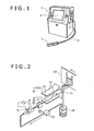
- FIG. 10 illustrates a state in which the fluid level 53a within the solvent container 20 is lowered.
- the fluid level sensor 52 detects a fact that the fluid level 53a is lowered, and issues an alarm for ordering the replenishment ink of the solvent 53. Even in this state, the gas exhaust port 60 is lower than the fluid level 53a, and immersed in the solvent 53.
- the upper cover 51 includes a spout 56 for replenishing the solvent 53, a filter 55 that is arranged in the spout 56 for the purpose of preventing dust from being mixed into the solvent container 20, and a cap 54 that can be opened and closed when replenishing the solvent 53.
- the gas exhaust port 60 includes a body 62 that is connected to the pipe (for exhaust IN) 41a, a base 61 that is disposed below the body 62, a porous component 63 that is installed on an upper portion of the body 62, and a ring 64 and a nut 65 which are disposed to fix the porous component 63.
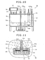
- FIG. 11 Shows in FIG. 11 represent a flow of an exhaust gas 81a.
- the exhaust gas 81a flows together with an ink mist 82a, and at least a part of the ink mist 82a is dissolved in the solvent 53 when the exhaust gas 81a passes through the porous component 63.
- the exhaust gas 81a becomes the exhaust gas (air bubble) 81d when the exhaust gas 81a passes through the porous component 63.
- the exhaust gas (air bubble) 81d goes up within the solvent 53, and joins the exhaust gas (upper portion of solvent container) 81c.
- FIG. 12 is a diagram illustrating the amount of solvent within the solvent container and a change in ink concentration according to the embodiment of the present invention.
- T0 is 0 time of operation
- T1 to T3 are solvent replenishment times
- C0 is ink concentration 0%
- C1 is the ink concentration of the solvent 53 immediately before replenishment
- C2 is the ink concentration of the solvent 53 immediately after replenishment
- V0 is the amount 0 ml of the solvent 53
- V1 is the amount of the solvent 53 immediately before replenishment
- C2 is the amount of the solvent 53 immediately after replenishment.
- the ink concentration of the solvent 53 is not equal to or more than a given value.
- the maximum ink concentration C1 is about 0.01%.
- the ink concentration of the solvent 53 is of the level affecting the apparatus.
- FIG. 5 illustrates a cross-sectional view of the ink recovery route.
- an ink 7d and an air 80b flow together to generate an ink mist 82a.
- FIG. 6 illustrates a cross-sectional view of the route (for exhaust) 41.
- an exhaust gas 81 as well as an ink mist 82a flow.
- FIG. 7 illustrates a cross-sectional view of the route (for exhaust) 45. The route 45 is smaller in the amount of ink mist 81c than the route 41.
- the discharge of the ink mist 81c to the exterior of the apparatus can be reduced, there can be used the inkjet recording apparatus that can keep the clean circumference of the apparatus.
Applications Claiming Priority (1)
| Application Number | Priority Date | Filing Date | Title |
|---|---|---|---|
| JP2011216007A JP5743832B2 (ja) | 2011-09-30 | 2011-09-30 | インクジェット記録装置 |
Publications (2)
| Publication Number | Publication Date |
|---|---|
| EP2574473A1 true EP2574473A1 (de) | 2013-04-03 |
| EP2574473B1 EP2574473B1 (de) | 2015-02-11 |
Family
ID=46581706
Family Applications (1)
| Application Number | Title | Priority Date | Filing Date |
|---|---|---|---|
| EP12005251.9A Not-in-force EP2574473B1 (de) | 2011-09-30 | 2012-07-17 | Tintenstrahlaufzeichnungsvorrichtung |
Country Status (4)
| Country | Link |
|---|---|
| US (1) | US8672449B2 (de) |
| EP (1) | EP2574473B1 (de) |
| JP (1) | JP5743832B2 (de) |
| CN (1) | CN103029432B (de) |
Cited By (7)
| Publication number | Priority date | Publication date | Assignee | Title |
|---|---|---|---|---|
| US9308733B2 (en) | 2014-08-06 | 2016-04-12 | Brother Kogyo Kabushiki Kaisha | Liquid cartridge |
| DE102014224324A1 (de) * | 2014-11-27 | 2016-06-02 | Brother Kogyo Kabushiki Kaisha | Flüssigkeitskartusche |
| US9370933B2 (en) | 2014-08-06 | 2016-06-21 | Brother Kogyo Kabushiki Kaisha | Liquid cartridge |
| US9550367B2 (en) | 2014-08-06 | 2017-01-24 | Brother Kogyo Kabushiki Kaisha | Liquid consuming apparatus |
| EP3210786A1 (de) * | 2016-02-26 | 2017-08-30 | Dover Europe Sàrl | Verfahren und vorrichtung zum hinzufügen von lösungsmittel in kleinen mengen |
| FR3048199A1 (fr) * | 2016-02-26 | 2017-09-01 | Dover Europe Sarl | Dispositif simplifie d'alimentation d'un circuit d'encre |
| CN110626074A (zh) * | 2018-06-21 | 2019-12-31 | 多佛欧洲有限责任公司 | 用于维护喷嘴打印头的方法和设备 |
Families Citing this family (8)
| Publication number | Priority date | Publication date | Assignee | Title |
|---|---|---|---|---|
| US9044954B1 (en) | 2012-05-14 | 2015-06-02 | Videojet Technologies Inc. | Ink jet printer |
| US9227421B2 (en) * | 2012-05-14 | 2016-01-05 | Videojet Technoogies Inc. | Ink jet printer |
| JP5997538B2 (ja) * | 2012-08-07 | 2016-09-28 | 株式会社日立産機システム | インクジェット記録装置 |
| JP5956279B2 (ja) | 2012-08-08 | 2016-07-27 | 株式会社日立産機システム | 気液分離器、及びそれを備えたインクジェット記録装置 |
| CN103448366B (zh) * | 2013-06-27 | 2016-12-28 | 北京大学深圳研究生院 | 一种喷墨打印系统及其应用 |
| CN104924766B (zh) * | 2015-07-08 | 2017-03-01 | 上海美创力罗特维尔电子机械科技有限公司 | 喷码机自动清洗废液再利用方法 |
| US20170144448A1 (en) * | 2015-11-25 | 2017-05-25 | Videojet Technologies, Inc. | Ink quality sensor and a condition monitoring system for an inkjet printer |
| JP6611618B2 (ja) * | 2016-01-08 | 2019-11-27 | キヤノン株式会社 | 記録装置、記録装置の制御方法、及びプログラム |
Citations (3)
| Publication number | Priority date | Publication date | Assignee | Title |
|---|---|---|---|---|
| EP0560332A2 (de) * | 1992-03-12 | 1993-09-15 | Hitachi, Ltd. | Tintenstrahldrucker |
| JP2009172932A (ja) | 2008-01-28 | 2009-08-06 | Hitachi Industrial Equipment Systems Co Ltd | インクジェット記録装置 |
| EP2292433A1 (de) * | 2007-03-27 | 2011-03-09 | Linx Printing Technologies Ltd | Tintenstrahldrucken |
Family Cites Families (11)
| Publication number | Priority date | Publication date | Assignee | Title |
|---|---|---|---|---|
| JPS62141718A (ja) * | 1985-12-17 | 1987-06-25 | Canon Inc | シラン系ガス分解反応による半導体製造における副生粉体除去装置 |
| JPS63183199A (ja) * | 1987-01-26 | 1988-07-28 | Mitsubishi Heavy Ind Ltd | 溶融塩電解メツキ装置の気体塩回収方法 |
| US4811035A (en) * | 1988-03-14 | 1989-03-07 | Eastman Kodak Company | Modular two-color fluid system for continuous ink jet printer |
| US5532720A (en) * | 1993-09-15 | 1996-07-02 | Quad/Tech, Inc. | Solvent recovery system for ink jet printer |
| JP3205674B2 (ja) * | 1994-11-30 | 2001-09-04 | キヤノン株式会社 | 液体噴射装置 |
| JP4544017B2 (ja) * | 2005-03-31 | 2010-09-15 | 株式会社アネモス | 散気処理装置 |
| JP2006346932A (ja) * | 2005-06-14 | 2006-12-28 | Canon Inc | インクジェット記録装置 |
| JP4948146B2 (ja) * | 2006-12-15 | 2012-06-06 | キヤノン株式会社 | インクジェット記録装置 |
| ATE530342T1 (de) * | 2008-01-28 | 2011-11-15 | Hitachi Ind Equipment Sys | Tintenstrahlaufzeichnungsvorrichtung |
| GB2481599B (en) * | 2010-06-29 | 2012-07-18 | Linx Printing Tech | Ink jet printer |
| JP5610880B2 (ja) * | 2010-07-01 | 2014-10-22 | キヤノン株式会社 | インクジェット装置 |
-
2011
- 2011-09-30 JP JP2011216007A patent/JP5743832B2/ja active Active
-
2012
- 2012-07-17 EP EP12005251.9A patent/EP2574473B1/de not_active Not-in-force
- 2012-07-31 US US13/562,475 patent/US8672449B2/en active Active
- 2012-08-06 CN CN201210277661.XA patent/CN103029432B/zh not_active Expired - Fee Related
Patent Citations (3)
| Publication number | Priority date | Publication date | Assignee | Title |
|---|---|---|---|---|
| EP0560332A2 (de) * | 1992-03-12 | 1993-09-15 | Hitachi, Ltd. | Tintenstrahldrucker |
| EP2292433A1 (de) * | 2007-03-27 | 2011-03-09 | Linx Printing Technologies Ltd | Tintenstrahldrucken |
| JP2009172932A (ja) | 2008-01-28 | 2009-08-06 | Hitachi Industrial Equipment Systems Co Ltd | インクジェット記録装置 |
Cited By (10)
| Publication number | Priority date | Publication date | Assignee | Title |
|---|---|---|---|---|
| US9308733B2 (en) | 2014-08-06 | 2016-04-12 | Brother Kogyo Kabushiki Kaisha | Liquid cartridge |
| US9370933B2 (en) | 2014-08-06 | 2016-06-21 | Brother Kogyo Kabushiki Kaisha | Liquid cartridge |
| US9550367B2 (en) | 2014-08-06 | 2017-01-24 | Brother Kogyo Kabushiki Kaisha | Liquid consuming apparatus |
| DE102014224324A1 (de) * | 2014-11-27 | 2016-06-02 | Brother Kogyo Kabushiki Kaisha | Flüssigkeitskartusche |
| EP3210786A1 (de) * | 2016-02-26 | 2017-08-30 | Dover Europe Sàrl | Verfahren und vorrichtung zum hinzufügen von lösungsmittel in kleinen mengen |
| FR3048200A1 (fr) * | 2016-02-26 | 2017-09-01 | Dover Europe Sarl | Procede et dispositif d'ajout de solvant par petites quantites |
| FR3048199A1 (fr) * | 2016-02-26 | 2017-09-01 | Dover Europe Sarl | Dispositif simplifie d'alimentation d'un circuit d'encre |
| US10011119B2 (en) | 2016-02-26 | 2018-07-03 | Dover Europe Sárl | Method and device for adding solvent in small quantities |
| CN110626074A (zh) * | 2018-06-21 | 2019-12-31 | 多佛欧洲有限责任公司 | 用于维护喷嘴打印头的方法和设备 |
| CN110626074B (zh) * | 2018-06-21 | 2022-09-16 | 多佛欧洲有限责任公司 | 用于维护喷嘴打印头的方法和设备 |
Also Published As
| Publication number | Publication date |
|---|---|
| JP5743832B2 (ja) | 2015-07-01 |
| EP2574473B1 (de) | 2015-02-11 |
| US8672449B2 (en) | 2014-03-18 |
| CN103029432A (zh) | 2013-04-10 |
| CN103029432B (zh) | 2015-07-15 |
| JP2013075399A (ja) | 2013-04-25 |
| US20130083124A1 (en) | 2013-04-04 |
Similar Documents
| Publication | Publication Date | Title |
|---|---|---|
| EP2574473B1 (de) | Tintenstrahlaufzeichnungsvorrichtung | |
| JP7413459B2 (ja) | 洗浄装置、及びインクジェット記録装置 | |
| CN100427315C (zh) | 喷墨式记录装置 | |
| JP7326051B2 (ja) | インクジェット記録装置およびインクジェット記録装置の制御方法 | |
| KR100655872B1 (ko) | 유체 제어 밸브 및 액적 토출 장치 | |
| JP6294033B2 (ja) | 液体容器及びそれを備えたインクジェット記録装置 | |
| JP5810656B2 (ja) | 画像形成装置 | |
| EP1700700B1 (de) | Tintenstrahlaufzeichnungsgerät | |
| JP5965860B2 (ja) | インクジェット記録装置 | |
| EP2261037B1 (de) | Filter und Tintenstrahlaufzeichnungsvorrichtung damit | |
| JP5956279B2 (ja) | 気液分離器、及びそれを備えたインクジェット記録装置 | |
| JP2011000861A (ja) | インクジェット記録装置の停止処理方法 | |
| JP4579727B2 (ja) | インクジェット記録装置 | |
| JP2012232447A (ja) | インクジェット記録装置、およびインクジェット記録装置の回復方法 | |
| JP6441729B2 (ja) | インクジェット記録装置およびそれに用いるインク粘度の制御方法 | |
| JP2014065203A (ja) | インクジェット記録装置 | |
| JP6258415B2 (ja) | インクジェット記録装置 | |
| JP6293546B2 (ja) | 液体供給装置および液体吐出装置 | |
| JP6401815B2 (ja) | 気液分離器、及びそれを備えたインクジェット記録装置 | |
| JP2018030232A (ja) | インクジェット記録装置 | |
| JP6130560B2 (ja) | 気液分離器、及びそれを備えたインクジェット記録装置 | |
| JP2006247948A (ja) | 液体噴射装置 | |
| JP2019195910A (ja) | 記録装置 | |
| JP2016068398A (ja) | インクジェット記録装置 |
Legal Events
| Date | Code | Title | Description |
|---|---|---|---|
| PUAI | Public reference made under article 153(3) epc to a published international application that has entered the european phase |
Free format text: ORIGINAL CODE: 0009012 |
|
| 17P | Request for examination filed |
Effective date: 20121115 |
|
| AK | Designated contracting states |
Kind code of ref document: A1 Designated state(s): AL AT BE BG CH CY CZ DE DK EE ES FI FR GB GR HR HU IE IS IT LI LT LU LV MC MK MT NL NO PL PT RO RS SE SI SK SM TR |
|
| AX | Request for extension of the european patent |
Extension state: BA ME |
|
| RBV | Designated contracting states (corrected) |
Designated state(s): AL AT BE BG CH CY CZ DE DK EE ES FI FR GB GR HR HU IE IS IT LI LT LU LV MC MK MT NL NO PL PT RO RS SE SI SK SM TR |
|
| REG | Reference to a national code |
Ref country code: DE Ref legal event code: R079 Ref document number: 602012005193 Country of ref document: DE Free format text: PREVIOUS MAIN CLASS: B41J0002185000 Ipc: B41J0002170000 |
|
| GRAP | Despatch of communication of intention to grant a patent |
Free format text: ORIGINAL CODE: EPIDOSNIGR1 |
|
| RIC1 | Information provided on ipc code assigned before grant |
Ipc: B41J 2/18 20060101ALI20140416BHEP Ipc: B41J 2/17 20060101AFI20140416BHEP Ipc: B41J 2/185 20060101ALI20140416BHEP Ipc: B41J 29/377 20060101ALI20140416BHEP Ipc: B41J 2/02 20060101ALI20140416BHEP Ipc: B41J 2/195 20060101ALI20140416BHEP |
|
| GRAJ | Information related to disapproval of communication of intention to grant by the applicant or resumption of examination proceedings by the epo deleted |
Free format text: ORIGINAL CODE: EPIDOSDIGR1 |
|
| GRAP | Despatch of communication of intention to grant a patent |
Free format text: ORIGINAL CODE: EPIDOSNIGR1 |
|
| INTG | Intention to grant announced |
Effective date: 20140507 |
|
| INTG | Intention to grant announced |
Effective date: 20140603 |
|
| GRAJ | Information related to disapproval of communication of intention to grant by the applicant or resumption of examination proceedings by the epo deleted |
Free format text: ORIGINAL CODE: EPIDOSDIGR1 |
|
| GRAP | Despatch of communication of intention to grant a patent |
Free format text: ORIGINAL CODE: EPIDOSNIGR1 |
|
| INTG | Intention to grant announced |
Effective date: 20140814 |
|
| GRAS | Grant fee paid |
Free format text: ORIGINAL CODE: EPIDOSNIGR3 |
|
| GRAA | (expected) grant |
Free format text: ORIGINAL CODE: 0009210 |
|
| AK | Designated contracting states |
Kind code of ref document: B1 Designated state(s): AL AT BE BG CH CY CZ DE DK EE ES FI FR GB GR HR HU IE IS IT LI LT LU LV MC MK MT NL NO PL PT RO RS SE SI SK SM TR |
|
| REG | Reference to a national code |
Ref country code: GB Ref legal event code: FG4D |
|
| REG | Reference to a national code |
Ref country code: CH Ref legal event code: EP |
|
| REG | Reference to a national code |
Ref country code: IE Ref legal event code: FG4D |
|
| REG | Reference to a national code |
Ref country code: AT Ref legal event code: REF Ref document number: 709780 Country of ref document: AT Kind code of ref document: T Effective date: 20150315 |
|
| REG | Reference to a national code |
Ref country code: DE Ref legal event code: R096 Ref document number: 602012005193 Country of ref document: DE Effective date: 20150326 |
|
| REG | Reference to a national code |
Ref country code: NL Ref legal event code: VDEP Effective date: 20150211 |
|
| REG | Reference to a national code |
Ref country code: AT Ref legal event code: MK05 Ref document number: 709780 Country of ref document: AT Kind code of ref document: T Effective date: 20150211 |
|
| REG | Reference to a national code |
Ref country code: LT Ref legal event code: MG4D |
|
| PG25 | Lapsed in a contracting state [announced via postgrant information from national office to epo] |
Ref country code: FI Free format text: LAPSE BECAUSE OF FAILURE TO SUBMIT A TRANSLATION OF THE DESCRIPTION OR TO PAY THE FEE WITHIN THE PRESCRIBED TIME-LIMIT Effective date: 20150211 Ref country code: ES Free format text: LAPSE BECAUSE OF FAILURE TO SUBMIT A TRANSLATION OF THE DESCRIPTION OR TO PAY THE FEE WITHIN THE PRESCRIBED TIME-LIMIT Effective date: 20150211 Ref country code: LT Free format text: LAPSE BECAUSE OF FAILURE TO SUBMIT A TRANSLATION OF THE DESCRIPTION OR TO PAY THE FEE WITHIN THE PRESCRIBED TIME-LIMIT Effective date: 20150211 Ref country code: NO Free format text: LAPSE BECAUSE OF FAILURE TO SUBMIT A TRANSLATION OF THE DESCRIPTION OR TO PAY THE FEE WITHIN THE PRESCRIBED TIME-LIMIT Effective date: 20150511 Ref country code: HR Free format text: LAPSE BECAUSE OF FAILURE TO SUBMIT A TRANSLATION OF THE DESCRIPTION OR TO PAY THE FEE WITHIN THE PRESCRIBED TIME-LIMIT Effective date: 20150211 Ref country code: SE Free format text: LAPSE BECAUSE OF FAILURE TO SUBMIT A TRANSLATION OF THE DESCRIPTION OR TO PAY THE FEE WITHIN THE PRESCRIBED TIME-LIMIT Effective date: 20150211 |
|
| PG25 | Lapsed in a contracting state [announced via postgrant information from national office to epo] |
Ref country code: LV Free format text: LAPSE BECAUSE OF FAILURE TO SUBMIT A TRANSLATION OF THE DESCRIPTION OR TO PAY THE FEE WITHIN THE PRESCRIBED TIME-LIMIT Effective date: 20150211 Ref country code: IS Free format text: LAPSE BECAUSE OF FAILURE TO SUBMIT A TRANSLATION OF THE DESCRIPTION OR TO PAY THE FEE WITHIN THE PRESCRIBED TIME-LIMIT Effective date: 20150611 Ref country code: AT Free format text: LAPSE BECAUSE OF FAILURE TO SUBMIT A TRANSLATION OF THE DESCRIPTION OR TO PAY THE FEE WITHIN THE PRESCRIBED TIME-LIMIT Effective date: 20150211 Ref country code: NL Free format text: LAPSE BECAUSE OF FAILURE TO SUBMIT A TRANSLATION OF THE DESCRIPTION OR TO PAY THE FEE WITHIN THE PRESCRIBED TIME-LIMIT Effective date: 20150211 Ref country code: RS Free format text: LAPSE BECAUSE OF FAILURE TO SUBMIT A TRANSLATION OF THE DESCRIPTION OR TO PAY THE FEE WITHIN THE PRESCRIBED TIME-LIMIT Effective date: 20150211 Ref country code: GR Free format text: LAPSE BECAUSE OF FAILURE TO SUBMIT A TRANSLATION OF THE DESCRIPTION OR TO PAY THE FEE WITHIN THE PRESCRIBED TIME-LIMIT Effective date: 20150512 |
|
| PG25 | Lapsed in a contracting state [announced via postgrant information from national office to epo] |
Ref country code: SK Free format text: LAPSE BECAUSE OF FAILURE TO SUBMIT A TRANSLATION OF THE DESCRIPTION OR TO PAY THE FEE WITHIN THE PRESCRIBED TIME-LIMIT Effective date: 20150211 Ref country code: DK Free format text: LAPSE BECAUSE OF FAILURE TO SUBMIT A TRANSLATION OF THE DESCRIPTION OR TO PAY THE FEE WITHIN THE PRESCRIBED TIME-LIMIT Effective date: 20150211 Ref country code: RO Free format text: LAPSE BECAUSE OF FAILURE TO SUBMIT A TRANSLATION OF THE DESCRIPTION OR TO PAY THE FEE WITHIN THE PRESCRIBED TIME-LIMIT Effective date: 20150211 Ref country code: CZ Free format text: LAPSE BECAUSE OF FAILURE TO SUBMIT A TRANSLATION OF THE DESCRIPTION OR TO PAY THE FEE WITHIN THE PRESCRIBED TIME-LIMIT Effective date: 20150211 Ref country code: EE Free format text: LAPSE BECAUSE OF FAILURE TO SUBMIT A TRANSLATION OF THE DESCRIPTION OR TO PAY THE FEE WITHIN THE PRESCRIBED TIME-LIMIT Effective date: 20150211 |
|
| REG | Reference to a national code |
Ref country code: DE Ref legal event code: R097 Ref document number: 602012005193 Country of ref document: DE |
|
| PG25 | Lapsed in a contracting state [announced via postgrant information from national office to epo] |
Ref country code: PL Free format text: LAPSE BECAUSE OF FAILURE TO SUBMIT A TRANSLATION OF THE DESCRIPTION OR TO PAY THE FEE WITHIN THE PRESCRIBED TIME-LIMIT Effective date: 20150211 |
|
| PLBE | No opposition filed within time limit |
Free format text: ORIGINAL CODE: 0009261 |
|
| STAA | Information on the status of an ep patent application or granted ep patent |
Free format text: STATUS: NO OPPOSITION FILED WITHIN TIME LIMIT |
|
| PG25 | Lapsed in a contracting state [announced via postgrant information from national office to epo] |
Ref country code: IT Free format text: LAPSE BECAUSE OF FAILURE TO SUBMIT A TRANSLATION OF THE DESCRIPTION OR TO PAY THE FEE WITHIN THE PRESCRIBED TIME-LIMIT Effective date: 20150211 |
|
| 26N | No opposition filed |
Effective date: 20151112 |
|
| PG25 | Lapsed in a contracting state [announced via postgrant information from national office to epo] |
Ref country code: MC Free format text: LAPSE BECAUSE OF FAILURE TO SUBMIT A TRANSLATION OF THE DESCRIPTION OR TO PAY THE FEE WITHIN THE PRESCRIBED TIME-LIMIT Effective date: 20150211 Ref country code: SI Free format text: LAPSE BECAUSE OF FAILURE TO SUBMIT A TRANSLATION OF THE DESCRIPTION OR TO PAY THE FEE WITHIN THE PRESCRIBED TIME-LIMIT Effective date: 20150211 |
|
| REG | Reference to a national code |
Ref country code: CH Ref legal event code: PL |
|
| PG25 | Lapsed in a contracting state [announced via postgrant information from national office to epo] |
Ref country code: LU Free format text: LAPSE BECAUSE OF FAILURE TO SUBMIT A TRANSLATION OF THE DESCRIPTION OR TO PAY THE FEE WITHIN THE PRESCRIBED TIME-LIMIT Effective date: 20150717 |
|
| REG | Reference to a national code |
Ref country code: IE Ref legal event code: MM4A |
|
| PG25 | Lapsed in a contracting state [announced via postgrant information from national office to epo] |
Ref country code: LI Free format text: LAPSE BECAUSE OF NON-PAYMENT OF DUE FEES Effective date: 20150731 Ref country code: CH Free format text: LAPSE BECAUSE OF NON-PAYMENT OF DUE FEES Effective date: 20150731 |
|
| PG25 | Lapsed in a contracting state [announced via postgrant information from national office to epo] |
Ref country code: BE Free format text: LAPSE BECAUSE OF FAILURE TO SUBMIT A TRANSLATION OF THE DESCRIPTION OR TO PAY THE FEE WITHIN THE PRESCRIBED TIME-LIMIT Effective date: 20150211 |
|
| REG | Reference to a national code |
Ref country code: FR Ref legal event code: PLFP Year of fee payment: 5 |
|
| PG25 | Lapsed in a contracting state [announced via postgrant information from national office to epo] |
Ref country code: IE Free format text: LAPSE BECAUSE OF NON-PAYMENT OF DUE FEES Effective date: 20150717 |
|
| PG25 | Lapsed in a contracting state [announced via postgrant information from national office to epo] |
Ref country code: MT Free format text: LAPSE BECAUSE OF FAILURE TO SUBMIT A TRANSLATION OF THE DESCRIPTION OR TO PAY THE FEE WITHIN THE PRESCRIBED TIME-LIMIT Effective date: 20150211 |
|
| PG25 | Lapsed in a contracting state [announced via postgrant information from national office to epo] |
Ref country code: BG Free format text: LAPSE BECAUSE OF FAILURE TO SUBMIT A TRANSLATION OF THE DESCRIPTION OR TO PAY THE FEE WITHIN THE PRESCRIBED TIME-LIMIT Effective date: 20150211 Ref country code: SM Free format text: LAPSE BECAUSE OF FAILURE TO SUBMIT A TRANSLATION OF THE DESCRIPTION OR TO PAY THE FEE WITHIN THE PRESCRIBED TIME-LIMIT Effective date: 20150211 Ref country code: HU Free format text: LAPSE BECAUSE OF FAILURE TO SUBMIT A TRANSLATION OF THE DESCRIPTION OR TO PAY THE FEE WITHIN THE PRESCRIBED TIME-LIMIT; INVALID AB INITIO Effective date: 20120717 |
|
| REG | Reference to a national code |
Ref country code: FR Ref legal event code: PLFP Year of fee payment: 6 |
|
| PG25 | Lapsed in a contracting state [announced via postgrant information from national office to epo] |
Ref country code: CY Free format text: LAPSE BECAUSE OF FAILURE TO SUBMIT A TRANSLATION OF THE DESCRIPTION OR TO PAY THE FEE WITHIN THE PRESCRIBED TIME-LIMIT Effective date: 20150211 |
|
| PG25 | Lapsed in a contracting state [announced via postgrant information from national office to epo] |
Ref country code: TR Free format text: LAPSE BECAUSE OF FAILURE TO SUBMIT A TRANSLATION OF THE DESCRIPTION OR TO PAY THE FEE WITHIN THE PRESCRIBED TIME-LIMIT Effective date: 20150211 |
|
| REG | Reference to a national code |
Ref country code: FR Ref legal event code: PLFP Year of fee payment: 7 |
|
| PG25 | Lapsed in a contracting state [announced via postgrant information from national office to epo] |
Ref country code: MK Free format text: LAPSE BECAUSE OF FAILURE TO SUBMIT A TRANSLATION OF THE DESCRIPTION OR TO PAY THE FEE WITHIN THE PRESCRIBED TIME-LIMIT Effective date: 20150211 Ref country code: PT Free format text: LAPSE BECAUSE OF FAILURE TO SUBMIT A TRANSLATION OF THE DESCRIPTION OR TO PAY THE FEE WITHIN THE PRESCRIBED TIME-LIMIT Effective date: 20150211 |
|
| PG25 | Lapsed in a contracting state [announced via postgrant information from national office to epo] |
Ref country code: AL Free format text: LAPSE BECAUSE OF FAILURE TO SUBMIT A TRANSLATION OF THE DESCRIPTION OR TO PAY THE FEE WITHIN THE PRESCRIBED TIME-LIMIT Effective date: 20150211 |
|
| PGFP | Annual fee paid to national office [announced via postgrant information from national office to epo] |
Ref country code: FR Payment date: 20210611 Year of fee payment: 10 |
|
| PGFP | Annual fee paid to national office [announced via postgrant information from national office to epo] |
Ref country code: GB Payment date: 20210623 Year of fee payment: 10 |
|
| PGFP | Annual fee paid to national office [announced via postgrant information from national office to epo] |
Ref country code: DE Payment date: 20210622 Year of fee payment: 10 |
|
| REG | Reference to a national code |
Ref country code: DE Ref legal event code: R119 Ref document number: 602012005193 Country of ref document: DE |
|
| GBPC | Gb: european patent ceased through non-payment of renewal fee |
Effective date: 20220717 |
|
| PG25 | Lapsed in a contracting state [announced via postgrant information from national office to epo] |
Ref country code: FR Free format text: LAPSE BECAUSE OF NON-PAYMENT OF DUE FEES Effective date: 20220731 |
|
| PG25 | Lapsed in a contracting state [announced via postgrant information from national office to epo] |
Ref country code: GB Free format text: LAPSE BECAUSE OF NON-PAYMENT OF DUE FEES Effective date: 20220717 Ref country code: DE Free format text: LAPSE BECAUSE OF NON-PAYMENT OF DUE FEES Effective date: 20230201 |