EP2573475B1 - Appareil d'aération conçu comme un appareil à induction ainsi que procédé de fonctionnement de cet appareil - Google Patents
Appareil d'aération conçu comme un appareil à induction ainsi que procédé de fonctionnement de cet appareil Download PDFInfo
- Publication number
- EP2573475B1 EP2573475B1 EP12005778.1A EP12005778A EP2573475B1 EP 2573475 B1 EP2573475 B1 EP 2573475B1 EP 12005778 A EP12005778 A EP 12005778A EP 2573475 B1 EP2573475 B1 EP 2573475B1
- Authority
- EP
- European Patent Office
- Prior art keywords
- induction
- air
- nozzles
- group
- same
- Prior art date
- Legal status (The legal status is an assumption and is not a legal conclusion. Google has not performed a legal analysis and makes no representation as to the accuracy of the status listed.)
- Active
Links
- 230000006698 induction Effects 0.000 title claims description 189
- 238000009423 ventilation Methods 0.000 title claims description 19
- 238000000034 method Methods 0.000 title claims description 8
- 230000000694 effects Effects 0.000 claims description 25
- 238000007664 blowing Methods 0.000 claims description 4
- 238000001816 cooling Methods 0.000 description 3
- 238000010438 heat treatment Methods 0.000 description 3
- 230000002349 favourable effect Effects 0.000 description 2
- XLYOFNOQVPJJNP-UHFFFAOYSA-N water Substances O XLYOFNOQVPJJNP-UHFFFAOYSA-N 0.000 description 2
- 238000005352 clarification Methods 0.000 description 1
- 238000006073 displacement reaction Methods 0.000 description 1
- 238000002474 experimental method Methods 0.000 description 1
- 238000003780 insertion Methods 0.000 description 1
- 230000037431 insertion Effects 0.000 description 1
- 238000009434 installation Methods 0.000 description 1
- 230000001105 regulatory effect Effects 0.000 description 1
- 238000011144 upstream manufacturing Methods 0.000 description 1
Images

Classifications
-
- F—MECHANICAL ENGINEERING; LIGHTING; HEATING; WEAPONS; BLASTING
- F24—HEATING; RANGES; VENTILATING
- F24F—AIR-CONDITIONING; AIR-HUMIDIFICATION; VENTILATION; USE OF AIR CURRENTS FOR SCREENING
- F24F1/00—Room units for air-conditioning, e.g. separate or self-contained units or units receiving primary air from a central station
- F24F1/01—Room units for air-conditioning, e.g. separate or self-contained units or units receiving primary air from a central station in which secondary air is induced by injector action of the primary air
-
- F—MECHANICAL ENGINEERING; LIGHTING; HEATING; WEAPONS; BLASTING
- F24—HEATING; RANGES; VENTILATING
- F24F—AIR-CONDITIONING; AIR-HUMIDIFICATION; VENTILATION; USE OF AIR CURRENTS FOR SCREENING
- F24F13/00—Details common to, or for air-conditioning, air-humidification, ventilation or use of air currents for screening
- F24F13/26—Arrangements for air-circulation by means of induction, e.g. by fluid coupling or thermal effect
-
- F—MECHANICAL ENGINEERING; LIGHTING; HEATING; WEAPONS; BLASTING
- F24—HEATING; RANGES; VENTILATING
- F24F—AIR-CONDITIONING; AIR-HUMIDIFICATION; VENTILATION; USE OF AIR CURRENTS FOR SCREENING
- F24F13/00—Details common to, or for air-conditioning, air-humidification, ventilation or use of air currents for screening
- F24F13/02—Ducting arrangements
- F24F13/06—Outlets for directing or distributing air into rooms or spaces, e.g. ceiling air diffuser
- F24F2013/0612—Induction nozzles without swirl means
Definitions
- the invention relates to a ventilation device designed as an induction device, with a plurality of induction nozzles operated with air, in particular with primary air.
- An induction device of the type mentioned is known.
- an induction effect is generated, which means that air, in particular secondary air, is sucked in and mixed with the air blown out of the induction nozzles.
- This mixed air is then preferably used to ventilate a room in a building or the like. If the air sucked in by the induction effect flows through a heat exchanger and/or the mixed air flows through a heat exchanger, the room can be air-conditioned.
- the well-known induction device has several induction nozzles arranged side by side, each of which emits an induction air jet, so that a correspondingly wide zone unfolds an induction effect due to the juxtaposition of the induction nozzles, with the result that, for example, a heat exchanger over its entire width for the passage of secondary air can be used.
- the known induction device has induction nozzles with a relatively large cross section. The result is a relatively high sound pressure level when the known ventilation device is in operation.
- the disclosure document DE 590879C relates to a device for ventilating interior spaces, with air entering the space to be ventilated from nozzles of different sizes.
- the nozzles are arranged in a matrix-like manner at equal distances from one another.
- This publication shows the features of the preamble of claim 1.
- the disclosure document DE 198 26 566 relates to a further device for ventilating a room, in which several induction nozzle arrangements are provided for generating individual jets.
- the object of the invention is to provide an induction device of the type mentioned at the outset that operates relatively quietly with a high induction power.
- the individual induction nozzles of the device according to the invention are preferably designed to be smaller, ie with a smaller cross section.
- the merged induction air jet of a group of induction nozzles according to the invention produces the same or at least approximately the same induction effect as compared to the known induction nozzle of the known device with a larger cross section.
- the sound pressure level of the grouped induction nozzles is lower, so that an induction device is created as a result of the invention, which compared to the known devices with correspondingly comparable Parameters of the conveyed air volume, in particular primary air volume, and at the same pressure of the air that acts on the nozzles, in particular primary air pressure, achieves the same or approximately the same induction effect at a lower sound pressure level.
- the induction nozzles of each group have a smaller distance from one another than the distance between adjacent groups.
- the air jets of the induction nozzles of each group combine to form only one induction air jet, but the induction air jets of the individual groups preferably do not combine.
- each of the groups has three induction nozzles.
- groups of three are formed.
- the induction nozzles of each group are arranged spatially in relation to one another.
- the induction nozzles of each group can lie in a straight line, being positioned in such a direction that the air jets can combine to form the induction air jet, or - as mentioned above - it is provided that they are spatially arranged in relation to one another, e.g. three Induction nozzles are provided in a triangular arrangement, with the result that the air jets then also merge.
- the induction nozzles of a group blow out in the same direction or it is alternatively provided that the blow-out directions of the induction nozzles of a group are different, in particular converge towards one another, although a spatial arrangement of the induction nozzles can be provided.
- the distance between adjacent outlet openings of induction nozzles of the same group is dimension D
- the respective distance between the outlet openings and the associated merging point of the associated air jets is dimension H
- H 1 until 5 ⁇ D .
- the merging point is one to five times as far away from the outlet openings of the associated induction nozzle as the distance from adjacent, associated induction nozzles, with the distance D extending from the center of an induction nozzle to the center of an adjacent induction nozzle.
- a development of the invention provides that the exit angle of the air jet of each induction nozzle of the same group is in the range from 10° to 30°, in particular has a size of 20°.
- At least one induction nozzle of the induction nozzles of at least one group can be opened or closed.
- the arrangement is preferably made in such a way that not all induction nozzles in a group can be opened or closed, but only one or more, but not all, so that a certain induction effect remains and the induction air jet is also generated by merging, i.e. at least two induction nozzles of the same group remain open.
- the "opening or closing" mentioned can also be carried out with intermediate values, ie only a partial one Opening or partial closing.
- a development of the invention provides that the induction nozzle to be opened or closed is further away from a heat exchanger of the induction device than the other induction nozzles of the same group.
- the "other" induction nozzles of the same group are those that cannot be opened or closed. Since—as mentioned—the ventilation device has a heat exchanger that regulates the temperature of the air sucked in by induction, in particular secondary air, the distance of an induction nozzle from the heat exchanger affects the heating or cooling result. In this respect, it is advantageous if an induction nozzle to be closed is further away from the heat exchanger, since the other induction nozzles in this group are then correspondingly closer to the heat exchanger.
- the induction nozzle is opened or closed by means of a slide which interacts with the outlet opening of the induction nozzle.
- This slide can be adjusted automatically, for example, by means of a slide drive. Additionally or alternatively, manual adjustment of the slider is also possible.
- the slide With a control edge, the slide more or less covers the cross section of the outlet opening or releases it or closes it completely.
- the displacement direction of the slide runs transversely, in particular at right angles, to the outflow direction of the air from the induction nozzle.
- the invention also relates to a method for operating a ventilation device designed as an induction device with the features of claim 7, as described above, with several induction nozzles operated with air, in particular with primary air, from which air jets emerge, the air jets of several, one Group or a group forming induction nozzles are formed such that they merge into or into only one induction air jet with each other.
- the method preferably provides for the air jets, which are preferably of the same type and/or preferably of the same size, to be formed from induction nozzles in the same group in such a way that the induction effect of the induction air jet formed is as great or almost as great as the induction effect of a fictitious, single, cross-sectional size, one Fictitious air jet blowing out induction nozzle at the same volume flow of induction air jet of the induction nozzles of this group and fictitious air jet and at the same air pressure, in particular primary air pressure, with which the induction nozzles and the fictitious induction nozzle are supplied.
- the air jets of induction nozzles of the same group which are preferably of the same type and/or preferably of the same size, are formed in such a way that the sound pressure level of these induction nozzles - when a certain conveyed air quantity flows through, in particular primary air quantity - is less than or at most the same as the sound pressure level of one fictitious, single, cross-sectional size induction nozzle blowing out a fictitious air jet with the same conveyed air volume, in particular primary air volume, and with the same volume flow of induction air jet of the induction nozzles of this group and fictitious air jet and/or with the same induction effect of induction air jet and fictitious air jet.
- the induction nozzles according to the invention which have a smaller cross section and are arranged in groups, are compared with a single induction nozzle of the prior art which has a larger cross section and which has a ejects air jet, referred to herein as "fictitious air jet”.
- fictitious air jet a single induction nozzle of the prior art which has a larger cross section and which has a ejects air jet
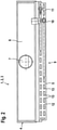
- the figure 1 shows - in longitudinal section - a ventilation device 1, which is designed as an induction device 2, preferably as a ceiling installation device 3. It serves to ventilate and/or air-condition a room in a building or the like.
- a ventilation device 1 which is designed as an induction device 2, preferably as a ceiling installation device 3. It serves to ventilate and/or air-condition a room in a building or the like.
- the device 1 has a housing 4, in which a downwardly open heat exchanger 5, ie not covered by the housing 4 there, is arranged lying. Furthermore, an air distribution box 6 is arranged in the housing 4, which is air-technically connected to a primary air connection piece 7. Opposite the air distribution box 6 is an air outlet 8. Below the heat exchanger 5 is an air inlet 9.
- the heat exchanger 5 has medium connection pieces 10 and 11 in order to be able to conduct a medium, for example warm water or cold water, through the heat exchanger 5.
- the heat exchanger 5 has a multiplicity of heat exchange fins 12, of which—for the sake of simplicity—only heat exchange fins 12 located in a small zone are distinguished, the remaining heat exchange fins 12 are only indicated in a box-like manner.
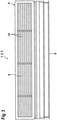
- the figure 2 clarifies the ventilation device 1 in rear view. It can be seen that the air distribution box 6 extends over the entire width of the device and that the primary air connection piece 7 is preferably designed as a round pipe piece.
- the heat exchanger 5 lets in figure 2 Recognize heat exchange tubes 13, which are connected to the medium connection pieces 10 and 11.
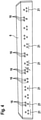
- the figure 3 shows that the air outlet 8 extends essentially over the entire width of the ventilation device 1 and can be provided with air-guiding fins 14 .
- the air distribution box 6 has a wall 15 which lies opposite the air outlet 8 and on which induction nozzles 16 are arranged, in particular formed.
- air in particular primary air
- primary air which is preferably supplied by an air control center in the building or the like via an air distribution network
- This air referred to below as primary air
- This air exits the induction nozzles 16 and generates an induction effect, which means that secondary air, in particular room air, is sucked in through the air inlet 9, which passes through the heat exchanger 5 and is temperature-treated in the process, and then into a mixing chamber 17 gets inside the housing 4, where it is mixed with the primary air emerging from the primary air nozzles 16, the mixed air thus formed being blown through the air outlet 8 into the room.
- the arrow 18 indicates the primary air
- Arrow 19 indicates the secondary air
- arrow 20 indicates the mixed air or supply air.
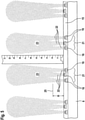
- the figure 4 makes it clear that the mentioned induction nozzles 16 are grouped on the air distribution box 6 .
- Three primary air nozzles 16 each lying on an imaginary triangle form a group 21.
- a large number of groups, thirteen groups 12 in the exemplary embodiment, are arranged at a distance from one another over the length of the air distribution box 6, with the distance between the individual groups 21 being greater than the distance between the Induction nozzles 16 within each group 21 from each other.
- the arrangement of the induction nozzles 16 of each group 21 is spatial, i.e. they are not on a straight line but are arranged on an imaginary triangle, with adjacent groups alternating in the triangular configuration, with either an induction nozzle 16 at the top and two induction nozzles 16 are below, or two induction nozzles 16 are above and one induction nozzle 16 is below.
- the invention assumes that with the same total volume flow and constant admission pressure, different induction nozzle arrangements can be present, namely a few large conventional nozzles (prior art) or many smaller induction nozzles 16, as is the case with the invention.
- many small nozzles are now distributed evenly over the air distribution box 6, but grouped together in such a way that each group 21 of correspondingly small induction nozzles 16 each form only one induction air jet 23, i.e. their air jets 22 merge with this induction air jet 23, the merged induction air jet 23 developing an induction effect that corresponds to that of a larger, known nozzle.
- the sum of the flow noise of the small induction nozzles 16 of several groups 21 is lower than the sum of the flow noise of the large nozzles known from the prior art, the number of which corresponds to the number of groups 21.
- An insertion loss, ie a reduction in the channel noise radiating through, is also more favorable with the smaller induction nozzles 16 according to the invention.
- the positive acoustic properties of the smaller induction nozzles 16 according to the invention come into effect and there is also a positive induction effect that corresponds to the favorable induction effect of large nozzles, in that the smaller induction nozzles 16 are grouped according to the invention, so that the air jets 22 emerging from them form a common one Air jet, namely merge into the mentioned induction air jet 23, so that the effect of this induction air jet 23 corresponds to the effect of a jet from a large nozzle with regard to induction.
- the geometry and arrangement of the individual induction nozzles 16 according to the invention depends on the nozzle size, the primary pressure, the volume flow and the injector length. However, if the person skilled in the art knows the procedure according to the invention, he can he can achieve optimal values through simple experiments.
- the arrangement of the nozzles is as they are from the figure 4 emerges, namely a tripartite grouping provided.
- the upper induction nozzles 16 can be opened or closed. Accordingly, according to figure 4 either one upper induction nozzle 16 per group 21 or two upper induction nozzles are closed, depending on which group is considered.
- the arrangement is preferably such that the opening and closing takes place by means of a slide 26 ( figure 1 ), which is slidably mounted with appropriate means and in the representation of figure 1 takes an open position.
- the slide 26 can be moved back and forth according to the double arrow 27 .
- a motorized device can be provided for this purpose, or it can be moved manually. If the slider 26 is pushed down, it covers the outlet openings 24 of the upper induction nozzles 16 so that no more air jets 22 can exit there.
- the lower row of induction nozzles 16 is not, as in figure 4 once have one and once two induction nozzles 16 per group 21, but there are always at least two induction nozzles 16 present, so that even when the upper row of induction nozzles 16 is covered, an air jet combination can take place.
- the induction nozzles 16 of the upper row are not completely closed, but only partially. In such a case, it is then also permissible that the bottom row in a group 21 only an induction nozzle 16 has.
Landscapes
- Engineering & Computer Science (AREA)
- Chemical & Material Sciences (AREA)
- Combustion & Propulsion (AREA)
- Mechanical Engineering (AREA)
- General Engineering & Computer Science (AREA)
- Jet Pumps And Other Pumps (AREA)
- Ventilation (AREA)
Claims (9)
- Appareil aéraulique conçu comme un appareil à induction, présentant un boîtier (4), avec plusieurs buses d'induction fonctionnant avec de l'air, en particulier avec de l'air primaire, les buses d'induction (16) étant conçues et/ou disposées en groupes, caractérisé en ce que le groupement est tel que des jets d'air (22) sortant des buses d'induction (16) d'un groupe (21) ou de chacun des groupes (21) fusionnent en ou respectivement en un seul jet d'air d'induction (23) à l'intérieur du boîtier (4), chacun des groupes (21) présentant trois buses d'induction (16), les buses d'induction (16) de chaque groupe (21) présentant une distance entre elles inférieure à la distance entre des groupes (21) voisins et la distance respective entre des ouvertures de sortie (24) voisines de buses d'induction (16) du même groupe (21) présentant la dimension D, en ce que la distance respective des ouvertures de sortie (24) jusqu'au point de fusion (25) correspondant des jets d'air (22) correspondants présente la dimension H, et en ce que la relation suivante est valable pour des pressions de buse de 100 à 300 Pa :

- Appareil aéraulique selon la revendication 1, caractérisé en ce que les buses d'induction (16) de chaque groupe (21) sont disposées spatialement les unes par rapport aux autres.
- Appareil aéraulique selon l'une des revendications précédentes, caractérisé en ce que l'angle de sortie du jet d'air de chaque buse d'induction d'un même groupe (21) est compris entre 10° et 30°, et présente notamment une valeur de 20°.
- Appareil aéraulique selon l'une quelconque des revendications précédentes, caractérisé en ce qu'au moins une buse d'induction (16) des buses d'induction (16) d'au moins un groupe (21) peut être ouverte ou fermée.
- Appareil aéraulique selon la revendication précédente, caractérisé en ce que la buse d'induction (16) à ouvrir ou à fermer est plus éloignée d'un échangeur de chaleur (5) de l'appareil à induction (2) que les autres buses d'induction (16) du même groupe (21).
- Appareil aéraulique selon l'une des revendications 4 ou 5 précédentes, caractérisé en ce que l'ouverture ou la fermeture de la buse d'induction (16) est réalisée au moyen d'un tiroir (26) coopérant avec l'ouverture de sortie (24) de la buse d'induction (16).
- Procédé pour faire fonctionner un appareil aéraulique conçu comme un appareil à induction, selon une ou plusieurs des revendications précédentes, avec plusieurs buses d'induction fonctionnant avec de l'air, en particulier avec de l'air primaire, desquelles sortent des jets d'air, caractérisé en ce que les jets d'air (22) sont conçus de plusieurs buses d'induction (16) formant un groupe (21) ou respectivement un groupe (21) de telle sorte qu'ils se fondent les uns dans les autres pour former ou respectivement seulement un jet d'air d'induction (23).
- Procédé selon la revendication 7, caractérisé en ce que les jets d'air (22), de préférence de même type et/ou de préférence de même taille, du même groupe (21) de buses d'induction (16) sont conçus de telle sorte que l'effet d'induction du jet d'air d'induction (23) formé est aussi grand ou presque aussi grand que l'effet d'induction d'une buse d'induction fictive, unique, de section transversale importante, soufflant un jet d'air fictif, pour le même débit volumique de jet d'air d'induction (23) de ce groupe (21) de buses d'induction (16) et de jet d'air fictif et pour la même pression d'air, en particulier la pression d'air primaire, avec laquelle les buses d'induction (16) et la buse d'induction fictive sont alimentées.
- Procédé selon l'une des revendications 7 et 8, caractérisé en ce que les jets d'air (22), de préférence de même type et/ou de préférence de même taille, du même groupe (21) de buses d'induction (16) sont conçus de telle sorte que le niveau de pression acoustique de ces buses d'induction (16) - lors du passage d'un certain débit d'air transporté, en particulier d'un débit d'air primaire - est inférieur ou au maximum égal, que le niveau de pression acoustique d'une buse d'induction fictive, unique, de section transversale importante, soufflant un jet d'air fictif, pour la même quantité d'air transportée, en particulier la quantité d'air primaire, et pour le même débit volumique de jet d'air d'induction (23) de ce groupe (21) de buses d'induction (16) et de jet d'air fictif et/ou pour le même effet d'induction de jet d'air d'induction (23) et de jet d'air fictif.
Applications Claiming Priority (1)
| Application Number | Priority Date | Filing Date | Title |
|---|---|---|---|
| DE102011114335A DE102011114335A1 (de) | 2011-09-21 | 2011-09-21 | Als Induktionsgerät ausgebildetes lufttechnisches Gerät sowie Verfahren zum Betreiben des Geräts |
Publications (3)
| Publication Number | Publication Date |
|---|---|
| EP2573475A2 EP2573475A2 (fr) | 2013-03-27 |
| EP2573475A3 EP2573475A3 (fr) | 2014-06-25 |
| EP2573475B1 true EP2573475B1 (fr) | 2022-01-26 |
Family
ID=46727073
Family Applications (1)
| Application Number | Title | Priority Date | Filing Date |
|---|---|---|---|
| EP12005778.1A Active EP2573475B1 (fr) | 2011-09-21 | 2012-08-09 | Appareil d'aération conçu comme un appareil à induction ainsi que procédé de fonctionnement de cet appareil |
Country Status (2)
| Country | Link |
|---|---|
| EP (1) | EP2573475B1 (fr) |
| DE (1) | DE102011114335A1 (fr) |
Families Citing this family (3)
| Publication number | Priority date | Publication date | Assignee | Title |
|---|---|---|---|---|
| CA2963620A1 (fr) * | 2014-01-16 | 2015-07-23 | Desiccant Rotors International Private Ltd. | Unite de terminal d'air d'apport d'induction presentant un rapport d'induction d'air accru et procede de fourniture d'un rapport d'induction d'air accru |
| KR20160108513A (ko) * | 2014-01-16 | 2016-09-19 | 데시칸트 로터즈 인터내셔널 프라이빗 리미티드 | 증가된 공기 유도율을 가지는 유도급기 단말유니트 및 증가된 공기 유도율을 제공하는 방법 |
| US20210302062A1 (en) * | 2020-03-31 | 2021-09-30 | Tecspec, LLC | Induction unit |
Family Cites Families (5)
| Publication number | Priority date | Publication date | Assignee | Title |
|---|---|---|---|---|
| DE590879C (de) * | 1932-01-20 | 1934-01-12 | Lufttechnische G M B H | Einrichtung zur Belueftung von Innenraeumen jeder Art |
| NL96866C (fr) * | 1954-05-26 | |||
| GB1519770A (en) * | 1974-12-02 | 1978-08-02 | Casaire Ltd | Air conditioning |
| DE19826566C2 (de) * | 1998-06-15 | 2003-05-15 | Ltg Holding Gmbh | Verfahren und Vorrichtung zum Belüften eines Raumes |
| DE10010119A1 (de) * | 2000-03-03 | 2001-09-13 | Krantz Tkt Gmbh | Verfahren und Vorrichtung zur Belüftung und Temperierung eines Raumes |
-
2011
- 2011-09-21 DE DE102011114335A patent/DE102011114335A1/de not_active Ceased
-
2012
- 2012-08-09 EP EP12005778.1A patent/EP2573475B1/fr active Active
Also Published As
| Publication number | Publication date |
|---|---|
| EP2573475A2 (fr) | 2013-03-27 |
| EP2573475A3 (fr) | 2014-06-25 |
| DE102011114335A1 (de) | 2013-03-21 |
Similar Documents
| Publication | Publication Date | Title |
|---|---|---|
| DE10157408A1 (de) | Zuluftvorrichtung | |
| EP3327366B1 (fr) | Sortie d'air permettant le reglage de la temperature d'une chambre | |
| DE102015110559A1 (de) | Luftverteilungssystem für die dritte und/oder vierte Zone eines Drei- oder Vierzonen-Kraftfahrzeugklimagerätes | |
| DE102014107664B4 (de) | Heiz-/klimagerät für kraftfahrzeuge | |
| DE603198C (de) | Einrichtung zur Belueftung und Heizung von Innenraeumen jeder Art | |
| DE102008021015A1 (de) | Vorrichtung zur Mischung von gasförmigen Medien und zum Absperren eines Querschnitts | |
| EP2573475B1 (fr) | Appareil d'aération conçu comme un appareil à induction ainsi que procédé de fonctionnement de cet appareil | |
| DE102017218343A1 (de) | Verfahren zur verteilung von luftventilation in einem fahrzeug | |
| DE2851046A1 (de) | Luftauslassvorrichtung fuer raumklimatisierungs- und belueftungsanlagen | |
| DE2328186C2 (de) | Induktionsgerät | |
| EP3702684A1 (fr) | Climatisation des pièces comprenant une amenée d'air frais et thermorégulation | |
| DE102008016238A1 (de) | Lüftdüse | |
| DE10261036A1 (de) | Klimagehäuse | |
| DE202011004136U1 (de) | Vorrichtung zum Belüften, Heizen und/oder Kühlen eines Raumes | |
| EP3587943B1 (fr) | Dispositif d'aération et de mise en température d'une pièce dans un bâtiment | |
| DE102013111244A1 (de) | Luftauslass | |
| EP3477212B1 (fr) | Dispositif de distribution d'air ainsi que procédé d'aération d'une pièce | |
| DE102008031220A1 (de) | Hybridkühlturm | |
| DE19626884A1 (de) | Luftauslaß | |
| EP1617152A1 (fr) | Procédé et dispositif de ventilation et de climatisation d'un local comprenant une fenêtre | |
| EP1553363B1 (fr) | Ensemble collecteur pour radiateurs de chauffage ou de réfrigeration | |
| DE202011106082U1 (de) | Als Induktionsgerät ausgebildetes lufttechnisches Gerät | |
| CH654901A5 (en) | Device for conditioning the air inside a room | |
| EP2975332B1 (fr) | Système de guidage d'air pour sortie rayonnant et procédé | |
| DE4010134A1 (de) | Luftzufuehrungsvorrichtung fuer die raumklimatisierung |
Legal Events
| Date | Code | Title | Description |
|---|---|---|---|
| PUAI | Public reference made under article 153(3) epc to a published international application that has entered the european phase |
Free format text: ORIGINAL CODE: 0009012 |
|
| AK | Designated contracting states |
Kind code of ref document: A2 Designated state(s): AL AT BE BG CH CY CZ DE DK EE ES FI FR GB GR HR HU IE IS IT LI LT LU LV MC MK MT NL NO PL PT RO RS SE SI SK SM TR |
|
| AX | Request for extension of the european patent |
Extension state: BA ME |
|
| PUAL | Search report despatched |
Free format text: ORIGINAL CODE: 0009013 |
|
| AK | Designated contracting states |
Kind code of ref document: A3 Designated state(s): AL AT BE BG CH CY CZ DE DK EE ES FI FR GB GR HR HU IE IS IT LI LT LU LV MC MK MT NL NO PL PT RO RS SE SI SK SM TR |
|
| AX | Request for extension of the european patent |
Extension state: BA ME |
|
| RIC1 | Information provided on ipc code assigned before grant |
Ipc: F24F 1/01 20110101AFI20140521BHEP Ipc: F24F 13/06 20060101ALI20140521BHEP Ipc: F24F 13/26 20060101ALI20140521BHEP |
|
| 17P | Request for examination filed |
Effective date: 20140903 |
|
| RBV | Designated contracting states (corrected) |
Designated state(s): AL AT BE BG CH CY CZ DE DK EE ES FI FR GB GR HR HU IE IS IT LI LT LU LV MC MK MT NL NO PL PT RO RS SE SI SK SM TR |
|
| STAA | Information on the status of an ep patent application or granted ep patent |
Free format text: STATUS: EXAMINATION IS IN PROGRESS |
|
| 17Q | First examination report despatched |
Effective date: 20180215 |
|
| STAA | Information on the status of an ep patent application or granted ep patent |
Free format text: STATUS: EXAMINATION IS IN PROGRESS |
|
| GRAP | Despatch of communication of intention to grant a patent |
Free format text: ORIGINAL CODE: EPIDOSNIGR1 |
|
| STAA | Information on the status of an ep patent application or granted ep patent |
Free format text: STATUS: GRANT OF PATENT IS INTENDED |
|
| INTG | Intention to grant announced |
Effective date: 20210901 |
|
| GRAS | Grant fee paid |
Free format text: ORIGINAL CODE: EPIDOSNIGR3 |
|
| GRAA | (expected) grant |
Free format text: ORIGINAL CODE: 0009210 |
|
| STAA | Information on the status of an ep patent application or granted ep patent |
Free format text: STATUS: THE PATENT HAS BEEN GRANTED |
|
| AK | Designated contracting states |
Kind code of ref document: B1 Designated state(s): AL AT BE BG CH CY CZ DE DK EE ES FI FR GB GR HR HU IE IS IT LI LT LU LV MC MK MT NL NO PL PT RO RS SE SI SK SM TR |
|
| REG | Reference to a national code |
Ref country code: GB Ref legal event code: FG4D Free format text: NOT ENGLISH |
|
| REG | Reference to a national code |
Ref country code: CH Ref legal event code: EP |
|
| REG | Reference to a national code |
Ref country code: AT Ref legal event code: REF Ref document number: 1465564 Country of ref document: AT Kind code of ref document: T Effective date: 20220215 |
|
| REG | Reference to a national code |
Ref country code: IE Ref legal event code: FG4D Free format text: LANGUAGE OF EP DOCUMENT: GERMAN |
|
| REG | Reference to a national code |
Ref country code: DE Ref legal event code: R096 Ref document number: 502012016977 Country of ref document: DE |
|
| REG | Reference to a national code |
Ref country code: NL Ref legal event code: FP |
|
| REG | Reference to a national code |
Ref country code: LT Ref legal event code: MG9D |
|
| PG25 | Lapsed in a contracting state [announced via postgrant information from national office to epo] |
Ref country code: SE Free format text: LAPSE BECAUSE OF FAILURE TO SUBMIT A TRANSLATION OF THE DESCRIPTION OR TO PAY THE FEE WITHIN THE PRESCRIBED TIME-LIMIT Effective date: 20220126 Ref country code: RS Free format text: LAPSE BECAUSE OF FAILURE TO SUBMIT A TRANSLATION OF THE DESCRIPTION OR TO PAY THE FEE WITHIN THE PRESCRIBED TIME-LIMIT Effective date: 20220126 Ref country code: PT Free format text: LAPSE BECAUSE OF FAILURE TO SUBMIT A TRANSLATION OF THE DESCRIPTION OR TO PAY THE FEE WITHIN THE PRESCRIBED TIME-LIMIT Effective date: 20220526 Ref country code: NO Free format text: LAPSE BECAUSE OF FAILURE TO SUBMIT A TRANSLATION OF THE DESCRIPTION OR TO PAY THE FEE WITHIN THE PRESCRIBED TIME-LIMIT Effective date: 20220426 Ref country code: LT Free format text: LAPSE BECAUSE OF FAILURE TO SUBMIT A TRANSLATION OF THE DESCRIPTION OR TO PAY THE FEE WITHIN THE PRESCRIBED TIME-LIMIT Effective date: 20220126 Ref country code: HR Free format text: LAPSE BECAUSE OF FAILURE TO SUBMIT A TRANSLATION OF THE DESCRIPTION OR TO PAY THE FEE WITHIN THE PRESCRIBED TIME-LIMIT Effective date: 20220126 Ref country code: ES Free format text: LAPSE BECAUSE OF FAILURE TO SUBMIT A TRANSLATION OF THE DESCRIPTION OR TO PAY THE FEE WITHIN THE PRESCRIBED TIME-LIMIT Effective date: 20220126 Ref country code: BG Free format text: LAPSE BECAUSE OF FAILURE TO SUBMIT A TRANSLATION OF THE DESCRIPTION OR TO PAY THE FEE WITHIN THE PRESCRIBED TIME-LIMIT Effective date: 20220426 |
|
| PG25 | Lapsed in a contracting state [announced via postgrant information from national office to epo] |
Ref country code: PL Free format text: LAPSE BECAUSE OF FAILURE TO SUBMIT A TRANSLATION OF THE DESCRIPTION OR TO PAY THE FEE WITHIN THE PRESCRIBED TIME-LIMIT Effective date: 20220126 Ref country code: LV Free format text: LAPSE BECAUSE OF FAILURE TO SUBMIT A TRANSLATION OF THE DESCRIPTION OR TO PAY THE FEE WITHIN THE PRESCRIBED TIME-LIMIT Effective date: 20220126 Ref country code: GR Free format text: LAPSE BECAUSE OF FAILURE TO SUBMIT A TRANSLATION OF THE DESCRIPTION OR TO PAY THE FEE WITHIN THE PRESCRIBED TIME-LIMIT Effective date: 20220427 Ref country code: FI Free format text: LAPSE BECAUSE OF FAILURE TO SUBMIT A TRANSLATION OF THE DESCRIPTION OR TO PAY THE FEE WITHIN THE PRESCRIBED TIME-LIMIT Effective date: 20220126 |
|
| PG25 | Lapsed in a contracting state [announced via postgrant information from national office to epo] |
Ref country code: IS Free format text: LAPSE BECAUSE OF FAILURE TO SUBMIT A TRANSLATION OF THE DESCRIPTION OR TO PAY THE FEE WITHIN THE PRESCRIBED TIME-LIMIT Effective date: 20220526 |
|
| REG | Reference to a national code |
Ref country code: DE Ref legal event code: R097 Ref document number: 502012016977 Country of ref document: DE |
|
| PG25 | Lapsed in a contracting state [announced via postgrant information from national office to epo] |
Ref country code: SM Free format text: LAPSE BECAUSE OF FAILURE TO SUBMIT A TRANSLATION OF THE DESCRIPTION OR TO PAY THE FEE WITHIN THE PRESCRIBED TIME-LIMIT Effective date: 20220126 Ref country code: SK Free format text: LAPSE BECAUSE OF FAILURE TO SUBMIT A TRANSLATION OF THE DESCRIPTION OR TO PAY THE FEE WITHIN THE PRESCRIBED TIME-LIMIT Effective date: 20220126 Ref country code: RO Free format text: LAPSE BECAUSE OF FAILURE TO SUBMIT A TRANSLATION OF THE DESCRIPTION OR TO PAY THE FEE WITHIN THE PRESCRIBED TIME-LIMIT Effective date: 20220126 Ref country code: EE Free format text: LAPSE BECAUSE OF FAILURE TO SUBMIT A TRANSLATION OF THE DESCRIPTION OR TO PAY THE FEE WITHIN THE PRESCRIBED TIME-LIMIT Effective date: 20220126 Ref country code: DK Free format text: LAPSE BECAUSE OF FAILURE TO SUBMIT A TRANSLATION OF THE DESCRIPTION OR TO PAY THE FEE WITHIN THE PRESCRIBED TIME-LIMIT Effective date: 20220126 Ref country code: CZ Free format text: LAPSE BECAUSE OF FAILURE TO SUBMIT A TRANSLATION OF THE DESCRIPTION OR TO PAY THE FEE WITHIN THE PRESCRIBED TIME-LIMIT Effective date: 20220126 |
|
| PG25 | Lapsed in a contracting state [announced via postgrant information from national office to epo] |
Ref country code: AL Free format text: LAPSE BECAUSE OF FAILURE TO SUBMIT A TRANSLATION OF THE DESCRIPTION OR TO PAY THE FEE WITHIN THE PRESCRIBED TIME-LIMIT Effective date: 20220126 |
|
| PLBE | No opposition filed within time limit |
Free format text: ORIGINAL CODE: 0009261 |
|
| STAA | Information on the status of an ep patent application or granted ep patent |
Free format text: STATUS: NO OPPOSITION FILED WITHIN TIME LIMIT |
|
| 26N | No opposition filed |
Effective date: 20221027 |
|
| PG25 | Lapsed in a contracting state [announced via postgrant information from national office to epo] |
Ref country code: SI Free format text: LAPSE BECAUSE OF FAILURE TO SUBMIT A TRANSLATION OF THE DESCRIPTION OR TO PAY THE FEE WITHIN THE PRESCRIBED TIME-LIMIT Effective date: 20220126 |
|
| PG25 | Lapsed in a contracting state [announced via postgrant information from national office to epo] |
Ref country code: MC Free format text: LAPSE BECAUSE OF FAILURE TO SUBMIT A TRANSLATION OF THE DESCRIPTION OR TO PAY THE FEE WITHIN THE PRESCRIBED TIME-LIMIT Effective date: 20220126 |
|
| PG25 | Lapsed in a contracting state [announced via postgrant information from national office to epo] |
Ref country code: IE Free format text: LAPSE BECAUSE OF NON-PAYMENT OF DUE FEES Effective date: 20220809 |
|
| PGFP | Annual fee paid to national office [announced via postgrant information from national office to epo] |
Ref country code: IT Payment date: 20230822 Year of fee payment: 12 Ref country code: GB Payment date: 20230822 Year of fee payment: 12 Ref country code: CH Payment date: 20230902 Year of fee payment: 12 Ref country code: AT Payment date: 20230822 Year of fee payment: 12 |
|
| PGFP | Annual fee paid to national office [announced via postgrant information from national office to epo] |
Ref country code: FR Payment date: 20230824 Year of fee payment: 12 Ref country code: DE Payment date: 20230824 Year of fee payment: 12 Ref country code: BE Payment date: 20230821 Year of fee payment: 12 |
|
| PG25 | Lapsed in a contracting state [announced via postgrant information from national office to epo] |
Ref country code: HU Free format text: LAPSE BECAUSE OF FAILURE TO SUBMIT A TRANSLATION OF THE DESCRIPTION OR TO PAY THE FEE WITHIN THE PRESCRIBED TIME-LIMIT; INVALID AB INITIO Effective date: 20120809 |
|
| PG25 | Lapsed in a contracting state [announced via postgrant information from national office to epo] |
Ref country code: CY Free format text: LAPSE BECAUSE OF FAILURE TO SUBMIT A TRANSLATION OF THE DESCRIPTION OR TO PAY THE FEE WITHIN THE PRESCRIBED TIME-LIMIT Effective date: 20220126 |
|
| PG25 | Lapsed in a contracting state [announced via postgrant information from national office to epo] |
Ref country code: MK Free format text: LAPSE BECAUSE OF FAILURE TO SUBMIT A TRANSLATION OF THE DESCRIPTION OR TO PAY THE FEE WITHIN THE PRESCRIBED TIME-LIMIT Effective date: 20220126 |
|
| PG25 | Lapsed in a contracting state [announced via postgrant information from national office to epo] |
Ref country code: TR Free format text: LAPSE BECAUSE OF FAILURE TO SUBMIT A TRANSLATION OF THE DESCRIPTION OR TO PAY THE FEE WITHIN THE PRESCRIBED TIME-LIMIT Effective date: 20220126 |
|
| PGFP | Annual fee paid to national office [announced via postgrant information from national office to epo] |
Ref country code: LU Payment date: 20240821 Year of fee payment: 13 |
|
| PGFP | Annual fee paid to national office [announced via postgrant information from national office to epo] |
Ref country code: NL Payment date: 20240821 Year of fee payment: 13 |
|
| PG25 | Lapsed in a contracting state [announced via postgrant information from national office to epo] |
Ref country code: MT Free format text: LAPSE BECAUSE OF FAILURE TO SUBMIT A TRANSLATION OF THE DESCRIPTION OR TO PAY THE FEE WITHIN THE PRESCRIBED TIME-LIMIT Effective date: 20220126 |