EP2571419B1 - Wearable ambulatory medical device with multiple sensing electrodes - Google Patents
Wearable ambulatory medical device with multiple sensing electrodes Download PDFInfo
- Publication number
- EP2571419B1 EP2571419B1 EP11784088.4A EP11784088A EP2571419B1 EP 2571419 B1 EP2571419 B1 EP 2571419B1 EP 11784088 A EP11784088 A EP 11784088A EP 2571419 B1 EP2571419 B1 EP 2571419B1
- Authority
- EP
- European Patent Office
- Prior art keywords
- electrodes
- ecg sensing
- sensing electrodes
- electrode
- ecg
- Prior art date
- Legal status (The legal status is an assumption and is not a legal conclusion. Google has not performed a legal analysis and makes no representation as to the accuracy of the status listed.)
- Active
Links
Images


Classifications
-
- A—HUMAN NECESSITIES
- A61—MEDICAL OR VETERINARY SCIENCE; HYGIENE
- A61B—DIAGNOSIS; SURGERY; IDENTIFICATION
- A61B5/00—Measuring for diagnostic purposes; Identification of persons
- A61B5/0002—Remote monitoring of patients using telemetry, e.g. transmission of vital signals via a communication network
- A61B5/0004—Remote monitoring of patients using telemetry, e.g. transmission of vital signals via a communication network characterised by the type of physiological signal transmitted
- A61B5/0006—ECG or EEG signals
-
- A—HUMAN NECESSITIES
- A61—MEDICAL OR VETERINARY SCIENCE; HYGIENE
- A61B—DIAGNOSIS; SURGERY; IDENTIFICATION
- A61B5/00—Measuring for diagnostic purposes; Identification of persons
- A61B5/02—Detecting, measuring or recording for evaluating the cardiovascular system, e.g. pulse, heart rate, blood pressure or blood flow
- A61B5/021—Measuring pressure in heart or blood vessels
-
- A—HUMAN NECESSITIES
- A61—MEDICAL OR VETERINARY SCIENCE; HYGIENE
- A61B—DIAGNOSIS; SURGERY; IDENTIFICATION
- A61B5/00—Measuring for diagnostic purposes; Identification of persons
- A61B5/02—Detecting, measuring or recording for evaluating the cardiovascular system, e.g. pulse, heart rate, blood pressure or blood flow
- A61B5/024—Measuring pulse rate or heart rate
- A61B5/0245—Measuring pulse rate or heart rate by using sensing means generating electric signals, i.e. ECG signals
-
- A—HUMAN NECESSITIES
- A61—MEDICAL OR VETERINARY SCIENCE; HYGIENE
- A61B—DIAGNOSIS; SURGERY; IDENTIFICATION
- A61B5/00—Measuring for diagnostic purposes; Identification of persons
- A61B5/05—Detecting, measuring or recording for diagnosis by means of electric currents or magnetic fields; Measuring using microwaves or radio waves
- A61B5/053—Measuring electrical impedance or conductance of a portion of the body
-
- A—HUMAN NECESSITIES
- A61—MEDICAL OR VETERINARY SCIENCE; HYGIENE
- A61B—DIAGNOSIS; SURGERY; IDENTIFICATION
- A61B5/00—Measuring for diagnostic purposes; Identification of persons
- A61B5/08—Measuring devices for evaluating the respiratory organs
- A61B5/0816—Measuring devices for examining respiratory frequency
-
- A—HUMAN NECESSITIES
- A61—MEDICAL OR VETERINARY SCIENCE; HYGIENE
- A61B—DIAGNOSIS; SURGERY; IDENTIFICATION
- A61B5/00—Measuring for diagnostic purposes; Identification of persons
- A61B5/103—Measuring devices for testing the shape, pattern, colour, size or movement of the body or parts thereof, for diagnostic purposes
- A61B5/11—Measuring movement of the entire body or parts thereof, e.g. head or hand tremor or mobility of a limb
- A61B5/1118—Determining activity level
-
- A—HUMAN NECESSITIES
- A61—MEDICAL OR VETERINARY SCIENCE; HYGIENE
- A61B—DIAGNOSIS; SURGERY; IDENTIFICATION
- A61B5/00—Measuring for diagnostic purposes; Identification of persons
- A61B5/145—Measuring characteristics of blood in vivo, e.g. gas concentration or pH-value ; Measuring characteristics of body fluids or tissues, e.g. interstitial fluid or cerebral tissue
- A61B5/14542—Measuring characteristics of blood in vivo, e.g. gas concentration or pH-value ; Measuring characteristics of body fluids or tissues, e.g. interstitial fluid or cerebral tissue for measuring blood gases
-
- A—HUMAN NECESSITIES
- A61—MEDICAL OR VETERINARY SCIENCE; HYGIENE
- A61B—DIAGNOSIS; SURGERY; IDENTIFICATION
- A61B5/00—Measuring for diagnostic purposes; Identification of persons
- A61B5/24—Detecting, measuring or recording bioelectric or biomagnetic signals of the body or parts thereof
- A61B5/25—Bioelectric electrodes therefor
- A61B5/279—Bioelectric electrodes therefor specially adapted for particular uses
- A61B5/28—Bioelectric electrodes therefor specially adapted for particular uses for electrocardiography [ECG]
- A61B5/282—Holders for multiple electrodes
-
- A—HUMAN NECESSITIES
- A61—MEDICAL OR VETERINARY SCIENCE; HYGIENE
- A61B—DIAGNOSIS; SURGERY; IDENTIFICATION
- A61B5/00—Measuring for diagnostic purposes; Identification of persons
- A61B5/24—Detecting, measuring or recording bioelectric or biomagnetic signals of the body or parts thereof
- A61B5/316—Modalities, i.e. specific diagnostic methods
- A61B5/318—Heart-related electrical modalities, e.g. electrocardiography [ECG]
- A61B5/346—Analysis of electrocardiograms
- A61B5/349—Detecting specific parameters of the electrocardiograph cycle
- A61B5/35—Detecting specific parameters of the electrocardiograph cycle by template matching
-
- A—HUMAN NECESSITIES
- A61—MEDICAL OR VETERINARY SCIENCE; HYGIENE
- A61B—DIAGNOSIS; SURGERY; IDENTIFICATION
- A61B5/00—Measuring for diagnostic purposes; Identification of persons
- A61B5/24—Detecting, measuring or recording bioelectric or biomagnetic signals of the body or parts thereof
- A61B5/316—Modalities, i.e. specific diagnostic methods
- A61B5/318—Heart-related electrical modalities, e.g. electrocardiography [ECG]
- A61B5/346—Analysis of electrocardiograms
- A61B5/349—Detecting specific parameters of the electrocardiograph cycle
- A61B5/364—Detecting abnormal ECG interval, e.g. extrasystoles, ectopic heartbeats
-
- A—HUMAN NECESSITIES
- A61—MEDICAL OR VETERINARY SCIENCE; HYGIENE
- A61B—DIAGNOSIS; SURGERY; IDENTIFICATION
- A61B5/00—Measuring for diagnostic purposes; Identification of persons
- A61B5/48—Other medical applications
- A61B5/4836—Diagnosis combined with treatment in closed-loop systems or methods
-
- A—HUMAN NECESSITIES
- A61—MEDICAL OR VETERINARY SCIENCE; HYGIENE
- A61B—DIAGNOSIS; SURGERY; IDENTIFICATION
- A61B5/00—Measuring for diagnostic purposes; Identification of persons
- A61B5/68—Arrangements of detecting, measuring or recording means, e.g. sensors, in relation to patient
- A61B5/6801—Arrangements of detecting, measuring or recording means, e.g. sensors, in relation to patient specially adapted to be attached to or worn on the body surface
- A61B5/6802—Sensor mounted on worn items
- A61B5/6804—Garments; Clothes
- A61B5/6805—Vests, e.g. shirts or gowns
-
- A—HUMAN NECESSITIES
- A61—MEDICAL OR VETERINARY SCIENCE; HYGIENE
- A61B—DIAGNOSIS; SURGERY; IDENTIFICATION
- A61B5/00—Measuring for diagnostic purposes; Identification of persons
- A61B5/68—Arrangements of detecting, measuring or recording means, e.g. sensors, in relation to patient
- A61B5/6801—Arrangements of detecting, measuring or recording means, e.g. sensors, in relation to patient specially adapted to be attached to or worn on the body surface
- A61B5/6813—Specially adapted to be attached to a specific body part
- A61B5/6823—Trunk, e.g., chest, back, abdomen, hip
-
- A—HUMAN NECESSITIES
- A61—MEDICAL OR VETERINARY SCIENCE; HYGIENE
- A61B—DIAGNOSIS; SURGERY; IDENTIFICATION
- A61B5/00—Measuring for diagnostic purposes; Identification of persons
- A61B5/72—Signal processing specially adapted for physiological signals or for diagnostic purposes
- A61B5/7203—Signal processing specially adapted for physiological signals or for diagnostic purposes for noise prevention, reduction or removal
- A61B5/7207—Signal processing specially adapted for physiological signals or for diagnostic purposes for noise prevention, reduction or removal of noise induced by motion artifacts
-
- A—HUMAN NECESSITIES
- A61—MEDICAL OR VETERINARY SCIENCE; HYGIENE
- A61B—DIAGNOSIS; SURGERY; IDENTIFICATION
- A61B5/00—Measuring for diagnostic purposes; Identification of persons
- A61B5/72—Signal processing specially adapted for physiological signals or for diagnostic purposes
- A61B5/7221—Determining signal validity, reliability or quality
-
- A—HUMAN NECESSITIES
- A61—MEDICAL OR VETERINARY SCIENCE; HYGIENE
- A61N—ELECTROTHERAPY; MAGNETOTHERAPY; RADIATION THERAPY; ULTRASOUND THERAPY
- A61N1/00—Electrotherapy; Circuits therefor
- A61N1/02—Details
- A61N1/04—Electrodes
- A61N1/0404—Electrodes for external use
- A61N1/0408—Use-related aspects
- A61N1/046—Specially adapted for shock therapy, e.g. defibrillation
-
- A—HUMAN NECESSITIES
- A61—MEDICAL OR VETERINARY SCIENCE; HYGIENE
- A61N—ELECTROTHERAPY; MAGNETOTHERAPY; RADIATION THERAPY; ULTRASOUND THERAPY
- A61N1/00—Electrotherapy; Circuits therefor
- A61N1/02—Details
- A61N1/04—Electrodes
- A61N1/0404—Electrodes for external use
- A61N1/0472—Structure-related aspects
- A61N1/0484—Garment electrodes worn by the patient
-
- A—HUMAN NECESSITIES
- A61—MEDICAL OR VETERINARY SCIENCE; HYGIENE
- A61N—ELECTROTHERAPY; MAGNETOTHERAPY; RADIATION THERAPY; ULTRASOUND THERAPY
- A61N1/00—Electrotherapy; Circuits therefor
- A61N1/18—Applying electric currents by contact electrodes
- A61N1/32—Applying electric currents by contact electrodes alternating or intermittent currents
- A61N1/38—Applying electric currents by contact electrodes alternating or intermittent currents for producing shock effects
- A61N1/39—Heart defibrillators
- A61N1/3987—Heart defibrillators characterised by the timing or triggering of the shock
-
- A—HUMAN NECESSITIES
- A61—MEDICAL OR VETERINARY SCIENCE; HYGIENE
- A61B—DIAGNOSIS; SURGERY; IDENTIFICATION
- A61B2562/00—Details of sensors; Constructional details of sensor housings or probes; Accessories for sensors
- A61B2562/04—Arrangements of multiple sensors of the same type
-
- A—HUMAN NECESSITIES
- A61—MEDICAL OR VETERINARY SCIENCE; HYGIENE
- A61N—ELECTROTHERAPY; MAGNETOTHERAPY; RADIATION THERAPY; ULTRASOUND THERAPY
- A61N1/00—Electrotherapy; Circuits therefor
- A61N1/18—Applying electric currents by contact electrodes
- A61N1/32—Applying electric currents by contact electrodes alternating or intermittent currents
- A61N1/38—Applying electric currents by contact electrodes alternating or intermittent currents for producing shock effects
- A61N1/39—Heart defibrillators
- A61N1/3904—External heart defibrillators [EHD]
Definitions
- the present invention is generally directed to the detection of cardiac function in a patient, and more particularly to the detection of cardiac function and the treatment of cardiac conditions in an ambulatory medical device, such as a wearable defibrillator.
- the patient's electrocardiogram (ECG) signal is obtained from body surface electrodes.
- ECG electrocardiogram
- electrical noise or electrode fall-off frequently degrades the quality of the ECG signal.
- the challenge becomes one of extracting a clean ECG signal from the sometimes noisy signals derived from the body-surface electrodes.
- Electrode noise can be caused by electrodes sliding on the patient's body due to extreme patient movement, such as vigorous exercise. Noise can also be caused by a poorly fit electrode belt or garment allowing the electrodes to slide on the patient's body with minor patient movement. Electrode fall-off can be caused by the electrodes flipping over and losing contact with the body, or lifting from the body and losing contact. Even where the electrodes are properly positioned on the patient's body, excessively dry skin can also cause noise.
- Known ambulatory wearable defibrillators such as the LifeVest® Wearable Cardioverter Defibrillator available from Zoll Medical Corporation of Chelmsford, Massachusetts, use four ECG sensing electrodes in a dual-channel configuration. That is, an electrical signal provided by one of the four ECG sensing electrodes is paired with the electrical signal provided by another of the four ECG sensing electrodes to form a channel.
- This arrangement of ECG sensing electrodes is usually suitable because in most cases it is rare that noise or electrode movement affects the entire body circumference.
- the dual-channel configuration provides redundancy and allows the system to operate on a single channel if necessary, when one of the channels is declared unusable due to ECG sensing electrode fall-off, or to an inferior signal-to-noise ratio. Because signal quality also varies from patient to patient, having two channels provides the opportunity to have improved signal pickup, since the ECG sensing electrodes are located in different body positions. The two channel system also allows analysis of the ECG signal to determine cardiac conditions as described in U.S. Patent No. 5,944,669 . Furthermore, US 2010/0041975 A1 discloses patient monitoring systems and methods. US 5,184,620 discloses a method of using a multiple electrode pad assembly and US 2006/0178706 A1 discloses monitoring physiological signals during external electrical stimulation.
- Embodiments of the present invention are directed to a wearable medical monitoring device and/or to a wearable medical monitoring and treatment device that incorporates multiple ECG sensing electrodes disposed at different axial positions around the body of a patient and that can choose from multiple channels corresponding to different pairings of those multiple ECG sensing electrodes to vastly improve the quality of the ECG signal obtained.
- This improved ECG sensor design can be used to reduce noise, to reduce the number of fall-off alarms, to reduce the number of cardiac arrhythmia false detections, or all of the above.
- the multiple channels provide different views of the heart's electrical activity and can be used to improve the detection sensitivity and specificity.
- the present invention is an ambulatory medical device as it is defined in claim 1 and a method of monitoring ECG signals as it is defined in claim 9.
- any embodiment disclosed herein may be combined with any other embodiment in any manner consistent with at least one aspect of the invention disclosed herein, and references to "an embodiment,” “some embodiments,” “an alternate embodiment,” “various embodiments,” “one embodiment,” “at least one embodiment,” “this and other embodiments” or the like are not necessarily mutually exclusive and are intended to indicate that a particular feature, structure, or characteristic described in connection with the embodiment may be included in at least one embodiment. The appearances of such terms herein are not necessarily all referring to the same embodiment.
- U.S. Patent No. 5,944,669 describes a method and apparatus for sensing cardiac function in a patient that may be used to initiate treatment of a detected cardiac condition.
- ECG sensing electrodes are used to obtain ECG signals from the heart of the patient and those ECG signals are analyzed using various techniques to provide information indicative of the operation of the patient's heart, and whether a treatable cardiac condition is present for which treatment, such as defibrillation, should be initiated.
- a plurality of pairs of ECG sensing electrodes are used, such that signals received from the different pairs of ECG sensing electrodes may be compared to one another to improve reliability or detection, so that noise present on one or more of the electrodes can be identified, so that monitoring may be provided even in the event that one or more of the sensing electrodes falls off, etc.
- Embodiments of the present invention are directed to an electrode system that may be used in a wearable medical device, such as that described in U.S. Patent No. 5,944,669 (hereinafter “the '669 patent”), to monitor cardiac function, to initiate treatment of a detected cardiac condition, or both.
- a wearable medical device such as that described in U.S. Patent No. 5,944,669 (hereinafter "the '669 patent")
- the '669 patent to monitor cardiac function, to initiate treatment of a detected cardiac condition, or both.
- the electrode system 100 includes a plurality of ECG sensing electrodes 10 that are disposed at different axial positions around the body of a patient and integrated into a garment 20a, such as a shirt or vest which is worn on the torso of the patient.
- a garment 20a such as a shirt or vest which is worn on the torso of the patient.
- those ECG electrodes shown in solid line form are disposed on the front of the patient's body, while those ECG electrodes shown in dotted line form are disposed on the back of the patient's body.
- the plurality of ECG sensing electrodes 10 will generally include electrodes disposed on the sides of the patient's body, as well as electrodes disposed on the front and back of the patient's body.
- the plurality of ECG sensing electrodes 10 may be discrete, dry-sensing capacitive or conductive electrodes that are, for example, attached to the garment 20a by an adhesive or hook and loop fastener, magnetically attached to the garment 20a, or alternatively, sewn into the garment 20a.
- some or all of the ECG sensing electrodes may be formed from electrically conductive threads sewn into the garment 20a, such as described in U.S. Patent Application 2011/0288604 A1 .
- the present invention is not limited to a particular type of ECG sensing electrode or method of attachment, as various types of ECG sensing electrodes, including wet ECG sensing electrodes, and various methods of attachment, including adhesive attachment to the patient's body may be used.
- ECG sensing electrodes that are electrically coupled to a control unit by wires
- the present invention is not so limited, as embodiments of the present invention may also be used with ECG sensing electrodes that communicate with a control unit using a wireless communication interface and protocol, such as Bluetooth, Wireless USB, ZigBee, Wireless Ethernet, GSM, etc. as discussed further below.
- the plurality of ECG sensing electrodes 10 are deployed about the body of the patient at spaced apart axial positions generally located in a plane of the heart of the patient.
- the ECG sensing electrodes 10 are deployed about the body of the patient in pairs of generally opposed electrodes (e.g., ECG sensing electrodes 10a, 10b) that are integrated into a garment 20a, such as a shirt or vest, although the present invention is not so limited.
- a garment 20a such as a shirt or vest
- the location of the plurality of ECG sensing electrodes 10 may be varied to avoid placing an electrode in a location where it could promote discomfort for the patient, such as directly on the spine of the patient.
- Insulated lead wires 15 electrically couple each ECG sensing electrode of the plurality of ECG sensing electrodes 10 to a control unit 30 that may include a signal acquisition circuit, such as that described in more detail with respect to Figs. 2A-C , 3 , 9 , 10 , and 11 below.
- each of the insulated lead wires 15 may be electrically connected to a connector that is received in a receptacle of the control unit 30.
- the control unit 30 may be attached to the garment 20a, attached to a belt, received in a holster, or attached to a clip so that it may be easily worn by the patient, or the control unit 30 may be carried with the patient in any other convenient manner.
- the electrode system 100 also includes at least one driven ground electrode 12 that is attached to the garment 20a and is electrically coupled to the control unit 30 by an insulated lead wire 18.
- the at least one driven ground electrode 12 may be used in the manner described in the '669 patent to reduce the effects of noise and/or detect if an ECG sensing electrode has fallen off. Although the use of a driven ground electrode is preferred to cancel the effects of noise, it should be appreciated that the electrode 12 need not be actively driven, and could simply be a passive circuit ground.
- Fig. 1B illustrates an electrode system 100 in accordance with an alternative embodiment of the present invention in which the plurality of ECG sensing electrodes 10 are again integrated into a garment 20a, such as a shirt or vest that is worn over the torso of a patient.
- the plurality of ECG sensing electrodes 10 are distributed about the torso of the patient, rather than being generally located in a plane of the patient's heart.
- the plurality of ECG sensing electrodes 10 are electrically coupled to a control unit 30 by a respective electrically insulated lead wire 15 (not all of which are shown for ease of illustration), although wireless ECG sensing electrodes could alternatively be used.
- the electrode system 100 also includes at least one driven ground electrode 12 that is attached to the garment 20a and electrically coupled to the control unit by an insulated lead wire 18.
- at least one driven ground electrode 12 is illustrated in the figures, it should be appreciated that multiple driven ground electrodes may be used.
- multiple driven ground electrodes may be provided, with one of the driven ground electrodes being used with certain pairings of ECG sensing electrodes, and another of the driven ground electrodes being used with other pairings of ECG sensing electrodes.
- the at least one driven ground electrode may be switched to be used with different pairings of ECG sensing electrodes. For example, if it were determined that one of the driven ground electrodes had fallen off or had poor contact with the body of the patient, another of the driven ground electrodes could be used instead.
- the plurality of ECG sensing electrodes 10 may be deployed in pairs (e.g., ECG electrodes 10a, 10b) of generally opposed electrodes, or simply spaced apart about the torso of the patient. Although not shown in Fig. 1B , the plurality of ECG sensing electrodes 10 may include a first grouping of electrodes that are located at spaced apart axial positions generally located in the plane of the patient's heart, and a second grouping of electrodes that are located at varying position about the torso of the patient.
- the presence of ECG sensing electrodes that are not all co-located in the plane of the patient's heart permits the selection of different pairings of ECG sensing electrodes that can correspond to different planes intersecting the patient's heart.
- the plurality of ECG sensing electrodes 10 may include ECG sensing electrodes positioned on side of the patient's torso, as well as the patient's front and back. As the embodiment of Fig. 1B is substantially similar to that of Fig. 1A , further discussion of those elements common to both embodiments is omitted herein.
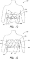
- Fig. 1C illustrates an electrode system 100 in accordance with a further embodiment of the present invention in which the plurality of ECG sensing electrodes 10 are again disposed at different axial positions around the body of a patient and generally located in a plane of the heart of the patient as in Fig. 1A .
- the plurality of ECG sensing electrodes 10 are integrated into a garment 20b, such as a belt, that is worn about the torso of the patient.
- ECG sensing electrodes 10 may include any type of ECG sensing electrodes, such as discrete, dry-sensing capacitive or conductive electrodes that are attached to the garment 20b by an adhesive or fastener, magnetically attached to the garment 20b, or sewn into the garment 20b.
- the plurality of ECG sensing electrodes 10 may be deployed about the patient's body in pairs of generally opposed electrodes (e.g., ECG sensing electrodes 10a, 10b), or may simply be axially spaced about the torso of the patient.
- Electrode system 100 of Fig. 1C also includes at least one driven ground electrode 12 that is attached to the garment 20b and may be used to reduce the effects of noise and/or detect if an ECG sensing electrode has fallen off.
- the at least one driven ground electrode 12 may be disposed in the same plane as the plurality of ECG sensing electrodes 10, or may be located in a different plane.
- the at least one driven ground electrode 12 may also be used as a therapy electrode to administer an electrical shock to the heart of the patient, as discussed further with respect to Fig. 1E below.
- the plurality of ECG sensing electrodes 10 may include ECG sensing electrodes positioned on side of the patient's torso, as well as the patient's front and back.
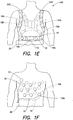
- Fig. 1D illustrates an electrode system 100 in accordance with yet another embodiment of the present invention in which the plurality of ECG sensing electrodes 10 are again integrated into a garment 20b, such as a belt that is worn over the torso of a patient, but in which the plurality of ECG sensing electrodes 10 are distributed more widely about the torso of the patient.
- the plurality of ECG sensing electrodes 10 are electrically coupled to a control unit 30 by a respective electrically insulated lead wire 15 (not all of which are shown for ease of illustration), and the electrode system 100 also includes at least one driven ground electrode 12.
- the at least one driven ground electrode 12 may include a first driven ground electrode that is generally disposed in a same plane as a plurality of the ECG sensing electrodes, and a second driven ground electrode disposed in a different plane.
- the plurality of ECG sensing electrodes 10 may be deployed in pairs (e.g., ECG electrodes 10a, 10b), or simply spaced apart about the torso of the patient.
- Fig. 1D is substantially similar to that of Figs. 1A-C , further discussion of those elements that are in common with Figs. 1A-C is omitted herein.
- Fig. 1E illustrates an electrode system 100 in accordance with an alternative embodiment of the present invention in which the plurality of ECG sensing electrodes 10 are again integrated into a garment 20c.
- the garment 20c is constructed in the form of a harness, such as that used in the Life Vest® Wearable Cardioverter Defibrillator.
- the harness includes an adjustable belt 110 and adjustable shoulder straps 120 that permit the harness be easily adjusted to fit different body types and sizes.
- the plurality of ECG sensing electrodes 10 are disposed about the body of the patient at varying locations along the belt 110 and shoulder straps 120 of the garment 20c.
- the plurality of ECG sensing electrodes 10 may be discrete, dry-sensing capacitive or conductive electrodes that are attached to the garment 20c, for example, by an adhesive, by hook and loop fasteners, or by sewing, or alternatively, the electrodes may be formed from electrically conductive threads sewn into the garment 20c.
- the plurality of ECG sensing electrodes 10 may be deployed in pairs of generally opposed electrodes (e.g., ECG sensing electrodes 10a and 10b), or alternatively, may not be deployed in pairs, but simply disposed at various locations about the body of the patient.
- the plurality of ECG sensing electrodes 10 will generally include ECG sensing electrodes disposed on the sides of the patient's body, as well as on the front and back of the patient's body.
- the electrode system 100 of Fig. 1E may include a control unit 30 that is electrically coupled to each of the plurality of ECG sensing electrodes 10 by a respective insulated lead wire 15, although wireless ECG sensing electrodes could alternatively be used.
- the control unit 30 may include a signal acquisition circuit, such as that described in more detail with respect to Figs. 2A-C , 3 , 9 , 10 , and 11 , and the control unit may also include a controller that may not only monitor the ECG signals from the patient, but may analyze those ECG signals and initiate electrical shock therapy to the patient in the event that such treatment is warranted.
- the control unit 30 may be integrated into the garment 20c, attached to the belt 110, received in a holster (not shown), or attached to a clip so that it may be easily worn by the patient, or the control unit 30 may be carried with the patient in any other convenient manner.
- the electrode system 100 also includes at least one driven ground electrode 12.
- the at least one driven ground electrode includes three driven ground electrodes 12a, 12b, and 12c.
- the driven ground electrodes 12a-c may be used in the manner described in the '669 patent to reduce the effects of noise and/or detect if an ECG sensing electrode has fallen off.
- the driven ground electrodes 12a-c can also be used as a therapy electrodes to deliver a defibrillating shock to the body of the patient, where such treatment is warranted.
- the electrodes 12a and 12b are electrically coupled together and act as a first therapy electrode, with electrode 12c acting as a second therapy electrode.
- the use of two therapy electrodes permits a biphasic shock to be delivered to the body of the patient, such that a first of the two therapy electrodes delivers a first phase of the biphasic shock with the other therapy electrode acting as a return, and the other therapy electrode delivers the second phase of the biphasic shock with the first therapy electrode acting as the return.
- a monophasic shock or other type of defibrillating pulse of energy may be used.
- Fig. 1F illustrates an electrode system 100 in accordance with another embodiment of the present invention that includes a plurality of ECG sensing electrodes 10.
- each of the plurality of ECG sensing electrodes 10 and the at least one driven ground electrode 12 is directly attached to the body of the patient.
- each of the plurality of ECG sensing electrodes 10 is electrically coupled to the control unit 30 by a respective insulating wire 15 (not all of which are shown for ease of illustration), and the electrode system 100 includes at least one driven ground electrode 12 that is electrically coupled to the control unit 30 by an insulated lead wire 18.
- the control unit 30 may include a signal acquisition circuit that is capable of selecting, from among the plurality of ECG sensing electrodes 10, those pairs of electrodes that provide the best ECG signals, in terms of signal level, noise, phase discrimination, or any other criteria.
- the plurality of ECG sensing electrodes 10 may be deployed about the body of the patient in pairs of generally opposed electrodes (e.g., ECG sensing electrodes 10a, 10b), or simply spaced about the torso of the patient.
- the plurality of ECG sensing electrodes 10 will typically include ECG sensing electrodes positioned on side of the patient's torso, as well as the patient's front and back. It should be appreciated that the embodiments of Figs. 1A-E may additionally include one or more ECG sensing electrodes (or driven ground electrodes) that are directly attached to the body of the patient, in addition to those that are integrated into the garment 20a- 20c.
- Fig. 1G illustrates a plan view of electrode system 100 of Figs. 1A-1E .
- the plurality of ECG sensing electrodes 10 are disposed at different axial positions about the body of the patient, although they need not be deployed in a single plane. Indeed, in at least one embodiment, the plurality of ECG sensing electrodes are not all co-located in a single plane so that pairs of electrodes corresponding to different planes may be selected.
- the plurality of ECG sensing electrodes 10 are shown as being deployed in generally diametrically opposed pairs of electrodes (e.g., electrodes 10a and 10b, electrodes 10c and 10d), it should be appreciated that the present invention is not so limited. In the embodiment depicted in Fig.
- the plurality of ECG sensing electrodes 10 includes 16 ECG sensing electrodes, with each ECG sensing electrode being spaced apart from an adjacent ECG sensing electrode by approximately 22.5°. In another embodiment, the plurality of ECG sensing electrodes 10 includes 12 sensing electrodes, with each ECG sensing electrode being spaced apart from an adjacent ECG electrode by approximately 30°, and in a further embodiment, the plurality of ECG sensing electrodes includes 18 sensing electrodes spaced approximately 20° apart. It should be appreciated that more or fewer ECG sensing electrodes may be provided, for example, as few as three, and that some or all of the ECG sensing electrodes may be located outside of a horizontal plane intersecting the heart of the patient.
- ECG sensing electrode 10a could be paired with either of ECG sensing electrodes 10k or 10j, rather than with ECG sensing electrode 10b, where such a pairing resulted in a better ECG signal level, better noise immunity, or a maximum phase discrimination, or where it was determined that ECG sensing electrode 10b had fallen off or has poor contact with the body of the patient.
- Different pairings of ECG sensing electrodes having a similar phase difference, or representing different phase differences may be selected and compared to one another.
- ECG sensing electrodes 10g and 10h that are spaced approximately 180° apart may be paired and the ECG signal compared to that from ECG sensing electrodes 10c and 10d (also spaced 180° apart), or alternatively, ECG sensing electrodes 10g and 10h may be paired and the ECG signal compared to that from ECG sensing electrodes 10b and 10d that are spaced approximately 90° apart in order to screen out noise or derive additional information.
- the pairings of ECG sensing electrodes may be selected to correspond to different planes. It should be appreciated that the different pairings of ECG sensing electrodes need not be disjoint.
- ECG sensing electrode 10a may be paired with ECG sensing electrode 10b and the ECG signal compared to that from ECG sensing electrodes 10a and 10c and/or to that from ECG sensing electrodes 10a and 10d.
- Fig. 2A illustrates a signal acquisition circuit that may be used with embodiments of the present invention to select, from among a plurality of ECG sensing electrodes, those pairings of electrodes that provide a desired ECG signal, in terms of signal-to-noise ratio, phase discrimination, or any other criteria, and provide those ECG signals to downstream circuitry for further signal conditioning, processing, analysis, and/or monitoring.
- the signal acquisition circuit 200 depicted in Fig. 2A may be used as a front end to the analog to digital conversion and signal conditioning block 14 described with respect to the arrhythmia detection system of Figs 2a-2c of the ' 669 patent.
- the signal acquisition circuit 200 includes a selection circuit 210 that is electrically coupled to a differential circuit 220. Signals from each of the plurality of ECG sensing electrodes 10a-10p are provided to a respective input 212 of the selection circuit 210. Signals from one or more of the driven ground electrodes 12 may also be provided to an input 212 of the selection circuit 210, such that a signal may be transmitted on the driven ground electrode 12, and that signal compared to the signals received on each of the plurality of ECG sensing electrodes to identify whether a particular ECG sensing electrode may have fallen off, or to identify noise issues relating to a particular ECG sensing electrode.
- the selection circuit 210 has a plurality of outputs 216 that are electrically coupled to respective inputs 222 of the differential circuit 220.
- the selection circuit 210 operates in a manner similar to a multiple output multiplexer, and includes a plurality of control inputs 214 to select signals from different ECG sensing electrodes and/or the driven ground electrode and provide those selected signals to the inputs 222 of the differential circuit 220. It should be appreciated that rather than a single selection circuit, a plurality of conventional single output multiplexers may be used to achieve the same functionality.
- the differential circuit 220 includes a plurality of analog differential instrumentation amplifiers 220a, 220b, ... 220n, to receive the signals provided by different pairings of the ECG sensing electrodes and/or different pairings of a respective ECG sensing electrode and a driven ground electrode and provide a respective differential output signal 226 corresponding to the difference therebetween.
- a differential ECG signal is provided.
- This differential analog ECG signal may then be digitally converted and conditioned by an analog-to-digital conversion and signal conditioning block of an arrhythmia detection system, such as that described with respect to Figs. 2a- 2c of the '669 patent, prior to further analysis and/or monitoring by an arrhythmia monitoring and/or treatment system, such as a wearable defibrillator.
- Fig. 2B illustrates an alternative signal acquisition circuit that may be used with embodiments of the present invention to select, from among a plurality of ECG sensing electrodes, those pairings of electrodes that provide a desired ECG signal, in terms of signal-to-noise ratio, phase discrimination, or any other criteria, and provide those ECG signals to downstream circuitry for further signal conditioning, processing, analysis, and/or monitoring.
- the signal acquisition circuit 200b is substantially similar to that of signal acquisition circuit 200a described immediately above with respect to Fig. 2A , and thus, only the selection circuit 210 is shown in Fig. 2B , and the other portions of circuit 200a, such as the differential circuit 220, are not depicted. However, in addition to being able to select any pairings of ECG sensing electrodes, the signal acquisition circuit 200b additionally allows any one of the plurality of ECG sensing electrodes 10a-10 ⁇ to be used as a driven ground electrode.
- a driven ground electrode is frequently used to eliminate noise that may be common to many or all sensors, such as ECG sensing electrodes 10a-10 ⁇ . Noise signals present on some or all of the sensors, such as the ECG sensing electrodes are summed, then inverted, and then injected into the driven ground circuitry. Where the sensors are ECG sensing electrodes that are attached to the body of a patient, the inverted signal may be actively driven onto the body of the patient where it is picked up by the ECG sensing electrodes, effectively cancelling out the noise that would normally be detected.
- the driven ground electrode 12 that is used to transmit the driven ground signal to the body of the patient may have fallen off, lost contact with the body of the patient, or simply not be working appropriately. Indeed, even where the driven ground electrode 12 is in good contact with the body of the patient and working properly, the driven ground electrode may simply be located in a sub-optimal position. Where any of these conditions exist, one or more of the plurality of ECG sensing electrodes 10a-10p may be used as a driven ground electrode. This aspect of the present invention in now described in more detail with respect to Fig. 2B .
- a plurality of signal pads 230 can be provided with each respective signal pad 230a-230p being electrically coupled to a driven ground circuit (not shown).
- a plurality of switches 232 are provided, with each respective switch 232a-p being electrically coupled between a respective ECG sensing electrode 10a-p and a respective input 212a-p of the selection circuit 210.
- Each switch 232a-p is capable of being in one of two positions. In a first position, the switch 232 electrically couples a respective ECG sensing electrode 10a-p to a respective input 212a-p of the selection circuit.
- the switch 232 electrically couples the respective electrode 10a-p to a respective signal pad 230a-p that is electrically coupled to the driven ground circuit.
- switch 232a is in a position such that the signal pad 230a is electrically coupled to ECG sensing electrode 10a
- each of switches 232b, 232c, ... 232p are in a position such that ECG sensing electrodes 10b-10 ⁇ are respectively electrically coupled to a respective input 212b-212p of the selection circuit 210.
- ECG sensing electrode 10a may be used as a driven ground electrode, where that use provides a better signal on others of the plurality of ECG sensing electrodes, where another driven ground electrode has lost contact or has poor contact with the body of the patient, or for any other reason.
- Fig. 2C illustrates a further alternative signal acquisition circuit that may be used with embodiments of the present invention to select pairings of ECG sensing electrodes in a manner similar to that described above with respect to Figs. 2A and 2B , and to allow any one of the plurality of ECG sensing electrodes to be used as a driven ground electrode in a manner similar to that described above with respect to Fig. 2B .
- the signal acquisition circuit 200c is substantially similar to that of signal acquisition circuit 200b described immediately above, and therefore, only the differences are described.
- each respective signal pad 230a-230p being electrically coupled to a driven ground circuit (not shown).
- a plurality of switches 232 are also provided. Each respective switch 232a-p of the plurality of switches 232 is electrically coupled to a respective signal pad 230a-p of the plurality of signal pad 230, which in turn, are electrically coupled to a driven ground circuit (not shown).
- Each switch 232a-p is capable of being in one of two positions, opened and closed.
- the driven ground signal on a respective signal pad 230a-p is an open circuit
- the switch 232 electrically couples a respective ECG sensing electrode 10a-p to a respective signal pad 230a-p.
- switch 232a and each of switches 232c-232p is in an open position
- switch 232b is in a closed position, such that the signal pad 230b is electrically coupled to ECG sensing electrode 10b.
- ECG sensing electrode 10b may be used as a driven ground electrode, where that use provides a better signal on others of the plurality of ECG sensing electrodes, where another driven ground electrode has lost contact or has poor contact with the body of the patient, or for any other reason.
- ECG sensing electrode 10a could be used as a driven ground electrode for use with ECG sensing electrodes 10c, 10d, 10o, 10 ⁇ , 10e, 10h, 10i, and 101 (see Fig. 1G ), and ECG sensing electrode 10b could be used as a driven ground electrode for use with ECG sensing electrodes 10m, 10p, 10g, 10f, 10k, and 10j.
- Fig. 3 illustrates a signal acquisition circuit according to another embodiment of the present invention that may be used to acquire signals from different pairings of ECG sensing electrodes, or from different pairings of ECG sensing electrodes and a driven ground electrode, and provide those signals to downstream circuitry, such as an A/D conversion and signal conditioning block 330 of an arrhythmia monitoring and/or treatment system.
- the signal acquisition circuit 300 includes a plurality of analog differential instrumentation amplifiers 320a-320n, 321a-321n-1, ... 329a that are each configured to receive signals from different pairings of ECG sensing electrodes.
- a first grouping of amplifiers 320a-320n may be configured to respectively pair each of ECG sensing electrodes 10b- 10p ( Fig. 1G ) with ECG sensing electrode 10a
- a second grouping of amplifiers 321a-321n-1 may be configured to respectively pair each of ECG sensing electrodes 10c-10p with ECG sensing electrode 10b
- each grouping of amplifiers may also compare a signal from a respective ECG sensing electrode with a driven ground electrode, or with each of a number of driven ground electrodes.
- individual signals from each of the different pairings of ECG sensing electrodes are provided directly to the inputs of a respective amplifier.
- this embodiment may avoid noise or signal degradation caused by the selection circuit 210 being located prior to the differential circuit 220.
- Such selection circuitry may instead be provided after an analog-to-digital conversion and signal conditioning block, such as the analog-to-digital conversion and signal conditioning block 14 described with respect to Figs 2a- 2c of the '669 patent.
- an analog-to-digital conversion and signal conditioning block such as the analog-to-digital conversion and signal conditioning block 14 described with respect to Figs 2a- 2c of the '669 patent.
- the analog differential output signals provided by each respective amplifier 320a-320n, 321a-321n-1, 329a may be provided to a respective input 332 of an A/D conversion and signal conditioning block 330 that digitizes and conditions the analog differential output signals.
- the digitized and conditioned signals provided on a respective output 334 of the A/D conversion and signal conditioning block 330 may then be provided to a respective input 342 of an output selection circuit 340 that operates in a manner similar to a multiple output multiplexer. Responsive to control signals provided to control inputs 344 of the selection circuit 340, the selection circuit selects, from among the plurality of digitized and conditioned signals, which of those digitized and conditioned signals to provide to a respective output 346 of the selection circuit for monitoring and/or analysis.
- each of the different pairings of ECG sensing electrodes 10 may be selected and their signals analyzed to identify those pairings of ECG sensing electrodes that provide a desired ECG signal, in terms of signal-to-noise ratio, phase discrimination, or any other criteria.
- Those pairings of ECG sensing electrodes providing the highest signal-to-noise ratio, a particular phase discrimination or a maximum phase discrimination, or those pairings of electrodes corresponding to particular planes may then be selected to provide those signals to a cardiac monitor, or to an arrhythmia detection system, such as that illustrated in Figs. 2a-c of the '669 patent.
- Figs. 2a-c arrhythmia detection system
- embodiments of the present invention provide a cardiac monitoring system and/or a cardiac monitoring and arrhythmia detection system with the ability to select, from among a plurality of electrodes, those pairings of electrodes that provide the highest quality signal, a particular phase difference or a maximum phase discrimination, or any other criteria.
- the analyzer of the cardiac monitoring and arrhythmia detection system can, for example, be tuned to give the best orthogonal view and can provide more cardiac information than a single or dual channel sensing system.
- the analyzer can select multiple templates representing different phase angles between ECG sensing electrode leads, or templates representing different planes of view of the patient's heart.
- Each electrode channel can be auto correlated (compared to itself) or cross correlated (compared with other channels) in order to screen out noise and derive additional information.
- Embodiments of the present invention can also return to the best axis positions if the overall electrode system was shifted at a later time, such as when the electrodes are configured as part of a wearable electrode belt or garment system. Because this multiple electrode configuration can select the electrodes with the best quality signal, the number of alarms due to ECG noise and fall-off can be reduced. Another byproduct of a cleaner ECG signal is a reduction in false detections. By checking multiple electrodes, and finding that the majority are sensing the same thing, embodiments of the present invention can increase the confidence level of the detection algorithm. In addition, each time the electrode belt or garment is worn, the electrodes may move to a slightly different location, resulting in a change to the ECG signal.
- the detection system can scan the multiple paths and select the highest quality signals. Furthermore, by providing redundancy to the sensing system, this multiple electrode configuration helps to improve the overall system reliability. A fault in one or more channels can be tolerated because there are other working channels.
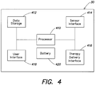
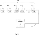
- Fig. 4 functionally illustrates a control unit, such as the control unit 30 depicted in Figs. 1A-F that may be used by a portable medical device, such as a cardiac monitor or a wearable defibrillator, in accordance with the present invention.
- the control unit 30 includes at least one processor 410, a battery 420, a data storage 412, a sensor interface 414, a therapy delivery interface 416, and a user interface 418.
- the battery 420 may be a rechargeable three cell 2200mAh lithium ion battery pack that provides electrical power to the other device components.
- the data storage 412, the sensor interface 414, the therapy delivery interface 416, and the user interface 418 are coupled to the at least one processor 410.
- the data storage 412 includes a computer readable and writeable data storage medium configured to store non-transitory instructions and other data, and can include both nonvolatile storage media, such as optical or magnetic disk, ROM or flash memory, as well as volatile memory, such as RAM.
- nonvolatile storage media such as optical or magnetic disk, ROM or flash memory
- volatile memory such as RAM
- the instructions may include executable programs or other code that can be executed by the at least one processor 410 to perform any of the functions described here below.
- the therapy delivery interface 416 couples one or more therapy delivery devices, such as defibrillator therapy electrodes 12a-c ( Fig. 1E ), to the at least one processor 410. Where the control unit is used solely for monitoring a patient's cardiac condition, the therapy interface 416 and associated defibrillation therapy electrodes may be omitted.
- the user interface 418 includes a combination of hardware and software components that allow the control unit 30 to communicate with an external entity, such as a user. These components are configured to receive information from actions such as physical movement, verbal intonation or thought processes. In addition, the components of the user interface 418 can provide information to external entities, for example, in a manner such as described in U.S. Patent No. 6,681,003 . Examples of the components that may be employed within the user interface 418 include keyboards, mouse devices, trackballs, microphones, electrodes, touch screens, printing devices, display screens and speakers.
- the sensor interface 414 couples the at least one processor 410 to a plurality of physiological sensors, such as the plurality of ECG sensing electrodes 10. In some embodiments, the sensor interface 414 may also couple the at least one processor 410 to other physiological sensors, such as activity sensors, pulse oxygen sensors, temperature sensors, respiratory rate sensors, thoracic impedance sensors, blood pressure sensors, acoustic sensors, etc.
- the sensor interface 414 can include a signal acquisition circuit, such as the signal acquisitions circuits 200 and 300 described above with respect to Figs. 2A-C and 3 , or the signal acquisition circuits 900, 1000, and 1100 described further below with respect to Figs. 9-11 , to select, from among the plurality of ECG sensing electrodes and/or other physiological sensors, those that provide a desired signal, in terms signal-to-noise ratio, phase discrimination, or any other criteria.
- control unit 30 may include additional components and or interfaces, such as a communication network interface (wired and/or wireless), and the at least one processor 410 may include a power conserving processor arrangement such as described in US 2012/0011382 A1 .
- the at least one processor 410 may include a general purpose processor, such as an Intel® PXA270 processor that is coupled to a critical purpose processor, such as a FreescaleTM DSP56311 Digital Signal Processor (DSP).
- DSP Digital Signal Processor
- the general purpose processor can be configured to perform noncritical functions that do not require real time processing, such as interfacing with the communication network interface and the user interface, while the critical purpose processor is configured to perform critical functions that require real time processing, such as the sampling and analysis of ECG information, the charging of the capacitors to a particular voltage, and the generation and/or delivery of therapeutic defibrillating pulses.
- the functionality of the at least one processor may be implemented in a Field Programmable Gate Array (FPGA), one or more Programmable Logic Devices (PLDs), a Complex PLD (CPLD), or custom Application Specific Integrated Circuit (ASIC).
- FPGA Field Programmable Gate Array
- PLDs Programmable Logic Devices
- CPLD Complex PLD
- ASIC Application Specific Integrated Circuit
- Figures 5-8 illustrate a number of different processes that may be performed by the at least one processor 410 of the control unit 30 to improve the monitoring and analysis of cardiac activity, to improve the detection of cardiac abnormalities, and to reduce the number of false detections and fall-off alarms in accordance with embodiments of the present invention.
- Fig. 5 illustrates a selection process that may be executed by the at least one processor 410 of the control unit 30 to select, from among a plurality of ECG sensing electrodes 10, those providing a highest quality ECG signal, in terms of signal-to-noise ratio and maximum phase discrimination, in accordance with one embodiment of the present invention.
- the at least one processor 410 selects a pair of ECG sensing electrodes to monitor. As discussed previously, this may be performed by the at least one processor sending appropriate control signals to selection circuit 210, 340.
- the at least one processor analyzes the ECG signal obtained from the selected pair of ECG sensing electrodes and records information identifying the selected pair of ECG sensing electrodes and a metric indicative of the quality of the ECG signal provided therefrom. Although a number of different criteria may be used to identify the quality of the ECG signal, in one embodiment, those ECG signals having a highest signal-to-noise ratio and a maximum phase discrimination are assigned a higher quality metric than those pairings that do not.
- the at least one processor determines whether each of the possible pairings of ECG sensing electrodes have been selected and analyzed. Where it is determined that all the possible pairings of ECG sensing electrodes have been selected and analyzed, the process proceeds to act 540. Alternatively, where it is determined that fewer than all of the possible pairs of ECG sensing electrodes have been selected and analyzed, the process returns to act 510, where a next sensor pairing is selected. Acts 510 through 530 are then performed for each of the possible pairings of ECG sensing electrodes.
- the at least one processor selects, from among the plurality of different pairings of ECG sensing electrodes, those pairs of ECG sensing electrodes having the highest quality metric. It should be appreciated that the number of different pairings of ECG sensing electrodes that are selected in act 540 will depend on the number of different channels provided at the output 226 of the differential circuit 220 ( Fig. 2A ) or at the output 346 of the selection circuit 340 of Fig. 3 . In general, a minimum of two channels would be selected in act 540, and in most implementations, at least four different channels would be selected. In some embodiments, the number of channels provided may correspond to each unique pairing of electrodes.
- the at least one processor monitors and analyzes the ECG signals provided by the selected pairings of ECG sensing electrodes.
- the act of monitoring and analyzing the ECG signals provided by the selected ECG sensor pairs may continue until the terminated by removal and/or power down of the wearable medical device.
- the selection process described with respect to Fig. 5 may be performed each time the electrode system 100 is powered on to account for any potential repositioning of the plurality of electrodes 10 on the body of the patient.
- the positioning of some or all of the ECG sensing electrodes may change from their prior position.
- the electrode system may select those pairings of ECG sensing electrodes that provide the highest quality ECG signals, irrespective of whether those pairings of ECG electrodes are the same, or different from those selected previously.
- an initial pairing of ECG sensing electrodes may be based upon those that were previously selected in act 540. For example, in response to a garment incorporating an electrode system 100 being removed from and returned to the body of a patient, the electrode system may initially select pairings of ECG sensing electrodes based upon those that were selected prior to removal of the garment in act 540. That initial selection may then be confirmed by re-executing the selection process of Fig. 5 .
- the selection process described with respect to Fig. 5 may be re-executed, either at periodic intervals (e.g., every half hour), or in response to another sensor, such as an activity sensor, indicating strenuous physical activity, to ensure the optimal pairings of ECG sensing electrodes are selected.
- another sensor such as an activity sensor, indicating strenuous physical activity
- embodiments of the present invention can ensure that those pairings of ECG sensing electrodes providing the highest quality ECG are identified and used for monitoring and analysis.
- Fig. 5 Although the selection process of Fig. 5 was described as selecting those pairs of ECG sensing electrodes providing the highest quality ECG signal, in terms of signal-to-noise ratio and maximum phase discrimination, it should be appreciated that other criteria may be used.
- the process described with respect to Fig. 5 may be modified to include an act of selecting a desired template prior to act 510.
- the desired template may, for example, reflect different phase angles between ECG sensing electrodes that are desired to be monitored.
- the acts 510 and 520 of selecting and analyzing different ECG sensing electrode pairings could thus select, from among the plurality of ECG sensing electrodes, those pairs of ECG sensing electrodes that provide the highest signal-to-noise ratio from among those pairings that meet the desired phase angle(s) of the template.
- one template may correspond to different pairings of ECG sensing electrodes that correspond to different planes intersecting the patient's heart, while another template may correspond to different pairing of ECG sensing electrodes that are all co-located in the same plane.
- Fig. 6 illustrates a noise/fall-off detection process that may be executed by the at least one processor 410 of the control unit 30 ( Fig. 4 ) in accordance with an aspect of the present invention to improve the quality of monitoring and analysis of ECG signals and/or to reduce the number of fall-off alarms.
- the at least one processor monitors and analyzes selected ECG signals from different pairings of ECG sensing electrodes.
- the pairings of ECG sensing electrodes that are monitored and analyzed in act 610 may have been previously selected based upon a selection process such as that described with respect to Fig. 5 .
- the at least one processor makes a determination as to whether there is noise in the ECG signal of a selected pairing of ECG sensing electrodes, or whether there has been a fall-off or at least partial loss of contact with the body of the patient by a selected pairing of ECG sensing electrodes. Where it is determined in act 620 that there is no appreciable noise or a diminished signal or a lack of signal on any of the selected pairings of ECG sensing electrodes, the at least one processor returns to act 610 and continues monitoring the selected ECG signals.
- the process proceeds to act 630.
- act 630 the at least one processor 410 selects a new pairing of ECG sensing electrodes to replace the pairing in which increased noise, or a diminished ECG signal was detected.
- Act 630 may be performed in a manner similar to the selection process described with respect to Fig. 5 .
- each of the possible pairings of ECG sensing electrodes may be re-evaluated to select those pairings of ECG electrodes to be monitored.
- those selected pairings of ECG sensing electrodes in which noise or fall-off was not detected may be retained as selected pairings, and the remaining ECG sensing electrodes evaluated to identify and select a pairing of ECG sensing electrodes to replace the pairing in which noise or fall-off was detected.
- the process returns to monitoring an analyzing ECG signals in act 610.
- the at least one processor 410 may conduct additional tests on the selected pairing. For example, the at least one processor may pair each ECG sensing electrode of the selected pair with a driven ground electrode to identify which of the ECG sensing electrodes of the selected pair may have a noise issue or may have at least partially lost contact with the body of the patient.
- the at least one processor 410 may also send a message to the user of portable medical device (or a bystander) via the user interface 418 to notify the user that one or more of the ECG sensing electrodes of the selected pairing may have a noise issue or may have at least partially lost contact with the body of the patient, and may further request the user to reposition the ECG sensing electrodes of the selected pairing.
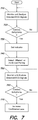
- Fig. 7 illustrates monitoring and analysis routine that may be executed by the at least one processor 410 of the control unit 30 to improve the detection of cardiac arrhythmias and reduce the number of false detections.
- the at least one processor monitors and analyzes selected ECG signals from different pairings of ECG sensing electrodes.
- the pairings of ECG sensing electrodes that are monitored and analyzed in act 710 may have been previously selected based upon a selection process such as that described with respect to Fig. 5 .
- act 720 a determination is made as to whether a cardiac arrhythmia has been detected.
- the process returns to act 710 and continues to monitor and analyze the selected ECG signals.
- the at least one processor proceeds to act 730 wherein the at least one processor sets a flag or indicator identifying that a cardiac arrhythmia has been detected, with the at least one processor proceeding to act 740.
- the at least one processor 410 selects a different or additional pairing of ECG sensing electrodes to monitor, to identify whether the determined arrhythmia is also present in the ECG signals from other pairings of ECG sensing electrodes.
- the additional or different pairings of ECG sensing electrodes may be based upon the selection process described previously with respect to Fig. 5 .
- the additional or different pairings of ECG sensing electrodes that are selected in act 740 may be one or more of those pairings that provides the next highest signal quality level other than those that were selected in act 540 of Fig. 5 .
- the at least one processor continues to monitor and analyze the selected ECG signals, including those from additional or different pairings of ECG sensing electrodes selected in act 740.
- the at least one processor 410 again determines whether a cardiac arrhythmia has been detected, based upon the ECG signals monitored in act 750. Where it is determined that a cardiac arrhythmia has not been detected in the different or additional pairings, the at least one processor may simply return to act 750 and continue to monitor the selected ECG signals. However, where it is determined in act 760 that a cardiac arrhythmia, such as ventricular tachycardia or ventricular fibrillation has been detected, the at least one processor may proceed to act 770.
- the at least one processor increases a confidence level of the indicator or flag set in act 730.
- the at least one processor 410 may execute one or more instructions that result in defibrillation being applied to the body of the patient via the therapy delivery interface 416.
- the detection specificity of cardiac arrhythmias may be increased and the number of false detections of cardiac malfunction may be reduced.
- Fig. 8 illustrates a monitoring and analysis routine in accordance with another embodiment of the present invention that may be executed by the at least one processor 410 of the control unit 30 to improve the monitoring and analysis of cardiac activity.
- the at least one processor monitors and analyzes selected ECG signals from different pairings of ECG sensing electrodes.
- the pairings of ECG sensing electrodes that are monitored and analyzed in act 810 may have been previously selected based upon a selection process such as that described with respect to Fig. 5 , or they may have been selected for other reasons.
- the pairings of ECG electrodes may not provide the highest quality ECG signal of all of the ECG sensor pairs, but may correspond to a particular plane or planes, or to a particular position relative to the heart.
- the at least one processor 410 monitors and analyzes the ECG signals provided by the selected pairings of ECG sensing electrodes.
- a determination is made as to whether to select new pairs of ECG sensing electrodes to monitor. The determination as to whether to select new pairs of ECG sensing electrodes may be based upon a number of different criteria, including the number of channels that are capable of being monitored and analyzed at a time, the type of information that is sought, the stage of the cardiac cycle (e.g., the diastolic stage, or the systolic stage), the position of the ECG sensing electrodes relative to the heart and/or the stage of depolarization or repolarization of the heart (e.g., as indicated by PQRST waveform of the ECG signals), etc.
- control unit 30 is capable of simultaneously monitoring three different channels and the plurality of ECG sensing electrodes 10 includes 12 ECG sensing electrodes
- three pairings of ECG sensing electrodes may be monitored and analyzed during a first time interval, and the remaining three pairings of ECG sensing electrodes that were not monitored and analyzed during the first interval may be monitored and analyzed during a second and subsequent time interval.
- control unit is capable of simultaneously monitoring three different channels and the plurality of ECG sensing electrodes 10 includes 16 ECG sensing electrodes (as shown in Fig.
- three different pairings of ECG sensing electrodes including ECG sensing electrode pairs 10o-10 ⁇ , 10c-10d, 10m- 1 On may be monitored and analyzed during a first time interval
- three different pairings of ECG sensing electrodes including ECG sensing electrode pairs 10g-10h, 10k-101, and 10b-10a may be monitored during a second interval
- three different pairs of ECG sensing electrodes including ECG sensing electrodes pairs 10j-10i, 10f-10e, and 10o-10p may be monitored and analyzed during a third time interval.
- the selected pairings of ECG electrodes may sweep about the circumference of the heart. It should be appreciated that where the number of channels that can be simultaneously monitored by the control unit 30 are sufficient to monitor all pairings of ECG sensing electrodes, or all unique pairings of ECG sensing electrodes, then all such pairings may be monitored simultaneously.
- act 830 where it is determined that a new or different pairing of ECG sensing electrodes are to be monitored and analyzed, the monitoring and analysis routine returns to act 810 wherein those new or different pairings of ECG sensing electrodes are selected (act 810) and monitored and analyzed (act 820).
- act 810 where it is determined in act 830 that a new or different pairing of ECG sensing electrodes is not desired, the routine returns to act 820 and continues monitoring the pairings of previously selected ECG sensing electrodes.
- Fig. 9 illustrates an alternative signal acquisition circuit that may be used with embodiments of the present invention to select, from among a plurality of ECG sensing electrodes, those pairing of electrodes that provide a desired ECG signal, in terms of signal-to-noise ratio, phase discrimination, or any other criteria, and provide those ECG signals to downstream circuitry for further signal conditioning, processing, analysis, and/or monitoring.
- the signal acquisition circuit 900 does not include any differential amplifiers but instead generates differential ECG signals corresponding to selected pairings of ECG sensing electrodes in software executed by a processor, such as the at least one processor 410 described previously with respect to Fig. 4 .
- the signal acquisition circuit 900 includes an analog multiplexor 910 and an analog-to-digital (A/D) converter 920. Signals from each of the plurality of ECG sensing electrodes 10a-10p are provided to a respective input of a plurality of inputs 912 of the analog multiplexor 910.
- the analog multiplexor has an output 916 that is electrically coupled to an input 922 of the A/D converter 920.
- the analog multiplexor 910 includes a plurality of control inputs 914 to select which one of the plurality of signals received from a respective ECG sensing electrode 10a- 10p is provided to the input 922 of the of the A/D converter 920.
- the A/D converter 920 receives the selected signal from the selected one of the plurality of ECG sensing electrodes and converts that analog ECG sensor signal to a digital signal.
- the A/D converter 920 may be a 24 bit A/D converter, although an A/D converter with fewer bits may be used.
- the sampling rate of the A/D converter 920 should be at least N times the desired sampling rate of the ECG signal, where N is the number of ECG sensing electrodes that are desired to be monitored.
- the A/D converter 920 should have a sampling rate in excess of 2.4 KHz. It should be appreciated that higher sampling rates may of course be used.
- each of the signals from a respective ECG sensing electrode 10-10p may first be buffered, filtered, and/or amplified prior to being received at a respective input of the analog multiplexor 910.
- each of the signals received from a respective one of the plurality of ECG sensing electrodes 10a-p may be provided to the input of a high impedance buffer so that the analog multiplexor and the A/D converter to do not load down the respective ECG sensing electrode.
- the output of a respective buffer may be low-pass filtered (i.e., anti-aliased) to ensure that any frequency components of the signal are below the Nyquist frequency of the A/D converter 920, and the filtered signal provided to a low-noise and low to moderate gain amplifier to amplify the signal before that signal is provided to a respective input of the analog multiplexor 910.
- the combination of buffering, filtering, and/or amplifying the signal received from each of the plurality of ECG sensing electrodes may be performed in multiple and distinct stages (e.g., a high impedance buffer stage followed by a filtering stage and one or more amplification stages), or some of the stages, such as the buffering and amplification stages may be performed in a single stage (e.g., a high impedance low-noise amplifier with low to moderate gain).
- the amplification stage may be programmable by the at least one processor 410.
- the analog multiplexer 910 may be a conventional analog multiplexer, available from companies such as Analog Devices, Inc. of Norwood Massachusetts, in which control signals received on the control inputs of the analog multiplexer select which one of the signals received on a respective input of the multiplexer is provided to the output.
- the A/D converter 910 converts the received signal to a digital signal and provides the converted digital signal to the at least one processor 410.
- the at least one processor is configured to control the multiplexor 910 and the A/D converter 920 to sample and convert each of the signals received from a respective ECG sensing electrode over a different time interval and provide the converted signals to the at least one processor 410.
- the at least one processor 410 takes the two selected digital signals, inverts one of them, and digitally sums the signals, effectively performing the same functionality as the differential instrumentation amplifiers described with respect to Figs. 2A-C and 3 above.
- the selection, inversion, and summing of selected pairs of digital signals may be performed for any pairing of ECG sensing electrodes.
- the digitally summed signals may then be processed to monitor the patient's ECG signals, to detect any arrhythmic cardiac condition, or both. It should be appreciated that which of the pairs of ECG sensing electrodes to pair and monitor may be performed in software by the at least one processor in a manner similar to that shown in Fig.
- Each of the digitized signals may be compared to one another for maximum phase difference, or a specific phase difference, or for any other criterion. Those pairings of ECG sensing electrodes may then be selected and monitored and analyzed in the manner described above.
- the analog multiplexer 910 may be an analog sample-and-hold multiplexer that is capable of simultaneously sampling signals received from each of the plurality of ECG sensing electrodes over a first time period, and then providing each of the plurality of sampled signals to the A/D converter 920 during subsequent time periods.
- the at least one processor 410 is configured to control the analog multiplexer 910 and the A/D converter 920 to sample and hold the signals received from each of the plurality of ECG sensing electrodes 10a-p over a first time period, and provide each, or selected ones, of the sampled signals to the A/D converter 920 to be converted to digital signals and provided to the at least one processor over subsequent time periods.
- the at least one processor 410 takes the two selected digital signals, inverts one of them, and digitally sums the signals, effectively performing the same functionality as the differential instrumentation amplifiers described with respect to Figs. 2A-C and 3 above.
- the selection, inversion, and summing of selected pairs of digital signals may be performed for any pairing of ECG sensing electrodes.
- the digitally summed signals may then be processed to monitor the patient's ECG signals and/or to detect any arrhythmic cardiac condition.
- Fig. 10 illustrates a further alternative signal acquisition circuit that may be used with embodiments of the present invention to select, from among a plurality of ECG sensing electrodes, those pairing of electrodes that provide a desired ECG signal, in terms of signal-to-noise ratio, phase discrimination, or any other criteria, and provide those ECG signals to downstream circuitry for further signal conditioning, processing, analysis, and/or monitoring.
- the signal acquisition circuit 1000 does not include any differential amplifiers, but instead generates differential ECG signals corresponding to selected pairings of ECG sensing electrodes in software executed by a processor, such as the at least one processor 410 described previously with respect to Fig. 4 .
- the signal acquisition circuit 1000 includes a plurality of analog-to-digital (A/D) converters 1010a-p.
- Each of the plurality of A/D converters 1010a-p is configured to receive a signal from a respective one of the plurality of ECG sensing electrodes 10a-p, for example, with a first A/D converter 1010a receiving a signal from ECG sensing electrode 10a, A/D converter 1010b receiving a signal from ECG sensing electrode 10b, etc.
- Each respective A/D converter 1010a-p converts the signal to a digital signal and provides the converted digital signal to the at least one processor 410 over a communication link 1020, such as a serial or parallel bus.
- each of the signals from a respective ECG sensing electrode 10-10p may first be buffered, filtered, and/or amplified prior to being received at a respective input of a respective A/D converter 1010a-p in a manner similar to that described above with respect to Fig. 9 so that the A/D converter does not load down the respective ECG sensing electrode, and to ensure that any frequency components of the received signals are below the Nyquist frequency of a respective A/D converter 1010a-p.
- each of the plurality of A/D converters 1010a-p may be a 24 bit A/D converter, although an A/D converter with fewer bits may be used.
- each of plurality of A/D converters 1010a-p of this embodiment need not have a sampling rate that is N times the desired sampling rate of the ECG signal, where N is the number of ECG sensing electrodes that are desired to be monitored, because each of the signals received from a respective ECG sensing electrode may be sampled in parallel.
- each of the plurality of A/D converters may have a sampling rate of 400Hz, thereby allowing the use of less costly A/D converters.
- the at least one processor 410 may send a control signal to each of the plurality of A/D converters 1010a-p to sample a respective signal at substantially the same period of time, and then send the sampled and converted digital signal to the processor at a subsequent time.
- the at least one processor takes the two selected digital signals, inverts one of them, and digitally sums the signals, effectively performing the same functionality as the differential instrumentation amplifiers described with respect to Figs. 2A-C and 3 above.
- the selection, inversion, and summing of selected pairs of digital signals may again be performed for any pairing of ECG sensing electrodes.
- the digitally summed signals may then be processed to monitor the patient's ECG signals and/or to detect any arrhythmic cardiac condition.
- Fig. 11 illustrates yet a further alternative signal acquisition circuit that may be used with embodiments of the present invention to select, from among a plurality of ECG sensing electrodes, those pairing of electrodes that provide a desired ECG signal, in terms of signal-to-noise ratio, phase discrimination, or any other criteria, and provide those ECG signals to downstream circuitry for further signal conditioning, processing, analysis, and/or monitoring.
- This embodiment is similar to the embodiment described above with respect to Figs. 9 and 10 in that it again does not include any differential amplifiers, but instead generates differential ECG signals corresponding to selected pairings of ECG sensing electrodes in software executed by a processor, such as the at least one processor 410 described previously with respect to Fig. 4 .
- the signal acquisition circuit 1100 shown in Fig. 11 again includes a plurality of analog-to-digital (A/D) converters 11 10a-p, each of which is configured to receive a signal from a respective one of the plurality of ECG sensing electrodes 10a-p.
- A/D analog-to-digital
- each of the signals from a respective ECG sensing electrode 10-1 Op may first be buffered, filtered, and/or amplified prior to being received at a respective input of a respective A/D converter 11 10a-p in a manner similar to that described above with respect to Figs. 9 and 10 so that the A/D converter does not load down the respective ECG sensing electrode, and to ensure that any frequency components of the received signal are below the Nyquist frequency of a respective A/D converter 1110a-p.
- each of the plurality of A/D converters 1110a-p of this embodiment are daisy chained (or cascaded) to one another, for example via a serial bus, such as a SPITM serial bus, a QSPITM serial bus, or MicrowireTM serial bus.
- a serial bus such as a SPITM serial bus, a QSPITM serial bus, or MicrowireTM serial bus.
- Each respective A/D converter 11 10a-p is arranged to sample a signal from a respective one of the plurality of ECG sensing electrodes 10a-p during a first time interval, and convert the signal to a digital signal and provide the converted digital signal to the next A/D converter in the chain during a subsequent time interval.
- the output of the last A/D converter 11 10p in the chain is communicatively coupled to the at least one processor via a communication link 1120, such as a serial bus.
- the output of the last A/D converter in the chain (e.g., A/D converter 11 10p) therefore provides a multi-bit signal to the at least one processor 410 with different bits in the multi-bit signal corresponding to different ECG sensing electrodes, for example, with a first series of bits corresponding to the converted digital signal obtained from ECG sensing electrode 10p, the second series of bits corresponding to the converted digital signal obtained from ECG sensing electrode 10o, and the last series of bits corresponding to the converted digital signal obtained from ECG sensing electrode 10a.
- each of the plurality of A/D converters 1110a-p may be a 24 bit A/D converter, although an A/D converter with fewer bits, such as 16 bits may alternatively be used.
- each of plurality of A/D converters 11 10a-p of this embodiment need not have a sampling rate that is N times the desired sampling rate of the ECG signal, where N is the number of ECG sensing electrodes that are desired to be monitored, because each of the signals received from a respective ECG sensing electrode may be sampled in parallel.
- each of the plurality of A/D converters may operate at that same sampling rate, thereby allowing the use of less costly A/D converters.
- the rate at which the converted digital signals are communicated from one A/D converter to the next, and then to the at least one processor 410 should be at least N times the desired sampling rate of the ECG signal, where N corresponds to the number of ECG sensing electrodes that are desired to be monitored.
- a suitable type of A/D converter that can be cascaded or daisy chained in the manner described above is a MAX 11040K (24 bit) or Maxl I060 (16 bit) ADC available from Maxim Integrated Products of Sunnyvale California, although other analog-to digital converters available from other companies may alternatively be used.
- the at least one processor 410 may send a control signal to each of the plurality of A/D converters 1110a-p to sample a respective signal at substantially the same period of time, and send the sampled and converted digital signal to the next A/D converter in the chain, at a subsequent time.
- the last A/D converter 11 10 ⁇ provides the serial bitstream to the at least one processor 410.
- the at least one processor 410 extracts the digital signals corresponding to the two selected digital signals (typically corresponding to the same time period), inverts one of them, and digitally sums the signals, effectively performing the same functionality as the differential instrumentation amplifiers described with respect to Figs. 2A-C and 3 above.
- the selection, inversion, and summing of selected pairs of digital signals may be performed for any pairing of ECG sensing electrodes, and corresponding to the same, or different time periods.
- the digitally summed signals may then be processed to monitor the patient's ECG signals and/or to detect any arrhythmic cardiac condition.
- each of these signal acquisition circuits not only permit the monitoring and analysis of ECG signals from any pairing of ECG sensing electrodes that are associated with the wearable ambulatory medical device, but they also permit the signal of any of the plurality of ECG sensing electrodes 10a-p to be paired with the signal from another source, such as a wireless ECG sensing electrode.
- a wireless ECG sensing electrode may be provided that includes an A/D converter, such as any of A/D converters 1010a-p or 1110a-p described above, that is coupled to a wireless transmitter or transceiver and can communicate with the at least one processor 410 via a wireless communication protocol such as Bluetooth, ZigBee, Wireless USB, Wireless Ethernet, GSM, etc.
- the signal from the wireless ECG sensing electrode may then be paired with any of the signals from each of ECG sensing electrodes 10-p that are associated with the wearable ambulatory medical device, where it is desirable to do so. In this manner, if additional cardiac information is desired, additional wireless ECG sensing electrodes may be placed on the patient's body, and those signals monitored and analyzed.
- each of the ECG sensing electrodes need not be associated with a garment that is worn by the patient, but each of the ECG sensing electrodes may be self adhesive wireless ECG sensing electrodes that are simply placed, as desired, on the patient's body.
Landscapes
- Health & Medical Sciences (AREA)
- Life Sciences & Earth Sciences (AREA)
- Engineering & Computer Science (AREA)
- Animal Behavior & Ethology (AREA)
- Veterinary Medicine (AREA)
- Public Health (AREA)
- General Health & Medical Sciences (AREA)
- Biomedical Technology (AREA)
- Physics & Mathematics (AREA)
- Heart & Thoracic Surgery (AREA)
- Molecular Biology (AREA)
- Surgery (AREA)
- Medical Informatics (AREA)
- Pathology (AREA)
- Biophysics (AREA)
- Cardiology (AREA)
- Physiology (AREA)
- Signal Processing (AREA)
- Nuclear Medicine, Radiotherapy & Molecular Imaging (AREA)
- Radiology & Medical Imaging (AREA)
- Computer Vision & Pattern Recognition (AREA)
- Artificial Intelligence (AREA)
- Psychiatry (AREA)
- Pulmonology (AREA)
- Dentistry (AREA)
- Oral & Maxillofacial Surgery (AREA)
- Computer Networks & Wireless Communication (AREA)
- Vascular Medicine (AREA)
- Optics & Photonics (AREA)
- Measurement And Recording Of Electrical Phenomena And Electrical Characteristics Of The Living Body (AREA)
- Electrotherapy Devices (AREA)
- Chemical & Material Sciences (AREA)
- Dispersion Chemistry (AREA)
Applications Claiming Priority (3)
| Application Number | Priority Date | Filing Date | Title |
|---|---|---|---|
| US34591410P | 2010-05-18 | 2010-05-18 | |
| US201061424344P | 2010-12-17 | 2010-12-17 | |
| PCT/US2011/036805 WO2011146482A1 (en) | 2010-05-18 | 2011-05-17 | Wearable ambulatory medical device with multiple sensing electrodes |
Publications (3)
| Publication Number | Publication Date |
|---|---|
| EP2571419A1 EP2571419A1 (en) | 2013-03-27 |
| EP2571419A4 EP2571419A4 (en) | 2014-11-26 |
| EP2571419B1 true EP2571419B1 (en) | 2020-02-12 |
Family
ID=44973110
Family Applications (1)
| Application Number | Title | Priority Date | Filing Date |
|---|---|---|---|
| EP11784088.4A Active EP2571419B1 (en) | 2010-05-18 | 2011-05-17 | Wearable ambulatory medical device with multiple sensing electrodes |
Country Status (6)
| Country | Link |
|---|---|
| US (9) | US8706215B2 (enExample) |
| EP (1) | EP2571419B1 (enExample) |
| JP (2) | JP5922103B2 (enExample) |
| CN (2) | CN105054924A (enExample) |
| BR (1) | BR112012029240A2 (enExample) |
| WO (1) | WO2011146482A1 (enExample) |
Cited By (1)
| Publication number | Priority date | Publication date | Assignee | Title |
|---|---|---|---|---|
| EP4520261A4 (en) * | 2023-07-14 | 2025-03-12 | Shenzhen Shokz Co., Ltd. | ELECTROCARDIOGRAM MONITORING SYSTEM AND METHOD |
Families Citing this family (358)
| Publication number | Priority date | Publication date | Assignee | Title |
|---|---|---|---|---|
| US7330757B2 (en) | 2001-11-21 | 2008-02-12 | Cameron Health, Inc. | Method for discriminating between ventricular and supraventricular arrhythmias |
| US20040116969A1 (en) | 2002-08-26 | 2004-06-17 | Owen James M. | Pulse detection using patient physiological signals |
| US8369944B2 (en) | 2007-06-06 | 2013-02-05 | Zoll Medical Corporation | Wearable defibrillator with audio input/output |
| US8271082B2 (en) | 2007-06-07 | 2012-09-18 | Zoll Medical Corporation | Medical device configured to test for user responsiveness |
| US8140154B2 (en) | 2007-06-13 | 2012-03-20 | Zoll Medical Corporation | Wearable medical treatment device |
| US7974689B2 (en) | 2007-06-13 | 2011-07-05 | Zoll Medical Corporation | Wearable medical treatment device with motion/position detection |
| JP5986991B2 (ja) | 2010-05-18 | 2016-09-06 | ゾール メディカル コーポレイションZOLL Medical Corporation | 着用可能な治療装置 |
| WO2011146482A1 (en) | 2010-05-18 | 2011-11-24 | Zoll Medical Corporation | Wearable ambulatory medical device with multiple sensing electrodes |
| US10493289B2 (en) | 2010-07-09 | 2019-12-03 | Zoll Medical Corporation | System and method for conserving power in a medical device |
| US9937355B2 (en) | 2010-11-08 | 2018-04-10 | Zoll Medical Corporation | Remote medical device alarm |
| WO2012078857A2 (en) | 2010-12-09 | 2012-06-14 | Zoll Medical Corporation | Electrode with redundant impedance reduction |
| BR112013014219A2 (pt) | 2010-12-10 | 2016-09-13 | Zoll Medical Corp | dispositivo terapêutico de vestir |
| US9427564B2 (en) | 2010-12-16 | 2016-08-30 | Zoll Medical Corporation | Water resistant wearable medical device |
| US9237858B2 (en) | 2011-02-09 | 2016-01-19 | West Affum Holdings Corp. | Detecting loss of full skin contact in patient electrodes |
| US9317729B2 (en) | 2011-02-09 | 2016-04-19 | West Affum Holdings Corp. | RFID-based sensing of changed condition |
| EP2689363B1 (en) | 2011-03-25 | 2022-07-27 | Zoll Medical Corporation | System and method for adapting alarms in a wearable medical device |
| US9684767B2 (en) | 2011-03-25 | 2017-06-20 | Zoll Medical Corporation | System and method for adapting alarms in a wearable medical device |
| WO2012135062A1 (en) * | 2011-03-25 | 2012-10-04 | Zoll Medical Corporation | Selection of optimal channel for rate determination |
| US8600486B2 (en) | 2011-03-25 | 2013-12-03 | Zoll Medical Corporation | Method of detecting signal clipping in a wearable ambulatory medical device |
| CN103797681B (zh) * | 2011-04-28 | 2018-05-11 | 佐尔循环公司 | 跟踪并存档电池性能数据的系统和方法 |
| JP2014516654A (ja) | 2011-05-02 | 2014-07-17 | ゾール メディカル コーポレイション | 患者着用式エネルギ供給装置およびそのサイズを調節する技術 |
| US9069380B2 (en) | 2011-06-10 | 2015-06-30 | Aliphcom | Media device, application, and content management using sensory input |
| US20130198694A1 (en) * | 2011-06-10 | 2013-08-01 | Aliphcom | Determinative processes for wearable devices |
| JP2014526282A (ja) | 2011-09-01 | 2014-10-06 | ゾール メディカル コーポレイション | 着用可能モニタリングおよび治療装置 |
| EP2819746B1 (en) | 2012-03-02 | 2019-11-06 | Zoll Medical Corporation | Systems and methods for configuring a wearable medical monitoring and/or treatment device |
| US9510772B2 (en) | 2012-04-10 | 2016-12-06 | Cardionxt, Inc. | System and method for localizing medical instruments during cardiovascular medical procedures |
| FR2989240B1 (fr) * | 2012-04-10 | 2017-08-11 | Commissariat Energie Atomique | Procede de synchronisation de donnees et systeme de transmission de donnees mettant en œuvre un tel procede. |
| US11097107B2 (en) | 2012-05-31 | 2021-08-24 | Zoll Medical Corporation | External pacing device with discomfort management |
| US10328266B2 (en) | 2012-05-31 | 2019-06-25 | Zoll Medical Corporation | External pacing device with discomfort management |
| EP2854940B1 (en) | 2012-05-31 | 2022-07-06 | Zoll Medical Corporation | Medical monitoring and treatment device with external pacing |
| IN2014DN09896A (enExample) | 2012-05-31 | 2015-08-07 | Zoll Medical Corp | |
| US10155110B2 (en) | 2012-08-10 | 2018-12-18 | West Affum Holdings Corp. | Controlling functions of wearable cardiac defibrillation system |
| US8838235B2 (en) | 2012-08-10 | 2014-09-16 | Physio-Control. Inc. | Wearable defibrillator system communicating via mobile communication device |
| US9987498B2 (en) * | 2012-08-20 | 2018-06-05 | Physio-Control, Inc. | Medical device with interactive control panel |
| MX353153B (es) * | 2012-09-07 | 2017-12-20 | Respiratory Motion Inc | Conjunto de puntas de electrodos. |
| US10159440B2 (en) | 2014-03-10 | 2018-12-25 | L.I.F.E. Corporation S.A. | Physiological monitoring garments |
| US10201310B2 (en) | 2012-09-11 | 2019-02-12 | L.I.F.E. Corporation S.A. | Calibration packaging apparatuses for physiological monitoring garments |
| US8948839B1 (en) | 2013-08-06 | 2015-02-03 | L.I.F.E. Corporation S.A. | Compression garments having stretchable and conductive ink |
| US9282893B2 (en) | 2012-09-11 | 2016-03-15 | L.I.F.E. Corporation S.A. | Wearable communication platform |
| US11246213B2 (en) | 2012-09-11 | 2022-02-08 | L.I.F.E. Corporation S.A. | Physiological monitoring garments |
| US8945328B2 (en) | 2012-09-11 | 2015-02-03 | L.I.F.E. Corporation S.A. | Methods of making garments having stretchable and conductive ink |
| US9817440B2 (en) | 2012-09-11 | 2017-11-14 | L.I.F.E. Corporation S.A. | Garments having stretchable and conductive ink |
| US10462898B2 (en) | 2012-09-11 | 2019-10-29 | L.I.F.E. Corporation S.A. | Physiological monitoring garments |
| US9155903B2 (en) | 2012-09-24 | 2015-10-13 | West Affum Holdings Corp. | Wearable cardiac defibrillator receiving inputs by being deliberately tapped and methods |
| US9087402B2 (en) | 2013-03-13 | 2015-07-21 | Microsoft Technology Licensing, Llc | Augmenting images with higher resolution data |
| US9604070B2 (en) | 2012-10-10 | 2017-03-28 | West Affum Holdings Corp. | External defibrillation with automatic post-shock anti-tachycardia (APSAT) pacing |
| US9498128B2 (en) | 2012-11-14 | 2016-11-22 | MAD Apparel, Inc. | Wearable architecture and methods for performance monitoring, analysis, and feedback |
| US9259183B2 (en) * | 2012-12-31 | 2016-02-16 | Tosense, Inc. | Body-worn sensor for characterizing patients with heart failure |
| US9895548B2 (en) | 2013-01-23 | 2018-02-20 | West Affum Holdings Corp. | Wearable cardiac defibrillator (WCD) system controlling conductive fluid deployment per impedance settling at terminal value |
| US9345898B2 (en) | 2013-01-23 | 2016-05-24 | West Affum Holdings Corp. | Wearable cardiac defibrillator system controlling conductive fluid deployment |
| US9999393B2 (en) | 2013-01-29 | 2018-06-19 | Zoll Medical Corporation | Delivery of electrode gel using CPR puck |
| US9757579B2 (en) | 2013-02-25 | 2017-09-12 | West Affum Holdings Corp. | Wearable cardioverter defibrillator (WCD) system informing patient that it is validating just-detected cardiac arrhythmia |
| US20150328472A1 (en) * | 2014-05-13 | 2015-11-19 | Physio-Control, Inc. | Wearable cardioverter defibrillator components discarding ecg signals prior to making shock/no shock determination |
| US10500403B2 (en) | 2013-02-25 | 2019-12-10 | West Affum Holdings Corp. | WCD system validating detected cardiac arrhythmias thoroughly so as to not sound loudly due to some quickly self-terminating cardiac arrhythmias |
| US9592403B2 (en) | 2013-02-25 | 2017-03-14 | West Affum Holdings Corp. | Wearable cardioverter defibrillator (WCD) system making shock/no shock determinations from multiple patient parameters |
| US10543377B2 (en) | 2013-02-25 | 2020-01-28 | West Affum Holdings Corp. | Wearable cardioverter defibrillator (WCD) system making shock/no shock determinations by aggregating aspects of patient parameters |
| US12097379B2 (en) | 2013-02-25 | 2024-09-24 | West Affum Holdings Dac | Wearable cardioverter defibrillator (WCD) system making shock/no shock determinations from multiple patient parameters |
| US8880196B2 (en) | 2013-03-04 | 2014-11-04 | Zoll Medical Corporation | Flexible therapy electrode |
| US8812091B1 (en) * | 2013-03-15 | 2014-08-19 | Apn Health, Llc | Multi-channel cardiac measurements |
| US9827431B2 (en) | 2013-04-02 | 2017-11-28 | West Affum Holdings Corp. | Wearable defibrillator with no long-term ECG monitoring |
| US10016613B2 (en) | 2013-04-02 | 2018-07-10 | West Affum Holdings Corp. | Wearable cardiac defibrillator system long-term monitoring alternating patient parameters other than ECG |
| JP2014204824A (ja) * | 2013-04-12 | 2014-10-30 | トヨタテクニカルディベロップメント株式会社 | 携帯型生体信号送信装置、生体信号伝送方法およびデジタルフィルタ |
| EP2996550B1 (en) | 2013-05-14 | 2019-07-31 | Boston Scientific Scimed Inc. | Representation and identification of activity patterns during electro-physiology mapping using vector fields |
| US9078583B2 (en) | 2013-08-22 | 2015-07-14 | Aftx, Inc. | Methods, systems, and apparatus for identification and characterization of rotors associated with atrial fibrillation |
| WO2014198943A1 (en) * | 2013-06-14 | 2014-12-18 | Vivent Sárl | Apparatus and method for processing signals |
| US9383451B2 (en) * | 2013-06-19 | 2016-07-05 | Zoll Medical Corporation | Systems and methods of determining location using a medical device |
| EP3932478B1 (en) | 2013-06-28 | 2024-12-18 | ZOLL Medical Corporation | Ambulatory medical device capable of delivering therapy to a patient |
| CN105592784A (zh) * | 2013-07-18 | 2016-05-18 | 弩莱传感器有限公司 | 用于监测、诊断的医疗数据获取系统和方法 |
| WO2015017718A1 (en) | 2013-08-01 | 2015-02-05 | Zoll Medical Corporation | Systems and methods for utilizing identification devices in a wearable medical therapy device |
| CN103405851A (zh) * | 2013-08-05 | 2013-11-27 | 郑巍 | 可穿戴式除颤器 |
| US9433367B2 (en) | 2013-09-25 | 2016-09-06 | Bardy Diagnostics, Inc. | Remote interfacing of extended wear electrocardiography and physiological sensor monitor |
| US10433751B2 (en) | 2013-09-25 | 2019-10-08 | Bardy Diagnostics, Inc. | System and method for facilitating a cardiac rhythm disorder diagnosis based on subcutaneous cardiac monitoring data |
| US9717432B2 (en) | 2013-09-25 | 2017-08-01 | Bardy Diagnostics, Inc. | Extended wear electrocardiography patch using interlaced wire electrodes |
| US9408545B2 (en) | 2013-09-25 | 2016-08-09 | Bardy Diagnostics, Inc. | Method for efficiently encoding and compressing ECG data optimized for use in an ambulatory ECG monitor |
| US9730593B2 (en) | 2013-09-25 | 2017-08-15 | Bardy Diagnostics, Inc. | Extended wear ambulatory electrocardiography and physiological sensor monitor |
| US10806360B2 (en) | 2013-09-25 | 2020-10-20 | Bardy Diagnostics, Inc. | Extended wear ambulatory electrocardiography and physiological sensor monitor |
| US11723575B2 (en) | 2013-09-25 | 2023-08-15 | Bardy Diagnostics, Inc. | Electrocardiography patch |
| US9737224B2 (en) * | 2013-09-25 | 2017-08-22 | Bardy Diagnostics, Inc. | Event alerting through actigraphy embedded within electrocardiographic data |
| US10624551B2 (en) | 2013-09-25 | 2020-04-21 | Bardy Diagnostics, Inc. | Insertable cardiac monitor for use in performing long term electrocardiographic monitoring |
| US9364155B2 (en) | 2013-09-25 | 2016-06-14 | Bardy Diagnostics, Inc. | Self-contained personal air flow sensing monitor |
| US10165946B2 (en) | 2013-09-25 | 2019-01-01 | Bardy Diagnostics, Inc. | Computer-implemented system and method for providing a personal mobile device-triggered medical intervention |
| US9615763B2 (en) | 2013-09-25 | 2017-04-11 | Bardy Diagnostics, Inc. | Ambulatory electrocardiography monitor recorder optimized for capturing low amplitude cardiac action potential propagation |
| WO2015048194A1 (en) | 2013-09-25 | 2015-04-02 | Bardy Diagnostics, Inc. | Self-contained personal air flow sensing monitor |
| US10433748B2 (en) | 2013-09-25 | 2019-10-08 | Bardy Diagnostics, Inc. | Extended wear electrocardiography and physiological sensor monitor |
| US9504423B1 (en) | 2015-10-05 | 2016-11-29 | Bardy Diagnostics, Inc. | Method for addressing medical conditions through a wearable health monitor with the aid of a digital computer |
| US11213237B2 (en) | 2013-09-25 | 2022-01-04 | Bardy Diagnostics, Inc. | System and method for secure cloud-based physiological data processing and delivery |
| US10463269B2 (en) | 2013-09-25 | 2019-11-05 | Bardy Diagnostics, Inc. | System and method for machine-learning-based atrial fibrillation detection |
| US9408551B2 (en) | 2013-11-14 | 2016-08-09 | Bardy Diagnostics, Inc. | System and method for facilitating diagnosis of cardiac rhythm disorders with the aid of a digital computer |
| US10736531B2 (en) | 2013-09-25 | 2020-08-11 | Bardy Diagnostics, Inc. | Subcutaneous insertable cardiac monitor optimized for long term, low amplitude electrocardiographic data collection |
| US9655537B2 (en) | 2013-09-25 | 2017-05-23 | Bardy Diagnostics, Inc. | Wearable electrocardiography and physiology monitoring ensemble |
| US10667711B1 (en) | 2013-09-25 | 2020-06-02 | Bardy Diagnostics, Inc. | Contact-activated extended wear electrocardiography and physiological sensor monitor recorder |
| US20190167139A1 (en) | 2017-12-05 | 2019-06-06 | Gust H. Bardy | Subcutaneous P-Wave Centric Insertable Cardiac Monitor For Long Term Electrocardiographic Monitoring |
| US10736529B2 (en) | 2013-09-25 | 2020-08-11 | Bardy Diagnostics, Inc. | Subcutaneous insertable electrocardiography monitor |
| US10799137B2 (en) | 2013-09-25 | 2020-10-13 | Bardy Diagnostics, Inc. | System and method for facilitating a cardiac rhythm disorder diagnosis with the aid of a digital computer |
| US9345414B1 (en) | 2013-09-25 | 2016-05-24 | Bardy Diagnostics, Inc. | Method for providing dynamic gain over electrocardiographic data with the aid of a digital computer |
| US10251576B2 (en) | 2013-09-25 | 2019-04-09 | Bardy Diagnostics, Inc. | System and method for ECG data classification for use in facilitating diagnosis of cardiac rhythm disorders with the aid of a digital computer |
| US9717433B2 (en) | 2013-09-25 | 2017-08-01 | Bardy Diagnostics, Inc. | Ambulatory electrocardiography monitoring patch optimized for capturing low amplitude cardiac action potential propagation |
| US9655538B2 (en) | 2013-09-25 | 2017-05-23 | Bardy Diagnostics, Inc. | Self-authenticating electrocardiography monitoring circuit |
| US9775536B2 (en) | 2013-09-25 | 2017-10-03 | Bardy Diagnostics, Inc. | Method for constructing a stress-pliant physiological electrode assembly |
| US10820801B2 (en) | 2013-09-25 | 2020-11-03 | Bardy Diagnostics, Inc. | Electrocardiography monitor configured for self-optimizing ECG data compression |
| US9700227B2 (en) | 2013-09-25 | 2017-07-11 | Bardy Diagnostics, Inc. | Ambulatory electrocardiography monitoring patch optimized for capturing low amplitude cardiac action potential propagation |
| US9619660B1 (en) | 2013-09-25 | 2017-04-11 | Bardy Diagnostics, Inc. | Computer-implemented system for secure physiological data collection and processing |
| US10888239B2 (en) | 2013-09-25 | 2021-01-12 | Bardy Diagnostics, Inc. | Remote interfacing electrocardiography patch |
| US20150094557A1 (en) * | 2013-09-30 | 2015-04-02 | Mediatek Inc. | Patches for bio-electrical signal processing |
| EP3054262B1 (en) * | 2013-09-30 | 2019-01-16 | School Juridical Person Kitasato Institute | Length measurement device, length measurement method, and program |
| JP6215637B2 (ja) * | 2013-10-02 | 2017-10-18 | 日本電信電話株式会社 | 生体情報収集装置 |
| JP2015073826A (ja) * | 2013-10-11 | 2015-04-20 | セイコーエプソン株式会社 | 生体情報測定機器 |
| JP5942956B2 (ja) | 2013-10-11 | 2016-06-29 | セイコーエプソン株式会社 | 計測情報管理システム、情報機器、計測情報管理方法、および計測情報管理プログラム |
| KR20160074437A (ko) * | 2013-10-18 | 2016-06-28 | 헬스와치 리미티드 | 치료 디바이스와 인터페이스하도록 구성된 독립형 웨어러블 건강 모니터링 시스템 |
| CN103550868B (zh) * | 2013-10-21 | 2016-03-09 | 王卫东 | 可穿戴式理疗装置 |
| JP2015083045A (ja) * | 2013-10-25 | 2015-04-30 | 日本電信電話株式会社 | ウェアラブル電極、生体電気信号取得システムおよび生体電気信号取得方法 |
| US9078572B2 (en) | 2013-10-30 | 2015-07-14 | Apn Health, Llc | Heartbeat detection and categorization |
| US9078575B2 (en) | 2013-10-30 | 2015-07-14 | Apn Health, Llc | Heartbeat categorization |
| US11219396B2 (en) | 2013-11-23 | 2022-01-11 | MAD Apparel, Inc. | System and method for monitoring biometric signals |
| US10292652B2 (en) | 2013-11-23 | 2019-05-21 | MAD Apparel, Inc. | System and method for monitoring biometric signals |
| US10321832B2 (en) | 2013-11-23 | 2019-06-18 | MAD Apparel, Inc. | System and method for monitoring biometric signals |
| WO2015077886A1 (en) | 2013-11-27 | 2015-06-04 | Zengar Institute Inc. | Ultra high impedance sensor with applications in neurosensing |
| CN103638603B (zh) * | 2013-12-25 | 2016-05-25 | 王卫东 | 一种穿戴式电场治疗装置 |
| ES2699674T3 (es) | 2014-01-06 | 2019-02-12 | Sistemas y métodos para determinar automáticamente el ajuste de una prenda | |
| JP6645972B2 (ja) * | 2014-01-17 | 2020-02-14 | コーニンクレッカ フィリップス エヌ ヴェKoninklijke Philips N.V. | 磁気共鳴環境における信頼性のある信号の収集及び処理と、パルスのゲーティング |
| US20150217121A1 (en) * | 2014-01-20 | 2015-08-06 | Sandya Subramanian | Method and system for a wearable defibrillator |
| US9579032B2 (en) * | 2014-01-24 | 2017-02-28 | General Electric Company | Method for ECG lead placement changes to be accurately accounted for |
| US9597523B2 (en) | 2014-02-12 | 2017-03-21 | Zoll Medical Corporation | System and method for adapting alarms in a wearable medical device |
| EP3741424B1 (en) | 2014-02-24 | 2022-05-04 | Element Science, Inc. | External defibrillator |
| JP6410437B2 (ja) * | 2014-02-27 | 2018-10-24 | 日本光電工業株式会社 | 電気的インピーダンス測定装置 |
| US9757576B2 (en) | 2014-03-18 | 2017-09-12 | West Affum Holdings Corp. | Reliable readiness indication for a wearable defibrillator |
| WO2015143136A1 (en) * | 2014-03-19 | 2015-09-24 | Cardionxt, Inc. | System and methods for using body surface cardiac electrogram information combined with internal information to deliver therapy |
| US9352166B2 (en) | 2014-03-19 | 2016-05-31 | West Affum Holdings Corp. | Wearable cardiac defibrillator system sounding to bystanders in patient's own voice |
| US9393437B2 (en) | 2014-04-02 | 2016-07-19 | West Affum Holdings Corp. | Pressure resistant conductive fluid containment |
| US10617354B2 (en) | 2014-04-29 | 2020-04-14 | MAD Apparel, Inc. | Biometric electrode system and method of manufacture |
| US9402988B2 (en) * | 2014-05-06 | 2016-08-02 | West Affum Holdings Corp. | Wearable medical system with stretch-cable assembly |
| US10449370B2 (en) | 2014-05-13 | 2019-10-22 | West Affum Holdings Corp. | Network-accessible data about patient with wearable cardiac defibrillator system |
| US10398376B2 (en) | 2014-06-17 | 2019-09-03 | MAD Apparel, Inc. | Garment integrated electrical interface system and method of manufacture |
| USD764670S1 (en) | 2014-12-22 | 2016-08-23 | West Affum Holdings Corp. | Portable defibrillator |
| DE102014009955A1 (de) * | 2014-07-07 | 2016-01-07 | Drägerwerk AG & Co. KGaA | Einrichtung und Verfahren zur Erfassung von elektrischen Potentialen |
| US12191030B2 (en) | 2014-07-07 | 2025-01-07 | Zoll Medical Corporation | Medical device with natural language processor |
| US9968301B2 (en) * | 2014-07-09 | 2018-05-15 | The Board Of Regents, The University Of Texas System | Body-driven pseudorandom signal injection for biomedical acquisition channel calibration |
| US9656091B2 (en) * | 2014-07-11 | 2017-05-23 | Cardiac Pacemakers, Inc. | Power saving communication for medical devices |
| US20160042152A1 (en) * | 2014-08-05 | 2016-02-11 | Orb Health, Inc. | Dynamic Presentation of Goals and Therapies Including Related Devices and Applications |
| US9924902B2 (en) | 2014-09-11 | 2018-03-27 | Tosense, Inc. | Neck-worn physiological monitor |
| JP6646050B2 (ja) * | 2014-09-23 | 2020-02-14 | アールアール・シークエンシーズ・インコーポレイテッドRr Sequences Inc. | 非接触式心電図システム |
| US9314179B1 (en) | 2014-09-25 | 2016-04-19 | Apn Health, Llc | Time transformation of local activation times |
| EP3204114A1 (en) * | 2014-10-10 | 2017-08-16 | Ruse Technologies LLC | Implantable cardio defibrillator (icd), subcutaneous implantable cardio defibrillator (sicd), and waveform energy control systems |
| US11540762B2 (en) | 2014-10-30 | 2023-01-03 | West Affum Holdings Dac | Wearable cardioverter defibrtillator with improved ECG electrodes |
| US9833607B2 (en) | 2014-10-30 | 2017-12-05 | West Affum Holdings Corp. | Wearable cardiac defibrillation system with flexible electrodes |
| US9913611B2 (en) | 2014-11-10 | 2018-03-13 | MAD Apparel, Inc. | Garment integrated sensing system and method |
| JP6359959B2 (ja) * | 2014-11-26 | 2018-07-18 | 日本電信電話株式会社 | 固定用部品 |
| WO2016100906A1 (en) | 2014-12-18 | 2016-06-23 | Zoll Medical Corporation | Pacing device with acoustic sensor |
| JP2016142528A (ja) * | 2015-01-29 | 2016-08-08 | オムロンオートモーティブエレクトロニクス株式会社 | レーザレーダ装置 |
| US20180028810A1 (en) * | 2015-02-18 | 2018-02-01 | Wearable Life Science Gmbh | System for controlling stimulation impulses |
| US11844615B2 (en) * | 2015-03-12 | 2023-12-19 | The Regents Of The University Of Michigan | Catheter and method to localize ectopic and reentrant activity in the heart |
| WO2016149583A1 (en) | 2015-03-18 | 2016-09-22 | Zoll Medical Corporation | Medical device with acoustic sensor |
| WO2016160369A1 (en) | 2015-03-20 | 2016-10-06 | Zoll Medical Corporation | Systems for self-testing an ambulatory medical device |
| US10052043B2 (en) * | 2015-03-27 | 2018-08-21 | Zoll Medical Corporation | Medical device for sensing cardiac function |
| US10835449B2 (en) | 2015-03-30 | 2020-11-17 | Zoll Medical Corporation | Modular components for medical devices |
| US9901741B2 (en) | 2015-05-11 | 2018-02-27 | Physio-Control, Inc. | Wearable cardioverter defibrillator (WCD) system using sensor modules with reassurance code for confirmation before shock |
| CN104799847B (zh) * | 2015-05-13 | 2018-05-18 | 北京五维康科技有限公司 | 一种12导联心电检测装置以及远程心电监测诊断系统 |
| WO2016198288A1 (en) * | 2015-06-12 | 2016-12-15 | Koninklijke Philips N.V. | Surface electromyography system, recorder and method |
| CA2994362C (en) | 2015-07-20 | 2023-12-12 | L.I.F.E. Corporation S.A. | Flexible fabric ribbon connectors for garments with sensors and electronics |
| EP3120764A1 (en) * | 2015-07-23 | 2017-01-25 | Universitat Politècnica De Catalunya | Portable device and method for measuring electromyographic signals of an user |
| EP4678105A3 (en) | 2015-08-26 | 2026-04-01 | Element Science, Inc. | Wearable defibrillation devices |
| US10252070B2 (en) | 2015-09-08 | 2019-04-09 | Zoll Medical Corporation | Secure limited components for use with medical devices |
| US10405766B2 (en) | 2015-09-26 | 2019-09-10 | Boston Scientific Scimed, Inc. | Method of exploring or mapping internal cardiac structures |
| WO2017053927A1 (en) | 2015-09-26 | 2017-03-30 | Boston Scientific Scimed Inc. | Systems and methods for anatomical shell editing |
| EP3352648B1 (en) * | 2015-09-26 | 2022-10-26 | Boston Scientific Scimed Inc. | Multiple rhythm template monitoring |
| US10264989B2 (en) | 2015-10-23 | 2019-04-23 | Cardiac Pacemakers, Inc. | Signal quality monitoring for multiple sense vectors in cardiac devices |
| US10105547B2 (en) | 2015-11-02 | 2018-10-23 | West Affum Holdings Corp. | Wearable cardioverter defibrillator (WCD) causing patient's QRS width to be plotted against the heart rate |
| CN111407249B (zh) | 2015-11-23 | 2024-02-27 | Zoll医疗公司 | 可穿戴医疗装置 |
| US10322291B2 (en) | 2015-12-04 | 2019-06-18 | West Affum Holdings Corp. | Wearable cardioverter defibrillator (WCD) system with isolated patient parameter component |
| US10179246B2 (en) | 2015-12-04 | 2019-01-15 | West Affum Holdings Corp. | Wearable cardioverter defibrillator (WCD) system using security NFC tag for uploading configuration data |
| US20170164890A1 (en) * | 2015-12-11 | 2017-06-15 | Intel Corporation | System to facilitate therapeutic positioning for a body part |
| RU2631643C2 (ru) * | 2015-12-25 | 2017-09-25 | Ежков Александр Викторович | Схема кардиомонитора CardioQVARK |
| US11709747B2 (en) | 2016-01-08 | 2023-07-25 | Zoll Medical Corporation | Patient assurance system and method |
| CN105769172B (zh) * | 2016-02-25 | 2018-11-27 | 苏州脉吉医疗技术有限公司 | 适用于传感器的信号处理方法 |
| US10357168B2 (en) | 2016-03-07 | 2019-07-23 | Apn Health, Llc | Time transformation of local activation times |
| US11617538B2 (en) | 2016-03-14 | 2023-04-04 | Zoll Medical Corporation | Proximity based processing systems and methods |
| CN105832328A (zh) * | 2016-03-15 | 2016-08-10 | 安徽华米信息科技有限公司 | 心电数据的处理方法、装置及衣服 |
| CN105852845A (zh) * | 2016-03-26 | 2016-08-17 | 深圳市前海安测信息技术有限公司 | 可穿戴式十二导联远程心电监护装置及其应用系统和方法 |
| CN107280649A (zh) * | 2016-03-30 | 2017-10-24 | 高骏 | 一种智能可穿戴式心率心电监测装置 |
| US10674911B2 (en) | 2016-03-30 | 2020-06-09 | Zoll Medical Corporation | Systems and methods of integrating ambulatory medical devices |
| US10426342B2 (en) | 2016-03-31 | 2019-10-01 | Zoll Medical Corporation | Remote access for ambulatory medical device |
| CN108882892A (zh) * | 2016-03-31 | 2018-11-23 | Zoll医疗公司 | 跟踪患者运动的系统和方法 |
| JP2019511334A (ja) * | 2016-04-12 | 2019-04-25 | アイセンティア インク | 医療電極用接着性エキステンダ及び着用可能監視装置によるその使用 |
| US20170354373A1 (en) * | 2016-06-13 | 2017-12-14 | Stryker Corporation | Systems and methods for detecting cardiac activity and/or inactivity |
| JP2019524204A (ja) | 2016-07-01 | 2019-09-05 | エル.アイ.エフ.イー. コーポレーション エス.エー.L.I.F.E. Corporation S.A. | 複数のセンサを有する衣服によるバイオメトリクス識別 |
| US20190282152A1 (en) * | 2016-07-18 | 2019-09-19 | Koninklijke Philips N.V. | Device for assessing psychophysiological responsiveness |
| CN106175751A (zh) * | 2016-07-29 | 2016-12-07 | 上海市共进通信技术有限公司 | 一种编织型可穿戴式心电采集设备的电极传感器分布方法 |
| JP6640675B2 (ja) * | 2016-08-09 | 2020-02-05 | 株式会社日立製作所 | 荷電粒子照射システムおよびビーム監視システム |
| ES2959582T3 (es) * | 2016-08-18 | 2024-02-27 | Novocure Gmbh | Medición de temperatura en diversos conjuntos para aplicar campos de tratamiento de tumores |
| US10143395B2 (en) * | 2016-09-28 | 2018-12-04 | Medtronic Monitoring, Inc. | System and method for cardiac monitoring using rate-based sensitivity levels |
| US10940323B2 (en) | 2016-10-04 | 2021-03-09 | West Affum Holdings Corp. | Wearable cardioverter defibrillator (WCD) with power-saving function |
| US11077310B1 (en) | 2016-10-04 | 2021-08-03 | West Affum Holdings Corp. | Wearable cardioverter defibrillator (WCD) system detecting QRS complexes in ECG signal by matched difference filter |
| WO2018079321A1 (ja) | 2016-10-24 | 2018-05-03 | 日本電信電話株式会社 | ウェアラブル電極 |
| US11052241B2 (en) | 2016-11-03 | 2021-07-06 | West Affum Holdings Corp. | Wearable cardioverter defibrillator (WCD) system measuring patient's respiration |
| US11672484B2 (en) | 2016-12-16 | 2023-06-13 | Zoll Medical Corporation | Electrode falloff detection |
| US11938333B2 (en) | 2017-01-05 | 2024-03-26 | West Affum Holdings Dac | Detecting walking in a wearable cardioverter defibrillator system |
| US11083906B2 (en) | 2017-01-05 | 2021-08-10 | West Affum Holdings Corp. | Wearable cardioverter defibrillator having adjustable alarm time |
| US11154230B2 (en) | 2017-01-05 | 2021-10-26 | West Affum Holdings Corp. | Wearable cardioverter defibrillator having reduced noise prompts |
| US11400303B2 (en) | 2018-01-05 | 2022-08-02 | West Affum Holdings Corp. | Detecting walking in a wearable cardioverter defibrillator system |
| US10926080B2 (en) | 2017-01-07 | 2021-02-23 | West Affum Holdings Corp. | Wearable cardioverter defibrillator with breast support |
| USD821587S1 (en) | 2017-01-26 | 2018-06-26 | Michael J. Vosch | Electrode patch array |
| USD821588S1 (en) | 2017-01-26 | 2018-06-26 | Michael J. Vosch | Electrode patch array |
| JP6800443B2 (ja) * | 2017-01-31 | 2020-12-16 | 国立研究開発法人産業技術総合研究所 | 生体情報検出センサ及び生体情報測定システム |
| US10967193B2 (en) | 2017-02-03 | 2021-04-06 | West Affum Holdings Corp. | WCD with pacing analgesia |
| US11235143B2 (en) | 2017-02-03 | 2022-02-01 | West Affum Holdings Corp. | Wearable cardiac defibrillator systems and methods and software for contacting non-witnessing responders |
| US11213691B2 (en) | 2017-02-27 | 2022-01-04 | Zoll Medical Corporation | Ambulatory medical device interaction |
| US10828008B2 (en) * | 2017-03-13 | 2020-11-10 | Biosense Webster (Israel) Ltd. | Steam pop detection |
| US10960220B2 (en) | 2017-03-16 | 2021-03-30 | West Affum Holdings Corp. | Wearable cardioverter defibrillator (WCD) system evaluating its ECG signals for noise according to tall peak counts |
| SE541874C2 (en) * | 2017-04-04 | 2020-01-02 | Coala Life Ab | Capturing ecg measurements in a portable sensor device |
| US10589109B2 (en) | 2017-04-10 | 2020-03-17 | West Affum Holdings Corp. | Wearable cardioverter defibrillator (WCD) system computing patient heart rate by multiplying ECG signals from different channels |
| US10940324B2 (en) | 2017-05-03 | 2021-03-09 | West Affum Holdings Corp. | Wearable cardioverter defibrillator (WCD) system computing heart rate from noisy ECG signal |
| US10104507B1 (en) * | 2017-05-05 | 2018-10-16 | Motorola Solutions, Inc. | Systems and methods to locate and operate a portable device on smart clothing |
| CN107156943A (zh) * | 2017-05-16 | 2017-09-15 | 广东乐源数字技术有限公司 | 一种运动监测的智能服装及其系统 |
| CN107212480A (zh) * | 2017-05-16 | 2017-09-29 | 广东乐源数字技术有限公司 | 一种监测运动呼吸率的智能服装及运动指导系统 |
| US10946207B2 (en) | 2017-05-27 | 2021-03-16 | West Affum Holdings Corp. | Defibrillation waveforms for a wearable cardiac defibrillator |
| PL233718B1 (pl) * | 2017-06-05 | 2019-11-29 | Telemedical Innovations Spolka Z Ograniczona Odpowiedzialnoscia | Wielofunkcyjne urzadzenie do zdalnego monitorowania stanu pacjenta |
| US11009870B2 (en) | 2017-06-06 | 2021-05-18 | Zoll Medical Corporation | Vehicle compatible ambulatory defibrillator |
| US11311225B2 (en) | 2017-07-11 | 2022-04-26 | General Electric Company | Systems and methods for shielded and adjustable medical monitoring devices |
| US11364387B2 (en) | 2017-07-28 | 2022-06-21 | West Affum Holdings Corp. | Heart rate calculator with reduced overcounting |
| US10918879B2 (en) | 2017-07-28 | 2021-02-16 | West Affum Holdings Corp. | Wearable cardioverter defibrillator (WCD) system reacting to high-amplitude ECG noise |
| US10737104B2 (en) | 2017-07-28 | 2020-08-11 | West Affum Holdings Corp. | WCD system outputting human-visible indication and proximate programming device with screen reproducing the human-visible indication in real time |
| US11103717B2 (en) | 2017-07-28 | 2021-08-31 | West Affum Holdings Corp. | Wearable cardioverter defibrillator (WCD) system reacting to high-frequency ECG noise |
| US11207538B2 (en) | 2017-09-12 | 2021-12-28 | West Affum Holdings Corp. | Wearable cardioverter defibrillator (WCD) system warning ambulatory patient by weak alerting shock |
| JP6474471B1 (ja) * | 2017-09-15 | 2019-02-27 | クアドリティクス株式会社 | 心電波形測定システム及び心電波形測定方法 |
| USD907213S1 (en) | 2017-09-18 | 2021-01-05 | Dms-Service Llc | Patch with electrode array |
| IT201700118006A1 (it) * | 2017-10-18 | 2019-04-18 | Psc2 0 Srl | Sistema con dispositivo indossabile per l'acquisizione e trasmissione di dati relativi all'ecg di un utente |
| US11844954B2 (en) | 2017-11-09 | 2023-12-19 | West Affum Holdings Dac | WCD monitor supporting serviceability and reprocessing |
| US11260237B1 (en) | 2017-11-09 | 2022-03-01 | West Affum Holdings Corp. | Wearable defibrillator with output stage having diverting resistance |
| US11065463B2 (en) | 2017-11-10 | 2021-07-20 | West Affum Holdings Corp. | Wearable cardioverter defibrillator (WCD) system having WCD mode and also AED mode |
| USD898202S1 (en) | 2017-11-12 | 2020-10-06 | Dms-Service Llc | Patch with electrode array |
| US10307072B1 (en) * | 2017-11-15 | 2019-06-04 | Biosense Webster (Israel) Ltd. | Reducing noise levels associated with sensed ECG signals |
| US11389063B2 (en) * | 2017-11-20 | 2022-07-19 | Welch Allyn, Inc. | Modular vital signs monitor |
| US11058885B2 (en) | 2017-11-29 | 2021-07-13 | West Affum Holdings Corp. | Wearable cardioverter defibrillator (WCD) system detecting ventricular tachycardia and/or ventricular fibrillation using variable heart rate decision threshold |
| US10646707B2 (en) * | 2017-11-30 | 2020-05-12 | Zoll Medical Corporation | Medical devices with rapid sensor recovery |
| US11278730B2 (en) | 2017-12-04 | 2022-03-22 | West Affum Holdings Corp. | Wearable cardioverter defibrillator (WCD) system making shock/no shock determinations from patient's rotational motion |
| US11647929B2 (en) * | 2017-12-14 | 2023-05-16 | Cambridge Heartwear Limited | ECG device |
| US10806365B2 (en) * | 2017-12-26 | 2020-10-20 | Biosense Webster (Israel) Ltd. | Impedance-based position tracking performance using principal component analysis |
| US11160990B1 (en) | 2018-02-14 | 2021-11-02 | West Affum Holdings Corp. | Wearable cardioverter defibrillator (WCD) alarms |
| US11865354B1 (en) | 2018-02-14 | 2024-01-09 | West Affum Holdings Dac | Methods and systems for distinguishing VT from VF |
| US11471693B1 (en) | 2018-02-14 | 2022-10-18 | West Affum Holdings Dac | Wearable cardioverter defibrillator (WCD) system choosing to consider ECG signals from different channels per QRS complex widths of the ECG signals |
| US12179032B2 (en) | 2018-02-14 | 2024-12-31 | West Affum Holdings Dac | Wearable cardioverter defibrillator (WCD) segment based episode opening and confirmation periods |
| US11724116B2 (en) | 2018-02-15 | 2023-08-15 | West Affum Holdings Dac | Wearable cardioverter defibrillator latching connector |
| US20190247671A1 (en) | 2018-02-15 | 2019-08-15 | West Affum Holdings Corp. | Wearable cardioverter defibrillator latching connector |
| US11040214B2 (en) | 2018-03-01 | 2021-06-22 | West Affum Holdings Corp. | Wearable cardioverter defibrillator (WCD) system having main UI that conveys message and peripheral device that amplifies the message |
| US10960213B2 (en) | 2018-03-12 | 2021-03-30 | Zoll Medical Corporation | Verification of cardiac arrhythmia prior to therapeutic stimulation |
| US10602945B2 (en) | 2018-03-13 | 2020-03-31 | Zoll Medical Corporation | Telemetry of wearable medical device information to secondary medical device or system |
| US11786744B2 (en) * | 2018-03-16 | 2023-10-17 | Zoll Medical Corporation | Wearable medical device for continuous heart monitoring with intermittent additional signal data provided via one or more touch-sensitive electrodes |
| EP3764886B1 (en) | 2018-03-16 | 2024-01-10 | ZOLL Medical Corporation | Monitoring physiological status based on bio-vibrational and radio frequency data analysis |
| US11160972B2 (en) * | 2018-03-30 | 2021-11-02 | Zoll Medical Corporation | Garments for wearable cardiac monitoring and treatment devices |
| JP2018122134A (ja) * | 2018-04-06 | 2018-08-09 | 日本電信電話株式会社 | 固定用部品 |
| US11000691B2 (en) | 2018-04-24 | 2021-05-11 | West Affum Holdings Corp. | Substantially-median-based determination of long-term heart rates from ECG data of wearable cardioverter defibrillator (WCD) system |
| US11331508B1 (en) | 2018-04-25 | 2022-05-17 | West Affum Holdings Corp. | Wearable cardioverter defibrillator with a non-invasive blood pressure monitor |
| US11298556B2 (en) | 2018-04-25 | 2022-04-12 | West Affum Holdings Corp. | WCD user interface response to a change in device orientation |
| US11058884B2 (en) | 2018-04-26 | 2021-07-13 | West Affum Holding Corp | Wearable medical (WM) system monitoring ECG signal of ambulatory patient for heart condition |
| US11198015B2 (en) | 2018-04-26 | 2021-12-14 | West Affum Holdings Corp. | Multi-sensory alarm for a wearable cardiac defibrillator |
| US11324960B2 (en) | 2018-04-26 | 2022-05-10 | West Affum Holdings Corp. | Permission-based control of interfacing components with a medical device |
| US11534615B2 (en) | 2018-04-26 | 2022-12-27 | West Affum Holdings Dac | Wearable Cardioverter Defibrillator (WCD) system logging events and broadcasting state changes and system status information to external clients |
| US11260238B2 (en) | 2018-04-26 | 2022-03-01 | West Affum Holdings Corp. | Wearable medical device (WMD) implementing adaptive techniques to save power |
| CN108310648B (zh) * | 2018-04-27 | 2021-08-20 | 新疆医科大学第一附属医院 | 一种手环式针灸心律失常治疗仪 |
| US11833360B2 (en) | 2018-05-29 | 2023-12-05 | West Affum Holdings Dac | Carry pack for a wearable cardioverter defibrillator |
| EP3581100A1 (en) * | 2018-06-11 | 2019-12-18 | Polar Electro Oy | Bioimpedance measurement configuration |
| WO2019246086A1 (en) | 2018-06-18 | 2019-12-26 | Zoll Medical Corporation | Medical device for estimating risk of patient deterioration |
| WO2020002133A1 (en) * | 2018-06-27 | 2020-01-02 | Koninklijke Philips N.V. | Methods and apparatus for administering measurements using a multi-electrode, single-lead patch |
| US11623102B2 (en) | 2018-07-31 | 2023-04-11 | Medtronic, Inc. | Wearable defibrillation apparatus configured to apply a machine learning algorithm |
| US11247041B2 (en) | 2018-08-10 | 2022-02-15 | West Affum Holdings Corp. | Wearable cardioverter defibrillator (WCD) with ECG preamp having active input capacitance balancing |
| TWD199555S (zh) * | 2018-08-20 | 2019-09-01 | Cyrcadia Asia Ltd | 感應器 |
| EP3620108B1 (en) * | 2018-09-04 | 2021-04-21 | Stichting IMEC Nederland | A system and a method for acquiring an electrical signal and a wearable device |
| JP2020036833A (ja) * | 2018-09-05 | 2020-03-12 | トヨタテクニカルディベロップメント株式会社 | ウェアラブル用生体電位送信器付ケーブル |
| US11568984B2 (en) | 2018-09-28 | 2023-01-31 | Zoll Medical Corporation | Systems and methods for device inventory management and tracking |
| WO2020069308A1 (en) | 2018-09-28 | 2020-04-02 | Zoll Medical Corporation | Adhesively coupled wearable medical device |
| US10918877B2 (en) | 2018-09-28 | 2021-02-16 | Zoll Medical Corporation | Battery lock for ambulatory medical device |
| CN112839585A (zh) | 2018-10-10 | 2021-05-25 | 元素科学公司 | 具有一次性部件和可重新使用部件的可穿戴式装置 |
| US10870002B2 (en) * | 2018-10-12 | 2020-12-22 | DePuy Synthes Products, Inc. | Neuromuscular sensing device with multi-sensor array |
| JP7267418B2 (ja) * | 2018-11-12 | 2023-05-01 | マイアント インコーポレイテッド | マルチセンサ抵抗テキスタイルecgシステム |
| CN109567769A (zh) * | 2018-11-23 | 2019-04-05 | 锦州医科大学 | 一种具有康复训练功能的智能运动服 |
| JP2020092762A (ja) * | 2018-12-11 | 2020-06-18 | 日本電信電話株式会社 | 電気刺激装置 |
| TWI739050B (zh) * | 2018-12-12 | 2021-09-11 | 財團法人工業技術研究院 | 生理訊號感測系統與方法 |
| WO2020139880A1 (en) | 2018-12-28 | 2020-07-02 | Zoll Medical Corporation | Wearable medical device response mechanisms and methods of use |
| US11334826B2 (en) | 2019-01-18 | 2022-05-17 | West Affum Holdings Corp. | WCD system prioritization of alerts based on severity and/or required timeliness of user response |
| US11559238B2 (en) | 2019-01-31 | 2023-01-24 | Zoll Medical Corporation | Ambulatory medical device including a digital front-end |
| JP7303534B2 (ja) * | 2019-02-21 | 2023-07-05 | 学校法人立命館 | スマートウェア |
| US11672288B2 (en) * | 2019-03-05 | 2023-06-13 | Predictive Wear | Matter of manufacture of compression legging system and associated uses |
| WO2020180949A1 (en) * | 2019-03-06 | 2020-09-10 | GE Precision Healthcare LLC | Methods and systems for obtaining an electrocardiogram signal of a patient via a non- adhering, direct contact electrode apparatus |
| US12543989B2 (en) * | 2019-03-06 | 2026-02-10 | GE Precision Healthcare LLC | Sensor assembly for patient monitoring systems |
| US11717207B2 (en) * | 2019-05-13 | 2023-08-08 | GE Precision Healthcare LLC | Methods and systems for obtaining an electrocardiogram signal of a patient via a non-adhering, direct contact electrode apparatus |
| US11063378B2 (en) | 2019-03-07 | 2021-07-13 | West Affum Holdings Corp. | Printed circuit board cable clip for signal sensitive applications |
| US12300368B1 (en) | 2019-03-07 | 2025-05-13 | West Affum Holdings Dac | Analysis and presentation of aggregated patient and device data within a system that includes a medical device |
| US11191971B2 (en) | 2019-03-07 | 2021-12-07 | West Affum Holdings Corp. | Wearable cardioverter defibrillator (WCD) system with active ECG cable shielding |
| US12121329B2 (en) | 2019-03-08 | 2024-10-22 | West Affum Holdings Dac | Wearable vital signs monitor with selective signal acquisition |
| CN110115578A (zh) * | 2019-04-25 | 2019-08-13 | 维灵(杭州)信息技术有限公司 | 一种兼容三电极和两电极检测导联心电信号方法及检测仪 |
| CN110327038B (zh) * | 2019-05-08 | 2021-11-16 | 京东方科技集团股份有限公司 | 心电采集电路、设备、方法和系统 |
| US11672996B2 (en) | 2019-06-24 | 2023-06-13 | West Affum Holdings Dac | Wearable cardioverter defibrillator with AI-based features |
| US11096579B2 (en) | 2019-07-03 | 2021-08-24 | Bardy Diagnostics, Inc. | System and method for remote ECG data streaming in real-time |
| US11696681B2 (en) | 2019-07-03 | 2023-07-11 | Bardy Diagnostics Inc. | Configurable hardware platform for physiological monitoring of a living body |
| US11116451B2 (en) | 2019-07-03 | 2021-09-14 | Bardy Diagnostics, Inc. | Subcutaneous P-wave centric insertable cardiac monitor with energy harvesting capabilities |
| US11793440B2 (en) | 2019-08-09 | 2023-10-24 | West Affum Holdings Dac | Method to detect noise in a wearable cardioverter defibrillator |
| US10957453B2 (en) | 2019-08-15 | 2021-03-23 | West Affum Holdings Corp. | WCD system alert issuance and resolution |
| CN110403599B (zh) * | 2019-08-19 | 2024-06-14 | 深圳旭宏医疗科技有限公司 | 心电监测方法、装置、计算机设备和存储介质 |
| US11484271B2 (en) * | 2019-08-20 | 2022-11-01 | West Affum Holdings Dac | Alert presentation based on ancillary device conditions |
| US11730418B2 (en) | 2019-08-22 | 2023-08-22 | West Affum Holdings Dac | Cardiac monitoring system with supraventricular tachycardia (SVT) classifications |
| US11771360B2 (en) | 2019-08-22 | 2023-10-03 | West Affum Holdings Dac | Cardiac monitoring system with normally conducted QRS complex identification |
| US12108984B2 (en) | 2019-10-03 | 2024-10-08 | Megadyne Medical Products, Inc. | Wearable return electrodes for electrosurgical systems |
| US12440109B2 (en) | 2019-10-04 | 2025-10-14 | West Affum Holdings Dac | Direct current (DC) voltage respiration detector |
| CN213609416U (zh) | 2019-10-09 | 2021-07-06 | Zoll医疗公司 | 治疗电极部件和可穿戴式治疗装置 |
| KR102770764B1 (ko) * | 2019-12-10 | 2025-02-24 | 삼성전자주식회사 | 웨어러블 전자 장치 및 웨어러블 전자 장치에서 생체 접촉 검출 방법 |
| US11344718B2 (en) | 2019-12-12 | 2022-05-31 | West Affum Holdings Corp. | Multichannel posture dependent template based rhythm discrimination in a wearable cardioverter defibrillator |
| JP7767288B2 (ja) | 2019-12-23 | 2025-11-11 | アリメトリー リミテッド | 電極パッチおよび接続システム |
| US11717687B2 (en) | 2020-01-06 | 2023-08-08 | West Affum Holdings Dac | Asystole and complete heart block detection |
| US20210204879A1 (en) * | 2020-01-06 | 2021-07-08 | Medtronic, Inc. | Bioelectric sensor device and methods |
| US11904176B1 (en) | 2020-01-27 | 2024-02-20 | West Affum Holdings Dac | Wearable defibrillator system forwarding patient information based on recipient profile and/or event type |
| US11679253B2 (en) | 2020-02-16 | 2023-06-20 | West Affum Holdings Dac | Wearable medical device with integrated blood oxygen saturation level device |
| CN113317795B (zh) * | 2020-02-29 | 2022-11-22 | 华为技术有限公司 | 信号测量方法及装置 |
| US12337185B1 (en) | 2020-03-14 | 2025-06-24 | West Affum Holdings Designated Activity Company | Detecting shockable polymorphic ventricular tachycardia |
| CN111588373B (zh) * | 2020-05-20 | 2021-08-13 | 联想(北京)有限公司 | 一种数据处理方法、装置及计算机存储介质和电子设备 |
| US11806115B2 (en) * | 2020-05-21 | 2023-11-07 | GE Precision Healthcare LLC | Systems and methods for dynamic selection of sensors for obtaining physiological data from a patient |
| CN111568424B (zh) * | 2020-05-26 | 2023-09-26 | 江苏省肿瘤医院 | 一种用于放疗中呼吸运动信号同步的装置及其使用方法 |
| GB2597272B (en) * | 2020-07-17 | 2024-08-28 | Cyqiq Ltd | Electrode harness for use in carrying out electrical impedance tomography, a system and a method |
| US12226219B1 (en) | 2020-08-21 | 2025-02-18 | West Affum Holdings Dac | Detecting nonsustained ventricular tachycardia in a wearable cardioverter defibrillator |
| US11819704B2 (en) | 2020-08-21 | 2023-11-21 | West Affum Holdings Dac | Positive system alerts |
| US12011607B2 (en) | 2020-08-24 | 2024-06-18 | West Affum Holdings Dac | Assistant for garment and wearable device fitting |
| US12220256B2 (en) | 2020-08-24 | 2025-02-11 | West Affum Holdings Dac | Autonomous event assistant device |
| US11819703B2 (en) | 2020-09-17 | 2023-11-21 | West Affum Holdings Dac | Electrocardiogram (ECG) electrode with deposited ink resistive element |
| US12121737B2 (en) | 2020-09-23 | 2024-10-22 | West Affum Holdings Dac | Wearable cardioverter defibrillator system with remote alerts based on proximity |
| US12357838B2 (en) | 2020-09-30 | 2025-07-15 | West Affum Holdings Dac | Wearable cardioverter defibrillator (WCD) system selecting previously identified preferred channel for attempting to detect pacing artifacts |
| US12151117B2 (en) | 2020-11-04 | 2024-11-26 | West Affum Holdings Dac | Wearable cardioverter defibrillator system with electrode moisture sensing |
| US11974855B2 (en) | 2020-11-04 | 2024-05-07 | West Affum Holdings Dac | Method for detecting noise levels in ECG signals using a channel consistency threshold |
| CN112472042B (zh) * | 2020-11-06 | 2024-05-10 | 无锡闻心电子科技有限责任公司 | 可穿戴人体特征采集装置、检测装置、检测内衣 |
| US12036416B2 (en) | 2020-11-09 | 2024-07-16 | West Affum Holdings Dac | Wearable cardioverter defibrillator (WCD) system with wireless battery charging |
| US12233253B2 (en) | 2020-11-10 | 2025-02-25 | West Affum Holdings Dac | Wearable cardioverter defibrillator (WCD) with bystander voice interaction |
| US11698385B2 (en) | 2020-11-11 | 2023-07-11 | West Affum Holdings Dac | Walking intensity detection and trending in a wearable cardioverter defibrillator |
| US11793469B2 (en) | 2020-11-17 | 2023-10-24 | West Affum Holdings Dac | Identifying reliable vectors |
| US11950174B2 (en) | 2020-12-02 | 2024-04-02 | West Affum Holdings Dac | Detailed alarm messages and support |
| US11730968B2 (en) | 2020-12-14 | 2023-08-22 | West Affum Holdings Dac | Wearable medical device with temperature managed electrodes |
| US11712573B2 (en) | 2020-12-16 | 2023-08-01 | West Affum Holdings Dac | Managing alerts in a WCD system |
| US12329973B2 (en) | 2020-12-23 | 2025-06-17 | West Affum Holdings Dac | Rhythm sensing during external pacing |
| US12127860B2 (en) | 2021-01-21 | 2024-10-29 | West Affum Holdings Dac | Wearable device network system |
| US12599330B2 (en) | 2021-02-02 | 2026-04-14 | West Affum Holdings Dac | Wearable medical device with zoneless arrhythmia detection |
| US12403322B2 (en) | 2021-02-08 | 2025-09-02 | Zoll Medical Corporation | Modular ingress protected electrode system for a wearable defibrillator |
| US12409331B2 (en) | 2021-02-12 | 2025-09-09 | West Affum Holdings Dac | Wearable Cardioverter Defibrillator (WCD) with artificial intelligence features |
| US20220266045A1 (en) * | 2021-02-23 | 2022-08-25 | Zoll Medical Corporation | Therapy Electrode Mesh Interface for Wearable Cardiac Therapeutic Devices |
| CA3208465A1 (en) * | 2021-03-03 | 2022-09-09 | Guardian Glass, LLC | Systems and/or methods for creating and detecting changes in electrical fields |
| US12172023B2 (en) * | 2021-03-05 | 2024-12-24 | West Affum Holdings Dac | Data channel selection and timeline navigation in a cardiac monitoring system |
| US12427302B2 (en) | 2021-03-08 | 2025-09-30 | West Affum Holdings Dac | On-demand remote data acquisition and programming in a wearable medical device |
| US12447352B2 (en) | 2021-03-10 | 2025-10-21 | West Affum Holdings Dac | Configurable comparator ECG storage and display in a wearable defibrillator system |
| US12251226B2 (en) * | 2021-03-11 | 2025-03-18 | Zoll Medical Corporation | Ambulatory medical device having sensors with localized driven grounds |
| DE102022106326A1 (de) * | 2021-03-30 | 2022-10-06 | Drägerwerk AG & Co. KGaA | Verfahren und Vorrichtung zur näherungsweisen Bestimmung von Herzschlag-Zeitpunkten |
| US12232879B2 (en) | 2021-06-29 | 2025-02-25 | West Affum Holdings Dac | Atrial fibrillation detection |
| JP7041985B1 (ja) * | 2021-09-03 | 2022-03-25 | 株式会社Xenoma | 心電検査方法 |
| US20240399207A1 (en) * | 2021-09-09 | 2024-12-05 | X-Trodes Ltd | Method and system for analyzing signals during exercise |
| US12311188B2 (en) | 2021-09-22 | 2025-05-27 | West Affum Holdings Dac | Power in a wearable cardioverter defibrillator (WCD) |
| US12296184B2 (en) | 2021-09-22 | 2025-05-13 | West Affum Holdings Dac | Providing wearable device information to rescuers |
| US12362065B2 (en) | 2021-09-23 | 2025-07-15 | West Affum Holdings Dac | Health data management and display |
| CA3239635A1 (en) * | 2021-12-06 | 2023-06-15 | Zoll Medical Corporation | Garment features for therapy electrode pressure and/or stabilization in a wearable medical device |
| US12354750B2 (en) | 2021-12-22 | 2025-07-08 | West Affum Holdings Dac | Selection of a wearable article for a medical device |
| EP4478955A4 (en) * | 2022-02-17 | 2025-10-22 | Myant Inc | DYNAMIC ELECTRODE WIRE CONFIGURATION GARMENT SYSTEM |
| US12569696B2 (en) | 2022-03-03 | 2026-03-10 | West Affum Holdings Dac | Wearable medical system (WMS) implementing wearable cardioverter defibrillator (WCD) capturing, recording and reporting ambient sounds |
| WO2023187989A1 (ja) * | 2022-03-29 | 2023-10-05 | 日本電気株式会社 | 心電図評価方法 |
| JP2025025513A (ja) * | 2023-08-09 | 2025-02-21 | オムロン株式会社 | 生体信号計測装置 |
Family Cites Families (139)
| Publication number | Priority date | Publication date | Assignee | Title |
|---|---|---|---|---|
| JPS5115450B1 (enExample) | 1970-06-06 | 1976-05-17 | ||
| JPS5115450A (ja) | 1974-07-29 | 1976-02-06 | Ritsuo Hasumi | Hikaridensofuaibaano hanshafuiruta |
| DE2644236C3 (de) | 1976-09-30 | 1981-04-02 | Siemens AG, 1000 Berlin und 8000 München | Elektrode zur Abnahme von physiologischen Signalen |
| US4094310A (en) | 1976-10-04 | 1978-06-13 | American Optical Corporation | Apparatus for enhanced display of physiological waveforms and for defibrillation |
| US4632122A (en) | 1985-04-24 | 1986-12-30 | Johansson Nils E | Method and apparatus for conducting brain function diagnostic test |
| IT1208223B (it) | 1987-06-18 | 1989-06-12 | Sgs Microelettronica Spa | Stadio aplificatore ad elevata dinamica con rivelazione della distorsione. |
| US4869254A (en) | 1988-03-30 | 1989-09-26 | Nellcor Incorporated | Method and apparatus for calculating arterial oxygen saturation |
| US5078134A (en) | 1988-04-25 | 1992-01-07 | Lifecor, Inc. | Portable device for sensing cardiac function and automatically delivering electrical therapy |
| US4928690A (en) | 1988-04-25 | 1990-05-29 | Lifecor, Inc. | Portable device for sensing cardiac function and automatically delivering electrical therapy |
| US5062834A (en) | 1989-02-24 | 1991-11-05 | Product Development (S.G.Z.) Ltd | Device for dispensing a liquid particularly useful for delivering medicaments at a predetermined rate |
| US4978926A (en) | 1989-12-21 | 1990-12-18 | Ford Motor Company | Audio limiter using voltage multiplexed feedback |
| JP2765602B2 (ja) | 1991-10-30 | 1998-06-18 | 日本電気株式会社 | 心電図解析装置のオートドリフトキャンセル回路 |
| US5353793A (en) | 1991-11-25 | 1994-10-11 | Oishi-Kogyo Company | Sensor apparatus |
| US5184620A (en) * | 1991-12-26 | 1993-02-09 | Marquette Electronics, Inc. | Method of using a multiple electrode pad assembly |
| US5342404A (en) | 1992-04-03 | 1994-08-30 | Intermedics, Inc. | Implantable medical interventional device |
| AU1796595A (en) | 1992-12-01 | 1995-07-13 | Siemens Aktiengesellschaft | Cardiac arrhythmia detection system for an implantable stimulation device |
| ITMI931761A1 (it) | 1993-08-03 | 1995-02-03 | Healtech Sa | Dispositivo di supporto di informazioni associabile a pazienti ambulatoriali o ospedalieri per la loro identificazione automatica ed |
| US5365932A (en) | 1993-09-02 | 1994-11-22 | Telectronics Pacing System, Inc. | Cardiac signal sensing device having sensitivity automatically controlled in response to metabolic demand |
| US5381798A (en) * | 1993-11-02 | 1995-01-17 | Quinton Instrument Company | Spread spectrum telemetry of physiological signals |
| US5738102A (en) | 1994-03-31 | 1998-04-14 | Lemelson; Jerome H. | Patient monitoring system |
| US5645571B1 (en) | 1995-08-01 | 1999-08-24 | Surviva Link Corp | Automated external defibrillator with lid activated self-test system |
| US5662689A (en) | 1995-09-08 | 1997-09-02 | Medtronic, Inc. | Method and apparatus for alleviating cardioversion shock pain |
| US5944659A (en) * | 1995-11-13 | 1999-08-31 | Vitalcom Inc. | Architecture for TDMA medical telemetry system |
| US6016445A (en) | 1996-04-16 | 2000-01-18 | Cardiotronics | Method and apparatus for electrode and transthoracic impedance estimation |
| US5741306A (en) | 1996-05-23 | 1998-04-21 | Lifecor, Inc. | Patient-worn energy delivery apparatus |
| US6280461B1 (en) | 1996-05-23 | 2001-08-28 | Lifecor, Inc. | Patient-worn energy delivery apparatus |
| US5713668A (en) | 1996-08-23 | 1998-02-03 | Accutru International Corporation | Self-verifying temperature sensor |
| US6148233A (en) * | 1997-03-07 | 2000-11-14 | Cardiac Science, Inc. | Defibrillation system having segmented electrodes |
| US5827196A (en) * | 1997-07-15 | 1998-10-27 | Hewlett-Packard Company | Method and system for providing characterizations of waveform representations of heart function |
| US6169397B1 (en) | 1997-08-13 | 2001-01-02 | University Technology Corp. | Damped superconducting coil system having a multiturn, planar geometry superconducting coil and shunt resistors electrically connecting successive coil turns |
| US6687523B1 (en) * | 1997-09-22 | 2004-02-03 | Georgia Tech Research Corp. | Fabric or garment with integrated flexible information infrastructure for monitoring vital signs of infants |
| US6073039A (en) * | 1997-11-07 | 2000-06-06 | The United States Of America As Represented By The Department Of Health And Human Services | Device and method for real-time monitoring of an electrocardiogram during magnetic resonance imaging |
| US5944669A (en) * | 1997-11-20 | 1999-08-31 | Lifecor, Inc. | Apparatus and method for sensing cardiac function |
| US5929601A (en) | 1997-12-22 | 1999-07-27 | Lifecor, Inc. | Battery management apparatus for portable electronic devices |
| US6065154A (en) | 1998-04-07 | 2000-05-23 | Lifecor, Inc. | Support garments for patient-worn energy delivery apparatus |
| US6128521A (en) | 1998-07-10 | 2000-10-03 | Physiometrix, Inc. | Self adjusting headgear appliance using reservoir electrodes |
| US6390996B1 (en) | 1998-11-09 | 2002-05-21 | The Johns Hopkins University | CPR chest compression monitor |
| US6097987A (en) | 1998-12-30 | 2000-08-01 | Medical Research Laboratories, Inc. | External defibrillator electrode apparatus |
| US6045503A (en) | 1999-01-20 | 2000-04-04 | Kamilllo Eisner-Stiftung | Method of and apparatus for determining the topology of a cornea |
| US6398744B2 (en) | 1999-03-05 | 2002-06-04 | Revivant Corporation | Public access CPR and AED device |
| US6253099B1 (en) | 1999-08-19 | 2001-06-26 | Lifecor, Inc. | Cardiac monitoring electrode apparatus and method |
| US6681003B2 (en) | 1999-10-05 | 2004-01-20 | Lifecor, Inc. | Data collection and system management for patient-worn medical devices |
| US20030095648A1 (en) | 1999-10-05 | 2003-05-22 | Lifecor, Inc. | Fault-tolerant remote reprogramming for a patient-worn medical device |
| US6406426B1 (en) | 1999-11-03 | 2002-06-18 | Criticare Systems | Medical monitoring and alert system for use with therapeutic devices |
| US6336903B1 (en) | 1999-11-16 | 2002-01-08 | Cardiac Intelligence Corp. | Automated collection and analysis patient care system and method for diagnosing and monitoring congestive heart failure and outcomes thereof |
| US20050131465A1 (en) | 2000-02-04 | 2005-06-16 | Freeman Gary A. | Integrated resuscitation |
| JP3711236B2 (ja) * | 2000-11-24 | 2005-11-02 | フクダ電子株式会社 | 生体電気信号誘導センサ及び生体電気信号記録システム |
| US6834436B2 (en) | 2001-02-23 | 2004-12-28 | Microstrain, Inc. | Posture and body movement measuring system |
| US6804554B2 (en) | 2001-10-19 | 2004-10-12 | Medtronic, Inc. | Arrangement and system for enabling patient control of electrical therapies |
| US6755795B2 (en) | 2001-10-26 | 2004-06-29 | Koninklijke Philips Electronics N.V. | Selectively applied wearable medical sensors |
| US7392085B2 (en) | 2001-11-21 | 2008-06-24 | Cameron Health, Inc. | Multiple electrode vectors for implantable cardiac treatment devices |
| US20030149462A1 (en) | 2002-02-04 | 2003-08-07 | White Sheldon S. | Medical electrodes |
| US20030158593A1 (en) | 2002-02-19 | 2003-08-21 | Heilman Marlin S. | Cardiac garment |
| US20030174049A1 (en) | 2002-03-18 | 2003-09-18 | Precision Dynamics Corporation | Wearable identification appliance that communicates with a wireless communications network such as bluetooth |
| US6990373B2 (en) | 2002-04-10 | 2006-01-24 | Medtronic Emergency Response Systems, Inc. | Automated external defibrillator with user interface for adult and pediatric applications |
| US7120488B2 (en) | 2002-05-07 | 2006-10-10 | Medtronic Physio-Control Manufacturing Corp. | Therapy-delivering portable medical device capable of triggering and communicating with an alarm system |
| US20040049233A1 (en) | 2002-09-11 | 2004-03-11 | Edwards D. Craig | Medical device status information system |
| US6827695B2 (en) | 2002-10-25 | 2004-12-07 | Revivant Corporation | Method of determining depth of compressions during cardio-pulmonary resuscitation |
| WO2004054656A1 (en) | 2002-12-13 | 2004-07-01 | Koninklijke Philips Electronics N.V. | External defibrillator with shock activated by cessation of precordial compressions |
| US7149579B1 (en) | 2002-12-23 | 2006-12-12 | Pacesetter, Inc. | System and method for determining patient posture based on 3-D trajectory using an implantable medical device |
| US20040172069A1 (en) | 2003-02-28 | 2004-09-02 | Hakala Douglas T. | Recording information for emergency call by defibrillator apparatus |
| ITMI20030649A1 (it) * | 2003-04-01 | 2004-10-02 | Fond Don Carlo Gnocchi Onlu S | Struttura integrata per il rilevamento di segnali |
| US20040215244A1 (en) | 2003-04-23 | 2004-10-28 | Marcovecchio Alan F. | Processing pulse signal in conjunction with ECG signal to detect pulse in external defibrillation |
| GB0311320D0 (en) | 2003-05-19 | 2003-06-25 | Univ Manchester | Knitted transducer devices |
| US8214043B2 (en) | 2006-08-29 | 2012-07-03 | Matos Jeffrey A | Control of a defibrillator and/or pacemaker |
| US7831303B2 (en) | 2003-06-17 | 2010-11-09 | Medtronic, Inc. | Cardiac pacing apparatus and method for continuous capture management |
| US7220235B2 (en) | 2003-06-27 | 2007-05-22 | Zoll Medical Corporation | Method and apparatus for enhancement of chest compressions during CPR |
| US20050049515A1 (en) | 2003-07-31 | 2005-03-03 | Dale Julian Misczynski | Electrode belt for acquisition, processing and transmission of cardiac (ECG) signals |
| JP2007508095A (ja) | 2003-10-17 | 2007-04-05 | コーニンクレッカ フィリップス エレクトロニクス エヌ ヴィ | 個体との生体電気相互作用を実施するための装置及びオンデマンドリードオフ検出を行なうための方法 |
| CN100444784C (zh) | 2004-02-27 | 2008-12-24 | 皇家飞利浦电子股份有限公司 | 用于监测、分析和通信生理状态的可佩带的无线装置 |
| US7878198B2 (en) | 2004-03-31 | 2011-02-01 | Michael Farrell | Methods and apparatus for monitoring the cardiovascular condition of patients with sleep disordered breathing |
| US7277756B2 (en) | 2004-08-16 | 2007-10-02 | Cardiac Pacemakers, Inc. | Risk of death indicator |
| US7865236B2 (en) | 2004-10-20 | 2011-01-04 | Nervonix, Inc. | Active electrode, bio-impedance based, tissue discrimination system and methods of use |
| WO2006050235A1 (en) | 2004-10-29 | 2006-05-11 | Acuity Brands, Inc. | Pole system |
| US7896807B2 (en) | 2004-10-29 | 2011-03-01 | Worcester Polytechnic Institute | Multi-channel electrophysiologic signal data acquisition system on an integrated circuit |
| EP1827599A2 (en) | 2004-12-08 | 2007-09-05 | Koninklijke Philips Electronics N.V. | Heart defibrillator with contactless ecg sensor for diagnostics/effectivity feedback |
| US8185199B2 (en) * | 2005-02-10 | 2012-05-22 | Zoll Medical Corporation | Monitoring physiological signals during external electrical stimulation |
| CN106137718A (zh) | 2005-03-25 | 2016-11-23 | Zoll医疗公司 | 复苏设备 |
| US7340296B2 (en) | 2005-05-18 | 2008-03-04 | Cardiac Pacemakers, Inc. | Detection of pleural effusion using transthoracic impedance |
| DE102005054778B4 (de) | 2005-11-15 | 2009-05-07 | Metrax Gmbh | Automatische externe Defibrillatorvorrichtung |
| US8366641B2 (en) | 2005-11-18 | 2013-02-05 | Cardiac Pacemakers, Inc. | Posture detector calibration and use |
| JP4807778B2 (ja) | 2006-01-06 | 2011-11-02 | 国立大学法人大阪大学 | 超音波薬剤装置及び医用画像診断装置 |
| US7668588B2 (en) | 2006-03-03 | 2010-02-23 | PhysioWave, Inc. | Dual-mode physiologic monitoring systems and methods |
| US7712373B2 (en) | 2006-03-03 | 2010-05-11 | Nagle H Troy | Sensor device for real-time monitoring or relative movement using capacitive fabric sensors |
| US7496409B2 (en) | 2006-03-29 | 2009-02-24 | Medtronic, Inc. | Implantable medical device system and method with signal quality monitoring and response |
| US20070265671A1 (en) | 2006-04-27 | 2007-11-15 | Roberts Jonathan P | Selectable switching of implantable sensors to provide fault toleance for implantable medical devices |
| US7979111B2 (en) * | 2006-06-15 | 2011-07-12 | Angelo Joseph Acquista | Wireless electrode arrangement and method for patient monitoring via electrocardiography |
| US8475387B2 (en) | 2006-06-20 | 2013-07-02 | Adidas Ag | Automatic and ambulatory monitoring of congestive heart failure patients |
| US8200317B2 (en) | 2006-06-30 | 2012-06-12 | Intel Corporation | Method and apparatus for amplifying multiple signals using a single multiplexed amplifier channel with software controlled AC response |
| WO2008015667A2 (en) | 2006-07-29 | 2008-02-07 | Cardicell Ltd. | Device for mobile electrocardiogram recording |
| US20080030656A1 (en) | 2006-08-01 | 2008-02-07 | 3M Innovative Properties Company | Transflective lc display with internal reflector and reflective polarizer |
| US8024037B2 (en) | 2006-08-01 | 2011-09-20 | Kumar Uday N | External defibrillator |
| EP2068704A2 (en) | 2006-09-25 | 2009-06-17 | Zephyr Technology Limited | Bio-mechanical sensor system |
| WO2008056309A2 (en) * | 2006-11-10 | 2008-05-15 | Koninklijke Philips Electronics, N.V. | Ecg electrode contact quality measurement system |
| US20090093687A1 (en) | 2007-03-08 | 2009-04-09 | Telfort Valery G | Systems and methods for determining a physiological condition using an acoustic monitor |
| CN101019761A (zh) * | 2007-03-20 | 2007-08-22 | 中国人民解放军军事医学科学院卫生装备研究所 | 可穿戴式低负荷生理监护系统 |
| US20080249591A1 (en) | 2007-04-06 | 2008-10-09 | Northstar Neuroscience, Inc. | Controllers for implantable medical devices, and associated methods |
| US8369944B2 (en) | 2007-06-06 | 2013-02-05 | Zoll Medical Corporation | Wearable defibrillator with audio input/output |
| US8271082B2 (en) | 2007-06-07 | 2012-09-18 | Zoll Medical Corporation | Medical device configured to test for user responsiveness |
| US8140154B2 (en) | 2007-06-13 | 2012-03-20 | Zoll Medical Corporation | Wearable medical treatment device |
| US7974689B2 (en) * | 2007-06-13 | 2011-07-05 | Zoll Medical Corporation | Wearable medical treatment device with motion/position detection |
| US20090076397A1 (en) | 2007-09-14 | 2009-03-19 | Corventis, Inc. | Adherent Emergency Patient Monitor |
| US20090076341A1 (en) | 2007-09-14 | 2009-03-19 | Corventis, Inc. | Adherent Athletic Monitor |
| WO2009036306A1 (en) | 2007-09-14 | 2009-03-19 | Corventis, Inc. | Adherent cardiac monitor with advanced sensing capabilities |
| WO2009036327A1 (en) | 2007-09-14 | 2009-03-19 | Corventis, Inc. | Adherent device for respiratory monitoring and sleep disordered breathing |
| EP2200499B1 (en) | 2007-09-14 | 2019-05-01 | Medtronic Monitoring, Inc. | Multi-sensor patient monitor to detect impending cardiac decompensation |
| WO2009036334A1 (en) | 2007-09-14 | 2009-03-19 | Corventis, Inc. | Adherent multi-sensor device with empathic monitoring |
| EP2194847A1 (en) | 2007-09-14 | 2010-06-16 | Corventis, Inc. | Adherent device with multiple physiological sensors |
| US9186089B2 (en) | 2007-09-14 | 2015-11-17 | Medtronic Monitoring, Inc. | Injectable physiological monitoring system |
| WO2009036348A1 (en) | 2007-09-14 | 2009-03-19 | Corventis, Inc. | Medical device automatic start-up upon contact to patient tissue |
| US20090076350A1 (en) | 2007-09-14 | 2009-03-19 | Corventis, Inc. | Data Collection in a Multi-Sensor Patient Monitor |
| WO2009036333A1 (en) | 2007-09-14 | 2009-03-19 | Corventis, Inc. | Dynamic pairing of patients to data collection gateways |
| US20090076559A1 (en) | 2007-09-14 | 2009-03-19 | Corventis, Inc. | Adherent Device for Cardiac Rhythm Management |
| US20090287120A1 (en) | 2007-12-18 | 2009-11-19 | Searete Llc, A Limited Liability Corporation Of The State Of Delaware | Circulatory monitoring systems and methods |
| JP5405500B2 (ja) | 2008-03-12 | 2014-02-05 | コーヴェンティス,インク. | 心調律に基づく心代償不全予測 |
| US8412317B2 (en) | 2008-04-18 | 2013-04-02 | Corventis, Inc. | Method and apparatus to measure bioelectric impedance of patient tissue |
| US20090275848A1 (en) | 2008-04-30 | 2009-11-05 | Transoma Medical, Inc. | Cardiac Risk Assessment |
| US20090292194A1 (en) | 2008-05-23 | 2009-11-26 | Corventis, Inc. | Chiropractic Care Management Systems and Methods |
| WO2009148595A2 (en) * | 2008-06-03 | 2009-12-10 | Jonathan Arnold Bell | Wearable electronic system |
| US8301219B2 (en) * | 2008-07-16 | 2012-10-30 | The General Hospital Corporation | Patient monitoring systems and methods |
| US20100056881A1 (en) | 2008-08-29 | 2010-03-04 | Corventis, Inc. | Method and Apparatus For Acute Cardiac Monitoring |
| US8734422B2 (en) | 2008-08-31 | 2014-05-27 | Abbott Diabetes Care Inc. | Closed loop control with improved alarm functions |
| JP5115450B2 (ja) | 2008-11-04 | 2013-01-09 | 沖電気工業株式会社 | 光符号分割多重信号生成装置 |
| CA2747057A1 (en) | 2008-12-16 | 2010-07-08 | Bodymedia, Inc. | Method and apparatus for determining heart rate variability using wavelet transformation |
| US20100234716A1 (en) | 2009-03-12 | 2010-09-16 | Corventis, Inc. | Method and Apparatus for Monitoring Fluid Content within Body Tissues |
| CN201414798Y (zh) * | 2009-04-10 | 2010-03-03 | 河南华南医电科技有限公司 | 穿戴式心电电极装置 |
| CN201394012Y (zh) * | 2009-05-20 | 2010-02-03 | 河南华南医电科技有限公司 | 穿戴式心电电极远程监护装置 |
| US20100295674A1 (en) | 2009-05-21 | 2010-11-25 | Silverplus, Inc. | Integrated health management console |
| JP5986991B2 (ja) | 2010-05-18 | 2016-09-06 | ゾール メディカル コーポレイションZOLL Medical Corporation | 着用可能な治療装置 |
| WO2011146482A1 (en) | 2010-05-18 | 2011-11-24 | Zoll Medical Corporation | Wearable ambulatory medical device with multiple sensing electrodes |
| US8904214B2 (en) | 2010-07-09 | 2014-12-02 | Zoll Medical Corporation | System and method for conserving power in a medical device |
| US9937355B2 (en) | 2010-11-08 | 2018-04-10 | Zoll Medical Corporation | Remote medical device alarm |
| WO2012078857A2 (en) | 2010-12-09 | 2012-06-14 | Zoll Medical Corporation | Electrode with redundant impedance reduction |
| BR112013014219A2 (pt) | 2010-12-10 | 2016-09-13 | Zoll Medical Corp | dispositivo terapêutico de vestir |
| US9427564B2 (en) | 2010-12-16 | 2016-08-30 | Zoll Medical Corporation | Water resistant wearable medical device |
| CN103202727B (zh) | 2012-01-12 | 2015-11-25 | 通用电气公司 | 非侵入式心律失常治疗系统 |
| US8880196B2 (en) | 2013-03-04 | 2014-11-04 | Zoll Medical Corporation | Flexible therapy electrode |
| US9918652B2 (en) | 2013-12-12 | 2018-03-20 | Cadioinsight Technologies, Inc. | Using supplemental information to improve inverse problem solutions |
| US11229392B2 (en) | 2018-03-15 | 2022-01-25 | Cardioinsight Technologies, Inc. | Detection and localization of cardiac fast firing |
-
2011
- 2011-05-17 WO PCT/US2011/036805 patent/WO2011146482A1/en not_active Ceased
- 2011-05-17 JP JP2013511292A patent/JP5922103B2/ja active Active
- 2011-05-17 BR BR112012029240A patent/BR112012029240A2/pt not_active Application Discontinuation
- 2011-05-17 EP EP11784088.4A patent/EP2571419B1/en active Active
- 2011-05-17 CN CN201510472679.9A patent/CN105054924A/zh active Pending
- 2011-05-17 CN CN201180035326.2A patent/CN103002800B/zh active Active
- 2011-05-17 US US13/109,382 patent/US8706215B2/en active Active
-
2014
- 2014-04-04 US US14/245,636 patent/US9215989B2/en active Active
-
2015
- 2015-10-28 US US14/925,221 patent/US9462974B2/en active Active
-
2016
- 2016-04-13 JP JP2016079951A patent/JP2016147103A/ja active Pending
- 2016-08-31 US US15/252,833 patent/US9931050B2/en active Active
-
2018
- 2018-02-20 US US15/899,915 patent/US10405768B2/en active Active
-
2019
- 2019-07-22 US US16/517,843 patent/US11103133B2/en active Active
-
2021
- 2021-03-19 US US17/207,005 patent/US11944406B2/en active Active
-
2022
- 2022-03-11 US US17/693,044 patent/US11540715B2/en active Active
-
2024
- 2024-03-01 US US18/593,069 patent/US20240245295A1/en active Pending
Non-Patent Citations (1)
| Title |
|---|
| None * |
Cited By (1)
| Publication number | Priority date | Publication date | Assignee | Title |
|---|---|---|---|---|
| EP4520261A4 (en) * | 2023-07-14 | 2025-03-12 | Shenzhen Shokz Co., Ltd. | ELECTROCARDIOGRAM MONITORING SYSTEM AND METHOD |
Also Published As
| Publication number | Publication date |
|---|---|
| US20160045156A1 (en) | 2016-02-18 |
| EP2571419A4 (en) | 2014-11-26 |
| US8706215B2 (en) | 2014-04-22 |
| US11103133B2 (en) | 2021-08-31 |
| US20220192495A1 (en) | 2022-06-23 |
| US20190336028A1 (en) | 2019-11-07 |
| US11540715B2 (en) | 2023-01-03 |
| US20110288605A1 (en) | 2011-11-24 |
| JP5922103B2 (ja) | 2016-05-24 |
| WO2011146482A1 (en) | 2011-11-24 |
| US9215989B2 (en) | 2015-12-22 |
| JP2013528070A (ja) | 2013-07-08 |
| US20140336519A1 (en) | 2014-11-13 |
| US20240245295A1 (en) | 2024-07-25 |
| CN105054924A (zh) | 2015-11-18 |
| US20180184934A1 (en) | 2018-07-05 |
| EP2571419A1 (en) | 2013-03-27 |
| US9931050B2 (en) | 2018-04-03 |
| US20160367162A1 (en) | 2016-12-22 |
| JP2016147103A (ja) | 2016-08-18 |
| US9462974B2 (en) | 2016-10-11 |
| CN103002800A (zh) | 2013-03-27 |
| US11944406B2 (en) | 2024-04-02 |
| CN103002800B (zh) | 2015-08-26 |
| US20210275022A1 (en) | 2021-09-09 |
| BR112012029240A2 (pt) | 2017-05-30 |
| US10405768B2 (en) | 2019-09-10 |
Similar Documents
| Publication | Publication Date | Title |
|---|---|---|
| US11540715B2 (en) | Wearable ambulatory medical device with multiple sensing electrodes | |
| US11950915B2 (en) | Automatic determination and selection of filtering in a cardiac rhythm management device | |
| EP2309921A2 (en) | Long-term monitoring for discrimination of different heart rhythms | |
| EP1809173A2 (en) | Long-term monitoring for detection of atrial fibrillation | |
| US10646707B2 (en) | Medical devices with rapid sensor recovery | |
| US20160192852A1 (en) | Wireless cardiac event recorder | |
| US20220225919A1 (en) | Dynamic compression garment to measure signals from a patient | |
| WO2016064578A1 (en) | Identifying lead problems using amplitudes of far-field cardiac events | |
| US11918377B2 (en) | Dry electrodes in a wearable garment | |
| US20230397872A1 (en) | Systems and methods for determining electrode-skin contact using signal undersampling | |
| KR20250068026A (ko) | 패치형 생체신호 수집 장치 | |
| US20100114231A1 (en) | Methods and systems to monitor ischemia | |
| WO2022159948A1 (en) | A dynamic compression garment with dry electrodes to measure signals from a patient |
Legal Events
| Date | Code | Title | Description |
|---|---|---|---|
| PUAI | Public reference made under article 153(3) epc to a published international application that has entered the european phase |
Free format text: ORIGINAL CODE: 0009012 |
|
| 17P | Request for examination filed |
Effective date: 20121212 |
|
| AK | Designated contracting states |
Kind code of ref document: A1 Designated state(s): AL AT BE BG CH CY CZ DE DK EE ES FI FR GB GR HR HU IE IS IT LI LT LU LV MC MK MT NL NO PL PT RO RS SE SI SK SM TR |
|
| DAX | Request for extension of the european patent (deleted) | ||
| A4 | Supplementary search report drawn up and despatched |
Effective date: 20141023 |
|
| RIC1 | Information provided on ipc code assigned before grant |
Ipc: A61B 5/11 20060101ALN20141017BHEP Ipc: A61B 5/00 20060101ALN20141017BHEP Ipc: A61N 1/39 20060101ALN20141017BHEP Ipc: A61B 5/0408 20060101ALN20141017BHEP Ipc: A61B 5/0452 20060101ALN20141017BHEP Ipc: A61B 5/053 20060101ALN20141017BHEP Ipc: A61B 5/08 20060101ALN20141017BHEP Ipc: A61N 1/04 20060101ALN20141017BHEP Ipc: A61B 5/021 20060101ALN20141017BHEP Ipc: A61B 5/0402 20060101AFI20141017BHEP Ipc: A61B 5/145 20060101ALN20141017BHEP |
|
| STAA | Information on the status of an ep patent application or granted ep patent |
Free format text: STATUS: EXAMINATION IS IN PROGRESS |
|
| 17Q | First examination report despatched |
Effective date: 20180920 |
|
| GRAP | Despatch of communication of intention to grant a patent |
Free format text: ORIGINAL CODE: EPIDOSNIGR1 |
|
| STAA | Information on the status of an ep patent application or granted ep patent |
Free format text: STATUS: GRANT OF PATENT IS INTENDED |
|
| INTG | Intention to grant announced |
Effective date: 20190827 |
|
| GRAS | Grant fee paid |
Free format text: ORIGINAL CODE: EPIDOSNIGR3 |
|
| GRAA | (expected) grant |
Free format text: ORIGINAL CODE: 0009210 |
|
| STAA | Information on the status of an ep patent application or granted ep patent |
Free format text: STATUS: THE PATENT HAS BEEN GRANTED |
|
| AK | Designated contracting states |
Kind code of ref document: B1 Designated state(s): AL AT BE BG CH CY CZ DE DK EE ES FI FR GB GR HR HU IE IS IT LI LT LU LV MC MK MT NL NO PL PT RO RS SE SI SK SM TR |
|
| REG | Reference to a national code |
Ref country code: GB Ref legal event code: FG4D |
|
| REG | Reference to a national code |
Ref country code: CH Ref legal event code: EP |
|
| REG | Reference to a national code |
Ref country code: AT Ref legal event code: REF Ref document number: 1231009 Country of ref document: AT Kind code of ref document: T Effective date: 20200215 |
|
| REG | Reference to a national code |
Ref country code: IE Ref legal event code: FG4D |
|
| REG | Reference to a national code |
Ref country code: DE Ref legal event code: R096 Ref document number: 602011064965 Country of ref document: DE |
|
| PG25 | Lapsed in a contracting state [announced via postgrant information from national office to epo] |
Ref country code: FI Free format text: LAPSE BECAUSE OF FAILURE TO SUBMIT A TRANSLATION OF THE DESCRIPTION OR TO PAY THE FEE WITHIN THE PRESCRIBED TIME-LIMIT Effective date: 20200212 Ref country code: RS Free format text: LAPSE BECAUSE OF FAILURE TO SUBMIT A TRANSLATION OF THE DESCRIPTION OR TO PAY THE FEE WITHIN THE PRESCRIBED TIME-LIMIT Effective date: 20200212 Ref country code: NO Free format text: LAPSE BECAUSE OF FAILURE TO SUBMIT A TRANSLATION OF THE DESCRIPTION OR TO PAY THE FEE WITHIN THE PRESCRIBED TIME-LIMIT Effective date: 20200512 |
|
| REG | Reference to a national code |
Ref country code: LT Ref legal event code: MG4D |
|
| REG | Reference to a national code |
Ref country code: NL Ref legal event code: MP Effective date: 20200212 |
|
| PG25 | Lapsed in a contracting state [announced via postgrant information from national office to epo] |
Ref country code: HR Free format text: LAPSE BECAUSE OF FAILURE TO SUBMIT A TRANSLATION OF THE DESCRIPTION OR TO PAY THE FEE WITHIN THE PRESCRIBED TIME-LIMIT Effective date: 20200212 Ref country code: BG Free format text: LAPSE BECAUSE OF FAILURE TO SUBMIT A TRANSLATION OF THE DESCRIPTION OR TO PAY THE FEE WITHIN THE PRESCRIBED TIME-LIMIT Effective date: 20200512 Ref country code: GR Free format text: LAPSE BECAUSE OF FAILURE TO SUBMIT A TRANSLATION OF THE DESCRIPTION OR TO PAY THE FEE WITHIN THE PRESCRIBED TIME-LIMIT Effective date: 20200513 Ref country code: LV Free format text: LAPSE BECAUSE OF FAILURE TO SUBMIT A TRANSLATION OF THE DESCRIPTION OR TO PAY THE FEE WITHIN THE PRESCRIBED TIME-LIMIT Effective date: 20200212 Ref country code: IS Free format text: LAPSE BECAUSE OF FAILURE TO SUBMIT A TRANSLATION OF THE DESCRIPTION OR TO PAY THE FEE WITHIN THE PRESCRIBED TIME-LIMIT Effective date: 20200612 Ref country code: SE Free format text: LAPSE BECAUSE OF FAILURE TO SUBMIT A TRANSLATION OF THE DESCRIPTION OR TO PAY THE FEE WITHIN THE PRESCRIBED TIME-LIMIT Effective date: 20200212 |
|
| PG25 | Lapsed in a contracting state [announced via postgrant information from national office to epo] |
Ref country code: NL Free format text: LAPSE BECAUSE OF FAILURE TO SUBMIT A TRANSLATION OF THE DESCRIPTION OR TO PAY THE FEE WITHIN THE PRESCRIBED TIME-LIMIT Effective date: 20200212 |
|
| PG25 | Lapsed in a contracting state [announced via postgrant information from national office to epo] |
Ref country code: EE Free format text: LAPSE BECAUSE OF FAILURE TO SUBMIT A TRANSLATION OF THE DESCRIPTION OR TO PAY THE FEE WITHIN THE PRESCRIBED TIME-LIMIT Effective date: 20200212 Ref country code: LT Free format text: LAPSE BECAUSE OF FAILURE TO SUBMIT A TRANSLATION OF THE DESCRIPTION OR TO PAY THE FEE WITHIN THE PRESCRIBED TIME-LIMIT Effective date: 20200212 Ref country code: SM Free format text: LAPSE BECAUSE OF FAILURE TO SUBMIT A TRANSLATION OF THE DESCRIPTION OR TO PAY THE FEE WITHIN THE PRESCRIBED TIME-LIMIT Effective date: 20200212 Ref country code: DK Free format text: LAPSE BECAUSE OF FAILURE TO SUBMIT A TRANSLATION OF THE DESCRIPTION OR TO PAY THE FEE WITHIN THE PRESCRIBED TIME-LIMIT Effective date: 20200212 Ref country code: CZ Free format text: LAPSE BECAUSE OF FAILURE TO SUBMIT A TRANSLATION OF THE DESCRIPTION OR TO PAY THE FEE WITHIN THE PRESCRIBED TIME-LIMIT Effective date: 20200212 Ref country code: RO Free format text: LAPSE BECAUSE OF FAILURE TO SUBMIT A TRANSLATION OF THE DESCRIPTION OR TO PAY THE FEE WITHIN THE PRESCRIBED TIME-LIMIT Effective date: 20200212 Ref country code: SK Free format text: LAPSE BECAUSE OF FAILURE TO SUBMIT A TRANSLATION OF THE DESCRIPTION OR TO PAY THE FEE WITHIN THE PRESCRIBED TIME-LIMIT Effective date: 20200212 Ref country code: ES Free format text: LAPSE BECAUSE OF FAILURE TO SUBMIT A TRANSLATION OF THE DESCRIPTION OR TO PAY THE FEE WITHIN THE PRESCRIBED TIME-LIMIT Effective date: 20200212 Ref country code: PT Free format text: LAPSE BECAUSE OF FAILURE TO SUBMIT A TRANSLATION OF THE DESCRIPTION OR TO PAY THE FEE WITHIN THE PRESCRIBED TIME-LIMIT Effective date: 20200705 |
|
| REG | Reference to a national code |
Ref country code: DE Ref legal event code: R097 Ref document number: 602011064965 Country of ref document: DE |
|
| REG | Reference to a national code |
Ref country code: AT Ref legal event code: MK05 Ref document number: 1231009 Country of ref document: AT Kind code of ref document: T Effective date: 20200212 |
|
| REG | Reference to a national code |
Ref country code: DE Ref legal event code: R079 Ref document number: 602011064965 Country of ref document: DE Free format text: PREVIOUS MAIN CLASS: A61B0005040200 Ipc: A61B0005318000 |
|
| PLBE | No opposition filed within time limit |
Free format text: ORIGINAL CODE: 0009261 |
|
| STAA | Information on the status of an ep patent application or granted ep patent |
Free format text: STATUS: NO OPPOSITION FILED WITHIN TIME LIMIT |
|
| 26N | No opposition filed |
Effective date: 20201113 |
|
| PG25 | Lapsed in a contracting state [announced via postgrant information from national office to epo] |
Ref country code: CH Free format text: LAPSE BECAUSE OF NON-PAYMENT OF DUE FEES Effective date: 20200531 Ref country code: LI Free format text: LAPSE BECAUSE OF NON-PAYMENT OF DUE FEES Effective date: 20200531 Ref country code: IT Free format text: LAPSE BECAUSE OF FAILURE TO SUBMIT A TRANSLATION OF THE DESCRIPTION OR TO PAY THE FEE WITHIN THE PRESCRIBED TIME-LIMIT Effective date: 20200212 Ref country code: AT Free format text: LAPSE BECAUSE OF FAILURE TO SUBMIT A TRANSLATION OF THE DESCRIPTION OR TO PAY THE FEE WITHIN THE PRESCRIBED TIME-LIMIT Effective date: 20200212 Ref country code: MC Free format text: LAPSE BECAUSE OF FAILURE TO SUBMIT A TRANSLATION OF THE DESCRIPTION OR TO PAY THE FEE WITHIN THE PRESCRIBED TIME-LIMIT Effective date: 20200212 |
|
| PG25 | Lapsed in a contracting state [announced via postgrant information from national office to epo] |
Ref country code: SI Free format text: LAPSE BECAUSE OF FAILURE TO SUBMIT A TRANSLATION OF THE DESCRIPTION OR TO PAY THE FEE WITHIN THE PRESCRIBED TIME-LIMIT Effective date: 20200212 Ref country code: PL Free format text: LAPSE BECAUSE OF FAILURE TO SUBMIT A TRANSLATION OF THE DESCRIPTION OR TO PAY THE FEE WITHIN THE PRESCRIBED TIME-LIMIT Effective date: 20200212 |
|
| REG | Reference to a national code |
Ref country code: BE Ref legal event code: MM Effective date: 20200531 |
|
| PG25 | Lapsed in a contracting state [announced via postgrant information from national office to epo] |
Ref country code: LU Free format text: LAPSE BECAUSE OF NON-PAYMENT OF DUE FEES Effective date: 20200517 |
|
| PG25 | Lapsed in a contracting state [announced via postgrant information from national office to epo] |
Ref country code: IE Free format text: LAPSE BECAUSE OF NON-PAYMENT OF DUE FEES Effective date: 20200517 |
|
| PG25 | Lapsed in a contracting state [announced via postgrant information from national office to epo] |
Ref country code: BE Free format text: LAPSE BECAUSE OF NON-PAYMENT OF DUE FEES Effective date: 20200531 |
|
| PG25 | Lapsed in a contracting state [announced via postgrant information from national office to epo] |
Ref country code: TR Free format text: LAPSE BECAUSE OF FAILURE TO SUBMIT A TRANSLATION OF THE DESCRIPTION OR TO PAY THE FEE WITHIN THE PRESCRIBED TIME-LIMIT Effective date: 20200212 Ref country code: MT Free format text: LAPSE BECAUSE OF FAILURE TO SUBMIT A TRANSLATION OF THE DESCRIPTION OR TO PAY THE FEE WITHIN THE PRESCRIBED TIME-LIMIT Effective date: 20200212 Ref country code: CY Free format text: LAPSE BECAUSE OF FAILURE TO SUBMIT A TRANSLATION OF THE DESCRIPTION OR TO PAY THE FEE WITHIN THE PRESCRIBED TIME-LIMIT Effective date: 20200212 |
|
| PG25 | Lapsed in a contracting state [announced via postgrant information from national office to epo] |
Ref country code: MK Free format text: LAPSE BECAUSE OF FAILURE TO SUBMIT A TRANSLATION OF THE DESCRIPTION OR TO PAY THE FEE WITHIN THE PRESCRIBED TIME-LIMIT Effective date: 20200212 Ref country code: AL Free format text: LAPSE BECAUSE OF FAILURE TO SUBMIT A TRANSLATION OF THE DESCRIPTION OR TO PAY THE FEE WITHIN THE PRESCRIBED TIME-LIMIT Effective date: 20200212 |
|
| P01 | Opt-out of the competence of the unified patent court (upc) registered |
Effective date: 20230524 |
|
| PGFP | Annual fee paid to national office [announced via postgrant information from national office to epo] |
Ref country code: DE Payment date: 20250529 Year of fee payment: 15 |
|
| PGFP | Annual fee paid to national office [announced via postgrant information from national office to epo] |
Ref country code: GB Payment date: 20250527 Year of fee payment: 15 |
|
| PGFP | Annual fee paid to national office [announced via postgrant information from national office to epo] |
Ref country code: FR Payment date: 20250526 Year of fee payment: 15 |