EP2565994A1 - Laservorrichtung und -verfahren zum Markieren eines Gegenstands - Google Patents
Laservorrichtung und -verfahren zum Markieren eines Gegenstands Download PDFInfo
- Publication number
- EP2565994A1 EP2565994A1 EP11007186A EP11007186A EP2565994A1 EP 2565994 A1 EP2565994 A1 EP 2565994A1 EP 11007186 A EP11007186 A EP 11007186A EP 11007186 A EP11007186 A EP 11007186A EP 2565994 A1 EP2565994 A1 EP 2565994A1
- Authority
- EP
- European Patent Office
- Prior art keywords
- laser
- resonator tubes
- tubes
- resonator
- laser device
- Prior art date
- Legal status (The legal status is an assumption and is not a legal conclusion. Google has not performed a legal analysis and makes no representation as to the accuracy of the status listed.)
- Granted
Links
Images


Classifications
-
- B—PERFORMING OPERATIONS; TRANSPORTING
- B23—MACHINE TOOLS; METAL-WORKING NOT OTHERWISE PROVIDED FOR
- B23K—SOLDERING OR UNSOLDERING; WELDING; CLADDING OR PLATING BY SOLDERING OR WELDING; CUTTING BY APPLYING HEAT LOCALLY, e.g. FLAME CUTTING; WORKING BY LASER BEAM
- B23K26/00—Working by laser beam, e.g. welding, cutting or boring
- B23K26/02—Positioning or observing the workpiece, e.g. with respect to the point of impact; Aligning, aiming or focusing the laser beam
- B23K26/06—Shaping the laser beam, e.g. by masks or multi-focusing
- B23K26/0604—Shaping the laser beam, e.g. by masks or multi-focusing by a combination of beams
- B23K26/0608—Shaping the laser beam, e.g. by masks or multi-focusing by a combination of beams in the same heat affected zone [HAZ]
-
- G—PHYSICS
- G02—OPTICS
- G02B—OPTICAL ELEMENTS, SYSTEMS OR APPARATUS
- G02B26/00—Optical devices or arrangements for the control of light using movable or deformable optical elements
- G02B26/08—Optical devices or arrangements for the control of light using movable or deformable optical elements for controlling the direction of light
- G02B26/10—Scanning systems
-
- B—PERFORMING OPERATIONS; TRANSPORTING
- B23—MACHINE TOOLS; METAL-WORKING NOT OTHERWISE PROVIDED FOR
- B23K—SOLDERING OR UNSOLDERING; WELDING; CLADDING OR PLATING BY SOLDERING OR WELDING; CUTTING BY APPLYING HEAT LOCALLY, e.g. FLAME CUTTING; WORKING BY LASER BEAM
- B23K26/00—Working by laser beam, e.g. welding, cutting or boring
- B23K26/08—Devices involving relative movement between laser beam and workpiece
- B23K26/082—Scanning systems, i.e. devices involving movement of the laser beam relative to the laser head
-
- B—PERFORMING OPERATIONS; TRANSPORTING
- B23—MACHINE TOOLS; METAL-WORKING NOT OTHERWISE PROVIDED FOR
- B23K—SOLDERING OR UNSOLDERING; WELDING; CLADDING OR PLATING BY SOLDERING OR WELDING; CUTTING BY APPLYING HEAT LOCALLY, e.g. FLAME CUTTING; WORKING BY LASER BEAM
- B23K26/00—Working by laser beam, e.g. welding, cutting or boring
- B23K26/14—Working by laser beam, e.g. welding, cutting or boring using a fluid stream, e.g. a jet of gas, in conjunction with the laser beam; Nozzles therefor
- B23K26/142—Working by laser beam, e.g. welding, cutting or boring using a fluid stream, e.g. a jet of gas, in conjunction with the laser beam; Nozzles therefor for the removal of by-products
-
- B—PERFORMING OPERATIONS; TRANSPORTING
- B23—MACHINE TOOLS; METAL-WORKING NOT OTHERWISE PROVIDED FOR
- B23K—SOLDERING OR UNSOLDERING; WELDING; CLADDING OR PLATING BY SOLDERING OR WELDING; CUTTING BY APPLYING HEAT LOCALLY, e.g. FLAME CUTTING; WORKING BY LASER BEAM
- B23K26/00—Working by laser beam, e.g. welding, cutting or boring
- B23K26/70—Auxiliary operations or equipment
- B23K26/702—Auxiliary equipment
- B23K26/703—Cooling arrangements
-
- H—ELECTRICITY
- H01—ELECTRIC ELEMENTS
- H01S—DEVICES USING THE PROCESS OF LIGHT AMPLIFICATION BY STIMULATED EMISSION OF RADIATION [LASER] TO AMPLIFY OR GENERATE LIGHT; DEVICES USING STIMULATED EMISSION OF ELECTROMAGNETIC RADIATION IN WAVE RANGES OTHER THAN OPTICAL
- H01S3/00—Lasers, i.e. devices using stimulated emission of electromagnetic radiation in the infrared, visible or ultraviolet wave range
- H01S3/005—Optical devices external to the laser cavity, specially adapted for lasers, e.g. for homogenisation of the beam or for manipulating laser pulses, e.g. pulse shaping
- H01S3/0071—Beam steering, e.g. whereby a mirror outside the cavity is present to change the beam direction
-
- H—ELECTRICITY
- H01—ELECTRIC ELEMENTS
- H01S—DEVICES USING THE PROCESS OF LIGHT AMPLIFICATION BY STIMULATED EMISSION OF RADIATION [LASER] TO AMPLIFY OR GENERATE LIGHT; DEVICES USING STIMULATED EMISSION OF ELECTROMAGNETIC RADIATION IN WAVE RANGES OTHER THAN OPTICAL
- H01S3/00—Lasers, i.e. devices using stimulated emission of electromagnetic radiation in the infrared, visible or ultraviolet wave range
- H01S3/02—Constructional details
- H01S3/03—Constructional details of gas laser discharge tubes
-
- H—ELECTRICITY
- H01—ELECTRIC ELEMENTS
- H01S—DEVICES USING THE PROCESS OF LIGHT AMPLIFICATION BY STIMULATED EMISSION OF RADIATION [LASER] TO AMPLIFY OR GENERATE LIGHT; DEVICES USING STIMULATED EMISSION OF ELECTROMAGNETIC RADIATION IN WAVE RANGES OTHER THAN OPTICAL
- H01S3/00—Lasers, i.e. devices using stimulated emission of electromagnetic radiation in the infrared, visible or ultraviolet wave range
- H01S3/05—Construction or shape of optical resonators; Accommodation of active medium therein; Shape of active medium
- H01S3/06—Construction or shape of active medium
- H01S3/07—Construction or shape of active medium consisting of a plurality of parts, e.g. segments
- H01S3/073—Gas lasers comprising separate discharge sections in one cavity, e.g. hybrid lasers
- H01S3/076—Folded-path lasers
-
- H—ELECTRICITY
- H01—ELECTRIC ELEMENTS
- H01S—DEVICES USING THE PROCESS OF LIGHT AMPLIFICATION BY STIMULATED EMISSION OF RADIATION [LASER] TO AMPLIFY OR GENERATE LIGHT; DEVICES USING STIMULATED EMISSION OF ELECTROMAGNETIC RADIATION IN WAVE RANGES OTHER THAN OPTICAL
- H01S3/00—Lasers, i.e. devices using stimulated emission of electromagnetic radiation in the infrared, visible or ultraviolet wave range
- H01S3/23—Arrangements of two or more lasers not provided for in groups H01S3/02 - H01S3/22, e.g. tandem arrangements of separate active media
- H01S3/2383—Parallel arrangements
-
- B—PERFORMING OPERATIONS; TRANSPORTING
- B41—PRINTING; LINING MACHINES; TYPEWRITERS; STAMPS
- B41M—PRINTING, DUPLICATING, MARKING, OR COPYING PROCESSES; COLOUR PRINTING
- B41M5/00—Duplicating or marking methods; Sheet materials for use therein
- B41M5/24—Ablative recording, e.g. by burning marks; Spark recording
-
- B—PERFORMING OPERATIONS; TRANSPORTING
- B41—PRINTING; LINING MACHINES; TYPEWRITERS; STAMPS
- B41M—PRINTING, DUPLICATING, MARKING, OR COPYING PROCESSES; COLOUR PRINTING
- B41M5/00—Duplicating or marking methods; Sheet materials for use therein
- B41M5/26—Thermography ; Marking by high energetic means, e.g. laser otherwise than by burning, and characterised by the material used
-
- H—ELECTRICITY
- H01—ELECTRIC ELEMENTS
- H01S—DEVICES USING THE PROCESS OF LIGHT AMPLIFICATION BY STIMULATED EMISSION OF RADIATION [LASER] TO AMPLIFY OR GENERATE LIGHT; DEVICES USING STIMULATED EMISSION OF ELECTROMAGNETIC RADIATION IN WAVE RANGES OTHER THAN OPTICAL
- H01S3/00—Lasers, i.e. devices using stimulated emission of electromagnetic radiation in the infrared, visible or ultraviolet wave range
- H01S3/02—Constructional details
- H01S3/04—Arrangements for thermal management
- H01S3/041—Arrangements for thermal management for gas lasers
-
- H—ELECTRICITY
- H01—ELECTRIC ELEMENTS
- H01S—DEVICES USING THE PROCESS OF LIGHT AMPLIFICATION BY STIMULATED EMISSION OF RADIATION [LASER] TO AMPLIFY OR GENERATE LIGHT; DEVICES USING STIMULATED EMISSION OF ELECTROMAGNETIC RADIATION IN WAVE RANGES OTHER THAN OPTICAL
- H01S3/00—Lasers, i.e. devices using stimulated emission of electromagnetic radiation in the infrared, visible or ultraviolet wave range
- H01S3/09—Processes or apparatus for excitation, e.g. pumping
- H01S3/097—Processes or apparatus for excitation, e.g. pumping by gas discharge of a gas laser
- H01S3/0975—Processes or apparatus for excitation, e.g. pumping by gas discharge of a gas laser using inductive or capacitive excitation
-
- H—ELECTRICITY
- H01—ELECTRIC ELEMENTS
- H01S—DEVICES USING THE PROCESS OF LIGHT AMPLIFICATION BY STIMULATED EMISSION OF RADIATION [LASER] TO AMPLIFY OR GENERATE LIGHT; DEVICES USING STIMULATED EMISSION OF ELECTROMAGNETIC RADIATION IN WAVE RANGES OTHER THAN OPTICAL
- H01S3/00—Lasers, i.e. devices using stimulated emission of electromagnetic radiation in the infrared, visible or ultraviolet wave range
- H01S3/14—Lasers, i.e. devices using stimulated emission of electromagnetic radiation in the infrared, visible or ultraviolet wave range characterised by the material used as the active medium
- H01S3/22—Gases
- H01S3/223—Gases the active gas being polyatomic, i.e. containing two or more atoms
- H01S3/2232—Carbon dioxide (CO2) or monoxide [CO]
Definitions
- the invention refers to a laser device according to claim 1 and a method for marking an object according to claim 15.
- laser devices in the state of the art having a plurality of gas discharge conduits, commonly tubular in shape and referred to as resonator tubes or tubes, which are folded, as shown in Fig. 1 .
- the folded design provides a long tubular space formed by the tubes.
- As the output power of a laser device is determined by the length of the tubular space, in particular the distance between a rear mirror and an output coupler, this laser design can provide a considerable output power.
- Such a laser can for example be used for marking an object with a laser beam coupled out by the laser device.
- the laser device comprises at least two laser units, which are stacked in layers, each laser unit being configured to emit a laser beam, and each laser unit comprising: a plurality of resonator tubes for a gas to be excited, the resonator tubes being mechanically connected to each other and forming a common tubular space, connecting elements for connecting adjacent resonator tubes, excitation means for the resonator tubes for exciting the gas in the resonator tubes for generating a laser light, mirrors arranged in the connecting elements for reflecting the laser light between the resonator tubes, a totally reflecting rear mirror, and a partially reflecting output coupler for coupling out a laser beam.
- the method for marking an object is carried out with a laser device as described above.
- the laser beams of the laser units are directed to a free central space surrounded by the resonator tubes.
- one or more deflecting means may be arranged to deflect the laser beams to the region of the object to be marked.
- the inventive laser device can be a gas laser and in particular a CO 2 laser device, wherein the gas in the resonator or resonator tubes includes CO 2 .
- the principles of such laser devices are well known in the art so that a detailed description thereof will be omitted here.
- the laser device can in particular be a marking head, and it is preferably used for marking or engraving an object with a laser beam.
- the tubes of the laser units each form a common tubular space, which may also be referred to as a resonator of the laser unit.
- the laser units comprise in each case a resonator including a plurality of tubes which may be in fluidic communication, that is fluidically connected with each other.
- An excitable gas is received in the resonators.
- the gas is excited by means of excitation means in order to generate laser light within the resonators and the resonator tubes, respectively.
- the rear mirror in particular a totally reflecting mirror, is arranged at a first end of the common tubular space of a laser unit.
- the output coupler in particular a partially reflecting mirror, is arranged at an opposite second end of the common tubular space of the laser unit.
- the resonator is defined at opposite axial ends by the rear mirror and the output coupler. A part of the laser light in the tubular space is coupled out as the laser beam through the output coupler.
- One basic idea of the invention is to provide a laser device having a plurality of individual laser units, each having a laser beam output for a laser beam. Therefore, the laser units constitute basic building blocks of a multi-beam laser.
- the laser units are stacked on top of each other, thereby providing an array of laser units.
- the array of laser units permits to create a dot-matrix mark on an object to be marked. Depending on the number of stacked laser units, any number of dots or lines of code can be produced.
- the stacked laser units may provide a monolithic linear array.
- Each laser unit has an individual laser beam output.
- the laser outputs of the individual laser units are preferably arranged in a linear array or line.
- the laser units are basically two-dimensional structures or flat units in which the gas discharge conduits are arranged in a single plane.
- the two-dimensional geometric form of the laser units as the core building blocks of the laser device allows for stacking of the blocks and, thereby, creates an array.
- the individual tubes of a laser unit are arranged in one plane. That is, the tubes of the first laser unit are arranged in a first plane and the tubes of a second laser unit are arranged in a second plane and so forth.
- the tubes of each laser unit may be arranged in an individual, separate plane or layer. This provides for a flat design of each laser unit, so that the laser units can be easily stacked, thereby forming a very compact laser device with a plurality of stacked laser units. Due to the flat design of the laser units, the distance between the individual laser beams can be minimized.
- the layer, in which the resonator tubes of at least one of the laser units are arranged is a flat plate.
- the two-dimensional structure of the plate, which extends in one plane, allows for stacking of the laser units in an easy manner.
- the partially reflecting output couplers of the laser units which are in particular partially reflecting mirrors, are configured to emit parallel laser beams.
- the parallel laser beams coupled out of the laser units may be further deflected by deflection means in order to provide a desired shape and/or resolution of a marking to be applied on an object.
- the power of a laser device is fundamentally determined by the length of the tubular space or resonator, which forms a cavity of the laser device in which the laser light is reflected between a rear mirror at one end and a partially reflecting output coupler at the opposite end.
- the resonator tubes containing the gas discharge of each laser unit are arranged in the shape of an open or closed ring surrounding a free central space between them. Due to the ring-shaped pattern of the resonator tubes, the free space is at least partly surrounded by the tubes. In particular, the free space is defined on at least two side faces by the tubes and it is accessible via at least one or both of the head faces.
- the length of the resonator may be increased without increasing the overall length of the laser device, as compared to a linear resonator.
- the ring-shaped pattern provides a free space within the laser device, in which additional components of the laser device may be placed.
- additional components may for example be electronic components such as drivers for the excitation means, lenses, or additional mirrors for the deflection of the laser beams. Such components are safely received in the free cavity in the center of the laser device.
- the ring-shaped arrangement also allows for an effective cooling of the tubes.
- the tubes are arranged in the form of a circuit or ring which defines the free space.
- the tubes may in particular be straight tubes, that is, they have a longitudinal axis extending along a straight line, and corner areas are formed between adjacent tubes. Therefore, the form of the resonator of one laser unit may also be described as an angled ring, which may either be a closed ring in the form of a loop or an open ring having a gap between two of its tubes.
- the angle which is formed between each two adjacent laser tubes of a laser unit is preferably greater than in a typical folded design of the laser tubes, as shown for example in Fig. 1 . It is particularly preferred that the angle is greater than 60°, more preferably at least 90°. It is also preferred according to the invention that the angles formed between two adjacent tubes are equal.
- Connecting elements or corner flanges are arranged in the corners between the resonator tubes of each laser unit and are connected in each case to two adjacent tubes.
- the mirrors for coupling laser light between the tubes are received within the connecting elements.
- the connecting elements or corner flanges which may also be called intermediate corner flanges, preferably include a ceramic material.
- the end flanges contain the output coupler and a rear mirror, respectively.
- a very compact laser device in particular for marking an object, is achieved in that the laser units are configured to emit their laser beams into the free central space surrounded by the resonator tubes.
- a deflecting mirror may be provided at each laser unit which deflects the laser beam passing through the output coupler in the direction of the free central space.
- the deflecting mirror which may also be referred to as an output mirror is preferentially arranged outside the resonator of the respective laser unit.
- a common output mirror for a plurality of laser units may be provided.
- a fundamental advantage of the deflection of the laser beam towards the space enclosed by the resonator tubes is that additional components of the laser device such as lenses or additional mirrors for deflecting and/or rearranging the laser beams may be placed within the laser device, thereby providing a very compact design.
- the resonator tubes of each laser unit are arranged in a triangular, rectangular, square or U-pattern.
- a triangular pattern the resonator of each laser unit includes three laser tubes, whereas in the rectangular or square pattern the resonator is made-up of four resonator tubes.
- five or more tubes may be provided and arranged in a polygonal form.
- the inventive design of the laser units with a ring-like arrangement of the tubes allows the geometry of the resonator to be optimized, for example to the power required and the volume limitation of the particular application.
- the U-pattern as an embodiment of an open ring or circuit can have a lower height and therefore fit into applications where height is an integration constraint.
- the individual laser units have equal forms.
- the equal forms or shapes of the laser units allow for an easy stacking of the laser units in order to form a multi-beam laser device.
- neighbouring resonator tubes of adjacent laser units have the same length.
- the laser units may in particular be identically constructed.
- a plurality of mapping mirrors are arranged in the free central space for reducing the spacing between the laser beams of the individual laser units and/or rearranging the laser beams. It is particularly preferred that at least one mapping mirror per laser unit is provided.
- a scanning device which includes at least one movable mirror for deflecting the laser beams coupled out through the output couplers of the laser units into predetermined directions.
- the scanning device may include one or more mirrors for all laser beams of the laser units together.
- the scanning device is arranged in the free central space surrounded by the resonator tubes. This provides a compact laser device in which the scanning device is safely received in the free central space surrounded by the resonator tubes.
- the scanning device redirects the laser beams through an opening from the inside of the laser device to an outside of the laser device, in particular for marking an object located outside the laser device.
- the connecting elements of the laser units each comprise a inner cavity which may be in fluidic communication with the at least two adjacent resonator tubes of the respective laser unit connected to the connecting element.
- the inner cavity may have a tubular or pipe-like form with a first axial opening at a first axial end and a second axial opening at a second axial end of the cavity.
- the first axial end of the cavity can be connected to a first resonator tube and the second axial end of the cavity can be connected to a second resonator tube.
- the inner cavity formed in the connecting flange may have a third opening in a corner portion to which a mirror may be attached for reflecting laser light between the resonator tubes.
- each laser unit may be stacked on top of each other and connected by connecting means.
- a plurality of connecting elements of the laser units are integrated into a common support structure formed in a corner area or edge of the laser device. They form corner pieces or corner elements.
- a single base body of the common support structure extends across several laser units.
- each laser unit includes an integrated output flange connected between two resonator tubes, the integrated output flange comprising the output coupler and the rear mirror of the respective laser unit.
- the closed loop or ring of the laser units enhances the stability and provides a particularly compact design.
- the integrated output flange is arranged at a corner between two resonator tubes of each laser unit. These resonator tubes may be referred to as end resonator tubes of the common tubular space of a laser unit.
- the integrated output flange which may also be referred to as a connecting element, comprises at least two mirrors, namely the rear mirror and the output coupler.
- the integrated output flange may or may not provide a fluidic connection between the tubes connected thereto.
- each laser unit is provided at a first face of the integrated output flange and the output coupler is provided at a second face of the integrated output flange.
- the second face is preferably angled relative to the first face.
- the first face may in particular be arranged perpendicularly to a first resonator tube connected to the integrated output flange and the second face may be arranged perpendicularly to a second resonator tube connected to the integrated output flange.
- the integrated output flange of each laser unit comprises an output mirror provided at a third face for deflecting the laser beam passing through the output coupler into a predetermined direction.
- the output mirror which may in particular be a third mirror of the integrated output flange of each laser unit, may be arranged such that it deflects the laser beam coupled out through the partially reflecting output coupler into the free central space surrounded by the resonator tubes.
- the integrated output flange of each laser unit comprises a first base body to which the end resonator tubes of the resonator are connected.
- the integrated output flange further comprises a second base body connected to the first base body.
- a spacing or gap is formed between the first and second base bodies in which at least one of the rear mirror and the output coupler is received.
- the rear mirror and/or the output coupler are preferably connected to the first base body in a gas-tight manner and define an axial end of the common tubular space.
- the first and/or second base body includes a cavity for the laser beam coupled out through the partially reflecting output coupler.
- the output mirror is preferentially connected to the second base body in a corner portion thereof and deflects the laser beam towards the central free space.
- the tubular space or resonator of the laser units is in each case a closed gas system.
- the resonator of each laser unit is a completely closed cavity and that there is no constant gas flow through the resonator.
- the gas in the resonator, that is in the common tubular space, is only replaced in certain intervals when the laser device is out of operation. Therefore, no gas inlet and no gas outlet are provided for a constant flow of gas through the tubular space and no space is needed for equipment pumping the gas through the system.
- the excitation means for at least one of the resonator tubes preferably include at least one electrode, in particular a radio frequency electrode.
- the electrode may in particular extend along the axial length of the resonator tubes.
- RF inductors might be connected to the electrodes.
- the electrode may have a helical coil design.
- a known problem with this solution is that the helical coil design of a RF inductor substantially increases the size of the laser and is costly.
- a particularly compact and flat design of the laser device may be achieved in that the at least one electrode and/or the RF inductor has a planar coil design.
- the coil and the electrode may in particular be arranged in one single flat plane.
- the coil may be arranged in a spiral form.
- the excitation means for at least one of the resonator tubes include at least two electrodes extending along a longitudinal axis of the respective resonator tube.
- the two electrodes may in particular be arranged on opposite sides of the resonator tubes, for example there may be an upper electrode and a lower electrode, both of which extend along the length of the resonator tube.
- Fig. 1 shows a folded design of resonator tubes 12' of a laser device 1' according to the prior art.
- the laser device 1' includes one single laser unit which emits one single laser beam.
- the resonator tubes 12' are arranged closed to each other and nearly parallel in order to provide a small cross-section.
- Fig. 2 shows a first embodiment of a laser device 1 according to the invention.
- the laser device 1 comprises a plurality of laser units 10 arranged next to each other in a parallel manner.
- the laser device 1 includes nine laser units 10, allowing for a resolution of nine pixels transverse to a movement direction of an object to be marked.
- the laser device 1 may in particular be a laser device for marking an object by means of a plurality of laser beams.
- the laser device 1 may also be called a marking head for marking an object.
- the individual laser units 10 each have a plurality of resonator tubes 12 which may in particular be alumina tubes.
- the resonator tubes 12 of a laser unit 10 form a part of a common tubular space which may be referred to as the resonator of the respective laser unit 10.
- the tubes 12 are at least partially enclosed by excitation means 70 in the form of radio frequency electrodes 71 for exciting a gas contained in the tubes 12.
- the electrodes 71 extend substantially along the entire length of the tubes 12 for exciting the gas contained therein.
- An inner electrode 71 may be arranged on an inner side of the tubes 12 facing the free central space 8 and an outer electrode 71 may be arranged on an outside face of the tubes 12.
- the laser device 1 has the form of a cube having four side faces and two head faces.
- a free central space 8 is formed in an inner area of the laser device 1.
- the space 8 is surrounded on the side faces of the cubic laser device 1 by the resonator tubes 12 of the laser units 10.
- each laser unit 10 comprises four resonator tubes 12 arranged in a square.
- the resonator may also take the shape of a rectangle, a U-shape or a triangular shape.
- a resonator composed of four sides it could also be constructed with only three sides or more than four sides. The design can be optimized to the power required and the volume limitation of the particular application.
- the resonator tubes 12 of each laser unit 10 are arranged in individual, separate flat layers. Each of the tubes 12 has a longitudinal axis. The longitudinal axes of the tubes 12 of one laser unit 10 extend in one common plane.
- the laser units 10 are substantially identical and are stacked on top of each other in a parallel manner. The laser units 10 are connected to each other by suitable connecting devices, such as bolts, screws or the like.
- connecting elements 20, 21, preferably in the form of ceramic triangles, are arranged for connecting adjacent resonator tubes 12.
- Each of the connecting elements 20, 21 has a mirror 22 for reflecting laser light from one tube 12 to an adjacent tube 12, thus coupling laser energy between the tubes 12.
- the connecting elements 20, 21 each have a base body 24, to which tubes 12 are connected.
- the mirror 22 is attached to the base body 24.
- Each laser unit 10 comprises a rear mirror 44 at an axial end of one of the tubes 12. Moreover, each laser unit has an output coupler 42 arranged at an axial end of another tube 12. The rear mirror 44 and the output coupler 42 form axial ends of the common tubular space, that is, the resonator of the laser unit 10.
- the output coupler 42 is a partially reflecting mirror which reflects a part of the laser light within the tubular space and couples out a laser beam.
- each laser unit 10 is coupled out in a corner area of the respective laser unit 10, so that a linear array of laser beams is coupled out in a corner or edge of the cubic laser device 1.
- the outputs of the laser units are arranged in a line along one edge of the cube, forming a multi-beam output 2 of the laser device 1.
- resonator tubes 12 of each laser unit 10 which may be called end resonator tubes, are interconnected by an integrated output flange 40. That is, the fourth corner is constructed such that one face 56 contains the rear mirror 44 and another face 58 contains the partially reflecting output coupler 42.
- the integrated output flange 40 of a laser unit 10 comprises a first, inner base body 50 and a second, outer base body 52.
- An inner cavity or spacing 62 is formed between the first and the second base bodies 50, 52.
- the rear mirror 44 and the output coupler 42 are arranged in the spacing 62.
- the first base body 50 further includes two through-holes for receiving two adjacent tubes 12.
- an output mirror 46 is provided for reflecting the laser beam coupled out through the output coupler 42 into a predetermined direction.
- the output mirror 46 is arranged such that the laser beam is reflected towards the free central space 8 of the laser device 1.
- the output mirror 46 is connected to the second base body 52 of the integrated output flange 40.
- the output mirror 46 is mounted to a third face 60 which is angled relative to the first and second faces 56, 58.
- the third face 60 is a corner face of the second base body 52.
- a mounting or connecting flange 54 is provided for connecting adjacent laser units 10.
- An output hole 48 is formed in the first base body 50 of the integrated output flange 40 through which the laser beam deflected by the output mirror 46 may pass into the free central space 8.
- the output holes 48 of the laser units 10 form individual laser outputs of the laser units 10.
- each of the laser units 10 comprises at least one gas reservoir tube 14.
- the gas reservoir tube 14 of a laser unit 10 is arranged parallel to one of the resonator tubes 12. It may have different dimensions, in particular a larger diameter, than the resonator tubes 12.
- Fig. 3 shows a second embodiment of a laser device 1 according to the invention.
- This laser device 1 has no additional gas ballast tubes and the laser beams of the laser units 10 are directed towards the outside, not the free central space 8 surrounded by the resonator tubes 12.
- the corner elements 20 and the integrated output flanges 40 of the individual laser units 10 are integrated into integral corner elements 34, 64 extending across several or all of the laser units 10. It is generally to be understood that features shown in the different figures of this application can also be combined.
- the laser device 1 shown in Fig. 3 has three corner elements 34 arranged at edges of the cubic laser device 1 to which two resonator tubes 12 of each laser unit 10 are connected.
- the corner elements 34 have an integral base body 24 comprising a plurality of holes to which the resonator tubes 12 are connectable.
- the holes for connecting the tubes 12 are arranged in two linear arrays.
- a common mirror element 22 is connected to the base body 24 for coupling laser light between the resonator tubes 12 of each of the laser units 10.
- a corner element 64 comprising a plurality of integrated output flanges 40 is arranged.
- the corner element 64 has an integral base body 66 extending along several or all of the laser units 10.
- the corner element 64 comprises a plurality of output couplers 42 and a plurality of rear mirrors 44.
- the base body 66 is formed of a single piece extending along an edge of the cubic laser device 1.
- a laser device 1 is shown in Fig. 4 .
- the laser device according to this embodiment basically corresponds to the laser device shown in Fig. 2 .
- the laser device 1 comprises a pixel mapper 90 comprising a plurality of mapping mirrors 92.
- the mapping mirrors 92 are used for mapping the linear arrangement of laser beams into another arrangement and/or for reducing the spacing between the beams of the individual laser units 10.
- the beams of the array of individual outputs are input into the pixel mapper 90, which is arranged in the interior of the cube.
- a scanning device 80 is arranged in the free central space 8 of the laser device 1.
- the scanning device 80 includes two movable mirrors 82, each mounted on a galvanometer 84.
- the laser beams of the laser units 10 are directed onto the movable mirrors 82.
- the galvanometer scanners are used to move the beam within the field of view of an output optic as required by the application.
- a plurality of lenses 96 may be arranged, in particular between the outputs 48 of the laser beams and the mapping mirrors 92.
- one or more additional deflecting mirrors 94 may be provided for reflecting the array of laser beams.
- Fig. 5 shows the internal structure of another embodiment of an inventive laser device 1.
- the laser device 1 or print head has a cubic profile with the output of laser beams in one corner between two faces of the cube.
- the laser array is composed of a stack of rectangular two-dimensional laser building blocks or units 10.
- a radio frequency driver 6 for driving the excitation means 70 of the resonator tubes 12 is arranged in the central space 8.
- a plurality of telescopes 98 is arranged in the path of the laser beams between the output holes 48 and the scanning device 80.
- Cooling blocks 76 are attached to those outer sides of the cubic laser device 1 where the resonator tubes 12 are arranged.
- the cooling blocks 76 have a plurality of channels through which a cooling fluid may circulate.
- Fig. 6 shows the laser device 1 of Fig. 3 together with the excitation means 70 and cooling blocks 76 attached to the resonator tubes 12. There is one cooling block 76 per side of the cubic laser device 1 which cools a plurality of resonator tubes 12 of different laser units 10.
- the excitation means 70 in particular the electrodes 71, may be integrated into the cooling blocks 76.
- FIGs 7 and 8 show another embodiment of an inventive laser device 1.
- a stack of two-dimensional laser units 10 in a square geometry are shown with a protective cover over the multi-beam output 2.
- This protective cover could consist of an air-knife or air shield 4 which uses positive air pressure to prevent particulates and moisture from getting to the output optics of the lasers.
- the rear of the module shows the umbilical input for attaching an umbilical 7.
- Fig. 8 shows the complete module with covers or housing 5 and umbilical 7. In Fig. 7 the covers 5 have been removed from the sides to show the arrangement of the drivers 6 for the excitation means 70 in the central portion of the cube shaped print head module.
- Fig. 9 shows another embodiment whereby the array is composed of a stack of U-shaped modules or units 10 in place of a square module.
- the U-shaped module can have a lower height and therefore fit into applications where height is an integration constraint.
- Supporting means 18 are arranged between the end flanges, that is an output flange 41 comprising the output coupler 42 and the rear flange 43 comprising the rear mirror 44, to provide for better stability of the laser head.
- Fig. 10 shows an outer appearance of a marking head with a scanning device in its inside.
- the laser beams of the laser units are directed into the inner space of the laser device 1 and redirected by the scanning device through an opening in a head face 3.
- the opening forms the multi-beam output 2 of the laser device 1.
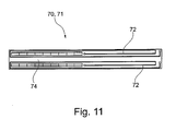
- Fig. 11 shows an excitation means 70 according to the invention.
- the excitation means 70 or electrode 71 comprises one or more coils 72 arranged in one single plane in a spiral manner.
- the coil 72 is arranged on a mounting plate 74.
Priority Applications (8)
| Application Number | Priority Date | Filing Date | Title |
|---|---|---|---|
| EP11007186.7A EP2565994B1 (de) | 2011-09-05 | 2011-09-05 | Laservorrichtung und -verfahren zum Markieren eines Gegenstands |
| ES11007186.7T ES2452529T3 (es) | 2011-09-05 | 2011-09-05 | Dispositivo láser y procedimiento para marcar un objeto |
| DK11007186.7T DK2565994T3 (en) | 2011-09-05 | 2011-09-05 | Laser device and method for marking an object |
| PCT/EP2012/003070 WO2013034215A1 (en) | 2011-09-05 | 2012-07-19 | Laser device and method for marking an object |
| CN201280043017.4A CN103765702B (zh) | 2011-09-05 | 2012-07-19 | 一种激光器设备以及一种用于标记物体的方法 |
| BR112014003931A BR112014003931A2 (pt) | 2011-09-05 | 2012-07-19 | dispositivo laser e método para a marcação de um objeto |
| EA201490244A EA024205B1 (ru) | 2011-09-05 | 2012-07-19 | Лазерное устройство и способ маркировки объекта |
| US14/342,504 US9664898B2 (en) | 2011-09-05 | 2012-07-19 | Laser device and method for marking an object |
Applications Claiming Priority (1)
| Application Number | Priority Date | Filing Date | Title |
|---|---|---|---|
| EP11007186.7A EP2565994B1 (de) | 2011-09-05 | 2011-09-05 | Laservorrichtung und -verfahren zum Markieren eines Gegenstands |
Publications (2)
| Publication Number | Publication Date |
|---|---|
| EP2565994A1 true EP2565994A1 (de) | 2013-03-06 |
| EP2565994B1 EP2565994B1 (de) | 2014-02-12 |
Family
ID=46724307
Family Applications (1)
| Application Number | Title | Priority Date | Filing Date |
|---|---|---|---|
| EP11007186.7A Not-in-force EP2565994B1 (de) | 2011-09-05 | 2011-09-05 | Laservorrichtung und -verfahren zum Markieren eines Gegenstands |
Country Status (8)
| Country | Link |
|---|---|
| US (1) | US9664898B2 (de) |
| EP (1) | EP2565994B1 (de) |
| CN (1) | CN103765702B (de) |
| BR (1) | BR112014003931A2 (de) |
| DK (1) | DK2565994T3 (de) |
| EA (1) | EA024205B1 (de) |
| ES (1) | ES2452529T3 (de) |
| WO (1) | WO2013034215A1 (de) |
Families Citing this family (3)
| Publication number | Priority date | Publication date | Assignee | Title |
|---|---|---|---|---|
| CA172005S (en) * | 2016-12-01 | 2017-08-11 | Riegl Laser Measurement Systems Gmbh | Laser scanner for surveying, for topographical and distance measurement |
| AU2020299104A1 (en) * | 2019-07-03 | 2021-12-23 | SEC Technologies, s.r.o. | Method for limiting the deflection of a laser beam from a laser head during temperature changes and a laser head |
| CN116174952B (zh) * | 2022-12-05 | 2023-09-22 | 无锡法维莱机械有限公司 | 一种具备水冷通道的激光焊接机机柜 |
Citations (4)
| Publication number | Priority date | Publication date | Assignee | Title |
|---|---|---|---|---|
| EP0157546A2 (de) * | 1984-04-05 | 1985-10-09 | Videojet Systems International, Inc. | Laser-Markierungsgerät |
| US4912718A (en) * | 1987-10-13 | 1990-03-27 | Hans Klingel | Device for a power laser |
| US5115446A (en) * | 1990-09-19 | 1992-05-19 | Trumpf Lasertechnik Gmbh | Device for a power laser |
| US5268921A (en) * | 1989-07-03 | 1993-12-07 | Mclellan Edward J | Multiple discharge gas laser apparatus |
Family Cites Families (277)
| Publication number | Priority date | Publication date | Assignee | Title |
|---|---|---|---|---|
| US2359780A (en) | 1938-10-29 | 1944-10-10 | Muffly Glenn | Refrigerating mechanism |
| GB1016576A (en) | 1962-08-22 | 1966-01-12 | Varian Associates | Optical maser |
| US3628175A (en) | 1963-11-29 | 1971-12-14 | Perkin Elmer Corp | Optical maser having concentric reservoirs and cylindrical resonator |
| US3564452A (en) | 1965-08-23 | 1971-02-16 | Spectra Physics | Laser with stable resonator |
| US3465358A (en) | 1966-07-21 | 1969-09-02 | Bell Telephone Labor Inc | Q-switched molecular laser |
| US3533012A (en) | 1967-02-10 | 1970-10-06 | Optics Technology Inc | Laser apparatus and method of aligning same |
| US3638137A (en) | 1969-01-10 | 1972-01-25 | Hughes Aircraft Co | Method of q-switching and mode locking a laser beam and structure |
| GB1269892A (en) | 1969-03-20 | 1972-04-06 | Messerschmitt Boelkow Blohm | Weapon system for the detection of and use against stationary or moving objects |
| US3596202A (en) | 1969-03-28 | 1971-07-27 | Bell Telephone Labor Inc | Carbon dioxide laser operating upon a vibrational-rotational transition |
| US3721915A (en) | 1969-09-19 | 1973-03-20 | Avco Corp | Electrically excited flowing gas laser and method of operation |
| US3646476A (en) | 1969-11-24 | 1972-02-29 | Coherent Radiation Lab | Pulsed gas ion laser |
| US3609584A (en) | 1970-02-11 | 1971-09-28 | Union Carbide Corp | Method and means for compensating thermal lensing in a laser system |
| US3602837A (en) | 1970-03-31 | 1971-08-31 | Us Army | Method and apparatus for exciting an ion laser at microwave frequencies |
| CH522287A (de) | 1970-04-13 | 1972-06-15 | Inst Angewandte Physik | Niederdruck-Gasentladungsrohr für Laser |
| US3801929A (en) | 1972-07-31 | 1974-04-02 | Asahi Optical Co Ltd | Gas laser apparatus having low temperature sensitivity |
| US3851272A (en) | 1973-01-02 | 1974-11-26 | Coherent Radiation | Gaseous laser with cathode forming optical resonator support and plasma tube envelope |
| US3900804A (en) | 1973-12-26 | 1975-08-19 | United Aircraft Corp | Multitube coaxial closed cycle gas laser system |
| US3919663A (en) | 1974-05-23 | 1975-11-11 | United Technologies Corp | Method and apparatus for aligning laser reflective surfaces |
| US4053851A (en) | 1975-07-10 | 1977-10-11 | The United States Of America As Represented By The United States Energy Research And Development Administration | Near 16 micron CO2 laser system |
| GB1495477A (en) | 1975-10-31 | 1977-12-21 | Taiwan Fan Shun Co Ltd | Drinking water supply apparatus for vehicles |
| IL49999A (en) | 1976-01-07 | 1979-12-30 | Mochida Pharm Co Ltd | Laser apparatus for operations |
| US4131782A (en) | 1976-05-03 | 1978-12-26 | Lasag Ag | Method of and apparatus for machining large numbers of holes of precisely controlled size by coherent radiation |
| US4122853A (en) | 1977-03-14 | 1978-10-31 | Spectra-Med | Infrared laser photocautery device |
| US4125755A (en) | 1977-06-23 | 1978-11-14 | Western Electric Co., Inc. | Laser welding |
| US4189687A (en) | 1977-10-25 | 1980-02-19 | Analytical Radiation Corporation | Compact laser construction |
| US4170405A (en) * | 1977-11-04 | 1979-10-09 | United Technologies Corporation | Resonator having coupled cavities with intercavity beam expansion elements |
| US4376496A (en) | 1979-10-12 | 1983-03-15 | The Coca-Cola Company | Post-mix beverage dispensing system syrup package, valving system, and carbonator therefor |
| JPS5764718A (en) | 1980-10-09 | 1982-04-20 | Hitachi Ltd | Laser beam printer |
| US4404571A (en) * | 1980-10-14 | 1983-09-13 | Canon Kabushiki Kaisha | Multibeam recording apparatus |
| JPS5843588A (ja) | 1981-09-09 | 1983-03-14 | Hitachi Ltd | レ−ザ発生装置 |
| US4500996A (en) | 1982-03-31 | 1985-02-19 | Coherent, Inc. | High power fundamental mode laser |
| US4477907A (en) | 1982-05-03 | 1984-10-16 | American Laser Corporation | Low power argon-ion gas laser |
| US4554666A (en) | 1982-11-24 | 1985-11-19 | Rca Corporation | High-energy, single longitudinal mode hybrid laser |
| WO1984002296A1 (en) | 1982-12-17 | 1984-06-21 | Inoue Japax Res | Laser machining apparatus |
| US4512639A (en) | 1983-07-05 | 1985-04-23 | The United States Of American As Represented By The Secretary Of The Army | Erectable large optic for outer space application |
| US4596018A (en) | 1983-10-07 | 1986-06-17 | Minnesota Laser Corp. | External electrode transverse high frequency gas discharge laser |
| FR2556262B1 (fr) | 1983-12-09 | 1987-02-20 | Ressencourt Hubert | La presente invention concerne un centre de faconnage de materiaux en feuilles a commande numerique |
| US4660209A (en) | 1983-12-29 | 1987-04-21 | Amada Engineering & Service Co., Inc. | High speed axial flow type gas laser oscillator |
| US4614913A (en) | 1984-04-30 | 1986-09-30 | The United States Of America As Represented By The Secretary Of The Army | Inherently boresighted laser weapon alignment subsystem |
| US4655547A (en) | 1985-04-09 | 1987-04-07 | Bell Communications Research, Inc. | Shaping optical pulses by amplitude and phase masking |
| US4744090A (en) | 1985-07-08 | 1988-05-10 | Trw Inc. | High-extraction efficiency annular resonator |
| DD256440A3 (de) | 1986-01-09 | 1988-05-11 | Halle Feinmech Werke Veb | Anordnung zur wellenlaengenselektion und internen leistungsmodulation der strahlung von hochleistungs-co tief 2-lasern |
| DD256439A3 (de) | 1986-01-09 | 1988-05-11 | Halle Feinmech Werke Veb | Verfahren zur steuerung der inneren und unterdrueckung der aeusseren strahlungsrueckkopplung eines co tief 2-hochleistungslasers |
| WO1987005750A1 (en) | 1986-03-12 | 1987-09-24 | Weiss Hardy P | Axial gas laser and process for stabilizing its operation |
| US4672620A (en) | 1986-05-14 | 1987-06-09 | Spectra-Physics, Inc. | Fast axial flow carbon dioxide laser |
| US4720618A (en) | 1986-08-07 | 1988-01-19 | Videojet Systems International, Inc. | Method and apparatus for equalizing power output in a laser marking system |
| US4727235A (en) | 1986-08-07 | 1988-02-23 | Videojet Systems International, Inc. | Method and apparatus for equalizing power output in a laser marking system |
| US4831333A (en) | 1986-09-11 | 1989-05-16 | Ltv Aerospace & Defense Co. | Laser beam steering apparatus |
| JPS6394695A (ja) | 1986-10-08 | 1988-04-25 | Nec Corp | ガスレ−ザ発振器 |
| US4779278A (en) | 1986-12-05 | 1988-10-18 | Laser Photonics, Inc. | Laser apparatus and method for discriminating against higher order modes |
| US4846550A (en) | 1987-01-07 | 1989-07-11 | Allied-Signal Inc. | Optical wedges used in beam expander for divergence control of laser |
| US5162940A (en) | 1987-03-06 | 1992-11-10 | The United States Of America As Represented By The Secretary Of The Air Force | Multiple energy level, multiple pulse rate laser source |
| WO1989006872A1 (en) | 1988-01-21 | 1989-07-27 | Siemens Aktiengesellschaft | Gas laser |
| US5012259A (en) | 1988-01-28 | 1991-04-30 | Konica Corporation | Color recorder with gas laser beam scanning |
| JP2592085B2 (ja) | 1988-02-09 | 1997-03-19 | マツダ株式会社 | アンチロック装置 |
| US4819246A (en) | 1988-03-23 | 1989-04-04 | Aerotech, Inc. | Single frequency adapter |
| US4770482A (en) | 1988-07-17 | 1988-09-13 | Gte Government Systems Corporation | Scanning system for optical transmitter beams |
| US5023886A (en) | 1988-12-01 | 1991-06-11 | Coherent, Inc. | High power laser with focusing mirror sets |
| US5052017A (en) | 1988-12-01 | 1991-09-24 | Coherent, Inc. | High power laser with focusing mirror sets |
| US4953176A (en) | 1989-03-07 | 1990-08-28 | Spectra-Physics | Angular optical cavity alignment adjustment utilizing variable distribution cooling |
| US4958900A (en) | 1989-03-27 | 1990-09-25 | General Electric Company | Multi-fiber holder for output coupler and methods using same |
| GB8912765D0 (en) | 1989-06-02 | 1989-07-19 | Lumonics Ltd | A laser |
| DE3937370A1 (de) | 1989-11-09 | 1991-05-16 | Otto Bihler | Laser |
| US4991149A (en) | 1989-12-07 | 1991-02-05 | The United States Of America As Represented By The Secretary Of The Navy | Underwater object detection system |
| US5065405A (en) | 1990-01-24 | 1991-11-12 | Synrad, Incorporated | Sealed-off, RF-excited gas lasers and method for their manufacture |
| US5109149A (en) | 1990-03-15 | 1992-04-28 | Albert Leung | Laser, direct-write integrated circuit production system |
| US5214658A (en) | 1990-07-27 | 1993-05-25 | Ion Laser Technology | Mixed gas ion laser |
| DE4029187C2 (de) | 1990-09-14 | 2001-08-16 | Trumpf Lasertechnik Gmbh | Längsgeströmter CO¶2¶-Laser |
| GB2249843A (en) | 1990-10-25 | 1992-05-20 | Robert Peter Sunman | Image production |
| US5653900A (en) | 1991-01-17 | 1997-08-05 | United Distillers Plc | Dynamic laser marking |
| US5229574A (en) | 1991-10-15 | 1993-07-20 | Videojet Systems International, Inc. | Print quality laser marker apparatus |
| US5229573A (en) | 1991-10-15 | 1993-07-20 | Videojet Systems International, Inc. | Print quality laser marker apparatus |
| JPH05129678A (ja) | 1991-10-31 | 1993-05-25 | Shibuya Kogyo Co Ltd | レーザマーキング装置 |
| CA2123008C (en) | 1991-11-06 | 2003-01-21 | Shui T. Lai | Corneal surgery device and method |
| US5199042A (en) | 1992-01-10 | 1993-03-30 | Litton Systems, Inc. | Unstable laser apparatus |
| DE4300700A1 (en) | 1992-01-14 | 1993-07-29 | Boreal Laser Inc | Carbon di:oxide plate laser group arrangement - has channel between wave-conducting electrode surfaces subdivided into multiple parallel laser resonators |
| US5572538A (en) | 1992-01-20 | 1996-11-05 | Miyachi Technos Corporation | Laser apparatus and accessible, compact cooling system thereof having interchangeable flow restricting members |
| JP2872855B2 (ja) | 1992-02-19 | 1999-03-24 | ファナック株式会社 | レーザ発振器 |
| DE4212390A1 (de) | 1992-04-13 | 1993-10-14 | Baasel Carl Lasertech | Strahlführungssystem für mehrere Laserstrahlen |
| US5337325A (en) | 1992-05-04 | 1994-08-09 | Photon Imaging Corp | Semiconductor, light-emitting devices |
| US5339737B1 (en) | 1992-07-20 | 1997-06-10 | Presstek Inc | Lithographic printing plates for use with laser-discharge imaging apparatus |
| JP2980788B2 (ja) | 1992-10-21 | 1999-11-22 | 三菱電機株式会社 | レーザ装置 |
| JP2725569B2 (ja) | 1992-11-18 | 1998-03-11 | 松下電器産業株式会社 | レーザ発振器 |
| US5274661A (en) | 1992-12-07 | 1993-12-28 | Spectra Physics Lasers, Inc. | Thin film dielectric coating for laser resonator |
| JP3022016B2 (ja) | 1992-12-28 | 2000-03-15 | 松下電器産業株式会社 | 軸流形レーザ発振器 |
| US5729568A (en) | 1993-01-22 | 1998-03-17 | Deutsche Forschungsanstalt Fuer Luft-Und Raumfahrt E.V. | Power-controlled, fractal laser system |
| US5294774A (en) | 1993-08-03 | 1994-03-15 | Videojet Systems International, Inc. | Laser marker system |
| US5431199A (en) | 1993-11-30 | 1995-07-11 | Benjey, Robert P | Redundant seal for vehicle filler neck |
| JPH07211972A (ja) | 1994-01-20 | 1995-08-11 | Fanuc Ltd | レーザ発振器 |
| DE4402054A1 (de) | 1994-01-25 | 1995-07-27 | Zeiss Carl Fa | Gaslaser und Gasnachweis damit |
| US5386427A (en) | 1994-02-10 | 1995-01-31 | Massachusetts Institute Of Technology | Thermally controlled lenses for lasers |
| EP0745282B1 (de) | 1994-02-15 | 1999-05-12 | Coherent, Inc. | System zur minimisierung der durch thermisch induzierte doppelbrechung bedingten depolarisation eines laserstrahls |
| JPH07246488A (ja) | 1994-03-11 | 1995-09-26 | Fanuc Ltd | レーザ加工装置 |
| US5767477A (en) | 1994-03-23 | 1998-06-16 | Domino Printing Sciences Plc | Laser marking apparatus for marking twin-line messages |
| US5568306A (en) | 1994-10-17 | 1996-10-22 | Leonard Tachner | Laser beam control and imaging system |
| JPH08139391A (ja) | 1994-11-02 | 1996-05-31 | Fanuc Ltd | レーザ共振器 |
| US5929337A (en) | 1994-11-11 | 1999-07-27 | M & A Packaging Services Limited | Non-mechanical contact ultrasound system for monitoring contents of a moving container |
| US5550853A (en) | 1994-12-21 | 1996-08-27 | Laser Physics, Inc. | Integral laser head and power supply |
| US5659561A (en) | 1995-06-06 | 1997-08-19 | University Of Central Florida | Spatial solitary waves in bulk quadratic nonlinear materials and their applications |
| US5689363A (en) | 1995-06-12 | 1997-11-18 | The Regents Of The University Of California | Long-pulse-width narrow-bandwidth solid state laser |
| JP3427573B2 (ja) | 1995-06-27 | 2003-07-22 | 松下電器産業株式会社 | マイクロ波励起ガスレーザ発振装置 |
| US5646907A (en) | 1995-08-09 | 1997-07-08 | The United States Of America As Represented By The Secretary Of The Navy | Method and system for detecting objects at or below the water's surface |
| DE29514319U1 (de) | 1995-09-07 | 1997-01-16 | Sator Alexander Paul | Vorrichtung zum Beschriften von Gegenständen |
| US5592504A (en) | 1995-10-10 | 1997-01-07 | Cameron; Harold A. | Transversely excited non waveguide RF gas laser configuration |
| US5661746A (en) | 1995-10-17 | 1997-08-26 | Universal Laser Syatems, Inc. | Free-space gas slab laser |
| US5682262A (en) | 1995-12-13 | 1997-10-28 | Massachusetts Institute Of Technology | Method and device for generating spatially and temporally shaped optical waveforms |
| US5720894A (en) | 1996-01-11 | 1998-02-24 | The Regents Of The University Of California | Ultrashort pulse high repetition rate laser system for biological tissue processing |
| FR2748519B1 (fr) | 1996-05-10 | 1998-06-26 | Valeo Thermique Moteur Sa | Dispositif de refroidissement d'un moteur avec reservoir de fluide thermiquement isole |
| US5837962A (en) | 1996-07-15 | 1998-11-17 | Overbeck; James W. | Faster laser marker employing acousto-optic deflection |
| US5808268A (en) | 1996-07-23 | 1998-09-15 | International Business Machines Corporation | Method for marking substrates |
| US6050486A (en) | 1996-08-23 | 2000-04-18 | Pitney Bowes Inc. | Electronic postage meter system separable printer and accounting arrangement incorporating partition of indicia and accounting information |
| DE19634190C2 (de) | 1996-08-23 | 2002-01-31 | Baasel Carl Lasertech | Mehrkopf-Lasergravuranlage |
| US5864430A (en) | 1996-09-10 | 1999-01-26 | Sandia Corporation | Gaussian beam profile shaping apparatus, method therefor and evaluation thereof |
| US6421159B1 (en) | 1996-09-11 | 2002-07-16 | The Domino Corporation | Multiple beam laser marking apparatus |
| US6064034A (en) | 1996-11-22 | 2000-05-16 | Anolaze Corporation | Laser marking process for vitrification of bricks and other vitrescent objects |
| US5815523A (en) | 1996-11-27 | 1998-09-29 | Mcdonnell Douglas Corporation | Variable power helix laser amplifier and laser |
| JP3932207B2 (ja) | 1997-03-14 | 2007-06-20 | デマリア エレクトロオプティックス システムズ アイエヌシー | 無線周波数励起導波レーザ |
| US6141030A (en) | 1997-04-24 | 2000-10-31 | Konica Corporation | Laser exposure unit including plural laser beam sources differing in wavelength |
| US6122562A (en) | 1997-05-05 | 2000-09-19 | Applied Materials, Inc. | Method and apparatus for selectively marking a semiconductor wafer |
| FR2766115B1 (fr) | 1997-07-18 | 1999-08-27 | Commissariat Energie Atomique | Dispositif et procede de decoupe a distance etendue par laser, en mode impulsionnel |
| DE19734715A1 (de) | 1997-08-11 | 1999-02-25 | Lambda Physik Gmbh | Vorrichtung zum Spülen des Strahlenganges eines UV-Laserstrahles |
| US6069843A (en) | 1997-08-28 | 2000-05-30 | Northeastern University | Optical pulse induced acoustic mine detection |
| US6263007B1 (en) | 1998-03-23 | 2001-07-17 | T & S Team Incorporated | Pulsed discharge gas laser having non-integral supply reservoir |
| JP3041599B2 (ja) | 1998-05-14 | 2000-05-15 | セイコーインスツルメンツ株式会社 | 座標出し光学式観察装置および位置情報蓄積方法 |
| US6898216B1 (en) | 1999-06-30 | 2005-05-24 | Lambda Physik Ag | Reduction of laser speckle in photolithography by controlled disruption of spatial coherence of laser beam |
| US6181728B1 (en) | 1998-07-02 | 2001-01-30 | General Scanning, Inc. | Controlling laser polarization |
| US6057871A (en) | 1998-07-10 | 2000-05-02 | Litton Systems, Inc. | Laser marking system and associated microlaser apparatus |
| DE19840926B4 (de) | 1998-09-08 | 2013-07-11 | Hell Gravure Systems Gmbh & Co. Kg | Anordnung zur Materialbearbeitung mittels Laserstrahlen und deren Verwendung |
| EP1051722A1 (de) | 1998-11-02 | 2000-11-15 | Koninklijke Philips Electronics N.V. | Laser-beleuchtungsanordnung für eine kathodenstrahlröhre |
| US6229940B1 (en) | 1998-11-30 | 2001-05-08 | Mcdonnell Douglas Corporation | Incoherent fiber optic laser system |
| TW444247B (en) | 1999-01-29 | 2001-07-01 | Toshiba Corp | Laser beam irradiating device, manufacture of non-single crystal semiconductor film, and manufacture of liquid crystal display device |
| JP2003515243A (ja) | 1999-02-03 | 2003-04-22 | トルンプフ レーザーテヒニク ゲゼルシャフト ミット ベシュレンクテル ハフツング | レーザビームの全横断面にわたつてレーザ光の強度分布を変化させる装置を備えたレーザ |
| US6678291B2 (en) | 1999-12-15 | 2004-01-13 | Lambda Physik Ag | Molecular fluorine laser |
| US6356575B1 (en) | 1999-07-06 | 2002-03-12 | Raytheon Company | Dual cavity multifunction laser system |
| JP2001023918A (ja) | 1999-07-08 | 2001-01-26 | Nec Corp | 半導体薄膜形成装置 |
| US6335943B1 (en) | 1999-07-27 | 2002-01-01 | Lockheed Martin Corporation | System and method for ultrasonic laser testing using a laser source to generate ultrasound having a tunable wavelength |
| US6944201B2 (en) | 1999-07-30 | 2005-09-13 | High Q Laser Production Gmbh | Compact ultra fast laser |
| US20060249491A1 (en) | 1999-09-01 | 2006-11-09 | Hell Gravure Systems Gmbh | Laser radiation source |
| US6833911B2 (en) | 1999-10-08 | 2004-12-21 | Identification Dynamics, Inc. | Method and apparatus for reading firearm microstamping |
| US6886284B2 (en) | 1999-10-08 | 2005-05-03 | Identification Dynamics, Llc | Firearm microstamping and micromarking insert for stamping a firearm identification code and serial number into cartridge shell casings and projectiles |
| US6420675B1 (en) | 1999-10-08 | 2002-07-16 | Nanovia, Lp | Control system for ablating high-density array of vias or indentation in surface of object |
| US6310701B1 (en) | 1999-10-08 | 2001-10-30 | Nanovia Lp | Method and apparatus for ablating high-density array of vias or indentation in surface of object |
| US6653593B2 (en) | 1999-10-08 | 2003-11-25 | Nanovia, Lp | Control system for ablating high-density array of vias or indentation in surface of object |
| US6256121B1 (en) | 1999-10-08 | 2001-07-03 | Nanovia, Lp | Apparatus for ablating high-density array of vias or indentation in surface of object |
| US6735232B2 (en) | 2000-01-27 | 2004-05-11 | Lambda Physik Ag | Laser with versatile output energy |
| JP2001276986A (ja) | 2000-03-29 | 2001-10-09 | Nec Corp | レーザ加工装置及び方法 |
| EP1143584A3 (de) | 2000-03-31 | 2003-04-23 | Matsushita Electric Industrial Co., Ltd. | Vielfachhalbleiterlaser |
| US6791592B2 (en) | 2000-04-18 | 2004-09-14 | Laserink | Printing a code on a product |
| US7394591B2 (en) | 2000-05-23 | 2008-07-01 | Imra America, Inc. | Utilization of Yb: and Nd: mode-locked oscillators in solid-state short pulse laser systems |
| US6605799B2 (en) | 2000-05-25 | 2003-08-12 | Westar Photonics | Modulation of laser energy with a predefined pattern |
| WO2001093380A1 (fr) | 2000-05-30 | 2001-12-06 | Matsushita Electric Industrial Co., Ltd. | Dispositif d'oscillation laser |
| US6904073B2 (en) | 2001-01-29 | 2005-06-07 | Cymer, Inc. | High power deep ultraviolet laser with long life optics |
| DE20011508U1 (de) | 2000-06-30 | 2000-10-12 | Termotek Laserkuehlung Gmbh | Kühlvorrichtung für einen Laser |
| JP2002045371A (ja) | 2000-08-01 | 2002-02-12 | Nidek Co Ltd | レーザ治療装置 |
| DE10043269C2 (de) | 2000-08-29 | 2002-10-24 | Jenoptik Jena Gmbh | Diodengepumpter Laserverstärker |
| US6585161B1 (en) * | 2000-08-30 | 2003-07-01 | Psc Scanning, Inc. | Dense pattern optical scanner |
| EP1184946B1 (de) | 2000-08-31 | 2010-08-18 | Trumpf Laser- und Systemtechnik GmbH | Gaslaser |
| EP1332494A4 (de) | 2000-09-21 | 2005-04-20 | Gsi Lumonics Corp | Digitales steuer-servosystem |
| DE10047020C1 (de) | 2000-09-22 | 2002-02-07 | Trumpf Lasertechnik Gmbh | Laser mit wenigstens zwei Elektrodenrohren und einer Kühleinrichtung, Verfahren zur Herstellung eines Lasers sowie Vorrichtung zur Durchführung eines derartigen Verfahrens |
| US20020061045A1 (en) | 2000-11-21 | 2002-05-23 | Access Laser Company | Portable low-power gas discharge laser |
| US6693930B1 (en) | 2000-12-12 | 2004-02-17 | Kla-Tencor Technologies Corporation | Peak power and speckle contrast reduction for a single laser pulse |
| DE50004515D1 (de) | 2000-12-16 | 2003-12-24 | Trumpf Lasertechnik Gmbh | Koaxialer Laser mit einer Einrichtung zur Strahlformung eines Laserstrahls |
| US7496831B2 (en) | 2001-02-22 | 2009-02-24 | International Business Machines Corporation | Method to reformat regions with cluttered hyperlinks |
| EP1370383A4 (de) | 2001-03-19 | 2007-06-27 | Nutfield Technologies Inc | Monolithische, keramische laserkonstruktion und herstellungsverfahren dafür |
| US6370884B1 (en) | 2001-03-30 | 2002-04-16 | Maher I. Kelada | Thermoelectric fluid cooling cartridge |
| US6768765B1 (en) | 2001-06-07 | 2004-07-27 | Lambda Physik Ag | High power excimer or molecular fluorine laser system |
| AU2002311597A1 (en) | 2001-06-13 | 2002-12-23 | Orbotech Ltd. | Multi-beam micro-machining system and method |
| US6804269B2 (en) | 2001-06-19 | 2004-10-12 | Hitachi Via Mechanics, Ltd. | Laser beam delivery system with trepanning module |
| US6915654B2 (en) | 2001-06-20 | 2005-07-12 | Ross Johnson | Portable cooling mechanism |
| US6914232B2 (en) | 2001-10-26 | 2005-07-05 | Bennett Optical Research, Inc. | Device to control laser spot size |
| JP2006502558A (ja) | 2001-11-07 | 2006-01-19 | アプライド マテリアルズ インコーポレイテッド | 光学式スポット格子アレイ印刷装置 |
| DE10202036A1 (de) | 2002-01-18 | 2003-07-31 | Zeiss Carl Meditec Ag | Femtosekunden Lasersystem zur präzisen Bearbeitung von Material und Gewebe |
| US6804287B2 (en) | 2002-02-02 | 2004-10-12 | The Regents Of The University Of Colorado, A Body Corporate | Ultrashort pulse amplification in cryogenically cooled amplifiers |
| US20040028108A1 (en) | 2002-02-07 | 2004-02-12 | Govorkov Sergei V. | Solid-state diode pumped laser employing oscillator-amplifier |
| US6750421B2 (en) | 2002-02-19 | 2004-06-15 | Gsi Lumonics Ltd. | Method and system for laser welding |
| US6756563B2 (en) | 2002-03-07 | 2004-06-29 | Orbotech Ltd. | System and method for forming holes in substrates containing glass |
| US6826219B2 (en) | 2002-03-14 | 2004-11-30 | Gigatera Ag | Semiconductor saturable absorber device, and laser |
| US7058100B2 (en) | 2002-04-18 | 2006-06-06 | The Boeing Company | Systems and methods for thermal management of diode-pumped solid-state lasers |
| US20030219094A1 (en) * | 2002-05-21 | 2003-11-27 | Basting Dirk L. | Excimer or molecular fluorine laser system with multiple discharge units |
| JPWO2004017392A1 (ja) | 2002-08-13 | 2005-12-08 | 株式会社東芝 | レーザ照射方法 |
| US20040202220A1 (en) | 2002-11-05 | 2004-10-14 | Gongxue Hua | Master oscillator-power amplifier excimer laser system |
| US6903824B2 (en) | 2002-12-20 | 2005-06-07 | Eastman Kodak Company | Laser sensitometer |
| US7145926B2 (en) | 2003-01-24 | 2006-12-05 | Peter Vitruk | RF excited gas laser |
| US20050094697A1 (en) | 2003-01-30 | 2005-05-05 | Rofin Sinar Laser Gmbh | Stripline laser |
| TWI248244B (en) | 2003-02-19 | 2006-01-21 | J P Sercel Associates Inc | System and method for cutting using a variable astigmatic focal beam spot |
| US7321105B2 (en) | 2003-02-21 | 2008-01-22 | Lsp Technologies, Inc. | Laser peening of dovetail slots by fiber optical and articulate arm beam delivery |
| US7408687B2 (en) | 2003-04-10 | 2008-08-05 | Hitachi Via Mechanics (Usa), Inc. | Beam shaping prior to harmonic generation for increased stability of laser beam shaping post harmonic generation with integrated automatic displacement and thermal beam drift compensation |
| US7499207B2 (en) | 2003-04-10 | 2009-03-03 | Hitachi Via Mechanics, Ltd. | Beam shaping prior to harmonic generation for increased stability of laser beam shaping post harmonic generation with integrated automatic displacement and thermal beam drift compensation |
| WO2004097465A2 (en) | 2003-04-24 | 2004-11-11 | Bae Systems Information And Electronic Systems Integration Inc. | Singlet telescopes with controllable ghosts for laser beam forming |
| US20060287697A1 (en) | 2003-05-28 | 2006-12-21 | Medcool, Inc. | Methods and apparatus for thermally activating a console of a thermal delivery system |
| GB0313887D0 (en) | 2003-06-16 | 2003-07-23 | Gsi Lumonics Ltd | Monitoring and controlling of laser operation |
| US6856509B2 (en) | 2003-07-14 | 2005-02-15 | Jen-Cheng Lin | Cartridge assembly of a water cooled radiator |
| US7521651B2 (en) * | 2003-09-12 | 2009-04-21 | Orbotech Ltd | Multiple beam micro-machining system and method |
| US7364952B2 (en) | 2003-09-16 | 2008-04-29 | The Trustees Of Columbia University In The City Of New York | Systems and methods for processing thin films |
| US6894785B2 (en) | 2003-09-30 | 2005-05-17 | Cymer, Inc. | Gas discharge MOPA laser spectral analysis module |
| CN100544877C (zh) | 2003-10-17 | 2009-09-30 | 通明国际科技公司 | 活动扫描场 |
| US20050205778A1 (en) | 2003-10-17 | 2005-09-22 | Gsi Lumonics Corporation | Laser trim motion, calibration, imaging, and fixturing techniques |
| EP1528645B1 (de) | 2003-10-30 | 2011-02-16 | Metal Improvement Company, LLC. | Relay Teleskop, Laserverstärker, und Laserschockbestrahlungsverfahren und dessen Vorrichtung |
| US7291805B2 (en) | 2003-10-30 | 2007-11-06 | The Regents Of The University Of California | Target isolation system, high power laser and laser peening method and system using same |
| JP2005144487A (ja) | 2003-11-13 | 2005-06-09 | Seiko Epson Corp | レーザ加工装置及びレーザ加工方法 |
| AT412829B (de) | 2003-11-13 | 2005-07-25 | Femtolasers Produktions Gmbh | Kurzpuls-laservorrichtung |
| JP4344224B2 (ja) | 2003-11-21 | 2009-10-14 | 浜松ホトニクス株式会社 | 光学マスクおよびmopaレーザ装置 |
| US7376160B2 (en) | 2003-11-24 | 2008-05-20 | Raytheon Company | Slab laser and method with improved and directionally homogenized beam quality |
| US7046267B2 (en) | 2003-12-19 | 2006-05-16 | Markem Corporation | Striping and clipping correction |
| US20050190809A1 (en) | 2004-01-07 | 2005-09-01 | Spectra-Physics, Inc. | Ultraviolet, narrow linewidth laser system |
| US7199330B2 (en) | 2004-01-20 | 2007-04-03 | Coherent, Inc. | Systems and methods for forming a laser beam having a flat top |
| ATE415643T1 (de) | 2004-01-23 | 2008-12-15 | Gsi Group Corp | System und verfahren zum optimieren der zeichenmarkierungsleistung |
| JP2005268445A (ja) | 2004-03-17 | 2005-09-29 | Hamamatsu Photonics Kk | 半導体レーザ装置 |
| JP2005294393A (ja) | 2004-03-31 | 2005-10-20 | Fanuc Ltd | レーザ発振器 |
| US7711013B2 (en) | 2004-03-31 | 2010-05-04 | Imra America, Inc. | Modular fiber-based chirped pulse amplification system |
| US7486705B2 (en) | 2004-03-31 | 2009-02-03 | Imra America, Inc. | Femtosecond laser processing system with process parameters, controls and feedback |
| US7565705B2 (en) | 2004-05-11 | 2009-07-28 | Biocool Technologies, Llc | Garment for a cooling and hydration system |
| US20110102537A1 (en) | 2004-05-19 | 2011-05-05 | Neil Griffin | Thermal printing with laser activation |
| JP4182034B2 (ja) | 2004-08-05 | 2008-11-19 | ファナック株式会社 | 切断加工用レーザ装置 |
| ATE343148T1 (de) | 2004-09-30 | 2006-11-15 | Trumpf Laser Gmbh & Co Kg | Vorrichtung zur fokussierung eines laserstrahls |
| US20060092995A1 (en) | 2004-11-01 | 2006-05-04 | Chromaplex, Inc. | High-power mode-locked laser system |
| US7204298B2 (en) | 2004-11-24 | 2007-04-17 | Lucent Technologies Inc. | Techniques for microchannel cooling |
| JP3998067B2 (ja) | 2004-11-29 | 2007-10-24 | オムロンレーザーフロント株式会社 | 固体レーザ発振器 |
| US20060114956A1 (en) | 2004-11-30 | 2006-06-01 | Sandstrom Richard L | High power high pulse repetition rate gas discharge laser system bandwidth management |
| US7346427B2 (en) | 2005-01-14 | 2008-03-18 | Flymg J, Inc. | Collecting liquid product volume data at a dispenser |
| US7295948B2 (en) | 2005-01-15 | 2007-11-13 | Jetter Heinz L | Laser system for marking tires |
| US7394479B2 (en) | 2005-03-02 | 2008-07-01 | Marken Corporation | Pulsed laser printing |
| US7430230B2 (en) | 2005-04-07 | 2008-09-30 | The Boeing Company | Tube solid-state laser |
| DE102005024931B3 (de) | 2005-05-23 | 2007-01-11 | Ltb-Lasertechnik Gmbh | Transversal elektrisch angeregter Gasentladungslaser zur Erzeugung von Lichtpulsen mit hoher Pulsfolgefrequenz und Verfahren zur Herstellung |
| US7334744B1 (en) | 2005-05-23 | 2008-02-26 | Gentry Dawson | Portable mister and cooling assembly for outdoor use |
| US8278590B2 (en) | 2005-05-27 | 2012-10-02 | Resonetics, LLC | Apparatus for minimizing a heat affected zone during laser micro-machining |
| DE112006001842B4 (de) | 2005-07-12 | 2017-06-14 | Novanta Corp. | Einheit und Verfahren für Hochleistungs-Laserbearbeitung |
| US20100220750A1 (en) | 2005-07-19 | 2010-09-02 | James Hayden Brownell | Terahertz Laser Components And Associated Methods |
| JP2007032869A (ja) | 2005-07-22 | 2007-02-08 | Fujitsu Ltd | 冷却装置および冷却方法 |
| JP2007029972A (ja) | 2005-07-25 | 2007-02-08 | Fanuc Ltd | レーザ加工装置 |
| WO2007042913A2 (en) | 2005-10-11 | 2007-04-19 | Kilolambda Technologies Ltd. | Optical power limiting and switching combined device and a method for protecting imaging and non-imaging sensors |
| US20070098024A1 (en) | 2005-10-28 | 2007-05-03 | Laserscope | High power, end pumped laser with off-peak pumping |
| KR101371265B1 (ko) | 2005-12-16 | 2014-03-07 | 가부시키가이샤 한도오따이 에네루기 켄큐쇼 | 레이저 조사 장치, 레이저 조사 방법, 및 반도체 장치 제조방법 |
| US20090312676A1 (en) | 2006-02-02 | 2009-12-17 | Tylerton International Inc. | Metabolic Sink |
| JP2007212118A (ja) | 2006-02-08 | 2007-08-23 | Makoto Fukada | 冷感度を高めた水冷式冷風扇 |
| US7543912B2 (en) | 2006-03-01 | 2009-06-09 | Lexmark International, Inc. | Unitary wick retainer and biasing device retainer for micro-fluid ejection head replaceable cartridge |
| US20070235458A1 (en) | 2006-04-10 | 2007-10-11 | Mann & Hummel Gmbh | Modular liquid reservoir |
| WO2007145702A2 (en) | 2006-04-10 | 2007-12-21 | Board Of Trustees Of Michigan State University | Laser material processing systems and methods with, in particular, use of a hollow waveguide for broadening the bandwidth of the pulse above 20 nm |
| US20070247499A1 (en) | 2006-04-19 | 2007-10-25 | Anderson Jr James D | Multi-function thermoplastic elastomer layer for replaceable ink tank |
| US7545838B2 (en) | 2006-06-12 | 2009-06-09 | Coherent, Inc. | Incoherent combination of laser beams |
| JP4146867B2 (ja) | 2006-06-22 | 2008-09-10 | ファナック株式会社 | ガスレーザ発振器 |
| US7626152B2 (en) | 2006-08-16 | 2009-12-01 | Raytheon Company | Beam director and control system for a high energy laser within a conformal window |
| CN100547863C (zh) | 2006-10-20 | 2009-10-07 | 香港理工大学 | 光纤气体激光器和具有该激光器的光纤型环形激光陀螺仪 |
| US7784348B2 (en) | 2006-12-22 | 2010-08-31 | Lockheed Martin Corporation | Articulated robot for laser ultrasonic inspection |
| US20090323739A1 (en) | 2006-12-22 | 2009-12-31 | Uv Tech Systems | Laser optical system |
| US7733930B2 (en) | 2007-04-10 | 2010-06-08 | Northrop Grumman Systems Corporation | Error control for high-power laser system employing diffractive optical element beam combiner with tilt error control |
| US7729398B2 (en) | 2007-04-10 | 2010-06-01 | Northrop Grumman Systems Corporation | Error control for high-power laser system employing diffractive optical element beam combiner |
| DE102007023017B4 (de) | 2007-05-15 | 2011-06-01 | Thyssenkrupp Lasertechnik Gmbh | Vorrichtung und Verfahren zum Herstellen von Tailored Blanks |
| US20080297912A1 (en) | 2007-06-01 | 2008-12-04 | Electro Scientific Industries, Inc., An Oregon Corporation | Vario-astigmatic beam expander |
| JP5129678B2 (ja) | 2007-07-18 | 2013-01-30 | 株式会社クボタ | 作業車 |
| US7924894B2 (en) | 2008-01-18 | 2011-04-12 | Northrop Grumman Systems Corporation | Digital piston error control for high-power laser system employing diffractive optical element beam combiner |
| US7756169B2 (en) | 2008-01-23 | 2010-07-13 | Northrop Grumman Systems Corporation | Diffractive method for control of piston error in coherent phased arrays |
| US8126028B2 (en) | 2008-03-31 | 2012-02-28 | Novasolar Holdings Limited | Quickly replaceable processing-laser modules and subassemblies |
| GB0809003D0 (en) | 2008-05-17 | 2008-06-25 | Rumsby Philip T | Method and apparatus for laser process improvement |
| GB2460648A (en) | 2008-06-03 | 2009-12-09 | M Solv Ltd | Method and apparatus for laser focal spot size control |
| DE102008030868A1 (de) | 2008-06-30 | 2009-12-31 | Krones Ag | Vorrichtung zum Beschriften von Behältnissen |
| US8038878B2 (en) | 2008-11-26 | 2011-10-18 | Mann+Hummel Gmbh | Integrated filter system for a coolant reservoir and method |
| US8729426B2 (en) | 2008-12-13 | 2014-05-20 | M-Solv Ltd. | Method and apparatus for laser machining relatively narrow and relatively wide structures |
| GB0900036D0 (en) | 2009-01-03 | 2009-02-11 | M Solv Ltd | Method and apparatus for forming grooves with complex shape in the surface of apolymer |
| CA2749670A1 (en) | 2009-02-04 | 2010-08-12 | The General Hospital Corporation | Apparatus and method for utilization of a high-speed optical wavelength tuning source |
| US20100206882A1 (en) | 2009-02-13 | 2010-08-19 | Wessels Timothy J | Multi chamber coolant tank |
| WO2010102155A1 (en) | 2009-03-04 | 2010-09-10 | Aaren Scientific Inc. | System for forming and modifying lenses and lenses formed thereby |
| US8184363B2 (en) | 2009-08-07 | 2012-05-22 | Northrop Grumman Systems Corporation | All-fiber integrated high power coherent beam combination |
| US8514485B2 (en) | 2009-08-07 | 2013-08-20 | Northrop Grumman Systems Corporation | Passive all-fiber integrated high power coherent beam combination |
| US8184361B2 (en) | 2009-08-07 | 2012-05-22 | Northrop Grumman Systems Corporation | Integrated spectral and all-fiber coherent beam combination |
| US8320056B2 (en) | 2009-08-20 | 2012-11-27 | Lawrence Livermore National Security, Llc | Spatial filters for high average power lasers |
| US8212178B1 (en) | 2009-09-28 | 2012-07-03 | Klein Tools, Inc. | Method and system for marking a material using a laser marking system |
| US8337618B2 (en) | 2009-10-26 | 2012-12-25 | Samsung Display Co., Ltd. | Silicon crystallization system and silicon crystallization method using laser |
| JP2011156574A (ja) | 2010-02-02 | 2011-08-18 | Hitachi High-Technologies Corp | レーザ加工用フォーカス装置、レーザ加工装置及びソーラパネル製造方法 |
| JP5634088B2 (ja) | 2010-03-17 | 2014-12-03 | キヤノン株式会社 | インクジェット記録装置およびインクタンク |
| CN101807772B (zh) * | 2010-04-12 | 2011-07-20 | 中国科学院长春光学精密机械与物理研究所 | 高功率tea气体激光器环形谐振激光腔 |
| US10072971B2 (en) | 2010-04-16 | 2018-09-11 | Metal Improvement Company, Llc | Flexible beam delivery system for high power laser systems |
| US8233511B2 (en) | 2010-05-18 | 2012-07-31 | Lawrence Livermore National Security, Llc | Method and system for modulation of gain suppression in high average power laser systems |
| US8432691B2 (en) | 2010-10-28 | 2013-04-30 | Asetek A/S | Liquid cooling system for an electronic system |
| EP2565673B1 (de) | 2011-09-05 | 2013-11-13 | ALLTEC Angewandte Laserlicht Technologie Gesellschaft mit beschränkter Haftung | Vorrichtung und Verfahren zum Markieren eines Objekts mit Hilfe eines Laserstrahls |
| ES2544269T3 (es) | 2011-09-05 | 2015-08-28 | ALLTEC Angewandte Laserlicht Technologie Gesellschaft mit beschränkter Haftung | Aparato de marcado con una pluralidad de láseres de gas con tubos de resonancia y medios de deflexión ajustables individualmente |
| EP2564972B1 (de) | 2011-09-05 | 2015-08-26 | ALLTEC Angewandte Laserlicht Technologie Gesellschaft mit beschränkter Haftung | Markierungsvorrichtung mith mehreren Lasern, Deflektionmitteln und Telescopikmitteln für jeden Laserstrahl |
-
2011
- 2011-09-05 EP EP11007186.7A patent/EP2565994B1/de not_active Not-in-force
- 2011-09-05 DK DK11007186.7T patent/DK2565994T3/en active
- 2011-09-05 ES ES11007186.7T patent/ES2452529T3/es active Active
-
2012
- 2012-07-19 WO PCT/EP2012/003070 patent/WO2013034215A1/en active Application Filing
- 2012-07-19 BR BR112014003931A patent/BR112014003931A2/pt not_active IP Right Cessation
- 2012-07-19 CN CN201280043017.4A patent/CN103765702B/zh not_active Expired - Fee Related
- 2012-07-19 US US14/342,504 patent/US9664898B2/en active Active
- 2012-07-19 EA EA201490244A patent/EA024205B1/ru not_active IP Right Cessation
Patent Citations (4)
| Publication number | Priority date | Publication date | Assignee | Title |
|---|---|---|---|---|
| EP0157546A2 (de) * | 1984-04-05 | 1985-10-09 | Videojet Systems International, Inc. | Laser-Markierungsgerät |
| US4912718A (en) * | 1987-10-13 | 1990-03-27 | Hans Klingel | Device for a power laser |
| US5268921A (en) * | 1989-07-03 | 1993-12-07 | Mclellan Edward J | Multiple discharge gas laser apparatus |
| US5115446A (en) * | 1990-09-19 | 1992-05-19 | Trumpf Lasertechnik Gmbh | Device for a power laser |
Also Published As
| Publication number | Publication date |
|---|---|
| US20140202998A1 (en) | 2014-07-24 |
| BR112014003931A2 (pt) | 2017-03-14 |
| ES2452529T3 (es) | 2014-04-01 |
| EP2565994B1 (de) | 2014-02-12 |
| US9664898B2 (en) | 2017-05-30 |
| EA024205B1 (ru) | 2016-08-31 |
| EA201490244A1 (ru) | 2014-09-30 |
| CN103765702B (zh) | 2016-05-18 |
| DK2565994T3 (en) | 2014-03-10 |
| WO2013034215A1 (en) | 2013-03-14 |
| CN103765702A (zh) | 2014-04-30 |
Similar Documents
| Publication | Publication Date | Title |
|---|---|---|
| EP2564974B1 (de) | Markierungsvorrichtung mit mehreren Resonatorröhren aufweisenden Gas-Lasern und einzel justierbaren Deflektoren | |
| US9664898B2 (en) | Laser device and method for marking an object | |
| EP2564972A1 (de) | Markierungsvorrichtung mith mehreren Lasern, Deflektionmitteln und Telescopikmitteln für jeden Laserstrahl | |
| EP2564975B1 (de) | Markierungsvorrichtung mit mehreren Lasern und individuell justierbaren Deflektionsmitteln | |
| EP2564973B1 (de) | Markierungsvorrichtung mit mehreren Lasern und einem Mischungsdeflektorsmittel | |
| EP2565993B1 (de) | Laservorrichtung und Verfahren zum Erzeugen von Laserstrahlung | |
| CN105870770A (zh) | 平直折叠式陶瓷板条激光器 | |
| US9071034B2 (en) | Laser device | |
| EP2565995B1 (de) | Gaslaservorrichtung mit Gasreservoir | |
| US10236654B2 (en) | Marking apparatus with at least one gas laser and heat dissipator |
Legal Events
| Date | Code | Title | Description |
|---|---|---|---|
| PUAI | Public reference made under article 153(3) epc to a published international application that has entered the european phase |
Free format text: ORIGINAL CODE: 0009012 |
|
| 17P | Request for examination filed |
Effective date: 20120328 |
|
| AK | Designated contracting states |
Kind code of ref document: A1 Designated state(s): AL AT BE BG CH CY CZ DE DK EE ES FI FR GB GR HR HU IE IS IT LI LT LU LV MC MK MT NL NO PL PT RO RS SE SI SK SM TR |
|
| AX | Request for extension of the european patent |
Extension state: BA ME |
|
| RIC1 | Information provided on ipc code assigned before grant |
Ipc: H01S 3/07 20060101ALI20130625BHEP Ipc: H01S 3/03 20060101AFI20130625BHEP Ipc: H01S 3/223 20060101ALN20130625BHEP Ipc: B23K 26/08 20060101ALN20130625BHEP Ipc: H01S 3/23 20060101ALI20130625BHEP Ipc: H01S 3/00 20060101ALN20130625BHEP Ipc: B23K 26/06 20060101ALN20130625BHEP Ipc: H01S 3/0975 20060101ALN20130625BHEP Ipc: H01S 3/041 20060101ALN20130625BHEP Ipc: B23K 26/14 20060101ALN20130625BHEP Ipc: B23K 26/42 20060101ALN20130625BHEP |
|
| RIC1 | Information provided on ipc code assigned before grant |
Ipc: B23K 26/08 20060101ALN20130731BHEP Ipc: H01S 3/23 20060101ALI20130731BHEP Ipc: H01S 3/0975 20060101ALN20130731BHEP Ipc: B23K 26/42 20060101ALN20130731BHEP Ipc: H01S 3/041 20060101ALN20130731BHEP Ipc: B23K 26/06 20060101ALN20130731BHEP Ipc: H01S 3/03 20060101AFI20130731BHEP Ipc: H01S 3/00 20060101ALN20130731BHEP Ipc: B23K 26/14 20060101ALN20130731BHEP Ipc: H01S 3/07 20060101ALI20130731BHEP Ipc: H01S 3/223 20060101ALN20130731BHEP |
|
| GRAP | Despatch of communication of intention to grant a patent |
Free format text: ORIGINAL CODE: EPIDOSNIGR1 |
|
| INTG | Intention to grant announced |
Effective date: 20130923 |
|
| GRAS | Grant fee paid |
Free format text: ORIGINAL CODE: EPIDOSNIGR3 |
|
| GRAA | (expected) grant |
Free format text: ORIGINAL CODE: 0009210 |
|
| AK | Designated contracting states |
Kind code of ref document: B1 Designated state(s): AL AT BE BG CH CY CZ DE DK EE ES FI FR GB GR HR HU IE IS IT LI LT LU LV MC MK MT NL NO PL PT RO RS SE SI SK SM TR |
|
| REG | Reference to a national code |
Ref country code: GB Ref legal event code: FG4D |
|
| REG | Reference to a national code |
Ref country code: CH Ref legal event code: EP |
|
| REG | Reference to a national code |
Ref country code: AT Ref legal event code: REF Ref document number: 652493 Country of ref document: AT Kind code of ref document: T Effective date: 20140215 |
|
| REG | Reference to a national code |
Ref country code: DK Ref legal event code: T3 Effective date: 20140303 |
|
| REG | Reference to a national code |
Ref country code: IE Ref legal event code: FG4D |
|
| REG | Reference to a national code |
Ref country code: DE Ref legal event code: R096 Ref document number: 602011004884 Country of ref document: DE Effective date: 20140327 |
|
| REG | Reference to a national code |
Ref country code: ES Ref legal event code: FG2A Ref document number: 2452529 Country of ref document: ES Kind code of ref document: T3 Effective date: 20140401 |
|
| REG | Reference to a national code |
Ref country code: SE Ref legal event code: TRGR |
|
| REG | Reference to a national code |
Ref country code: NL Ref legal event code: T3 |
|
| REG | Reference to a national code |
Ref country code: LT Ref legal event code: MG4D |
|
| PG25 | Lapsed in a contracting state [announced via postgrant information from national office to epo] |
Ref country code: IS Free format text: LAPSE BECAUSE OF FAILURE TO SUBMIT A TRANSLATION OF THE DESCRIPTION OR TO PAY THE FEE WITHIN THE PRESCRIBED TIME-LIMIT Effective date: 20140612 Ref country code: LT Free format text: LAPSE BECAUSE OF FAILURE TO SUBMIT A TRANSLATION OF THE DESCRIPTION OR TO PAY THE FEE WITHIN THE PRESCRIBED TIME-LIMIT Effective date: 20140212 Ref country code: NO Free format text: LAPSE BECAUSE OF FAILURE TO SUBMIT A TRANSLATION OF THE DESCRIPTION OR TO PAY THE FEE WITHIN THE PRESCRIBED TIME-LIMIT Effective date: 20140512 |
|
| PG25 | Lapsed in a contracting state [announced via postgrant information from national office to epo] |
Ref country code: PT Free format text: LAPSE BECAUSE OF FAILURE TO SUBMIT A TRANSLATION OF THE DESCRIPTION OR TO PAY THE FEE WITHIN THE PRESCRIBED TIME-LIMIT Effective date: 20140612 Ref country code: FI Free format text: LAPSE BECAUSE OF FAILURE TO SUBMIT A TRANSLATION OF THE DESCRIPTION OR TO PAY THE FEE WITHIN THE PRESCRIBED TIME-LIMIT Effective date: 20140212 Ref country code: CY Free format text: LAPSE BECAUSE OF FAILURE TO SUBMIT A TRANSLATION OF THE DESCRIPTION OR TO PAY THE FEE WITHIN THE PRESCRIBED TIME-LIMIT Effective date: 20140212 |
|
| PG25 | Lapsed in a contracting state [announced via postgrant information from national office to epo] |
Ref country code: LV Free format text: LAPSE BECAUSE OF FAILURE TO SUBMIT A TRANSLATION OF THE DESCRIPTION OR TO PAY THE FEE WITHIN THE PRESCRIBED TIME-LIMIT Effective date: 20140212 Ref country code: BE Free format text: LAPSE BECAUSE OF FAILURE TO SUBMIT A TRANSLATION OF THE DESCRIPTION OR TO PAY THE FEE WITHIN THE PRESCRIBED TIME-LIMIT Effective date: 20140212 Ref country code: RS Free format text: LAPSE BECAUSE OF FAILURE TO SUBMIT A TRANSLATION OF THE DESCRIPTION OR TO PAY THE FEE WITHIN THE PRESCRIBED TIME-LIMIT Effective date: 20140212 Ref country code: HR Free format text: LAPSE BECAUSE OF FAILURE TO SUBMIT A TRANSLATION OF THE DESCRIPTION OR TO PAY THE FEE WITHIN THE PRESCRIBED TIME-LIMIT Effective date: 20140212 |
|
| PG25 | Lapsed in a contracting state [announced via postgrant information from national office to epo] |
Ref country code: EE Free format text: LAPSE BECAUSE OF FAILURE TO SUBMIT A TRANSLATION OF THE DESCRIPTION OR TO PAY THE FEE WITHIN THE PRESCRIBED TIME-LIMIT Effective date: 20140212 Ref country code: CZ Free format text: LAPSE BECAUSE OF FAILURE TO SUBMIT A TRANSLATION OF THE DESCRIPTION OR TO PAY THE FEE WITHIN THE PRESCRIBED TIME-LIMIT Effective date: 20140212 Ref country code: RO Free format text: LAPSE BECAUSE OF FAILURE TO SUBMIT A TRANSLATION OF THE DESCRIPTION OR TO PAY THE FEE WITHIN THE PRESCRIBED TIME-LIMIT Effective date: 20140212 |
|
| PGFP | Annual fee paid to national office [announced via postgrant information from national office to epo] |
Ref country code: DK Payment date: 20140910 Year of fee payment: 4 |
|
| REG | Reference to a national code |
Ref country code: DE Ref legal event code: R097 Ref document number: 602011004884 Country of ref document: DE |
|
| PG25 | Lapsed in a contracting state [announced via postgrant information from national office to epo] |
Ref country code: PL Free format text: LAPSE BECAUSE OF FAILURE TO SUBMIT A TRANSLATION OF THE DESCRIPTION OR TO PAY THE FEE WITHIN THE PRESCRIBED TIME-LIMIT Effective date: 20140212 Ref country code: SK Free format text: LAPSE BECAUSE OF FAILURE TO SUBMIT A TRANSLATION OF THE DESCRIPTION OR TO PAY THE FEE WITHIN THE PRESCRIBED TIME-LIMIT Effective date: 20140212 |
|
| PGFP | Annual fee paid to national office [announced via postgrant information from national office to epo] |
Ref country code: SE Payment date: 20140918 Year of fee payment: 4 |
|
| PLBE | No opposition filed within time limit |
Free format text: ORIGINAL CODE: 0009261 |
|
| STAA | Information on the status of an ep patent application or granted ep patent |
Free format text: STATUS: NO OPPOSITION FILED WITHIN TIME LIMIT |
|
| PGFP | Annual fee paid to national office [announced via postgrant information from national office to epo] |
Ref country code: IT Payment date: 20140930 Year of fee payment: 4 |
|
| 26N | No opposition filed |
Effective date: 20141113 |
|
| REG | Reference to a national code |
Ref country code: DE Ref legal event code: R097 Ref document number: 602011004884 Country of ref document: DE Effective date: 20141113 |
|
| PGFP | Annual fee paid to national office [announced via postgrant information from national office to epo] |
Ref country code: NL Payment date: 20140918 Year of fee payment: 4 |
|
| PG25 | Lapsed in a contracting state [announced via postgrant information from national office to epo] |
Ref country code: MC Free format text: LAPSE BECAUSE OF FAILURE TO SUBMIT A TRANSLATION OF THE DESCRIPTION OR TO PAY THE FEE WITHIN THE PRESCRIBED TIME-LIMIT Effective date: 20140212 Ref country code: LU Free format text: LAPSE BECAUSE OF FAILURE TO SUBMIT A TRANSLATION OF THE DESCRIPTION OR TO PAY THE FEE WITHIN THE PRESCRIBED TIME-LIMIT Effective date: 20140905 |
|
| REG | Reference to a national code |
Ref country code: CH Ref legal event code: PL |
|
| PG25 | Lapsed in a contracting state [announced via postgrant information from national office to epo] |
Ref country code: SI Free format text: LAPSE BECAUSE OF FAILURE TO SUBMIT A TRANSLATION OF THE DESCRIPTION OR TO PAY THE FEE WITHIN THE PRESCRIBED TIME-LIMIT Effective date: 20140212 |
|
| REG | Reference to a national code |
Ref country code: IE Ref legal event code: MM4A |
|
| PG25 | Lapsed in a contracting state [announced via postgrant information from national office to epo] |
Ref country code: LI Free format text: LAPSE BECAUSE OF NON-PAYMENT OF DUE FEES Effective date: 20140930 Ref country code: CH Free format text: LAPSE BECAUSE OF NON-PAYMENT OF DUE FEES Effective date: 20140930 |
|
| PG25 | Lapsed in a contracting state [announced via postgrant information from national office to epo] |
Ref country code: IE Free format text: LAPSE BECAUSE OF NON-PAYMENT OF DUE FEES Effective date: 20140905 |
|
| REG | Reference to a national code |
Ref country code: FR Ref legal event code: PLFP Year of fee payment: 5 |
|
| REG | Reference to a national code |
Ref country code: DK Ref legal event code: EBP Effective date: 20150930 |
|
| PG25 | Lapsed in a contracting state [announced via postgrant information from national office to epo] |
Ref country code: IT Free format text: LAPSE BECAUSE OF NON-PAYMENT OF DUE FEES Effective date: 20150905 Ref country code: SM Free format text: LAPSE BECAUSE OF FAILURE TO SUBMIT A TRANSLATION OF THE DESCRIPTION OR TO PAY THE FEE WITHIN THE PRESCRIBED TIME-LIMIT Effective date: 20140212 |
|
| REG | Reference to a national code |
Ref country code: SE Ref legal event code: EUG |
|
| PG25 | Lapsed in a contracting state [announced via postgrant information from national office to epo] |
Ref country code: SE Free format text: LAPSE BECAUSE OF NON-PAYMENT OF DUE FEES Effective date: 20150906 |
|
| REG | Reference to a national code |
Ref country code: NL Ref legal event code: MM Effective date: 20151001 |
|
| PG25 | Lapsed in a contracting state [announced via postgrant information from national office to epo] |
Ref country code: BG Free format text: LAPSE BECAUSE OF FAILURE TO SUBMIT A TRANSLATION OF THE DESCRIPTION OR TO PAY THE FEE WITHIN THE PRESCRIBED TIME-LIMIT Effective date: 20140212 Ref country code: MT Free format text: LAPSE BECAUSE OF FAILURE TO SUBMIT A TRANSLATION OF THE DESCRIPTION OR TO PAY THE FEE WITHIN THE PRESCRIBED TIME-LIMIT Effective date: 20140212 Ref country code: GR Free format text: LAPSE BECAUSE OF FAILURE TO SUBMIT A TRANSLATION OF THE DESCRIPTION OR TO PAY THE FEE WITHIN THE PRESCRIBED TIME-LIMIT Effective date: 20140513 |
|
| PG25 | Lapsed in a contracting state [announced via postgrant information from national office to epo] |
Ref country code: TR Free format text: LAPSE BECAUSE OF FAILURE TO SUBMIT A TRANSLATION OF THE DESCRIPTION OR TO PAY THE FEE WITHIN THE PRESCRIBED TIME-LIMIT Effective date: 20140212 Ref country code: HU Free format text: LAPSE BECAUSE OF FAILURE TO SUBMIT A TRANSLATION OF THE DESCRIPTION OR TO PAY THE FEE WITHIN THE PRESCRIBED TIME-LIMIT; INVALID AB INITIO Effective date: 20110905 |
|
| PG25 | Lapsed in a contracting state [announced via postgrant information from national office to epo] |
Ref country code: NL Free format text: LAPSE BECAUSE OF NON-PAYMENT OF DUE FEES Effective date: 20151001 |
|
| REG | Reference to a national code |
Ref country code: FR Ref legal event code: PLFP Year of fee payment: 6 |
|
| PG25 | Lapsed in a contracting state [announced via postgrant information from national office to epo] |
Ref country code: DK Free format text: LAPSE BECAUSE OF NON-PAYMENT OF DUE FEES Effective date: 20150930 |
|
| PGFP | Annual fee paid to national office [announced via postgrant information from national office to epo] |
Ref country code: GB Payment date: 20160927 Year of fee payment: 6 |
|
| PGFP | Annual fee paid to national office [announced via postgrant information from national office to epo] |
Ref country code: FR Payment date: 20160926 Year of fee payment: 6 |
|
| PGFP | Annual fee paid to national office [announced via postgrant information from national office to epo] |
Ref country code: ES Payment date: 20160926 Year of fee payment: 6 |
|
| PGFP | Annual fee paid to national office [announced via postgrant information from national office to epo] |
Ref country code: DE Payment date: 20160928 Year of fee payment: 6 |
|
| REG | Reference to a national code |
Ref country code: AT Ref legal event code: MM01 Ref document number: 652493 Country of ref document: AT Kind code of ref document: T Effective date: 20160905 |
|
| PG25 | Lapsed in a contracting state [announced via postgrant information from national office to epo] |
Ref country code: AT Free format text: LAPSE BECAUSE OF NON-PAYMENT OF DUE FEES Effective date: 20160905 |
|
| REG | Reference to a national code |
Ref country code: DE Ref legal event code: R119 Ref document number: 602011004884 Country of ref document: DE |
|
| GBPC | Gb: european patent ceased through non-payment of renewal fee |
Effective date: 20170905 |
|
| PG25 | Lapsed in a contracting state [announced via postgrant information from national office to epo] |
Ref country code: MK Free format text: LAPSE BECAUSE OF FAILURE TO SUBMIT A TRANSLATION OF THE DESCRIPTION OR TO PAY THE FEE WITHIN THE PRESCRIBED TIME-LIMIT Effective date: 20140212 |
|
| REG | Reference to a national code |
Ref country code: FR Ref legal event code: ST Effective date: 20180531 |
|
| PG25 | Lapsed in a contracting state [announced via postgrant information from national office to epo] |
Ref country code: DE Free format text: LAPSE BECAUSE OF NON-PAYMENT OF DUE FEES Effective date: 20180404 Ref country code: GB Free format text: LAPSE BECAUSE OF NON-PAYMENT OF DUE FEES Effective date: 20170905 |
|
| PG25 | Lapsed in a contracting state [announced via postgrant information from national office to epo] |
Ref country code: FR Free format text: LAPSE BECAUSE OF NON-PAYMENT OF DUE FEES Effective date: 20171002 |
|
| REG | Reference to a national code |
Ref country code: ES Ref legal event code: FD2A Effective date: 20181019 |
|
| PG25 | Lapsed in a contracting state [announced via postgrant information from national office to epo] |
Ref country code: AL Free format text: LAPSE BECAUSE OF FAILURE TO SUBMIT A TRANSLATION OF THE DESCRIPTION OR TO PAY THE FEE WITHIN THE PRESCRIBED TIME-LIMIT Effective date: 20140212 |
|
| RIC2 | Information provided on ipc code assigned after grant |
Ipc: H01S 3/23 20060101ALI20130731BHEP Ipc: B23K 26/08 20140101ALN20130731BHEP Ipc: H01S 3/00 20060101ALN20130731BHEP Ipc: H01S 3/07 20060101ALI20130731BHEP Ipc: B23K 26/42 20060101ALN20130731BHEP Ipc: H01S 3/03 20060101AFI20130731BHEP Ipc: B23K 26/14 20140101ALN20130731BHEP Ipc: H01S 3/041 20060101ALN20130731BHEP Ipc: H01S 3/223 20060101ALN20130731BHEP Ipc: B23K 26/06 20140101ALN20130731BHEP Ipc: H01S 3/0975 20060101ALN20130731BHEP |
|
| PG25 | Lapsed in a contracting state [announced via postgrant information from national office to epo] |
Ref country code: ES Free format text: LAPSE BECAUSE OF NON-PAYMENT OF DUE FEES Effective date: 20170906 |